EP1940542B1 - Tube bundle reactor with a distribution device for a gas-liquid phase mixture - Google Patents
Tube bundle reactor with a distribution device for a gas-liquid phase mixture Download PDFInfo
- Publication number
- EP1940542B1 EP1940542B1 EP06807368A EP06807368A EP1940542B1 EP 1940542 B1 EP1940542 B1 EP 1940542B1 EP 06807368 A EP06807368 A EP 06807368A EP 06807368 A EP06807368 A EP 06807368A EP 1940542 B1 EP1940542 B1 EP 1940542B1
- Authority
- EP
- European Patent Office
- Prior art keywords
- liquid phase
- gas
- phase
- tube
- conduct
- Prior art date
- Legal status (The legal status is an assumption and is not a legal conclusion. Google has not performed a legal analysis and makes no representation as to the accuracy of the status listed.)
- Not-in-force
Links
Images
Classifications
-
- B—PERFORMING OPERATIONS; TRANSPORTING
- B01—PHYSICAL OR CHEMICAL PROCESSES OR APPARATUS IN GENERAL
- B01J—CHEMICAL OR PHYSICAL PROCESSES, e.g. CATALYSIS OR COLLOID CHEMISTRY; THEIR RELEVANT APPARATUS
- B01J8/00—Chemical or physical processes in general, conducted in the presence of fluids and solid particles; Apparatus for such processes
- B01J8/008—Details of the reactor or of the particulate material; Processes to increase or to retard the rate of reaction
- B01J8/0085—Details of the reactor or of the particulate material; Processes to increase or to retard the rate of reaction promoting uninterrupted fluid flow, e.g. by filtering out particles in front of the catalyst layer
-
- B—PERFORMING OPERATIONS; TRANSPORTING
- B01—PHYSICAL OR CHEMICAL PROCESSES OR APPARATUS IN GENERAL
- B01J—CHEMICAL OR PHYSICAL PROCESSES, e.g. CATALYSIS OR COLLOID CHEMISTRY; THEIR RELEVANT APPARATUS
- B01J10/00—Chemical processes in general for reacting liquid with gaseous media other than in the presence of solid particles, or apparatus specially adapted therefor
- B01J10/002—Chemical processes in general for reacting liquid with gaseous media other than in the presence of solid particles, or apparatus specially adapted therefor carried out in foam, aerosol or bubbles
-
- B—PERFORMING OPERATIONS; TRANSPORTING
- B01—PHYSICAL OR CHEMICAL PROCESSES OR APPARATUS IN GENERAL
- B01J—CHEMICAL OR PHYSICAL PROCESSES, e.g. CATALYSIS OR COLLOID CHEMISTRY; THEIR RELEVANT APPARATUS
- B01J8/00—Chemical or physical processes in general, conducted in the presence of fluids and solid particles; Apparatus for such processes
- B01J8/02—Chemical or physical processes in general, conducted in the presence of fluids and solid particles; Apparatus for such processes with stationary particles, e.g. in fixed beds
- B01J8/0278—Feeding reactive fluids
-
- B—PERFORMING OPERATIONS; TRANSPORTING
- B01—PHYSICAL OR CHEMICAL PROCESSES OR APPARATUS IN GENERAL
- B01J—CHEMICAL OR PHYSICAL PROCESSES, e.g. CATALYSIS OR COLLOID CHEMISTRY; THEIR RELEVANT APPARATUS
- B01J8/00—Chemical or physical processes in general, conducted in the presence of fluids and solid particles; Apparatus for such processes
- B01J8/02—Chemical or physical processes in general, conducted in the presence of fluids and solid particles; Apparatus for such processes with stationary particles, e.g. in fixed beds
- B01J8/06—Chemical or physical processes in general, conducted in the presence of fluids and solid particles; Apparatus for such processes with stationary particles, e.g. in fixed beds in tube reactors; the solid particles being arranged in tubes
- B01J8/065—Feeding reactive fluids
-
- B—PERFORMING OPERATIONS; TRANSPORTING
- B01—PHYSICAL OR CHEMICAL PROCESSES OR APPARATUS IN GENERAL
- B01J—CHEMICAL OR PHYSICAL PROCESSES, e.g. CATALYSIS OR COLLOID CHEMISTRY; THEIR RELEVANT APPARATUS
- B01J8/00—Chemical or physical processes in general, conducted in the presence of fluids and solid particles; Apparatus for such processes
- B01J8/02—Chemical or physical processes in general, conducted in the presence of fluids and solid particles; Apparatus for such processes with stationary particles, e.g. in fixed beds
- B01J8/06—Chemical or physical processes in general, conducted in the presence of fluids and solid particles; Apparatus for such processes with stationary particles, e.g. in fixed beds in tube reactors; the solid particles being arranged in tubes
- B01J8/067—Heating or cooling the reactor
-
- B—PERFORMING OPERATIONS; TRANSPORTING
- B01—PHYSICAL OR CHEMICAL PROCESSES OR APPARATUS IN GENERAL
- B01J—CHEMICAL OR PHYSICAL PROCESSES, e.g. CATALYSIS OR COLLOID CHEMISTRY; THEIR RELEVANT APPARATUS
- B01J2208/00—Processes carried out in the presence of solid particles; Reactors therefor
- B01J2208/00008—Controlling the process
- B01J2208/00017—Controlling the temperature
- B01J2208/00106—Controlling the temperature by indirect heat exchange
- B01J2208/00168—Controlling the temperature by indirect heat exchange with heat exchange elements outside the bed of solid particles
- B01J2208/00212—Plates; Jackets; Cylinders
-
- B—PERFORMING OPERATIONS; TRANSPORTING
- B01—PHYSICAL OR CHEMICAL PROCESSES OR APPARATUS IN GENERAL
- B01J—CHEMICAL OR PHYSICAL PROCESSES, e.g. CATALYSIS OR COLLOID CHEMISTRY; THEIR RELEVANT APPARATUS
- B01J2208/00—Processes carried out in the presence of solid particles; Reactors therefor
- B01J2208/00796—Details of the reactor or of the particulate material
- B01J2208/00823—Mixing elements
- B01J2208/00831—Stationary elements
- B01J2208/00849—Stationary elements outside the bed, e.g. baffles
-
- B—PERFORMING OPERATIONS; TRANSPORTING
- B01—PHYSICAL OR CHEMICAL PROCESSES OR APPARATUS IN GENERAL
- B01J—CHEMICAL OR PHYSICAL PROCESSES, e.g. CATALYSIS OR COLLOID CHEMISTRY; THEIR RELEVANT APPARATUS
- B01J2208/00—Processes carried out in the presence of solid particles; Reactors therefor
- B01J2208/00796—Details of the reactor or of the particulate material
- B01J2208/00884—Means for supporting the bed of particles, e.g. grids, bars, perforated plates
Definitions
- the invention relates to a tube bundle reactor with a distributor device for a gas-liquid phase mixture for the uniform distribution of a gas and a liquid phase over the cross section of the tube bundle reactor.
- Apparatuses for chemical reactions in which a gas-liquid phase mixture is introduced have inter alia a central, cylindrical or prismatic part in which the chemical reaction takes place.
- the chemical Catalyses reaction wherein in the apparatus is provided a continuous fixed bed, filled with catalysts or catalyst particles catalyst tubes or thermoplates with columns arranged therebetween. At both ends of the apparatus is closed by lids or bottoms, which are formed, for example, flat or curved, in the form of dished ends, basket sheet floors or spherical shells.
- a gas phase and a liquid phase are introduced into the apparatus via at least one feed opening of a feed device.
- coalescence of the gas phase may result in the formation of large gas bubbles or a gas jet which rise centrally and possibly impinge on the surface of a fixed bed or a tube bottom in which the contact tubes are arranged are.
- the outer areas of the apparatus are insufficiently reached by the gas phase, resulting in an uneven distribution there.
- a phase transition of one or more components takes place, and thus results in a locally altered equilibrium. This causes an inconsistency in the reaction conditions in the apparatus, whereby the chemical reaction is not optimal. But even in the feeder, there may be an uneven distribution of the two phases.
- different sized gas bubbles lead to an undesirable non-uniform distribution of the two phases over the apparatus cross-section.
- Ring manifolds which are housed in a tubesheet and have a plurality of openings to equalize a distribution, require a large installation volume, since a uniform distribution several rings with a large number of openings are necessary.
- a problem proves to be that within the ring manifold a uniform flow of the two-phase mixture must be ensured in order to produce any shift of the gas-liquid distribution over the flow cross-section.
- a distributor device for a gas-liquid phase mixture For a device with a particle bed, a distributor device for a gas-liquid phase mixture is known.
- the distributor device comprises a horizontal bottom and vertical, downwardly extending tube elements which comprise vertically arranged apertures. The lower end of the tube elements opens into a region containing liquid-gas phase mixture and provides a common flow path for the gas-liquid phase mixture.
- a uniform distribution should be ensured over the entire cross section of the tube bundle reactor with a constant composition of the phases, wherein the distributor device should be structurally simple and correspondingly inexpensive.
- a tube bundle reactor with contact tubes and a distributor device for a gas-liquid phase mixture wherein a gas and a liquid phase is passed through at least one feed opening in the lower hood of the tube bundle reactor
- the distributor device comprises a horizontal bottom, the corresponds to a tube plate of the tube bundle reactor, at which the ascending gas phase dammed up to a gas cushion, and at bottom vertical upstream, upstream liquid phase guide elements, which extend in the direction of the feed opening through the gas cushion forming into the liquid phase, wherein at the periphery of the liquid phase guide elements at least one opening for the gas phase in the region of the forming gas cushion is provided.
- the vertical liquid phase guide elements are formed as an extension of the contact tubes.
- the distributor device is used in a tube bundle apparatus, in which a plurality of contact tubes are welded into tubesheets, wherein the gas-liquid phase mixture is supplied via a feed opening in a hood, for example, passed through the contact tubes and withdrawn from the apparatus via the other hood.
- the previously occurring non-uniform distribution of a gas and liquid phase arises inter alia by the fact that the hydraulic diameter of the feed opening is many times smaller than the hydraulic diameter of the apparatus.
- the term "hydraulic diameter" in the flow technique refers to the ratio of four times the area to the circumference of an opening. Due to the density difference between the gas phase and the liquid phase, the gas bubbles of a two-phase mixture increase faster, or by coalescing and / or flow conditions at the feed or in the supply can lead to the formation of large gas bubbles or a gas jet, so that the gas phase at high speed largely ascends centrally.
- a distributor device used according to the invention uses the separation of the gas phase and the liquid phase at the distributor device caused by the density and flow conditions.
- the distributor device comprises a horizontal bottom, which may be formed, for example, as a plate extending over the entire cross-section of the apparatus. At this horizontal floor, the gas phase accumulates to a gas cushion.
- Vertical liquid phase guide elements are arranged on the horizontal base, for example designed as tubes which extend downwards in the direction of the feed opening and which have an opening upstream. The length of the tubes is chosen so that it exceeds the height of the forming gas cushion and thus reach through the pent-up gas cushion in the liquid.
- Each vertical liquid phase guide member preferably has at its lower portion a peripheral opening through which the liquid phase can flow.
- the lower end of each vertical liquid phase guide element may preferably be formed such that the from the feed opening of the apparatus in the form of Gas bubbles or gas jets ascending gas phase can not flow directly into the interior.
- the gas phase which accumulates to form a gas cushion preferably passes through at least one opening on the circumference of the individual vertical liquid phase guide elements in the amount of the gas cushion forming in the liquid phase stream present in the interior.
- a common flow path is available to the liquid phase and the gas phase in the interior of the liquid phase guide elements.
- the two phases are thereby brought into contact with each other in such a way that a uniform distribution can occur.
- a plurality of respective vertical liquid phase guide elements evenly distributed across the cross-section of the apparatus and which provide upstream openings for the two-phase flow, ensure equalization of the distribution of the gas-liquid phase mixture across the cross-section of the apparatus.
- the distributor device used according to the invention comprises a horizontal base in which a plurality of tubes is inserted or welded.
- the tubes extend downwards in the direction of the feed opening and have a lower closed end, whereby a direct flow of the gas phase is not possible.
- a cover of the lower end may be formed, for example, as a cap, bell or the like.
- Tubes, which are arranged in an edge region of the apparatus and thus largely do not lie in the inflow region of the rising gas bubbles, can be formed without cover, whereby a space saving is achieved.
- the cover can be made oblique, so that falling catalyst particles of a catalyst bed arranged above can be removed from the tube without causing a blockage of an opening.
- the height of the forming gas cushion is a function of the prevailing pressure loss of the gas flow through the distributor plate, the pressure loss of the liquid phase and the hydrostatic pressure difference of gas and liquid. Depending on the density difference between gas and liquid phase, gas flow or load case, accordingly, a height of the gas cushion, which can vary greatly.
- the tubes are provided with a plurality of vertically underlying openings for the gas phase, through which, depending on the height of the gas cushion, the gas phase or the liquid phase flow through.
- the provided for the gas phase vertically underlying openings may in particular have different diameters. They are preferably in a range of 1 mm to 10 mm.
- the tubes that provide the common flow path of liquid and gas phase may have different diameters.
- the distributor device used according to the invention is used in an apparatus designed as a tube bundle reactor.
- catalyst tubes are welded into at least one tubesheet and contain a catalyst bed.
- a respective liquid-phase guide element designed as a tube is assigned to the distributor device at least one contact tube.
- the horizontal bottom of the distributor device in the apparatus is aligned horizontally if possible.
- the distributor device used according to the invention uses the lower tube plate of the device designed as a tube bundle reactor as the horizontal bottom of the distributor device, at which the separation of gas and liquid phase takes place.
- the vertical liquid phase guide elements of the distributor device which are respectively provided with openings for the liquid phase and the gas phase, are preferably formed as plug-in tubes of the welded in the tube sheet catalyst tubes and thus represent an extension of the same.
- Each plug-in tube may contain a retaining screen, which carries the catalyst particles.
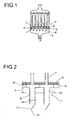
- FIG. 1 shows in the prior art apparatus 2 with a central cylindrical part, which is closed at both ends by a respective hemispherical hood 3.
- a feed opening 4 which in the FIG. 1 illustrated embodiment, for example, centrally located in the lower hood 3, a gas-liquid phase mixture is introduced into the apparatus 2 in the lower hood 3 and distributed uniformly via a distributor device 1.
- the distributor device 1 comprises a horizontal bottom 5 and a multiplicity of liquid phase guide elements 6 extending in the direction of the feed opening 4, which can be designed, for example, as tubes.
- the apparatus 2 is designed as a tube bundle reactor, with a central cylindrical part, are arranged in the tubes 7 in the tube tubes 8. Below the lower tube plate 8 a holder 9 is arranged.
- the distributor device 1 is arranged in the apparatus 2 such that there is a spacing between the horizontal bottom 5 and the lower tube plate 8, in particular if a liquid phase guide element 6 is assigned to a plurality of contact tubes 7.
- FIG. 2 shows a detail of the distribution device of FIG. 1
- the distributor device 1 comprises a horizontal bottom 5, in which downwardly extending liquid phase guide elements 6 are inserted or welded.
- openings 10 are arranged on each liquid phase guide element 6 superimposed. Through these openings 10 preferably dispersed the gas phase, which has dammed up to a gas cushion below the horizontal bottom 5.
- each liquid phase guide member 6 includes an opening 11 at a lower end 12 through which the liquid phase flows.
- the gas phase flows through one or more openings 10 of the liquid phase guide element 6, whereby the liquid phase can pass both through the opening 11 and also through one or more openings 10.
- each liquid phase guide element 6 may preferably be closed, so that the rising gas phase does not enter directly into the interior of the liquid phase guide element 6.
- a beveled cap is provided, which allows falling catalyst particles can escape from the liquid phase guide element 6 without clogging openings 10,11.
- the horizontal floor 5 is fixed by means of spacers 13 to the tube sheet 8, whereby also the holder 9 can be fixed.
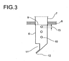
- FIG. 3 a distributor device 1 used according to the invention is shown, wherein the tube plate 8, in which the contact tubes 7 of an apparatus designed as a tube bundle reactor 2 are welded, plugged or screwed, acts as a horizontal bottom 5, at which the ascending gas phase is dammed to a gas cushion.
- Each contact tube 7, a designed as a tube liquid phase guide element 6 is associated, which can be inserted or welded into the contact tube 7.
- a sudhalterost 9 is arranged, on which lie the catalyst particles, with which the contact tubes 7 are filled.
- openings 10 are provided through which the gas phase is dispersed.
- the diameters 15 of the openings 10 lying one below the other may preferably be different, wherein they decrease, for example, with the distance to the tube sheet 8.
- an opening 11 for the liquid phase is provided at the lower end 12 of each liquid phase guide element 6, whereby falling catalyst particles are discharged to the outside and not clog openings 10, 11.
Abstract
Description
Die Erfindung betrifft einen Rohrbündelreaktor mit einer Verteilervorrichtung für ein Gas-Flüssigphasengemisch zur gleichmäßigen Verteilung einer Gas- und einer Flüssigphase über den Querschnitt des Rohrbündelreaktors.The invention relates to a tube bundle reactor with a distributor device for a gas-liquid phase mixture for the uniform distribution of a gas and a liquid phase over the cross section of the tube bundle reactor.
Bei chemischen Prozessen ist es häufig erforderlich, eine Gas- und eine Flüssigphase, insbesondere in Form eines Gas-Flüssigphasengemisches, in einen Apparat über mindestens eine Zuführöffnung einzuleiten, deren hydraulischer Durchmesser im Vergleich zum hydraulischen Durchmesser des Apparates kleiner sein kann. Bedingt durch die hydraulischen Durchmesserverhältnisse und die damit einhergehenden Strömungsverhältnisse sowie dem herrschenden Dichteunterschied zwischen Gas- und Flüssigphase kommt es insbesondere zu einer ungleichmäßigen Verteilung der Gasphase über den Querschnitt des Apparates. Dies führt zu Problemen, vor allem wenn im Apparat ein kontinuierliches Festbett angeordnet ist, oder aber mit Feststoffpartikeln, beispielsweise Katalysatoren, gefüllte Kontaktrohre oder Spalten zwischen Thermoblechplatten vorhanden sind. Aber auch schon in der Zuführung kann es durch entsprechende Strömungsverhältnisse zu einer gewissen Trennung von Gas- und Flüssigphase oder auch zu einer ungleichförmigen Einleitung von Gas- und Flüssigphase kommen, die eine Vergleichmäßigung des Einleitungsstromes notwendig machen.In chemical processes, it is often necessary to introduce a gas phase and a liquid phase, in particular in the form of a gas-liquid phase mixture, into an apparatus via at least one feed opening whose hydraulic diameter can be smaller compared to the hydraulic diameter of the apparatus. Due to the hydraulic diameter ratios and the concomitant flow conditions and the prevailing density difference between gas and liquid phase, there is in particular an uneven distribution of the gas phase over the cross section of the apparatus. This leads to problems, especially if in the apparatus a continuous fixed bed is arranged, or with solid particles, such as catalysts, filled catalyst tubes or gaps between thermoplates are present. But even in the feed, it can come by appropriate flow conditions to a certain separation of the gas and liquid phase or to a non-uniform introduction of gas and liquid phase, which make it necessary to make the Einleitungsstromes equalization.
Darüber hinaus erweist sich das Zuführen eines zweiphasigen Gemisches und eine gleichmäßige Verteilung desselben über den Querschnitt des Apparates als problematisch, da durch eine Veränderung in der Gas-Flüssigverteilung oder in der Komponentenzusammensetzung in den zwei Phasen ein zusätzlicher Freiheitsgrad in dem zweiphasigen Gemisch vorliegt. So kann eine ungleichmäßige Verteilung der Phasen zu einer Verschiebung des Gleichgewichtes und somit zu einer lokalen Veränderung der Komponentenzusammensetzung der einzelnen Phasen führen. Beispielsweise kann es in den Randgebieten, die von der Gasphase nur unzureichend erreicht werden, zum Verdampfen einer Komponente aus der Flüssigphase kommen, so dass diese an dieser Komponente verarmt.Moreover, feeding a biphasic mixture and evenly distributing it across the cross-section of the apparatus proves problematic because there is an additional degree of freedom in the biphasic mixture due to a change in the gas-liquid distribution or in the component composition in the two phases. Thus, an uneven distribution of the phases can lead to a shift in the equilibrium and thus to a local change in the component composition of the individual phases. For example, in the peripheral regions, which are insufficiently achieved by the gas phase, evaporation of a component from the liquid phase may occur, so that it becomes depleted of this component.
Apparate für chemische Reaktionen, in denen ein Gas-Flüssigphasengemisch eingeleitet wird, weisen unter anderem einen zentralen, zylinderförmigen oder prismatischen Teil auf, in dem die chemische Reaktion stattfindet. Gegebenenfalls wird die chemische Reaktion katalysiert, wobei in dem Apparat ein kontinuierliches Festbett, mit Katalysatoren oder Katalysatorpartikeln gefüllte Kontaktrohre oder Thermoblechplatten mit dazwischen angeordneten Spalten vorgesehen ist. An beiden Enden ist der Apparat durch Deckel oder Böden geschlossen, die beispielsweise flach oder gewölbt, in Form von Klöpperböden, Korbbogenböden oder Kugelschalen ausgebildet sind.Apparatuses for chemical reactions in which a gas-liquid phase mixture is introduced have inter alia a central, cylindrical or prismatic part in which the chemical reaction takes place. If necessary, the chemical Catalyses reaction, wherein in the apparatus is provided a continuous fixed bed, filled with catalysts or catalyst particles catalyst tubes or thermoplates with columns arranged therebetween. At both ends of the apparatus is closed by lids or bottoms, which are formed, for example, flat or curved, in the form of dished ends, basket sheet floors or spherical shells.
Im Bereich eines unteren Bodens werden eine Gas- und eine Flüssigphase über mindestens eine Zuführöffnung einer Zuführeinrichtung in den Apparat eingeleitet. Beim Eintreten eines Gas-Flüssigphasengemisches durch die Zuführöffnung in den Innenraum des Apparates kann es dort durch Koaleszenz der Gasphase zur Ausbildung großer Gasblasen oder eines Gasstrahls kommen, die zentral aufsteigen und gegebenenfalls auf die Oberfläche eines Festbettes beziehungsweise eines Rohrbodens prallen, in dem die Kontaktrohre angeordnet sind. Im Gegensatz dazu werden die äußeren Bereiche des Apparats von der Gasphase nur unzureichend erreicht, wodurch es dort zu einer ungleichmäßigen Verteilung kommt. Unter Umständen findet zusätzlich ein Phasenübergang einer oder mehrerer Komponenten statt, und damit ergibt sich ein lokal verändertes Gleichgewicht. Dies bedingt in dem Apparat eine Uneinheitlichkeit in den Reaktionsbedingungen, wodurch die chemische Reaktion nicht optimal verläuft. Aber auch schon in der Zuführung kann es zu einer ungleichmäßigen Verteilung der beiden Phasen kommen. Darüber hinaus führen unterschiedlich große Gasblasen zu einer unerwünschten ungleichmäßigen Verteilung der beiden Phasen über den Apparatequerschnitt.In the region of a lower bottom, a gas phase and a liquid phase are introduced into the apparatus via at least one feed opening of a feed device. Upon entry of a gas-liquid phase mixture through the feed opening into the interior of the apparatus, coalescence of the gas phase may result in the formation of large gas bubbles or a gas jet which rise centrally and possibly impinge on the surface of a fixed bed or a tube bottom in which the contact tubes are arranged are. In contrast, the outer areas of the apparatus are insufficiently reached by the gas phase, resulting in an uneven distribution there. Under certain circumstances, in addition, a phase transition of one or more components takes place, and thus results in a locally altered equilibrium. This causes an inconsistency in the reaction conditions in the apparatus, whereby the chemical reaction is not optimal. But even in the feeder, there may be an uneven distribution of the two phases. In addition, different sized gas bubbles lead to an undesirable non-uniform distribution of the two phases over the apparatus cross-section.
Um eine Vergleichmäßigung der Verteilung des Gas-Flüssigphasengemisches zu erzielen und um die beschriebenen Probleme zu vermeiden, ist es notwendig, Verteilervorrichtungen im Bereich der Zuführöffnung einzusetzen.In order to achieve a homogenization of the distribution of the gas-liquid phase mixture and to avoid the problems described, it is necessary to use distribution devices in the region of the feed opening.
Aus
Im Gegensatz dazu steht ein sich über den gesamten Querschnitt des Apparates erstreckender Siebboden, an dem sowohl die Gasphase als auch die Flüssigphase durch gleiche Öffnungen des Siebbodens gleichmäßig über den Apparatequerschnitt dispergieren. Ein derartiger Siebboden erzeugt einen hohen Druckverlust in dem Apparat, wodurch die Betriebskosten sich erhöhen. Allerdings hat sich gezeigt, dass ein Siebboden ungeeignet ist, um ein mehrphasiges Gemisch zu vergleichmäßigen. Ein Einsatz in Apparaten mit einem Festbett, erschwert den Zugriff auf das dahinter liegende Festbett, der insbesondere notwendig sein kann, um im Falle eines Katalysatorfestbettes den verbrauchten Katalysator auszutauschen.In contrast, there is a sieve bottom extending over the entire cross section of the apparatus, at which both the gas phase and the liquid phase uniformly disperse through the same openings of the sieve bottom over the apparatus cross section. Such a sieve tray creates a high pressure loss in the apparatus, thereby increasing operating costs. However, it has been found that a sieve bottom is unsuitable for uniforming a multiphase mixture. A use in apparatus with a fixed bed, difficult access to the underlying fixed bed, which may be necessary in particular in the case of a fixed catalyst bed to replace the spent catalyst.
Ringverteiler, die in einem Rohrboden untergebracht sind und eine Vielzahl von Öffnungen zur Vergleichmäßigung einer Verteilung aufweisen, benötigen ein großes Einbauvolumen, da für eine gleichmäßige Verteilung mehrere Ringe mit einer großen Anzahl von Öffnungen notwendig sind. Als problematisch erweist sich, dass innerhalb des Ringverteilers eine einheitliche Strömung des Zweiphasengemisches gewährleistet sein muss, um keine Verschiebung der Gas- Flüssigverteilung über den Strömungsquerschnitt zu erzeugen.Ring manifolds, which are housed in a tubesheet and have a plurality of openings to equalize a distribution, require a large installation volume, since a uniform distribution several rings with a large number of openings are necessary. A problem proves to be that within the ring manifold a uniform flow of the two-phase mixture must be ensured in order to produce any shift of the gas-liquid distribution over the flow cross-section.
Aus
Dem gegenüber ist es Aufgabe der vorliegenden Erfindung, einen Rohrbündelreaktor mit einer Verteilervorrichtung für eine Gas- und eine Flüssigphase zur Verfügung zu stellen, um eine über den gesamten Querschnitt des Rohrbündelreaktors gleichmäßige Verteilung zu erreichen, welche unabhängig von deren Separations- und Koaleszenzverhalten sowie dem herrschenden Strömungsverhältnissen ist. Insbesondere soll eine gleichförmige Verteilung über den gesamten Querschnitt des Rohrbündelreaktors bei einer konstanten Zusammensetzung der Phasen gewährleistet sein, wobei die Verteilervorrichtung konstruktiv einfach und entsprechend kostengünstig sein soll.On the other hand, it is an object of the present invention to provide a tube bundle reactor with a distributor device for a gas and a liquid phase in order to achieve a uniform over the entire cross section of the tube bundle reactor distribution, which regardless of their Separations- and Koaleszenzverhalten and the prevailing Flow conditions is. In particular, a uniform distribution should be ensured over the entire cross section of the tube bundle reactor with a constant composition of the phases, wherein the distributor device should be structurally simple and correspondingly inexpensive.
Die Aufgabe wird durch einen Rohrbündelreaktor mit Kontaktrohren und einer Verteilervorrichtung für ein Gas- Flüssigphasengemisch gelöst, wobei eine Gas- und eine Flüssigphase über mindestens eine Zuführöffnung in der unteren Haube des Rohrbündelreaktors geleitet wird, dadurch gekennzeichnet, dass die Verteilervorrichtung einen horizontalen Boden umfasst, der einem Rohrboden des Rohrbündelreaktors entspricht, an welchem sich die aufsteigende Gasphase zu einem Gaspolster aufstaut, und an dem Boden angeordnete vertikale, stromaufwärts offene Flüssigphasenführungselemente umfasst, die sich in Richtung der Zuführöffnung durch das sich ausbildende Gaspolster hinaus in die Flüssigphase erstrecken, wobei am Umfang der Flüssigphasenführungselemente mindestens eine Öffnung für die Gasphase im Bereich des sich ausbildenden Gaspolsters vorgesehen ist. Die vertikalen Flüssigphasenführungselemente sind als Verlängerung der Kontaktrohre ausgebildet.The object is achieved by a tube bundle reactor with contact tubes and a distributor device for a gas-liquid phase mixture, wherein a gas and a liquid phase is passed through at least one feed opening in the lower hood of the tube bundle reactor, characterized in that the distributor device comprises a horizontal bottom, the corresponds to a tube plate of the tube bundle reactor, at which the ascending gas phase dammed up to a gas cushion, and at bottom vertical upstream, upstream liquid phase guide elements, which extend in the direction of the feed opening through the gas cushion forming into the liquid phase, wherein at the periphery of the liquid phase guide elements at least one opening for the gas phase in the region of the forming gas cushion is provided. The vertical liquid phase guide elements are formed as an extension of the contact tubes.
Die Verteilervorrichtung findet Verwendung in einem Rohrbündelapparat, in dem eine Vielzahl von Kontaktrohren in Rohrböden eingeschweißt sind, wobei das Gas-Flüssigphasengemisch über eine Zuführöffnung in einer Haube zugeführt, beispielsweise durch die Kontaktrohre geleitet und über die andere Haube aus dem Apparat abgezogen wird.The distributor device is used in a tube bundle apparatus, in which a plurality of contact tubes are welded into tubesheets, wherein the gas-liquid phase mixture is supplied via a feed opening in a hood, for example, passed through the contact tubes and withdrawn from the apparatus via the other hood.
Die bisher auftretende ungleichförmige Verteilung einer Gas- und Flüssigphase entsteht unter anderem dadurch, dass der hydraulische Durchmesser der Zuführöffnung um ein Vielfaches kleiner ist als der hydraulische Durchmesser des Apparates. Als "hydraulischer Durchmesser" wird in der Strömungstechnik das Verhältnis aus dem Vierfachen der Fläche zu dem Umfang einer Öffnung bezeichnet. Aufgrund des Dichteunterschieds zwischen Gasphase und Flüssigphase steigen die Gasblasen eines Zweiphasengemisches schneller auf, beziehungsweise durch Koaleszenzverhalten und/oder Strömungsverhältnissen an der Zuführöffnung bzw. in der Zuführung kann es zur Ausbildung von großen Gasblasen oder eines Gasstrahles kommen, so dass die Gasphase mit hoher Geschwindigkeit weitgehend zentral aufsteigt.The previously occurring non-uniform distribution of a gas and liquid phase arises inter alia by the fact that the hydraulic diameter of the feed opening is many times smaller than the hydraulic diameter of the apparatus. The term "hydraulic diameter" in the flow technique refers to the ratio of four times the area to the circumference of an opening. Due to the density difference between the gas phase and the liquid phase, the gas bubbles of a two-phase mixture increase faster, or by coalescing and / or flow conditions at the feed or in the supply can lead to the formation of large gas bubbles or a gas jet, so that the gas phase at high speed largely ascends centrally.
Eine erfindungsgemäß eingesetzte Verteilervorrichtung nutzt die durch die Dichte- und Strömungsverhältnisse hervorgerufene Separierung der Gas- und der Flüssigphase an der Verteilervorrichtung. Die Verteilervorrichtung umfasst einen horizontalen Boden, der beispielsweise als eine sich über den gesamten Querschnitt des Apparates erstreckende Platte ausgebildet sein kann. An diesem horizontalen Boden staut sich die Gasphase zu einem Gaspolster auf. An dem horizontalen Boden sind vertikale Flüssigphasenführungselemente angeordnet, beispielsweise gestaltet als sich nach unten in Richtung Zuführöffnung erstreckende Rohre, welche stromaufwärts eine Öffnung aufweisen. Die Länge der Rohre ist derart gewählt, dass sie die Höhe des sich ausbildenden Gaspolsters übersteigt und somit durch das aufgestaute Gaspolster in die Flüssigkeit reichen.A distributor device used according to the invention uses the separation of the gas phase and the liquid phase at the distributor device caused by the density and flow conditions. The distributor device comprises a horizontal bottom, which may be formed, for example, as a plate extending over the entire cross-section of the apparatus. At this horizontal floor, the gas phase accumulates to a gas cushion. Vertical liquid phase guide elements are arranged on the horizontal base, for example designed as tubes which extend downwards in the direction of the feed opening and which have an opening upstream. The length of the tubes is chosen so that it exceeds the height of the forming gas cushion and thus reach through the pent-up gas cushion in the liquid.
Jedes vertikale Flüssigphasenführungselement weist an seinem unteren Bereich vorzugsweise eine periphere Öffnung auf, durch welche die Flüssigphase strömen kann. Das untere Ende jedes vertikalen Flüssigphasenführungselementes kann vorzugsweise derart ausgebildet sein, dass die von der Zuführöffnung des Apparates in Form von Gasblasen oder Gasstrahlen aufsteigende Gasphase nicht direkt in das Innere strömen kann.Each vertical liquid phase guide member preferably has at its lower portion a peripheral opening through which the liquid phase can flow. The lower end of each vertical liquid phase guide element may preferably be formed such that the from the feed opening of the apparatus in the form of Gas bubbles or gas jets ascending gas phase can not flow directly into the interior.
Die sich zu einem Gaspolster aufstauende Gasphase gelangt vorzugsweise über mindestens eine Öffnung am Umfang der einzelnen vertikalen Flüssigphasenführungselemente in Höhe des sich ausbildenden Gaspolsters in den im Innenraum vorliegenden Flüssigphasenstrom. Dadurch steht der Flüssigphase und der Gasphase im Innenraum der Flüssigphasenführungselemente ein gemeinsamer Strömungsweg zur Verfügung. Nach der anfänglichen Separierung von Gas- und Flüssigphase werden dadurch die beiden Phasen derart miteinander in Kontakt gebracht, dass sich eine gleichmäßige Verteilung einstellen kann. Eine Vielzahl entsprechender vertikaler Flüssigphasenführungselemente, gleichmäßig über den Querschnitt des Apparates verteilt, und welche Öffnungen stromaufwärts für die Zweiphasenströmung zur Verfügung stellen, gewährleistet eine Vergleichmäßigung der Verteilung des Gas-Flüssigphasengemisches über den Querschnitt des Apparates.The gas phase which accumulates to form a gas cushion preferably passes through at least one opening on the circumference of the individual vertical liquid phase guide elements in the amount of the gas cushion forming in the liquid phase stream present in the interior. As a result, a common flow path is available to the liquid phase and the gas phase in the interior of the liquid phase guide elements. After the initial separation of the gas and liquid phases, the two phases are thereby brought into contact with each other in such a way that a uniform distribution can occur. A plurality of respective vertical liquid phase guide elements, evenly distributed across the cross-section of the apparatus and which provide upstream openings for the two-phase flow, ensure equalization of the distribution of the gas-liquid phase mixture across the cross-section of the apparatus.
Die erfindungsgemäß eingesetzte Verteilervorrichtung umfasst einen horizontalen Boden, in welchen eine Vielzahl von Rohren eingesteckt oder eingeschweißt ist. Die Rohre erstrecken sich nach unten in Richtung der Zuführöffnung und weisen ein unteres verschlossenes Ende auf, wodurch eine direkte Anströmung der Gasphase nicht möglich ist. Eine Abdeckung des unteren Endes kann beispielsweise als Kappe, Glocke oder ähnliches ausgebildet sein. Rohre, welche in einem Randbereich des Apparates angeordnet sind und damit weitestgehend nicht im Anströmbereich der aufsteigenden Gasblasen liegen, können ohne Abdeckung ausgebildet sein, wodurch eine Platzersparnis erreicht wird. Die Abdeckung kann schräg ausgeführt sein, so dass herabfallende Katalysatorpartikel einer oberhalb angeordneten Katalysatorschüttung aus dem Rohr abgeführt werden können, ohne eine Verstopfung einer Öffnung hervorzurufen.The distributor device used according to the invention comprises a horizontal base in which a plurality of tubes is inserted or welded. The tubes extend downwards in the direction of the feed opening and have a lower closed end, whereby a direct flow of the gas phase is not possible. A cover of the lower end may be formed, for example, as a cap, bell or the like. Tubes, which are arranged in an edge region of the apparatus and thus largely do not lie in the inflow region of the rising gas bubbles, can be formed without cover, whereby a space saving is achieved. The cover can be made oblique, so that falling catalyst particles of a catalyst bed arranged above can be removed from the tube without causing a blockage of an opening.
Die Höhe des sich ausbildenden Gaspolsters stellt sich in Abhängigkeit von dem herrschenden Druckverlust der Gasströmung durch die Verteilerplatte, dem Druckverlust der Flüssigphase und dem hydrostatischen Druckunterschied von Gas und Flüssigkeit ein. Je nach Dichteunterschied zwischen Gas- und Flüssigphase, Gasvolumenstrom bzw. Lastfall stellt sich demnach eine Höhe des Gaspolsters ein, die sich stark unterscheiden kann. Vorzugsweise sind die Rohre mit mehreren vertikal untereinander liegenden Öffnungen für die Gasphase versehen, durch welche je nach Höhe des Gaspolsters die Gasphase bzw. die Flüssigphase durchströmen.The height of the forming gas cushion is a function of the prevailing pressure loss of the gas flow through the distributor plate, the pressure loss of the liquid phase and the hydrostatic pressure difference of gas and liquid. Depending on the density difference between gas and liquid phase, gas flow or load case, accordingly, a height of the gas cushion, which can vary greatly. Preferably, the tubes are provided with a plurality of vertically underlying openings for the gas phase, through which, depending on the height of the gas cushion, the gas phase or the liquid phase flow through.
Die für die Gasphase bereitgestellten vertikal untereinander liegenden Öffnungen können insbesondere unterschiedliche Durchmesser aufweisen. Sie liegen bevorzugt in einem Bereich von 1 mm bis 10 mm.The provided for the gas phase vertically underlying openings may in particular have different diameters. They are preferably in a range of 1 mm to 10 mm.
Die Rohre, die den gemeinsamen Strömungsweg von Flüssig- und Gasphase bereitstellen, können unterschiedliche Durchmesser haben.The tubes that provide the common flow path of liquid and gas phase may have different diameters.
Die erfindungsgemäß eingesetzte Verteilervorrichtung wird in einem als Rohrbündelreaktor ausgebildeten Apparat eingesetzt. In einem solchen Apparat sind Kontaktrohre in mindestens einem Rohrboden eingeschweißt und enthalten eine Katalysatorschüttung. Um eine gleichmäßige Beaufschlagung der einzelnen Kontaktrohre mittels der erfindungsgemäßen Verteilervorrichtung mit dem Gas-Flüssigphasengemisch zu erzielen, ist je ein als Rohr ausgebildetes Flüssigphasenführungselement der Verteilervorrichtung mindestens einem Kontaktrohr zugeordnet.The distributor device used according to the invention is used in an apparatus designed as a tube bundle reactor. In such an apparatus, catalyst tubes are welded into at least one tubesheet and contain a catalyst bed. In order to achieve a uniform admission of the individual contact tubes by means of the distributor device according to the invention with the gas-liquid phase mixture, a respective liquid-phase guide element designed as a tube is assigned to the distributor device at least one contact tube.
Damit die Höhe des sich ausbildenden Gaspolsters über den Querschnitt des Apparates möglichst konstant ist, wird der horizontale Boden der Verteilervorrichtung in dem Apparat nach Möglichkeit horizontal ausgerichtet.So that the height of the forming gas cushion over the cross section of the apparatus is as constant as possible, the horizontal bottom of the distributor device in the apparatus is aligned horizontally if possible.
Die erfindungsgemäß eingesetzte Verteilervorrichtung nutzt den unteren Rohrboden des als Rohrbündelreaktor ausgebildeten Apparates als horizontalen Boden der Verteilervorrichtung, an dem die Separierung von Gas- und Flüssigphase erfolgt. Die vertikalen Flüssigphasenführungselemente der Verteilervorrichtung, die entsprechend mit Öffnungen für die Flüssigphase und die Gasphase versehen sind, werden bevorzugt als Einsteckrohre der in dem Rohrboden eingeschweißten Kontaktrohre ausgebildet und stellen damit eine Verlängerung derselben dar. Jedes Einsteckrohr kann ein Rückhaltesieb enthalten, welches die Katalysatorpartikel trägt.The distributor device used according to the invention uses the lower tube plate of the device designed as a tube bundle reactor as the horizontal bottom of the distributor device, at which the separation of gas and liquid phase takes place. The vertical liquid phase guide elements of the distributor device, which are respectively provided with openings for the liquid phase and the gas phase, are preferably formed as plug-in tubes of the welded in the tube sheet catalyst tubes and thus represent an extension of the same. Each plug-in tube may contain a retaining screen, which carries the catalyst particles.
Durch umfangreiche Untersuchungen konnte gefunden werden, dass sich das Problem einer Ungleichmäßigkeit in der Verteilung eines Gas-Flüssigphasengemisches über den Querschnitt eines Apparates in einfacher Weise durch die oben definierte Verteilervorrichtung lösen lässt, wodurch Ungleichmäßigkeiten über den Querschnitt des Apparates sowohl bezüglich der Gasphase als auch bezüglich der Zusammensetzung der Phasen vermieden werden.Extensive research has found that the problem of unevenness in the distribution of a gas-liquid phase mixture across the cross-section of an apparatus can be easily solved by the above-defined distributor device, whereby unevenness in the cross-section of the apparatus both with respect to the gas phase and with respect the composition of the phases are avoided.
Die Erfindung wird im Folgenden anhand der Zeichnung näher erläutert.The invention will be explained in more detail below with reference to the drawing.
Es zeigt im Einzelnen:
Figur 1- einen Längsschnitt durch einen als Rohrbündelreaktor ausgebildeten Apparat mit einer Verteilervorrichtung in der unteren Haube gemäß dem Stand der Technik;
Figur 2- ein Detail der
Verteilervorrichtung von Figur 1 ; Figur 3- einen Längsschnitt einer erfindungsgemäß eingesetzten Verteilervorrichtung.
- FIG. 1
- a longitudinal section through an apparatus designed as a tube bundle reactor apparatus with a distributor device in the lower hood according to the prior art;
- FIG. 2
- a detail of the distribution device of
FIG. 1 ; - FIG. 3
- a longitudinal section of a distributor device used in the invention.
Die Längsschnittdarstellung in
In der
Das untere Ende 12 jedes Flüssigphasenführungselementes 6 kann bevorzugt verschlossen sein, so dass die aufsteigende Gasphase nicht unmittelbar in den Innenraum des Flüssigphasenführungselementes 6 eintritt. Hierfür ist eine abgeschrägte Kappe vorgesehen, die es ermöglicht, dass herabfallende Katalysatorpartikel aus dem Flüssigphasenführungselement 6 austreten können ohne Öffnungen 10,11 zu verstopfen.The
Der horizontale Boden 5 wird mittels von Abstandshaltern 13 an dem Rohrboden 8 befestigt, wodurch ebenfalls das Halterost 9 fixiert werden kann.The
In
Claims (6)
- A shell-and-tube reactor (2) having contact tubes (7) which are welded into tube plates (8) and are located in a cylindrical part of the shell-and-tube reactor (2) which is closed off at its lower and its upper end respectively by an end cap (3), with a gas phase and a liquid phase being fed in via at least one feed opening (4) in the lower end cap (3) and being discharged from the reactor via the upper end cap (3), wherein said reactor has a distributor device (1) having a horizontal plate (5) at which the ascending gas phase backs up to form a gas cushion and vertical elements (6) which conduct the liquid phase and are arranged on the horizontal plate (5) and are open in the upstream direction and project outward in the direction of the feed opening through the gas cushion formed, with at least one opening (10) for the gas phase being provided on the circumference of the elements (6) which conduct the liquid phase in the region of the gas cushion formed and at least one opening (11) for the liquid phase, and the distributor device (1) being further configured so that the horizontal plate (5) is the tube plate (8) of the apparatus (2) and the vertical elements (6) which conduct the liquid phase are formed as extensions of the contact tubes (7).
- The shell-and-tube reactor (2) according to claim 1, wherein a plurality of openings (10) are arranged vertically underneath one another in a row or vertical slits are provided for the gas phase on the circumference of the vertical elements (6) which conduct the liquid phase.
- The shell-and-tube reactor (2) according to claim 2, wherein the plurality of openings (10) for the gas phase arranged vertically underneath one another in a row have different sizes (15).
- The shell-and-tube reactor (2) according to any of claims 1 to 3, wherein a plurality of rows of openings (10) for the gas phase arranged vertically underneath one another are provided on the circumference of the vertical elements (6) which conduct the liquid phase.
- The shell-and-tube reactor (2) according to any of claims 1 to 4, wherein the vertical elements (6) which conduct the liquid phase have different diameters.
- The shell-and-tube reactor (2) according to any of claims 1 to 5, wherein the vertical elements (6) which conduct the liquid phase are closed at their bottom end (12) by caps, which are slanted, hoods, bubble caps or other shapes.
Applications Claiming Priority (2)
| Application Number | Priority Date | Filing Date | Title |
|---|---|---|---|
| DE102005050283A DE102005050283A1 (en) | 2005-10-20 | 2005-10-20 | Distributor device for a gas-liquid phase mixture for apparatus |
| PCT/EP2006/067531 WO2007045666A1 (en) | 2005-10-20 | 2006-10-18 | Distribution device for a gas-liquid phase mixture for apparatus |
Publications (2)
| Publication Number | Publication Date |
|---|---|
| EP1940542A1 EP1940542A1 (en) | 2008-07-09 |
| EP1940542B1 true EP1940542B1 (en) | 2010-01-06 |
Family
ID=37564151
Family Applications (1)
| Application Number | Title | Priority Date | Filing Date |
|---|---|---|---|
| EP06807368A Not-in-force EP1940542B1 (en) | 2005-10-20 | 2006-10-18 | Tube bundle reactor with a distribution device for a gas-liquid phase mixture |
Country Status (7)
| Country | Link |
|---|---|
| US (1) | US7807116B2 (en) |
| EP (1) | EP1940542B1 (en) |
| JP (1) | JP5167138B2 (en) |
| CN (1) | CN101291725B (en) |
| AT (1) | ATE454210T1 (en) |
| DE (2) | DE102005050283A1 (en) |
| WO (1) | WO2007045666A1 (en) |
Families Citing this family (8)
| Publication number | Priority date | Publication date | Assignee | Title |
|---|---|---|---|---|
| US8517353B2 (en) * | 2010-09-27 | 2013-08-27 | Uop Llc | Apparatus and process for distributing vapor and liquid phases |
| CN102989317A (en) * | 2012-12-12 | 2013-03-27 | 北京坎普尔环保技术有限公司 | Internal pressure tubular membrane filter device with uniform aeration |
| US8987518B2 (en) | 2013-02-28 | 2015-03-24 | Basf Se | Polyamines and process for preparation thereof |
| EP2961787A1 (en) | 2013-02-28 | 2016-01-06 | Basf Se | Polyamines and method for the production thereof |
| CN105771773A (en) * | 2014-12-25 | 2016-07-20 | 佛山市宝航机械装备行业知识产权服务有限公司 | Pug stirring device |
| DE102015219305A1 (en) | 2015-10-06 | 2017-04-06 | Hydrogenious Technologies Gmbh | Reactor device for dehydrating a carrier medium |
| ES2769921T3 (en) * | 2015-11-26 | 2020-06-29 | Thyssenkrupp Ind Solutions Ag | Procedure for the epoxidation of an olefin |
| CN105363388B (en) * | 2015-12-02 | 2018-01-26 | 中国天辰工程有限公司 | A kind of multi-phase fluid distributed architecture for shell and tube reactor |
Family Cites Families (19)
| Publication number | Priority date | Publication date | Assignee | Title |
|---|---|---|---|---|
| US3197286A (en) * | 1963-02-18 | 1965-07-27 | Hydrocarbon Research Inc | Liquid phase reactor |
| US3524731A (en) * | 1968-09-30 | 1970-08-18 | Exxon Research Engineering Co | Mixed-phase flow distributor for packed beds |
| JPS5028208Y1 (en) * | 1973-09-14 | 1975-08-20 | ||
| NL8102307A (en) * | 1981-05-12 | 1982-12-01 | Esmil Bv | Apparatus and method for thickening by evaporation of a liquid. |
| US4764347A (en) * | 1983-04-05 | 1988-08-16 | Milligan John D | Grid plate assembly for ebullated bed reactor |
| ZA847002B (en) * | 1983-10-14 | 1985-05-29 | Hri Inc | Staged flow distribution grid assembly and method for ebullated bed reactor |
| US4707340A (en) * | 1983-10-14 | 1987-11-17 | Milligan John D | Staged guide plate and vessel assembly |
| JPS61287438A (en) * | 1985-06-14 | 1986-12-17 | Mitsubishi Heavy Ind Ltd | Dispersing device for three phase fluidized bed reactor |
| CA2141886E (en) * | 1994-05-11 | 1999-10-12 | Federico Zardi | Reactor for two-phase reactions, in particular for urea synthesis at high pressure and temperature |
| US5545382A (en) * | 1994-11-25 | 1996-08-13 | Uop | Process and apparatus for discharging particles and fluids from flow channels |
| US5683629A (en) * | 1995-06-02 | 1997-11-04 | Shell Oil Company | Horizontal tray and column for contacting gas and liquid |
| FR2745202B1 (en) * | 1996-02-27 | 1998-04-30 | Inst Francais Du Petrole | TRAY FOR DISTRIBUTING A POLYPHASIC MIXTURE THROUGH A CATALYTIC BED |
| KR100298855B1 (en) * | 1996-08-07 | 2001-11-14 | 다나카 쇼소 | Gas-liquid dispersion device and gas-liquid contact device and wastewater treatment device |
| US6029956A (en) | 1998-02-06 | 2000-02-29 | Foster Wheeler Usa Corporation | Predominantly liquid filled vapor-liquid chemical reactor |
| US6554994B1 (en) * | 1999-04-13 | 2003-04-29 | Chevron U.S.A. Inc. | Upflow reactor system with layered catalyst bed for hydrotreating heavy feedstocks |
| US20030223924A1 (en) | 2002-05-29 | 2003-12-04 | Bachtel Robert W. | Gas-pocket distributor and method of distributing gas |
| DE10329491A1 (en) * | 2003-07-01 | 2005-01-27 | Basf Ag | Reactor for gas / liquid or gas / liquid / solid reactions |
| EP1646444B1 (en) * | 2003-07-10 | 2013-09-11 | Institut Français du Pétrole | Valve plate for distributing a gaseous and liquid phases |
| DE10336260A1 (en) * | 2003-08-07 | 2004-05-19 | Basf Ag | Distributor promoting uniform gas flow in reactor containing fixed bed, includes perforated curved surface extended to vessel wall around gas supply opening |
-
2005
- 2005-10-20 DE DE102005050283A patent/DE102005050283A1/en not_active Withdrawn
-
2006
- 2006-10-18 DE DE502006005881T patent/DE502006005881D1/en active Active
- 2006-10-18 US US12/090,152 patent/US7807116B2/en not_active Expired - Fee Related
- 2006-10-18 CN CN2006800386797A patent/CN101291725B/en not_active Expired - Fee Related
- 2006-10-18 WO PCT/EP2006/067531 patent/WO2007045666A1/en active Application Filing
- 2006-10-18 AT AT06807368T patent/ATE454210T1/en active
- 2006-10-18 JP JP2008536050A patent/JP5167138B2/en not_active Expired - Fee Related
- 2006-10-18 EP EP06807368A patent/EP1940542B1/en not_active Not-in-force
Also Published As
| Publication number | Publication date |
|---|---|
| CN101291725A (en) | 2008-10-22 |
| EP1940542A1 (en) | 2008-07-09 |
| ATE454210T1 (en) | 2010-01-15 |
| US7807116B2 (en) | 2010-10-05 |
| DE502006005881D1 (en) | 2010-02-25 |
| DE102005050283A1 (en) | 2007-04-26 |
| CN101291725B (en) | 2010-06-23 |
| WO2007045666A1 (en) | 2007-04-26 |
| JP2009512547A (en) | 2009-03-26 |
| JP5167138B2 (en) | 2013-03-21 |
| US20080241021A1 (en) | 2008-10-02 |
Similar Documents
| Publication | Publication Date | Title |
|---|---|---|
| EP1940541B1 (en) | Distribution device for a gas-liquid phase mixture for apparatus | |
| EP1940542B1 (en) | Tube bundle reactor with a distribution device for a gas-liquid phase mixture | |
| DE60105445T2 (en) | MIXING DEVICE WITH SWIVEL CHAMBER FOR MIXING LIQUIDS | |
| DE60119211T2 (en) | Multipurpose partial assembly, which ensures Denkontakt, the distribution and the heat and / or material exchange in at least one gas phase and a liquid phase | |
| DE2943687C2 (en) | Trough-like device for collecting and distributing the liquid for a countercurrent column | |
| EP1663434B1 (en) | Bundled-tube reactor comprising a multi-phase fluid distributor | |
| EP3359288B1 (en) | Reactor device for dehydrating a carrier medium | |
| DE60221647T2 (en) | REACTOR | |
| DE1944420B2 (en) | CLOSED REACTOR FOR DISTRIBUTION OF DOWNWATER FLOWING LIQUIDS | |
| EP0231841B1 (en) | Apparatus for the uniform distribution of a liquid containing solid particles on a cross area | |
| DE112004002124B4 (en) | Rieselfil degasser with gratings | |
| DE1192625B (en) | Device for the simultaneous even distribution of a mixed phase of a gaseous and a liquid component over a fixed catalyst bed | |
| EP0552457B1 (en) | Distributor plate for mobile bed reactors | |
| EP1038562A1 (en) | Apparatus for collecting and distributing liquids in a column | |
| DE60125658T2 (en) | Device for injecting fluid between two layers for the simultaneous execution and distribution of a multiphase mixture | |
| EP0073415A2 (en) | Apparatus for dispensing a second phase into a first phase | |
| EP2233183B1 (en) | Liquid distributor | |
| DE3123695C2 (en) | ||
| EP0089486B1 (en) | Column of fluidised chambers | |
| DE1542499A1 (en) | Reactor for carrying out reactions in the gas phase using heterogeneous catalysis | |
| DE3434336A1 (en) | STEPPED POWER DISTRIBUTION GRID PLATE STRUCTURE AND METHOD FOR A FLUID BED REACTOR | |
| EP0232759B1 (en) | Pipe socket distributor for a disperse phase in a liquid-liquid extraction column, in a bubble column and a reaction column | |
| EP0132224A1 (en) | Bubble column reactor for gas-liquid exchange reactions | |
| DD227332B1 (en) | LIQUID DISTRIBUTION DEVICE FOR VERTICAL PIPE BOWL, ESPECIALLY FOR CASE FILM APPARATES | |
| DE3441999A1 (en) | Process and apparatus for circulating a liquid with the aid of gas |
Legal Events
| Date | Code | Title | Description |
|---|---|---|---|
| PUAI | Public reference made under article 153(3) epc to a published international application that has entered the european phase |
Free format text: ORIGINAL CODE: 0009012 |
|
| 17P | Request for examination filed |
Effective date: 20080520 |
|
| AK | Designated contracting states |
Kind code of ref document: A1 Designated state(s): AT BE BG CH CY CZ DE DK EE ES FI FR GB GR HU IE IS IT LI LT LU LV MC NL PL PT RO SE SI SK TR |
|
| 17Q | First examination report despatched |
Effective date: 20090112 |
|
| GRAP | Despatch of communication of intention to grant a patent |
Free format text: ORIGINAL CODE: EPIDOSNIGR1 |
|
| RTI1 | Title (correction) |
Free format text: TUBE BUNDLE REACTOR WITH A DISTRIBUTION DEVICE FOR A GAS-LIQUID PHASE MIXTURE |
|
| DAX | Request for extension of the european patent (deleted) | ||
| GRAS | Grant fee paid |
Free format text: ORIGINAL CODE: EPIDOSNIGR3 |
|
| GRAA | (expected) grant |
Free format text: ORIGINAL CODE: 0009210 |
|
| AK | Designated contracting states |
Kind code of ref document: B1 Designated state(s): AT BE BG CH CY CZ DE DK EE ES FI FR GB GR HU IE IS IT LI LT LU LV MC NL PL PT RO SE SI SK TR |
|
| REG | Reference to a national code |
Ref country code: GB Ref legal event code: FG4D Free format text: NOT ENGLISH |
|
| REG | Reference to a national code |
Ref country code: CH Ref legal event code: EP |
|
| REG | Reference to a national code |
Ref country code: IE Ref legal event code: FG4D |
|
| REF | Corresponds to: |
Ref document number: 502006005881 Country of ref document: DE Date of ref document: 20100225 Kind code of ref document: P |
|
| PG25 | Lapsed in a contracting state [announced via postgrant information from national office to epo] |
Ref country code: SI Free format text: LAPSE BECAUSE OF FAILURE TO SUBMIT A TRANSLATION OF THE DESCRIPTION OR TO PAY THE FEE WITHIN THE PRESCRIBED TIME-LIMIT Effective date: 20100106 |
|
| LTIE | Lt: invalidation of european patent or patent extension |
Effective date: 20100106 |
|
| PG25 | Lapsed in a contracting state [announced via postgrant information from national office to epo] |
Ref country code: IS Free format text: LAPSE BECAUSE OF FAILURE TO SUBMIT A TRANSLATION OF THE DESCRIPTION OR TO PAY THE FEE WITHIN THE PRESCRIBED TIME-LIMIT Effective date: 20100506 Ref country code: ES Free format text: LAPSE BECAUSE OF FAILURE TO SUBMIT A TRANSLATION OF THE DESCRIPTION OR TO PAY THE FEE WITHIN THE PRESCRIBED TIME-LIMIT Effective date: 20100417 Ref country code: LT Free format text: LAPSE BECAUSE OF FAILURE TO SUBMIT A TRANSLATION OF THE DESCRIPTION OR TO PAY THE FEE WITHIN THE PRESCRIBED TIME-LIMIT Effective date: 20100106 Ref country code: PT Free format text: LAPSE BECAUSE OF FAILURE TO SUBMIT A TRANSLATION OF THE DESCRIPTION OR TO PAY THE FEE WITHIN THE PRESCRIBED TIME-LIMIT Effective date: 20100506 |
|
| REG | Reference to a national code |
Ref country code: IE Ref legal event code: FD4D |
|
| PG25 | Lapsed in a contracting state [announced via postgrant information from national office to epo] |
Ref country code: FI Free format text: LAPSE BECAUSE OF FAILURE TO SUBMIT A TRANSLATION OF THE DESCRIPTION OR TO PAY THE FEE WITHIN THE PRESCRIBED TIME-LIMIT Effective date: 20100106 Ref country code: LV Free format text: LAPSE BECAUSE OF FAILURE TO SUBMIT A TRANSLATION OF THE DESCRIPTION OR TO PAY THE FEE WITHIN THE PRESCRIBED TIME-LIMIT Effective date: 20100106 Ref country code: PL Free format text: LAPSE BECAUSE OF FAILURE TO SUBMIT A TRANSLATION OF THE DESCRIPTION OR TO PAY THE FEE WITHIN THE PRESCRIBED TIME-LIMIT Effective date: 20100106 |
|
| PG25 | Lapsed in a contracting state [announced via postgrant information from national office to epo] |
Ref country code: CY Free format text: LAPSE BECAUSE OF FAILURE TO SUBMIT A TRANSLATION OF THE DESCRIPTION OR TO PAY THE FEE WITHIN THE PRESCRIBED TIME-LIMIT Effective date: 20100106 Ref country code: SE Free format text: LAPSE BECAUSE OF FAILURE TO SUBMIT A TRANSLATION OF THE DESCRIPTION OR TO PAY THE FEE WITHIN THE PRESCRIBED TIME-LIMIT Effective date: 20100106 Ref country code: EE Free format text: LAPSE BECAUSE OF FAILURE TO SUBMIT A TRANSLATION OF THE DESCRIPTION OR TO PAY THE FEE WITHIN THE PRESCRIBED TIME-LIMIT Effective date: 20100106 Ref country code: GR Free format text: LAPSE BECAUSE OF FAILURE TO SUBMIT A TRANSLATION OF THE DESCRIPTION OR TO PAY THE FEE WITHIN THE PRESCRIBED TIME-LIMIT Effective date: 20100407 Ref country code: IE Free format text: LAPSE BECAUSE OF FAILURE TO SUBMIT A TRANSLATION OF THE DESCRIPTION OR TO PAY THE FEE WITHIN THE PRESCRIBED TIME-LIMIT Effective date: 20100106 Ref country code: RO Free format text: LAPSE BECAUSE OF FAILURE TO SUBMIT A TRANSLATION OF THE DESCRIPTION OR TO PAY THE FEE WITHIN THE PRESCRIBED TIME-LIMIT Effective date: 20100106 |
|
| PLBE | No opposition filed within time limit |
Free format text: ORIGINAL CODE: 0009261 |
|
| STAA | Information on the status of an ep patent application or granted ep patent |
Free format text: STATUS: NO OPPOSITION FILED WITHIN TIME LIMIT |
|
| PG25 | Lapsed in a contracting state [announced via postgrant information from national office to epo] |
Ref country code: BG Free format text: LAPSE BECAUSE OF FAILURE TO SUBMIT A TRANSLATION OF THE DESCRIPTION OR TO PAY THE FEE WITHIN THE PRESCRIBED TIME-LIMIT Effective date: 20100406 Ref country code: SK Free format text: LAPSE BECAUSE OF FAILURE TO SUBMIT A TRANSLATION OF THE DESCRIPTION OR TO PAY THE FEE WITHIN THE PRESCRIBED TIME-LIMIT Effective date: 20100106 Ref country code: CZ Free format text: LAPSE BECAUSE OF FAILURE TO SUBMIT A TRANSLATION OF THE DESCRIPTION OR TO PAY THE FEE WITHIN THE PRESCRIBED TIME-LIMIT Effective date: 20100106 |
|
| 26N | No opposition filed |
Effective date: 20101007 |
|
| PG25 | Lapsed in a contracting state [announced via postgrant information from national office to epo] |
Ref country code: DK Free format text: LAPSE BECAUSE OF FAILURE TO SUBMIT A TRANSLATION OF THE DESCRIPTION OR TO PAY THE FEE WITHIN THE PRESCRIBED TIME-LIMIT Effective date: 20100106 |
|
| PG25 | Lapsed in a contracting state [announced via postgrant information from national office to epo] |
Ref country code: MC Free format text: LAPSE BECAUSE OF NON-PAYMENT OF DUE FEES Effective date: 20101031 |
|
| REG | Reference to a national code |
Ref country code: CH Ref legal event code: PL |
|
| PG25 | Lapsed in a contracting state [announced via postgrant information from national office to epo] |
Ref country code: LI Free format text: LAPSE BECAUSE OF NON-PAYMENT OF DUE FEES Effective date: 20101031 Ref country code: CH Free format text: LAPSE BECAUSE OF NON-PAYMENT OF DUE FEES Effective date: 20101031 |
|
| PG25 | Lapsed in a contracting state [announced via postgrant information from national office to epo] |
Ref country code: HU Free format text: LAPSE BECAUSE OF FAILURE TO SUBMIT A TRANSLATION OF THE DESCRIPTION OR TO PAY THE FEE WITHIN THE PRESCRIBED TIME-LIMIT Effective date: 20100707 Ref country code: LU Free format text: LAPSE BECAUSE OF NON-PAYMENT OF DUE FEES Effective date: 20101018 |
|
| PG25 | Lapsed in a contracting state [announced via postgrant information from national office to epo] |
Ref country code: TR Free format text: LAPSE BECAUSE OF FAILURE TO SUBMIT A TRANSLATION OF THE DESCRIPTION OR TO PAY THE FEE WITHIN THE PRESCRIBED TIME-LIMIT Effective date: 20100106 |
|
| REG | Reference to a national code |
Ref country code: AT Ref legal event code: MM01 Ref document number: 454210 Country of ref document: AT Kind code of ref document: T Effective date: 20111018 |
|
| PG25 | Lapsed in a contracting state [announced via postgrant information from national office to epo] |
Ref country code: AT Free format text: LAPSE BECAUSE OF NON-PAYMENT OF DUE FEES Effective date: 20111018 |
|
| PGFP | Annual fee paid to national office [announced via postgrant information from national office to epo] |
Ref country code: NL Payment date: 20121024 Year of fee payment: 7 |
|
| REG | Reference to a national code |
Ref country code: NL Ref legal event code: V1 Effective date: 20140501 |
|
| PG25 | Lapsed in a contracting state [announced via postgrant information from national office to epo] |
Ref country code: NL Free format text: LAPSE BECAUSE OF NON-PAYMENT OF DUE FEES Effective date: 20140501 |
|
| REG | Reference to a national code |
Ref country code: FR Ref legal event code: PLFP Year of fee payment: 10 |
|
| REG | Reference to a national code |
Ref country code: FR Ref legal event code: PLFP Year of fee payment: 11 |
|
| REG | Reference to a national code |
Ref country code: FR Ref legal event code: PLFP Year of fee payment: 12 |
|
| REG | Reference to a national code |
Ref country code: FR Ref legal event code: PLFP Year of fee payment: 13 |
|
| PGFP | Annual fee paid to national office [announced via postgrant information from national office to epo] |
Ref country code: BE Payment date: 20181025 Year of fee payment: 13 Ref country code: GB Payment date: 20181031 Year of fee payment: 13 Ref country code: FR Payment date: 20181025 Year of fee payment: 13 Ref country code: IT Payment date: 20181024 Year of fee payment: 13 |
|
| PGFP | Annual fee paid to national office [announced via postgrant information from national office to epo] |
Ref country code: DE Payment date: 20181228 Year of fee payment: 13 |
|
| REG | Reference to a national code |
Ref country code: DE Ref legal event code: R119 Ref document number: 502006005881 Country of ref document: DE |
|
| PG25 | Lapsed in a contracting state [announced via postgrant information from national office to epo] |
Ref country code: DE Free format text: LAPSE BECAUSE OF NON-PAYMENT OF DUE FEES Effective date: 20200501 |
|
| REG | Reference to a national code |
Ref country code: BE Ref legal event code: MM Effective date: 20191031 |
|
| PG25 | Lapsed in a contracting state [announced via postgrant information from national office to epo] |
Ref country code: BE Free format text: LAPSE BECAUSE OF NON-PAYMENT OF DUE FEES Effective date: 20191031 |
|
| GBPC | Gb: european patent ceased through non-payment of renewal fee |
Effective date: 20191018 |
|
| PG25 | Lapsed in a contracting state [announced via postgrant information from national office to epo] |
Ref country code: FR Free format text: LAPSE BECAUSE OF NON-PAYMENT OF DUE FEES Effective date: 20191031 Ref country code: GB Free format text: LAPSE BECAUSE OF NON-PAYMENT OF DUE FEES Effective date: 20191018 Ref country code: IT Free format text: LAPSE BECAUSE OF NON-PAYMENT OF DUE FEES Effective date: 20191018 |