EP1940148A2 - Solid-state image sensor and imaging system - Google Patents
Solid-state image sensor and imaging system Download PDFInfo
- Publication number
- EP1940148A2 EP1940148A2 EP07150433A EP07150433A EP1940148A2 EP 1940148 A2 EP1940148 A2 EP 1940148A2 EP 07150433 A EP07150433 A EP 07150433A EP 07150433 A EP07150433 A EP 07150433A EP 1940148 A2 EP1940148 A2 EP 1940148A2
- Authority
- EP
- European Patent Office
- Prior art keywords
- voltage
- pixel
- charge
- amplifier
- control switch
- Prior art date
- Legal status (The legal status is an assumption and is not a legal conclusion. Google has not performed a legal analysis and makes no representation as to the accuracy of the status listed.)
- Granted
Links
Images


Classifications
-
- H—ELECTRICITY
- H04—ELECTRIC COMMUNICATION TECHNIQUE
- H04N—PICTORIAL COMMUNICATION, e.g. TELEVISION
- H04N25/00—Circuitry of solid-state image sensors [SSIS]; Control thereof
- H04N25/70—SSIS architectures; Circuits associated therewith
- H04N25/76—Addressed sensors, e.g. MOS or CMOS sensors
- H04N25/766—Addressed sensors, e.g. MOS or CMOS sensors comprising control or output lines used for a plurality of functions, e.g. for pixel output, driving, reset or power
-
- H—ELECTRICITY
- H04—ELECTRIC COMMUNICATION TECHNIQUE
- H04N—PICTORIAL COMMUNICATION, e.g. TELEVISION
- H04N25/00—Circuitry of solid-state image sensors [SSIS]; Control thereof
-
- H—ELECTRICITY
- H04—ELECTRIC COMMUNICATION TECHNIQUE
- H04N—PICTORIAL COMMUNICATION, e.g. TELEVISION
- H04N25/00—Circuitry of solid-state image sensors [SSIS]; Control thereof
- H04N25/70—SSIS architectures; Circuits associated therewith
- H04N25/76—Addressed sensors, e.g. MOS or CMOS sensors
- H04N25/77—Pixel circuitry, e.g. memories, A/D converters, pixel amplifiers, shared circuits or shared components
- H04N25/778—Pixel circuitry, e.g. memories, A/D converters, pixel amplifiers, shared circuits or shared components comprising amplifiers shared between a plurality of pixels, i.e. at least one part of the amplifier must be on the sensor array itself
Definitions
- the present invention relates to a solid-state image sensor and an imaging system including it.
- Solid-state image sensors such as a CMOS image sensor have been studied to decrease the number of elements (e.g., MOS transistors) which form a pixel, in order to downsize the pixel.
- CMOS image sensor has been studied to decrease the number of elements (e.g., MOS transistors) which form a pixel, in order to downsize the pixel.
- Japanese Patent Laid-Open No. 2004-343529 proposes an arrangement in which a selection transistor for selecting a pixel is omitted.
- a pixel is selected by controlling the voltage of a floating diffusion (to be referred to as an FD hereinafter) coupled to the gate of an amplifier MOS transistor.
- the FD voltage is reset in the readout period during which a signal is read out from each pixel to a column circuit arranged on each column. This readout period is a horizontal blanking period.
- the frame rate decreases as the readout period (horizontal blanking period) becomes longer.
- the FD voltage of pixels on a selected row needs to be set high, and that of pixels on an unselected row needs to be set low.
- a low voltage selection disable voltage
- a high voltage selection enable voltage
- a relatively long time is taken to set the voltage of an entire voltage supplying line to a selection disable voltage level. If this time is long, this means that the pixel selection disable period occupies a large proportion of the time taken to read out signals from all pixels. This problem is more serious in an application requested of high frame rate or a case where the imaging plane becomes large to increase the resistance or parasitic capacitance of a voltage supplying line.
- the HD (High Definition) standard requires an output of 60 frames per sec, and strong demand has arisen for solving this problem.
- the present invention has been made to overcome the conventional drawbacks, and has as its object to provide a solid-state image sensor advantageous to high-speed readout of a signal.
- the present invention is realized, for example, on a solid-state image sensor as specified in claims 1 to 6.
- the present invention is realized, for example, on an imaging system as specified in claim 7.
- Fig. 1 is a circuit diagram schematically showing the arrangement of a solid-state image sensor according to a preferred embodiment of the present invention
- Fig. 2 is a timing chart showing a comparative operation example
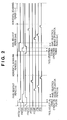
- Fig. 3 is a timing chart showing an operation example according to the preferred embodiment of the present invention.
- Fig. 4 is a circuit diagram showing a pixel arrangement according to a modification
- Fig. 5 is a circuit diagram showing a pixel arrangement according to another modification
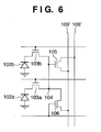
- Fig. 6 is a circuit diagram showing a pixel arrangement according to still another modification
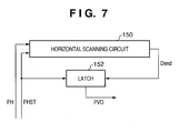
- Fig. 7 is a block diagram showing an arrangement of a control signal generation circuit for generating a control signal PVD in the solid-state image sensor
- Fig. 8 is a timing chart showing change of a signal in the control signal generation circuit illustrated in Fig. 7 ;
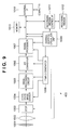
- Fig. 9 is a block diagram showing the configuration of an imaging system.
- FIG. 1 is a circuit diagram schematically showing the arrangement of a solid-state image sensor according to the preferred embodiment of the present invention.
- a solid-state image sensor 100 according to the preferred embodiment of the present invention comprises a pixel array 90 in which a plurality of pixels 101 are two-dimensionally arrayed, a vertical scanning circuit 140 which selects a row of the pixel array 90, and a horizontal scanning circuit 150 which selects a column of the pixel array 90.
- the solid-state image sensor 100 comprises column amplifiers 160 and capacitance units 170 which are arranged on respective columns of the pixel array 90.
- the solid-state image sensor 100 also comprises an output amplifier 120 which amplifies a signal input from the capacitance unit of a column selected by the horizontal scanning circuit 150.
- the pixel array 90 is made up of only four pixels 101 arranged on two rows and two columns.
- the actual pixel array 90 can be made up of a larger number of pixels 101.
- Each pixel 101 includes a photo-electric converter 102, transfer switch 103, amplifier 105, and control switch (reset switch) 106.
- the photo-electric converter 102 photoelectrically converts incident light into charges.
- the photo-electric converter 102 is typically formed from a photodiode.
- the transfer switch 103 transfers charges from the photo-electric converter 102 to a charge-voltage conversion node 104.
- the transfer switch 103 is typically formed from a MOS transistor.
- the transfer switch 103 transfers charges from the photo-electric converter 102 to the charge-voltage conversion node 104 in response to activation of a transfer pulse PTX driven by the vertical scanning circuit 140.
- the charge-voltage conversion node 104 has a capacitance, and converts charges into a voltage by this capacitance.
- the charge-voltage conversion node 104 typically includes a floating diffusion region (FD) formed in a semiconductor substrate.
- FD floating diffusion region
- the amplifier 105 outputs, to a vertical signal line 109 on a column to which the target pixel belongs, a signal corresponding to charges transferred to the charge-voltage conversion node 104.
- the amplifier 105 is typically formed from a MOS transistor (amplifier MOS transistor), and its gate is coupled to the charge-voltage conversion node 104.
- the control switch 106 controls or resets the voltage of the charge-voltage conversion node 104.
- the control switch 106 is typically formed from a MOS transistor (reset MOS transistor). The control switch 106 is turned on in response to activation of a reset signal PRES driven by the vertical scanning circuit 140, and controls the voltage of the charge-voltage conversion node 104.
- the pixel 101 is defined as a circuit including the photo-electric converter 102, transfer switch 103, charge-voltage conversion node 104, amplifier 105, and control switch 106. In this case, at least two pixels may also share at least one of the charge-voltage conversion node 104, amplifier 105, and control switch 106.
- the drain of an amplifier MOS transistor which forms the amplifier 105, and that of a reset MOS transistor which forms the control switch 106 are coupled to a voltage supplying line 108.
- the voltage of the voltage supplying line 108 is driven by a voltage controller 130.
- the vertical signal line 109 is coupled to a constant current source 110.
- a source follower circuit is made up of the constant current source 110, and an amplifier MOS transistor which forms the amplifier 105 of the pixel 101 belonging to a selected row.
- a lower column amplifier 160 in Fig. 1 amplifies a signal read out via the vertical signal line 109 on an odd-numbered column.
- An upper column amplifier 160 (not shown) in Fig. 1 amplifies a signal read out via the vertical signal line 109 on an even-numbered column.
- a voltage set at the charge-voltage conversion node 104 by the voltage controller 130 via the control switch 106 includes a first voltage VD_1 for setting a pixel in a selected state, and a second voltage VD_2 for setting the pixel in an unselected state.
- the voltage controller 130 and the control switch 106 of each pixel 101 set the voltage of the charge-voltage conversion node 104 of each pixel 101 to the second voltage VD_2 by using at least part of the horizontal scanning period.
- a voltage drop may occur across the MOS transistor when the voltage level upon activation of the reset signal PRES is lower by the threshold of the control switch 106 than that of the voltage supplying line 108.
- the voltage levels of the reset signal PRES and voltage supplying line 108 are determined to prevent the voltage drop.
- the first voltage VD_1 is set higher than the second voltage VD_2.
- the first voltage is set lower than the second voltage.
- the voltage controller 130 switches a voltage to be supplied to the voltage supplying line 108 between the first voltage VD_1 and the second voltage VD_2 in accordance with a voltage switching signal PVD.
- the voltage controller 130 includes, for example, a first transmission gate 131, second transmission gate 132, and inverter 133.
- the input of the first transmission gate 131 receives the first voltage VD_1, and that of the second transmission gate 132 receives the second voltage VD_2.
- the outputs of the first transmission gate 131 and second transmission gate 132 are coupled to the voltage supplying line 108.
- the voltage switching signal PVD is at high level, the first transmission gate 131 is ON, and the first voltage VD_1 is supplied to the voltage supplying line 108.
- the second transmission gate 132 is ON, and the second voltage VD_2 is supplied to the voltage supplying line 108.
- the column amplifier 160 includes, for example, a differential amplifier 112, input capacitance 113, feedback capacitance 114, and clamp control switch 115.
- the column amplifier 160 in this example can obtain an inverting gain at the ratio of the input capacitance 113 and feedback capacitance 114.
- a clamp pulse PCLMP changes to high level for only a predetermined period.
- a signal output from the column amplifier 160 becomes equal to a reference voltage VREF applied to the non-inverting input terminal of the differential amplifier 112.
- a write signal PTN changes to high level for only a predetermined period.
- the noise level (N output) corresponding to the reset state of the pixel 101 is written in a holding capacitance 118n via a write switch 117n.
- the transfer pulse PTX is activated to turn on the transfer switch 103 for only a predetermined period.
- charges in the photo-electric converter 102 are transferred to the charge-voltage conversion node 104 via the transfer switch 103.
- the amplifier 105 outputs, to the vertical signal line 109, a signal corresponding to the charges transferred to the charge-voltage conversion node 104.
- the column amplifier 160 outputs a signal level (S output) prepared by giving the above-mentioned inverting gain to a voltage change from the voltage at which the clamp pulse PCLMP is at low level.
- a write signal PTS changes to high level for only a predetermined period, and the signal level (S output) is written in a holding capacitance 118s via a write switch 117s.
- a pixel signal is output by horizontal scanning. That is, the noise level (N output) and signal level (S output) of a column sequentially selected by the horizontal scanning circuit 150 are output from the holding capacitances 118n and 118s to the output amplifier (differential amplifier) 120.
- the output amplifier (differential amplifier) 120 calculates and outputs the difference between the signal level (S output) and the noise level (N output).
- the vertical scanning circuit 140 scans selected rows, and the readout operation is repeated, obtaining readout outputs from all the rows of the pixel array 90.
- the power supply voltage can be set to, e.g., 3.3 V
- the high level of the first voltage VD_1 can be set to, e.g., 3.3 V
- the second voltage VD_2 can be set to, e.g., 0.3 V to 1.0 V.
- the operation of the solid-state image sensor 100 shown in Fig. 1 will be explained.
- a case where the charge-voltage conversion node 104 of the pixel 101 on an unselected row is reset during the pixel readout period (horizontal blanking period) will be described with reference to Fig. 2 .
- the pixel readout period is a period during which a signal is read out from the pixel array 90 by the column amplifier 160 via the vertical signal line 109, and stored in the capacitance unit 170, that is, a period between horizontal scanning periods.
- the pixel readout period is equivalent to the horizontal blanking period.
- PRES(n) and PRES(n+1) represent reset signals PRES for controlling pixels on the nth and (n+1)th rows driven by the vertical scanning circuit 140.
- PTX(n) and PTX(n+1) represent transfer pulses PTX for controlling pixels on the nth and (n+1)th rows driven by the vertical scanning circuit 140.
- all MOS transistors in the pixel 101 are NMOS transistors.
- the voltage switching signal PVD changes to low level to supply the selection disable second voltage VD_2 to the voltage supplying line 108.
- the vertical scanning circuit 140 activates the reset signals PRES(n) and PRES(n+1) for all rows to high level.
- the second voltage VD_2 is applied to the charge-voltage conversion nodes 104 of all pixels in the pixel array 90 via the voltage supplying lines 108 and control switches 106.
- the charge-voltage conversion nodes 104 of all pixels are reset to the second voltage VD_2.
- the reset signal PRES(n+1) for an unselected row changes to low level, and the control switches (reset switches) 106 of the pixels 101 on the unselected row are turned off.
- the voltage switching signal PVD changes to high level to supply the pixel selecting first voltage VD_1 to the voltage supplying line 108.
- the voltage of the voltage supplying line 108 changes to the first voltage VD_H.
- the reset signal PRES(n) for a selected row keeps high level.
- the first voltage VD_1 is applied via the voltage supplying lines 108 and control switches 106 to the charge-voltage conversion nodes 104 of the pixels 101 on the selected row.
- the charge-voltage conversion nodes 104 of the pixels 101 on the selected row are reset to the first voltage VD_1.
- the pixels 101 on the selected row output signals corresponding to the pixel reset state to the vertical signal lines 109.
- the clamp pulse PCLMP changes to high level for only a predetermined period. Thereafter, the clamp pulse PCLMP returns to low level, and the write signal PTN changes to high level for only a predetermined period.
- the noise level (N output) corresponding to the reset state of the pixel 101 is written in the holding capacitance 118n via the write switch 117n.
- the transfer pulse PTX(n) is activated to turn on the transfer switch 103 for only a predetermined period.
- charges in the photo-electric converter 102 are transferred to the charge-voltage conversion node 104 via the transfer switch 103.
- a signal corresponding to the charges is output to the vertical signal line 109.
- the column amplifier 160 outputs a signal level (S output) prepared by giving the above-mentioned inverting gain to a voltage change from the voltage at which the clamp pulse PCLMP is at low level.
- the write signal PTS changes to high level for only a predetermined period, and the signal level (S output) is written in the holding capacitance 118s via the write switch 117s.
- the horizontal scanning operation is done for the nth row. That is, the noise level (N output) and signal level (S output) of a column sequentially selected by the horizontal scanning circuit 150 are output from the holding capacitances 118n and 118s to the output amplifier (differential amplifier) 120.
- the output amplifier (differential amplifier) 120 calculates and outputs the difference between the signal level (S output) and the noise level (N output).
- the operation to set a row in an unselected state is executed during the horizontal blanking period. This prolongs the horizontal blanking period, which is disadvantageous to high-speed readout of a signal.
- the voltage switching signal PVD changes to low level to supply the selection disable second voltage VD_2 to the voltage supplying line 108 during at least part of the horizontal scanning period of pixels on the nth row.
- the vertical scanning circuit 140 activates the reset signals PRES(n) and PRES(n+1) for all rows to high level.
- the second voltage VD_2 is applied to the charge-voltage conversion nodes 104 of all pixels in the pixel array 90 via the voltage supplying lines 108 and control switches 106. That is, in at least part of the horizontal scanning period, the charge-voltage conversion nodes 104 of all pixels in the pixel array 90 are reset to the second voltage VD_2.
- the voltage switching signal PVD changes to high level to supply the pixel selecting first voltage VD_1 to the voltage supplying line 108.
- the reset signal PRES(n) for an unselected row is deactivated to low level, and the reset signal PRES(n+1) for a selected row is activated to high level for only a predetermined period.
- the control switches 106 of the pixels 101 on the unselected row are turned off, and those of the pixels 101 on the selected row are turned on for only a predetermined period.
- the charge-voltage conversion nodes 104 of the pixels 101 on the selected (n+1)th row receive the first voltage VD_1 via the voltage supplying lines 108 and control switches 106, and are reset to the first voltage VD_1.
- the clamp pulse PCLMP changes to high level for only a predetermined period. Then, the clamp pulse PCLMP returns to low level, and the write signal PTN changes to high level for only a predetermined period.
- the noise level (N output) corresponding to the reset state of the pixel 101 is written in the holding capacitance 118n via the write switch 117n.
- the transfer pulse PTX(n+1) is activated to turn on the transfer switch 103 for only a predetermined period.
- charges in the photo-electric converter 102 are transferred to the charge-voltage conversion node 104 via the transfer switch 103.
- a signal corresponding to the charges is output to the vertical signal line 109.
- the column amplifier 160 outputs a signal level (S output) prepared by giving the above-mentioned inverting gain to a voltage change from the voltage at which the clamp pulse PCLMP is at low level.
- the write signal PTS changes to high level for only a predetermined period, and the signal level (S output) is written in the holding capacitance 118s via the write switch 117s.
- the horizontal scanning operation is done for the (n+1)th row. That is, the noise level (N output) and signal level (S output) of a column sequentially selected by the horizontal scanning circuit 150 are output from the holding capacitances 118n and 118s to the output amplifier (differential amplifier) 120.
- the output amplifier (differential amplifier) 120 calculates and outputs the difference between the signal level (S output) and the noise level (N output).
- the horizontal blanking period can be shortened to read out a signal at higher speed as compared with the comparative example.
- the frame rate can increase.
- the control switch 106 of each pixel is ON from the start to the end of the entire horizontal scanning period.
- the voltage controller 130 drives the charge-voltage conversion node 104 of each pixel at the second voltage via the control switch 106 of the pixel. This can prevent the selection disable operation from interfering with horizontal scanning, more specifically, noise generated by the selection disable operation from mixing in the signal of a pixel on a specific column in the horizontal scanning period. Generation of fixed pattern noise can be prevented.
- the voltage switching signal PVD may also be supplied from outside the solid-state image sensor 100 or generated within the solid-state image sensor 100.
- the circuit arrangement can be simplified to reduce the chip size.
- the number of pads can be reduced to downsize the mounting board.
- Fig. 7 is a block diagram showing an arrangement of a control signal generation circuit for generating the control signal PVD in the solid-state image sensor 100.
- Fig. 8 is a timing chart showing change of a signal in the control signal generation circuit.
- the horizontal scanning circuit 150 is formed from a shift register.
- the horizontal scanning circuit 150 receives a scanning start signal PHST as a pulse signal in accordance with a scanning pulse (scanning clock) PH, and shifts the pulse signal in accordance with the scanning pulse (scanning clock) PH. After shifting the pulse signal to the final stage, the horizontal scanning circuit 150 outputs a scanning end signal Dend.
- a latch circuit 152 generates the voltage switching signal PVD which changes to high level in response to activation of the scanning start signal PHST and low level in response to activation of the scanning end signal Dend.
- Fig. 4 is a circuit diagram showing a pixel arrangement according to the first modification.
- the drain of the control switch (reset MOS transistor) 106 is coupled to a vertical signal line 109'.
- the voltage controller 130 suffices to drive the vertical signal line 109'. While a signal from the pixel 101 is output to the vertical signal line 109', the voltage controller 130 needs to be electrically disconnected from the vertical signal line 109'.
- the voltage of a voltage supplying line 108' coupled to the drain of the amplifier 105 is fixed.
- the present invention is also applicable to an arrangement in which a plurality of photo-electric converters 102 share at least one of the transfer switch 103, control switch 106, amplifier 105, and charge-voltage conversion node 104.
- two photo-electric converters 102a and 102b share the amplifier 105 and control switch 106.
- Transfer switches 103a and 103b are arranged in correspondence with the photo-electric converters 102a and 102b.
- two photo-electric converters 102a and 102b similarly share the amplifier 105 and control switch 106.
- Transfer switches 103a and 103b are arranged in correspondence with the photo-electric converters 102a and 102b.
- FIG. 9 is a block diagram showing the schematic configuration of an imaging system according to a preferred embodiment of the present invention.
- An imaging system 400 comprises the above-described solid-state image sensor 100.
- a lens 1002 forms an optical image of an object on the imaging plane of the solid-state image sensor 100.
- the outer surface of the lens 1002 is covered with a barrier 1001 which protects the lens 1002 and also serves as a main switch.
- the lens 1002 has a stop 1003 to adjust the quantity of light passing through the lens 1002.
- a signal processing circuit 1005 performs various processes such as correction and clamping for an imaging signal output from the solid-state image sensor 100.
- An A/D converter 1006 analog-to-digital-converts an imaging signal output from the signal processing circuit 1005.
- a signal processor 1007 performs various processes such as correction and data compression for image data output from the A/D converter 1006.
- the solid-state image sensor 100, signal processing circuit 1005, A/D converter 1006, and signal processor 1007 operate in accordance with timing signals generated by a timing generator 1008.
- the blocks 1005 to 1008 may also be formed on the same chip as that of the solid-state image sensor 100.
- An overall control/operation unit 1009 controls the blocks of the imaging system 400.
- the imaging system 400 comprises a memory 1010 for temporarily storing image data, and a recording medium control interface 1011 for recording/reading out an image on/from a recording medium.
- a recording medium 1012 includes a semiconductor memory and the like and is detachable.
- the imaging system 400 may comprise an external interface (I/F) 1013 for communicating with an external computer or the like.
- the overall control/operation unit 1009 sets the stop 1003 to the full-aperture state.
- a signal output from the solid-state image sensor 100 enters the A/D converter 1006 through the signal processing circuit 1005.
- the A/D converter 1006 A/D-converts the signal and outputs it to the signal processor 1007.
- the signal processor 1007 processes the data and supplies it to the overall control/operation unit 1009.
- the overall control/operation unit 1009 calculates and determines the exposure.
- the overall control/operation unit 1009 controls the stop based on the determined exposure.
- the overall control/operation unit 1009 extracts a high-frequency component from the signal which is output from the solid-state image sensor 100 and processed by the signal processor 1007.
- the overall control/operation unit 1009 calculates the distance to the object based on the high-frequency component.
- the overall control/operation unit 1009 drives the lens 1002 to determine whether the object is in focus. If the overall control/operation unit 1009 determines that the object is out of focus, it drives the lens 1002 again to calculate the distance.
- an imaging signal output from the solid-state image sensor 100 undergoes correction and the like by the signal processing circuit 1005, is A/D-converted by the A/D converter 1006, and is processed by the signal processor 1007.
- the image data processed by the signal processor 1007 is stored in the memory 1010 by the overall control/operation unit 1009.
- the image data stored in the memory 1010 is recorded on the recording medium 1012 via the recording medium control I/F under the control of the overall control/operation unit 1009.
- the image data can be provided to a computer or the like via the external I/F 1013 and processed by it.
- Each pixel includes a photo-electric converter, transfer switch, charge-voltage conversion node, amplifier, and control switch.
- a solid-state image sensor includes a voltage controller which controls the voltage of the charge-voltage conversion node of each pixel via the control switch of the pixel.
- a voltage set at the charge-voltage conversion node by the voltage controller via the control switch includes a first voltage (VD_1) for setting a pixel in a selected state, and a second voltage (VD_2) for setting the pixel in an unselected state.
- the voltage controller and the control switch of each pixel set the voltage of the charge-voltage conversion node of each pixel to the second voltage (VD_2) by using at least part of the horizontal scanning period.
Abstract
Description
- The present invention relates to a solid-state image sensor and an imaging system including it.
- Solid-state image sensors such as a CMOS image sensor have been studied to decrease the number of elements (e.g., MOS transistors) which form a pixel, in order to downsize the pixel. As one method,
Japanese Patent Laid-Open No. 2004-343529 Japanese Patent Laid-Open No. 2004-343529 - In the solid-state image sensor, the frame rate decreases as the readout period (horizontal blanking period) becomes longer. According to this pixel selection method, the FD voltage of pixels on a selected row needs to be set high, and that of pixels on an unselected row needs to be set low. Before reading out signals from pixels belonging to a selected row, a low voltage (selection disable voltage) needs to be applied to the FDs of all pixels. Then, a high voltage (selection enable voltage) needs to be applied to the FDs of pixels on a selected row.
- A relatively long time is taken to set the voltage of an entire voltage supplying line to a selection disable voltage level. If this time is long, this means that the pixel selection disable period occupies a large proportion of the time taken to read out signals from all pixels. This problem is more serious in an application requested of high frame rate or a case where the imaging plane becomes large to increase the resistance or parasitic capacitance of a voltage supplying line. In particular, the HD (High Definition) standard requires an output of 60 frames per sec, and strong demand has arisen for solving this problem.
- The present invention has been made to overcome the conventional drawbacks, and has as its object to provide a solid-state image sensor advantageous to high-speed readout of a signal.
- The present invention is realized, for example, on a solid-state image sensor as specified in
claims 1 to 6. - Furthermore, the present invention is realized, for example, on an imaging system as specified in claim 7.
- Further features of the present invention will become apparent from the following description of exemplary embodiments with reference to the attached drawings.
-
Fig. 1 is a circuit diagram schematically showing the arrangement of a solid-state image sensor according to a preferred embodiment of the present invention; -
Fig. 2 is a timing chart showing a comparative operation example; -
Fig. 3 is a timing chart showing an operation example according to the preferred embodiment of the present invention; -
Fig. 4 is a circuit diagram showing a pixel arrangement according to a modification; -
Fig. 5 is a circuit diagram showing a pixel arrangement according to another modification; -
Fig. 6 is a circuit diagram showing a pixel arrangement according to still another modification; -
Fig. 7 is a block diagram showing an arrangement of a control signal generation circuit for generating a control signal PVD in the solid-state image sensor; -
Fig. 8 is a timing chart showing change of a signal in the control signal generation circuit illustrated inFig. 7 ; and -
Fig. 9 is a block diagram showing the configuration of an imaging system. - A preferred embodiment of the present invention will be described below with reference to the accompanying drawings.
-
Fig. 1 is a circuit diagram schematically showing the arrangement of a solid-state image sensor according to the preferred embodiment of the present invention. A solid-state image sensor 100 according to the preferred embodiment of the present invention comprises apixel array 90 in which a plurality ofpixels 101 are two-dimensionally arrayed, avertical scanning circuit 140 which selects a row of thepixel array 90, and ahorizontal scanning circuit 150 which selects a column of thepixel array 90. The solid-state image sensor 100 comprisescolumn amplifiers 160 andcapacitance units 170 which are arranged on respective columns of thepixel array 90. The solid-state image sensor 100 also comprises anoutput amplifier 120 which amplifies a signal input from the capacitance unit of a column selected by thehorizontal scanning circuit 150. - In the example shown in
Fig. 1 , thepixel array 90 is made up of only fourpixels 101 arranged on two rows and two columns. Theactual pixel array 90 can be made up of a larger number ofpixels 101. Eachpixel 101 includes a photo-electric converter 102,transfer switch 103,amplifier 105, and control switch (reset switch) 106. - The photo-
electric converter 102 photoelectrically converts incident light into charges. The photo-electric converter 102 is typically formed from a photodiode. Thetransfer switch 103 transfers charges from the photo-electric converter 102 to a charge-voltage conversion node 104. Thetransfer switch 103 is typically formed from a MOS transistor. Thetransfer switch 103 transfers charges from the photo-electric converter 102 to the charge-voltage conversion node 104 in response to activation of a transfer pulse PTX driven by thevertical scanning circuit 140. The charge-voltage conversion node 104 has a capacitance, and converts charges into a voltage by this capacitance. The charge-voltage conversion node 104 typically includes a floating diffusion region (FD) formed in a semiconductor substrate. Theamplifier 105 outputs, to avertical signal line 109 on a column to which the target pixel belongs, a signal corresponding to charges transferred to the charge-voltage conversion node 104. Theamplifier 105 is typically formed from a MOS transistor (amplifier MOS transistor), and its gate is coupled to the charge-voltage conversion node 104. The control switch 106 controls or resets the voltage of the charge-voltage conversion node 104. Thecontrol switch 106 is typically formed from a MOS transistor (reset MOS transistor). Thecontrol switch 106 is turned on in response to activation of a reset signal PRES driven by thevertical scanning circuit 140, and controls the voltage of the charge-voltage conversion node 104. - The
pixel 101 is defined as a circuit including the photo-electric converter 102,transfer switch 103, charge-voltage conversion node 104,amplifier 105, andcontrol switch 106. In this case, at least two pixels may also share at least one of the charge-voltage conversion node 104,amplifier 105, andcontrol switch 106. - In the example shown in
Fig. 1 , the drain of an amplifier MOS transistor which forms theamplifier 105, and that of a reset MOS transistor which forms thecontrol switch 106 are coupled to avoltage supplying line 108. The voltage of thevoltage supplying line 108 is driven by avoltage controller 130. - The
vertical signal line 109 is coupled to a constantcurrent source 110. A source follower circuit is made up of the constantcurrent source 110, and an amplifier MOS transistor which forms theamplifier 105 of thepixel 101 belonging to a selected row. - In the example shown in
Fig. 1 , alower column amplifier 160 inFig. 1 amplifies a signal read out via thevertical signal line 109 on an odd-numbered column. An upper column amplifier 160 (not shown) inFig. 1 amplifies a signal read out via thevertical signal line 109 on an even-numbered column. - In the first embodiment, a voltage set at the charge-
voltage conversion node 104 by thevoltage controller 130 via thecontrol switch 106 includes a first voltage VD_1 for setting a pixel in a selected state, and a second voltage VD_2 for setting the pixel in an unselected state. Thevoltage controller 130 and thecontrol switch 106 of eachpixel 101 set the voltage of the charge-voltage conversion node 104 of eachpixel 101 to the second voltage VD_2 by using at least part of the horizontal scanning period. A voltage drop may occur across the MOS transistor when the voltage level upon activation of the reset signal PRES is lower by the threshold of thecontrol switch 106 than that of thevoltage supplying line 108. The voltage levels of the reset signal PRES andvoltage supplying line 108 are determined to prevent the voltage drop. - When the
amplifier 105 is formed from an NMOS transistor, the first voltage VD_1 is set higher than the second voltage VD_2. When theamplifier 105 is formed from a PMOS transistor, the first voltage is set lower than the second voltage. - The
voltage controller 130 switches a voltage to be supplied to thevoltage supplying line 108 between the first voltage VD_1 and the second voltage VD_2 in accordance with a voltage switching signal PVD. Thevoltage controller 130 includes, for example, afirst transmission gate 131,second transmission gate 132, andinverter 133. The input of thefirst transmission gate 131 receives the first voltage VD_1, and that of thesecond transmission gate 132 receives the second voltage VD_2. The outputs of thefirst transmission gate 131 andsecond transmission gate 132 are coupled to thevoltage supplying line 108. When the voltage switching signal PVD is at high level, thefirst transmission gate 131 is ON, and the first voltage VD_1 is supplied to thevoltage supplying line 108. When the voltage switching signal PVD is at low level, thesecond transmission gate 132 is ON, and the second voltage VD_2 is supplied to thevoltage supplying line 108. - The
column amplifier 160 includes, for example, adifferential amplifier 112,input capacitance 113,feedback capacitance 114, and clampcontrol switch 115. Thecolumn amplifier 160 in this example can obtain an inverting gain at the ratio of theinput capacitance 113 andfeedback capacitance 114. - While a noise level (N output) corresponding to the pixel reset state is output to the
vertical signal line 109, a clamp pulse PCLMP changes to high level for only a predetermined period. When the clamp pulse PCLMP is at high level, a signal output from thecolumn amplifier 160 becomes equal to a reference voltage VREF applied to the non-inverting input terminal of thedifferential amplifier 112. After the clamp pulse PCLMP returns to low level, a write signal PTN changes to high level for only a predetermined period. As a result, the noise level (N output) corresponding to the reset state of thepixel 101 is written in a holding capacitance 118n via awrite switch 117n. - Then, the transfer pulse PTX is activated to turn on the
transfer switch 103 for only a predetermined period. In response to this, charges in the photo-electric converter 102 are transferred to the charge-voltage conversion node 104 via thetransfer switch 103. Theamplifier 105 outputs, to thevertical signal line 109, a signal corresponding to the charges transferred to the charge-voltage conversion node 104. Thecolumn amplifier 160 outputs a signal level (S output) prepared by giving the above-mentioned inverting gain to a voltage change from the voltage at which the clamp pulse PCLMP is at low level. A write signal PTS changes to high level for only a predetermined period, and the signal level (S output) is written in a holdingcapacitance 118s via a write switch 117s. - In the horizontal scanning period, a pixel signal is output by horizontal scanning. That is, the noise level (N output) and signal level (S output) of a column sequentially selected by the
horizontal scanning circuit 150 are output from the holdingcapacitances 118n and 118s to the output amplifier (differential amplifier) 120. The output amplifier (differential amplifier) 120 calculates and outputs the difference between the signal level (S output) and the noise level (N output). - The
vertical scanning circuit 140 scans selected rows, and the readout operation is repeated, obtaining readout outputs from all the rows of thepixel array 90. - Note that the power supply voltage can be set to, e.g., 3.3 V, the high level of the first voltage VD_1 can be set to, e.g., 3.3 V, and the second voltage VD_2 can be set to, e.g., 0.3 V to 1.0 V.
- The operation of the solid-
state image sensor 100 shown inFig. 1 will be explained. As a comparative example, a case where the charge-voltage conversion node 104 of thepixel 101 on an unselected row is reset during the pixel readout period (horizontal blanking period) will be described with reference toFig. 2 . The pixel readout period is a period during which a signal is read out from thepixel array 90 by thecolumn amplifier 160 via thevertical signal line 109, and stored in thecapacitance unit 170, that is, a period between horizontal scanning periods. Hence, the pixel readout period is equivalent to the horizontal blanking period. - PRES(n) and PRES(n+1) represent reset signals PRES for controlling pixels on the nth and (n+1)th rows driven by the
vertical scanning circuit 140. PTX(n) and PTX(n+1) represent transfer pulses PTX for controlling pixels on the nth and (n+1)th rows driven by thevertical scanning circuit 140. Assume that all MOS transistors in thepixel 101 are NMOS transistors. - In the pixel selection disable operation period, the voltage switching signal PVD changes to low level to supply the selection disable second voltage VD_2 to the
voltage supplying line 108. Thevertical scanning circuit 140 activates the reset signals PRES(n) and PRES(n+1) for all rows to high level. In response to this, the second voltage VD_2 is applied to the charge-voltage conversion nodes 104 of all pixels in thepixel array 90 via thevoltage supplying lines 108 and control switches 106. The charge-voltage conversion nodes 104 of all pixels are reset to the second voltage VD_2. - In the pixel selection enable operation period, the reset signal PRES(n+1) for an unselected row changes to low level, and the control switches (reset switches) 106 of the
pixels 101 on the unselected row are turned off. The voltage switching signal PVD changes to high level to supply the pixel selecting first voltage VD_1 to thevoltage supplying line 108. Then, the voltage of thevoltage supplying line 108 changes to the first voltage VD_H. At this time, the reset signal PRES(n) for a selected row keeps high level. Thus, the first voltage VD_1 is applied via thevoltage supplying lines 108 andcontrol switches 106 to the charge-voltage conversion nodes 104 of thepixels 101 on the selected row. The charge-voltage conversion nodes 104 of thepixels 101 on the selected row are reset to the first voltage VD_1. At this time, thepixels 101 on the selected row output signals corresponding to the pixel reset state to the vertical signal lines 109. - As described above, while a signal (reset signal) corresponding to the pixel reset state of each
pixel 101 on the nth row is output to thevertical signal line 109, the clamp pulse PCLMP changes to high level for only a predetermined period. Thereafter, the clamp pulse PCLMP returns to low level, and the write signal PTN changes to high level for only a predetermined period. The noise level (N output) corresponding to the reset state of thepixel 101 is written in the holding capacitance 118n via thewrite switch 117n. - Then, the transfer pulse PTX(n) is activated to turn on the
transfer switch 103 for only a predetermined period. In response to this, charges in the photo-electric converter 102 are transferred to the charge-voltage conversion node 104 via thetransfer switch 103. A signal corresponding to the charges is output to thevertical signal line 109. Thecolumn amplifier 160 outputs a signal level (S output) prepared by giving the above-mentioned inverting gain to a voltage change from the voltage at which the clamp pulse PCLMP is at low level. The write signal PTS changes to high level for only a predetermined period, and the signal level (S output) is written in the holdingcapacitance 118s via the write switch 117s. - In the horizontal scanning period, the horizontal scanning operation is done for the nth row. That is, the noise level (N output) and signal level (S output) of a column sequentially selected by the
horizontal scanning circuit 150 are output from the holdingcapacitances 118n and 118s to the output amplifier (differential amplifier) 120. The output amplifier (differential amplifier) 120 calculates and outputs the difference between the signal level (S output) and the noise level (N output). - According to this comparative example, the operation to set a row in an unselected state is executed during the horizontal blanking period. This prolongs the horizontal blanking period, which is disadvantageous to high-speed readout of a signal.
- As an operation example in the preferred embodiment of the present invention, a case where the charge-
voltage conversion node 104 of thepixel 101 on an unselected row is reset during the horizontal scanning period will be described with reference toFig. 3 . - In the preferred embodiment of the present invention, as illustrated in
Fig. 3 , the voltage switching signal PVD changes to low level to supply the selection disable second voltage VD_2 to thevoltage supplying line 108 during at least part of the horizontal scanning period of pixels on the nth row. Thevertical scanning circuit 140 activates the reset signals PRES(n) and PRES(n+1) for all rows to high level. In response to this, the second voltage VD_2 is applied to the charge-voltage conversion nodes 104 of all pixels in thepixel array 90 via thevoltage supplying lines 108 and control switches 106. That is, in at least part of the horizontal scanning period, the charge-voltage conversion nodes 104 of all pixels in thepixel array 90 are reset to the second voltage VD_2. - In the subsequent pixel readout period of the (n+1)th row, the voltage switching signal PVD changes to high level to supply the pixel selecting first voltage VD_1 to the
voltage supplying line 108. In the pixel readout period of the (n+1)th row, the reset signal PRES(n) for an unselected row is deactivated to low level, and the reset signal PRES(n+1) for a selected row is activated to high level for only a predetermined period. Then, the control switches 106 of thepixels 101 on the unselected row are turned off, and those of thepixels 101 on the selected row are turned on for only a predetermined period. The charge-voltage conversion nodes 104 of thepixels 101 on the selected (n+1)th row receive the first voltage VD_1 via thevoltage supplying lines 108 andcontrol switches 106, and are reset to the first voltage VD_1. - As described above, while a signal (reset signal) corresponding to the pixel reset state of each
pixel 101 on the (n+1)th row is output to thevertical signal line 109, the clamp pulse PCLMP changes to high level for only a predetermined period. Then, the clamp pulse PCLMP returns to low level, and the write signal PTN changes to high level for only a predetermined period. The noise level (N output) corresponding to the reset state of thepixel 101 is written in the holding capacitance 118n via thewrite switch 117n. - After that, the transfer pulse PTX(n+1) is activated to turn on the
transfer switch 103 for only a predetermined period. In response to this, charges in the photo-electric converter 102 are transferred to the charge-voltage conversion node 104 via thetransfer switch 103. A signal corresponding to the charges is output to thevertical signal line 109. Thecolumn amplifier 160 outputs a signal level (S output) prepared by giving the above-mentioned inverting gain to a voltage change from the voltage at which the clamp pulse PCLMP is at low level. The write signal PTS changes to high level for only a predetermined period, and the signal level (S output) is written in the holdingcapacitance 118s via the write switch 117s. - In the horizontal scanning period, the horizontal scanning operation is done for the (n+1)th row. That is, the noise level (N output) and signal level (S output) of a column sequentially selected by the
horizontal scanning circuit 150 are output from the holdingcapacitances 118n and 118s to the output amplifier (differential amplifier) 120. The output amplifier (differential amplifier) 120 calculates and outputs the difference between the signal level (S output) and the noise level (N output). - By resetting the charge-
voltage conversion node 104 of thepixel 101 on an unselected row during the horizontal scanning period, the horizontal blanking period can be shortened to read out a signal at higher speed as compared with the comparative example. As a result, for example, the frame rate can increase. - In the example shown in
Fig. 3 , thecontrol switch 106 of each pixel is ON from the start to the end of the entire horizontal scanning period. During the entire period, thevoltage controller 130 drives the charge-voltage conversion node 104 of each pixel at the second voltage via thecontrol switch 106 of the pixel. This can prevent the selection disable operation from interfering with horizontal scanning, more specifically, noise generated by the selection disable operation from mixing in the signal of a pixel on a specific column in the horizontal scanning period. Generation of fixed pattern noise can be prevented. - The voltage switching signal PVD may also be supplied from outside the solid-
state image sensor 100 or generated within the solid-state image sensor 100. In the former case, the circuit arrangement can be simplified to reduce the chip size. In the latter case, the number of pads can be reduced to downsize the mounting board. -
Fig. 7 is a block diagram showing an arrangement of a control signal generation circuit for generating the control signal PVD in the solid-state image sensor 100.Fig. 8 is a timing chart showing change of a signal in the control signal generation circuit. Thehorizontal scanning circuit 150 is formed from a shift register. Thehorizontal scanning circuit 150 receives a scanning start signal PHST as a pulse signal in accordance with a scanning pulse (scanning clock) PH, and shifts the pulse signal in accordance with the scanning pulse (scanning clock) PH. After shifting the pulse signal to the final stage, thehorizontal scanning circuit 150 outputs a scanning end signal Dend. Alatch circuit 152 generates the voltage switching signal PVD which changes to high level in response to activation of the scanning start signal PHST and low level in response to activation of the scanning end signal Dend. - In the
pixel 101 illustrated inFig. 1 , thevoltage supplying line 108 is commonly coupled to the drains of the control switch (reset MOS transistor) 106 and amplifier (amplifier MOS transistor) 105. Instead of this arrangement, the present invention can also adopt the following modification.Fig. 4 is a circuit diagram showing a pixel arrangement according to the first modification. In this modification, the drain of the control switch (reset MOS transistor) 106 is coupled to a vertical signal line 109'. In this arrangement example, thevoltage controller 130 suffices to drive the vertical signal line 109'. While a signal from thepixel 101 is output to the vertical signal line 109', thevoltage controller 130 needs to be electrically disconnected from the vertical signal line 109'. The voltage of a voltage supplying line 108' coupled to the drain of theamplifier 105 is fixed. - The present invention is also applicable to an arrangement in which a plurality of photo-
electric converters 102 share at least one of thetransfer switch 103,control switch 106,amplifier 105, and charge-voltage conversion node 104. - In the second modification shown in
Fig. 5 , two photo-electric converters amplifier 105 andcontrol switch 106.Transfer switches electric converters - Also in the third modification shown in
Fig. 6 , two photo-electric converters amplifier 105 andcontrol switch 106.Transfer switches electric converters -
Fig. 9 is a block diagram showing the schematic configuration of an imaging system according to a preferred embodiment of the present invention. Animaging system 400 comprises the above-described solid-state image sensor 100. - A
lens 1002 forms an optical image of an object on the imaging plane of the solid-state image sensor 100. The outer surface of thelens 1002 is covered with abarrier 1001 which protects thelens 1002 and also serves as a main switch. Thelens 1002 has astop 1003 to adjust the quantity of light passing through thelens 1002. Asignal processing circuit 1005 performs various processes such as correction and clamping for an imaging signal output from the solid-state image sensor 100. An A/D converter 1006 analog-to-digital-converts an imaging signal output from thesignal processing circuit 1005. Asignal processor 1007 performs various processes such as correction and data compression for image data output from the A/D converter 1006. The solid-state image sensor 100,signal processing circuit 1005, A/D converter 1006, andsignal processor 1007 operate in accordance with timing signals generated by atiming generator 1008. - The
blocks 1005 to 1008 may also be formed on the same chip as that of the solid-state image sensor 100. An overall control/operation unit 1009 controls the blocks of theimaging system 400. Theimaging system 400 comprises amemory 1010 for temporarily storing image data, and a recordingmedium control interface 1011 for recording/reading out an image on/from a recording medium. Arecording medium 1012 includes a semiconductor memory and the like and is detachable. Theimaging system 400 may comprise an external interface (I/F) 1013 for communicating with an external computer or the like. - The operation of the
imaging system 400 shown inFig. 9 will be described. In response to opening of thebarrier 1001, the main power supply, the power supply of the control system, and the power supply of the imaging circuit including the A/D converter 1006 are sequentially turned on. To control the exposure, the overall control/operation unit 1009 sets thestop 1003 to the full-aperture state. A signal output from the solid-state image sensor 100 enters the A/D converter 1006 through thesignal processing circuit 1005. The A/D converter 1006 A/D-converts the signal and outputs it to thesignal processor 1007. Thesignal processor 1007 processes the data and supplies it to the overall control/operation unit 1009. The overall control/operation unit 1009 calculates and determines the exposure. The overall control/operation unit 1009 controls the stop based on the determined exposure. - The overall control/
operation unit 1009 extracts a high-frequency component from the signal which is output from the solid-state image sensor 100 and processed by thesignal processor 1007. The overall control/operation unit 1009 calculates the distance to the object based on the high-frequency component. The overall control/operation unit 1009 drives thelens 1002 to determine whether the object is in focus. If the overall control/operation unit 1009 determines that the object is out of focus, it drives thelens 1002 again to calculate the distance. - After confirming that the object is in focus, actual exposure starts. After the end of exposure, an imaging signal output from the solid-
state image sensor 100 undergoes correction and the like by thesignal processing circuit 1005, is A/D-converted by the A/D converter 1006, and is processed by thesignal processor 1007. The image data processed by thesignal processor 1007 is stored in thememory 1010 by the overall control/operation unit 1009. - The image data stored in the
memory 1010 is recorded on therecording medium 1012 via the recording medium control I/F under the control of the overall control/operation unit 1009. The image data can be provided to a computer or the like via the external I/F 1013 and processed by it. - While the present invention has been described with reference to exemplary embodiments, it is to be understood that the invention is not limited to the disclosed exemplary embodiments. The scope of the following claims is to be accorded the broadest interpretation so as to encompass all such modifications and equivalent structures and functions.
Each pixel includes a photo-electric converter, transfer switch, charge-voltage conversion node, amplifier, and control switch. A solid-state image sensor includes a voltage controller which controls the voltage of the charge-voltage conversion node of each pixel via the control switch of the pixel. A voltage set at the charge-voltage conversion node by the voltage controller via the control switch includes a first voltage (VD_1) for setting a pixel in a selected state, and a second voltage (VD_2) for setting the pixel in an unselected state. The voltage controller and the control switch of each pixel set the voltage of the charge-voltage conversion node of each pixel to the second voltage (VD_2) by using at least part of the horizontal scanning period.
Claims (7)
- A solid-state image sensor including a pixel array in which a plurality of pixels are two-dimensionally arrayed, a vertical scanning circuit which selects a row of the pixel array, and a horizontal scanning circuit which selects a column of the pixel array, each pixel including a photo-electric converter, a transfer switch which transfers charges from the photo-electric converter to a charge-voltage conversion node, an amplifier which outputs, to a vertical signal line of a column to which the pixel belongs, a signal corresponding to the charges transferred to the charge-voltage conversion node, and a control switch which controls a voltage of the charge-voltage conversion node, the sensor characterized by comprising
a voltage controller which controls the voltage of the charge-voltage conversion node of each pixel via the control switch of each pixel,
wherein a voltage set at the charge-voltage conversion node by said voltage controller via the control switch includes a first voltage for setting a pixel in a selected state, and a second voltage for setting the pixel in an unselected state, and
said voltage controller and the control switch of each pixel set the voltage of the charge-voltage conversion node of each pixel to the second voltage by using at least part of a horizontal scanning period. - The sensor according to claim 1, characterized in that the control switch is formed from a reset MOS transistor.
- The sensor according to claim 2, characterized in that the amplifier is formed from an amplifier MOS transistor, and a drain of the amplifier MOS transistor and a drain of the reset MOS transistor which are arranged in one pixel are electrically coupled.
- The sensor according to claim 2, characterized in that the amplifier is formed from an amplifier MOS transistor, and a source of the amplifier MOS transistor and a drain of the reset MOS transistor which are arranged in one pixel are electrically coupled.
- The sensor according to any one of claims 1 to 4, characterized in that at least two pixels share at least one of one amplifier, one charge-voltage conversion node, and one control switch.
- The sensor according to any one of claims 1 to 5, characterized in that the control switch of each pixel is turned on from a start to end of the entire horizontal scanning period, and said voltage controller drives the charge-voltage conversion node of each pixel at the second voltage via the control switch of each pixel in the entire period.
- An imaging system characterized by comprising:a solid-state image sensor defined in any one of claims 1 to 6; anda signal processing circuit which processes a signal output from said solid-state image sensor.
Applications Claiming Priority (1)
| Application Number | Priority Date | Filing Date | Title |
|---|---|---|---|
| JP2006356089A JP4979375B2 (en) | 2006-12-28 | 2006-12-28 | Solid-state imaging device and imaging system |
Publications (3)
| Publication Number | Publication Date |
|---|---|
| EP1940148A2 true EP1940148A2 (en) | 2008-07-02 |
| EP1940148A3 EP1940148A3 (en) | 2010-07-28 |
| EP1940148B1 EP1940148B1 (en) | 2012-12-19 |
Family
ID=39226923
Family Applications (1)
| Application Number | Title | Priority Date | Filing Date |
|---|---|---|---|
| EP07150433A Not-in-force EP1940148B1 (en) | 2006-12-28 | 2007-12-27 | Solid-state image sensor and imaging system |
Country Status (4)
| Country | Link |
|---|---|
| US (2) | US7825974B2 (en) |
| EP (1) | EP1940148B1 (en) |
| JP (1) | JP4979375B2 (en) |
| CN (1) | CN101212581B (en) |
Cited By (1)
| Publication number | Priority date | Publication date | Assignee | Title |
|---|---|---|---|---|
| US8451360B2 (en) | 2009-05-19 | 2013-05-28 | Canon Kabushiki Kaisha | Solid-state imaging apparatus for selectively outputting signals from pixels therein |
Families Citing this family (47)
| Publication number | Priority date | Publication date | Assignee | Title |
|---|---|---|---|---|
| JP4818018B2 (en) * | 2006-08-01 | 2011-11-16 | キヤノン株式会社 | Photoelectric conversion device and imaging system using the same |
| JP5110820B2 (en) | 2006-08-02 | 2012-12-26 | キヤノン株式会社 | Photoelectric conversion device, photoelectric conversion device manufacturing method, and imaging system |
| JP4979375B2 (en) * | 2006-12-28 | 2012-07-18 | キヤノン株式会社 | Solid-state imaging device and imaging system |
| JP2009021809A (en) * | 2007-07-11 | 2009-01-29 | Canon Inc | Driving method of imaging device, imaging device, and imaging system |
| JP4548519B2 (en) * | 2007-10-16 | 2010-09-22 | セイコーエプソン株式会社 | Light source device |
| JP5164531B2 (en) | 2007-11-13 | 2013-03-21 | キヤノン株式会社 | Solid-state imaging device |
| JP5366396B2 (en) * | 2007-12-28 | 2013-12-11 | キヤノン株式会社 | Photoelectric conversion device manufacturing method, semiconductor device manufacturing method, photoelectric conversion device, and imaging system |
| JP5014114B2 (en) | 2007-12-28 | 2012-08-29 | キヤノン株式会社 | Imaging apparatus and imaging system |
| JP5111140B2 (en) * | 2008-02-06 | 2012-12-26 | キヤノン株式会社 | Solid-state imaging device driving method, solid-state imaging device, and imaging system |
| JP4685120B2 (en) * | 2008-02-13 | 2011-05-18 | キヤノン株式会社 | Photoelectric conversion device and imaging system |
| JP5371463B2 (en) | 2008-02-28 | 2013-12-18 | キヤノン株式会社 | IMAGING DEVICE, IMAGING SYSTEM, AND IMAGING DEVICE CONTROL METHOD |
| JP5102115B2 (en) * | 2008-06-05 | 2012-12-19 | キヤノン株式会社 | Imaging apparatus and imaging system |
| JP5317591B2 (en) * | 2008-09-01 | 2013-10-16 | キヤノン株式会社 | Imaging device |
| JP5374110B2 (en) * | 2008-10-22 | 2013-12-25 | キヤノン株式会社 | Imaging sensor and imaging apparatus |
| JP5203913B2 (en) * | 2008-12-15 | 2013-06-05 | キヤノン株式会社 | Photoelectric conversion device, imaging system, and driving method of photoelectric conversion device |
| JP5262743B2 (en) * | 2009-01-20 | 2013-08-14 | セイコーエプソン株式会社 | Projection display apparatus, control method therefor, and control program therefor |
| JP2011004390A (en) | 2009-05-18 | 2011-01-06 | Canon Inc | Imaging device, imaging system, and method for driving imaging device |
| CN102143332B (en) * | 2011-04-20 | 2013-03-20 | 中国科学院半导体研究所 | Standard complementary metal oxide semiconductor (CMOS) process-based color image sensor |
| JP5762199B2 (en) | 2011-07-28 | 2015-08-12 | キヤノン株式会社 | Solid-state imaging device |
| JP5901186B2 (en) | 2011-09-05 | 2016-04-06 | キヤノン株式会社 | Solid-state imaging device and driving method thereof |
| JP5858695B2 (en) | 2011-09-08 | 2016-02-10 | キヤノン株式会社 | Solid-state imaging device and driving method of solid-state imaging device |
| JP5801665B2 (en) | 2011-09-15 | 2015-10-28 | キヤノン株式会社 | Solid-state imaging device, A / D converter and control method thereof |
| JP5806566B2 (en) | 2011-09-15 | 2015-11-10 | キヤノン株式会社 | A / D converter and solid-state imaging device |
| JP5484422B2 (en) | 2011-10-07 | 2014-05-07 | キヤノン株式会社 | Solid-state imaging device |
| JP5901212B2 (en) | 2011-10-07 | 2016-04-06 | キヤノン株式会社 | Photoelectric conversion system |
| JP5930651B2 (en) | 2011-10-07 | 2016-06-08 | キヤノン株式会社 | Solid-state imaging device |
| JP6071183B2 (en) | 2011-10-20 | 2017-02-01 | キヤノン株式会社 | Solid-state imaging device and camera |
| JP5887827B2 (en) * | 2011-10-20 | 2016-03-16 | ソニー株式会社 | Solid-state imaging device and camera system |
| JP2013157883A (en) * | 2012-01-31 | 2013-08-15 | Sony Corp | Solid-state imaging device and camera system |
| JP5886806B2 (en) | 2013-09-17 | 2016-03-16 | キヤノン株式会社 | Solid-state imaging device |
| JP6245997B2 (en) | 2014-01-16 | 2017-12-13 | キヤノン株式会社 | Solid-state imaging device and imaging system |
| JP6057931B2 (en) | 2014-02-10 | 2017-01-11 | キヤノン株式会社 | Photoelectric conversion device and imaging system using the same |
| JP6548391B2 (en) | 2014-03-31 | 2019-07-24 | キヤノン株式会社 | Photoelectric conversion device and imaging system |
| CN106031158A (en) * | 2014-07-07 | 2016-10-12 | 奥林巴斯株式会社 | Imaging device |
| JP6436953B2 (en) | 2016-09-30 | 2018-12-12 | キヤノン株式会社 | Solid-state imaging device, driving method thereof, and imaging system |
| JP6552478B2 (en) | 2016-12-28 | 2019-07-31 | キヤノン株式会社 | Solid-state imaging device |
| US10652531B2 (en) | 2017-01-25 | 2020-05-12 | Canon Kabushiki Kaisha | Solid-state imaging device, imaging system, and movable object |
| JP2019087939A (en) | 2017-11-09 | 2019-06-06 | キヤノン株式会社 | Photoelectric conversion device, electronic equipment, conveyance apparatus and drive method of photoelectric conversion device |
| JP6704893B2 (en) | 2017-11-30 | 2020-06-03 | キヤノン株式会社 | Solid-state imaging device, imaging system, and method for driving solid-state imaging device |
| US11233962B2 (en) * | 2018-06-27 | 2022-01-25 | Samsung Electronics Co., Ltd. | Image sensor and pixel array which operate based on a clamp voltage and a selection voltage, and operation method of the image sensor |
| KR102573304B1 (en) | 2018-06-27 | 2023-08-31 | 삼성전자 주식회사 | Image sensor, pixel array and operation method thereof |
| CN111565032B (en) * | 2019-02-13 | 2023-11-10 | 上海耕岩智能科技有限公司 | Signal conversion circuit and signal readout circuit architecture |
| JP7374639B2 (en) | 2019-07-19 | 2023-11-07 | キヤノン株式会社 | Photoelectric conversion device and imaging system |
| JP7303682B2 (en) | 2019-07-19 | 2023-07-05 | キヤノン株式会社 | Photoelectric conversion device and imaging system |
| US11140344B2 (en) * | 2019-08-21 | 2021-10-05 | Semiconductor Components Industries, Llc | Imaging systems with improved circuitry to provide boosted control signals |
| JP2021136634A (en) | 2020-02-28 | 2021-09-13 | キヤノン株式会社 | Imaging device and imaging system |
| CN114866708A (en) | 2021-02-04 | 2022-08-05 | 佳能株式会社 | Photoelectric conversion device, A/D converter, and apparatus |
Citations (2)
| Publication number | Priority date | Publication date | Assignee | Title |
|---|---|---|---|---|
| US20050023532A1 (en) | 2003-05-16 | 2005-02-03 | Keiji Mabuchi | Solid-state imaging device, method of driving same, and camera apparatus |
| US20060175536A1 (en) | 2005-02-07 | 2006-08-10 | Samsung Electronics Co., Ltd. | CMOS sensor array with a shared structure |
Family Cites Families (21)
| Publication number | Priority date | Publication date | Assignee | Title |
|---|---|---|---|---|
| US6320616B1 (en) * | 1997-06-02 | 2001-11-20 | Sarnoff Corporation | CMOS image sensor with reduced fixed pattern noise |
| JP3466886B2 (en) * | 1997-10-06 | 2003-11-17 | キヤノン株式会社 | Solid-state imaging device |
| JP4200545B2 (en) * | 1998-06-08 | 2008-12-24 | ソニー株式会社 | Solid-state imaging device, driving method thereof, and camera system |
| US6043478A (en) * | 1998-06-25 | 2000-03-28 | Industrial Technology Research Institute | Active pixel sensor with shared readout structure |
| WO2003054922A2 (en) * | 2001-12-21 | 2003-07-03 | Koninklijke Philips Electronics N.V. | Image pick-up device and camera system comprising an image pick-up device |
| JP3988189B2 (en) * | 2002-11-20 | 2007-10-10 | ソニー株式会社 | Solid-state imaging device |
| JP4355148B2 (en) | 2003-02-28 | 2009-10-28 | パナソニック株式会社 | Driving method of solid-state imaging device |
| JP4231322B2 (en) * | 2003-04-08 | 2009-02-25 | パナソニック株式会社 | Solid-state imaging device and imaging method |
| JP4297416B2 (en) | 2003-06-10 | 2009-07-15 | シャープ株式会社 | Solid-state imaging device, driving method thereof and camera |
| JP3951994B2 (en) | 2003-09-16 | 2007-08-01 | ソニー株式会社 | Solid-state imaging device and camera system |
| DE602004017969D1 (en) * | 2004-06-05 | 2009-01-08 | St Microelectronics Res & Dev | Image sensor with split reset signals and line selection |
| US20060102827A1 (en) * | 2004-11-17 | 2006-05-18 | Matsushita Electric Industrial Co., Ltd. | Solid-state imaging device |
| JP2006148328A (en) | 2004-11-17 | 2006-06-08 | Matsushita Electric Ind Co Ltd | Solid-state imaging apparatus |
| US20060203114A1 (en) | 2005-03-08 | 2006-09-14 | Eastman Kodak Company | Three-transistor CMOS active pixel |
| JP4340660B2 (en) * | 2005-04-14 | 2009-10-07 | シャープ株式会社 | Amplification type solid-state imaging device |
| JP4818018B2 (en) * | 2006-08-01 | 2011-11-16 | キヤノン株式会社 | Photoelectric conversion device and imaging system using the same |
| JP4956084B2 (en) * | 2006-08-01 | 2012-06-20 | キヤノン株式会社 | Photoelectric conversion device and imaging system using the same |
| JP4185949B2 (en) * | 2006-08-08 | 2008-11-26 | キヤノン株式会社 | Photoelectric conversion device and imaging device |
| JP4979375B2 (en) * | 2006-12-28 | 2012-07-18 | キヤノン株式会社 | Solid-state imaging device and imaging system |
| JP4058459B1 (en) * | 2007-03-02 | 2008-03-12 | キヤノン株式会社 | Imaging apparatus and imaging system |
| TWI433307B (en) * | 2008-10-22 | 2014-04-01 | Sony Corp | Solid state image sensor, method for driving a solid state image sensor, imaging apparatus, and electronic device |
-
2006
- 2006-12-28 JP JP2006356089A patent/JP4979375B2/en not_active Expired - Fee Related
-
2007
- 2007-12-20 US US11/960,886 patent/US7825974B2/en not_active Expired - Fee Related
- 2007-12-27 EP EP07150433A patent/EP1940148B1/en not_active Not-in-force
- 2007-12-28 CN CN200710300480.3A patent/CN101212581B/en not_active Expired - Fee Related
-
2010
- 2010-09-23 US US12/888,503 patent/US8063967B2/en not_active Expired - Fee Related
Patent Citations (2)
| Publication number | Priority date | Publication date | Assignee | Title |
|---|---|---|---|---|
| US20050023532A1 (en) | 2003-05-16 | 2005-02-03 | Keiji Mabuchi | Solid-state imaging device, method of driving same, and camera apparatus |
| US20060175536A1 (en) | 2005-02-07 | 2006-08-10 | Samsung Electronics Co., Ltd. | CMOS sensor array with a shared structure |
Cited By (1)
| Publication number | Priority date | Publication date | Assignee | Title |
|---|---|---|---|---|
| US8451360B2 (en) | 2009-05-19 | 2013-05-28 | Canon Kabushiki Kaisha | Solid-state imaging apparatus for selectively outputting signals from pixels therein |
Also Published As
| Publication number | Publication date |
|---|---|
| CN101212581B (en) | 2012-12-12 |
| US8063967B2 (en) | 2011-11-22 |
| US20110013042A1 (en) | 2011-01-20 |
| JP4979375B2 (en) | 2012-07-18 |
| EP1940148B1 (en) | 2012-12-19 |
| US7825974B2 (en) | 2010-11-02 |
| CN101212581A (en) | 2008-07-02 |
| US20080158403A1 (en) | 2008-07-03 |
| JP2008167281A (en) | 2008-07-17 |
| EP1940148A3 (en) | 2010-07-28 |
Similar Documents
| Publication | Publication Date | Title |
|---|---|---|
| EP1940148B1 (en) | Solid-state image sensor and imaging system | |
| KR101186734B1 (en) | Solid?state imaging device, camera and driving method thereof | |
| US7787037B2 (en) | Imaging method that continuously outputs a signal based on electric charges generated by a selected pixel unit without performing an operation of deselecting the selected pixel unit | |
| US8305473B2 (en) | Driving method of solid-state imaging apparatus, solid-state imaging apparatus, and imaging system | |
| US8023025B2 (en) | Photoelectric conversion apparatus and image pickup system using the same | |
| US8212905B2 (en) | Photoelectric conversion device, imaging system, and photoelectric conversion device driving method | |
| US20090122172A1 (en) | Solid-state imaging apparatus | |
| JP6172608B2 (en) | Solid-state imaging device, driving method thereof, and imaging device | |
| JP4967489B2 (en) | Solid-state imaging device | |
| JP2009077098A (en) | Solid-state imaging element and drive system thereof | |
| JP2008124237A (en) | Imaging apparatus, and camera | |
| US8300122B2 (en) | Solid-state imaging device, camera system, and signal reading method | |
| US8384008B2 (en) | Solid state imaging device to reduce power consumption | |
| JP2008042675A (en) | Photoelectric conversion device and imaging apparatus | |
| JP2011091474A (en) | Solid-state imaging apparatus and imaging apparatus | |
| JP5142694B2 (en) | Imaging device, driving method of imaging device, and imaging system |
Legal Events
| Date | Code | Title | Description |
|---|---|---|---|
| PUAI | Public reference made under article 153(3) epc to a published international application that has entered the european phase |
Free format text: ORIGINAL CODE: 0009012 |
|
| AK | Designated contracting states |
Kind code of ref document: A2 Designated state(s): AT BE BG CH CY CZ DE DK EE ES FI FR GB GR HU IE IS IT LI LT LU LV MC MT NL PL PT RO SE SI SK TR |
|
| AX | Request for extension of the european patent |
Extension state: AL BA HR MK RS |
|
| PUAL | Search report despatched |
Free format text: ORIGINAL CODE: 0009013 |
|
| AK | Designated contracting states |
Kind code of ref document: A3 Designated state(s): AT BE BG CH CY CZ DE DK EE ES FI FR GB GR HU IE IS IT LI LT LU LV MC MT NL PL PT RO SE SI SK TR |
|
| AX | Request for extension of the european patent |
Extension state: AL BA HR MK RS |
|
| 17P | Request for examination filed |
Effective date: 20110128 |
|
| AKX | Designation fees paid |
Designated state(s): AT BE BG CH CY CZ DE DK EE ES FI FR GB GR HU IE IS IT LI LT LU LV MC MT NL PL PT RO SE SI SK TR |
|
| 17Q | First examination report despatched |
Effective date: 20111107 |
|
| REG | Reference to a national code |
Ref country code: DE Ref legal event code: R079 Ref document number: 602007027442 Country of ref document: DE Free format text: PREVIOUS MAIN CLASS: H04N0003150000 Ipc: H04N0005374000 |
|
| GRAP | Despatch of communication of intention to grant a patent |
Free format text: ORIGINAL CODE: EPIDOSNIGR1 |
|
| RIC1 | Information provided on ipc code assigned before grant |
Ipc: H04N 5/374 20110101AFI20120612BHEP Ipc: H04N 5/3745 20110101ALI20120612BHEP |
|
| RIN1 | Information on inventor provided before grant (corrected) |
Inventor name: ITANO, TETSUYA Inventor name: NODA, TOMOYUKI |
|
| GRAS | Grant fee paid |
Free format text: ORIGINAL CODE: EPIDOSNIGR3 |
|
| GRAA | (expected) grant |
Free format text: ORIGINAL CODE: 0009210 |
|
| AK | Designated contracting states |
Kind code of ref document: B1 Designated state(s): AT BE BG CH CY CZ DE DK EE ES FI FR GB GR HU IE IS IT LI LT LU LV MC MT NL PL PT RO SE SI SK TR |
|
| REG | Reference to a national code |
Ref country code: GB Ref legal event code: FG4D |
|
| REG | Reference to a national code |
Ref country code: CH Ref legal event code: EP |
|
| REG | Reference to a national code |
Ref country code: AT Ref legal event code: REF Ref document number: 589905 Country of ref document: AT Kind code of ref document: T Effective date: 20130115 |
|
| REG | Reference to a national code |
Ref country code: DE Ref legal event code: R096 Ref document number: 602007027442 Country of ref document: DE Effective date: 20130221 |
|
| PG25 | Lapsed in a contracting state [announced via postgrant information from national office to epo] |
Ref country code: ES Free format text: LAPSE BECAUSE OF FAILURE TO SUBMIT A TRANSLATION OF THE DESCRIPTION OR TO PAY THE FEE WITHIN THE PRESCRIBED TIME-LIMIT Effective date: 20130330 Ref country code: FI Free format text: LAPSE BECAUSE OF FAILURE TO SUBMIT A TRANSLATION OF THE DESCRIPTION OR TO PAY THE FEE WITHIN THE PRESCRIBED TIME-LIMIT Effective date: 20121219 Ref country code: SE Free format text: LAPSE BECAUSE OF FAILURE TO SUBMIT A TRANSLATION OF THE DESCRIPTION OR TO PAY THE FEE WITHIN THE PRESCRIBED TIME-LIMIT Effective date: 20121219 Ref country code: LT Free format text: LAPSE BECAUSE OF FAILURE TO SUBMIT A TRANSLATION OF THE DESCRIPTION OR TO PAY THE FEE WITHIN THE PRESCRIBED TIME-LIMIT Effective date: 20121219 |
|
| REG | Reference to a national code |
Ref country code: NL Ref legal event code: VDEP Effective date: 20121219 Ref country code: AT Ref legal event code: MK05 Ref document number: 589905 Country of ref document: AT Kind code of ref document: T Effective date: 20121219 |
|
| REG | Reference to a national code |
Ref country code: LT Ref legal event code: MG4D |
|
| PG25 | Lapsed in a contracting state [announced via postgrant information from national office to epo] |
Ref country code: LV Free format text: LAPSE BECAUSE OF FAILURE TO SUBMIT A TRANSLATION OF THE DESCRIPTION OR TO PAY THE FEE WITHIN THE PRESCRIBED TIME-LIMIT Effective date: 20121219 Ref country code: GR Free format text: LAPSE BECAUSE OF FAILURE TO SUBMIT A TRANSLATION OF THE DESCRIPTION OR TO PAY THE FEE WITHIN THE PRESCRIBED TIME-LIMIT Effective date: 20130320 Ref country code: SI Free format text: LAPSE BECAUSE OF FAILURE TO SUBMIT A TRANSLATION OF THE DESCRIPTION OR TO PAY THE FEE WITHIN THE PRESCRIBED TIME-LIMIT Effective date: 20121219 |
|
| PG25 | Lapsed in a contracting state [announced via postgrant information from national office to epo] |
Ref country code: AT Free format text: LAPSE BECAUSE OF FAILURE TO SUBMIT A TRANSLATION OF THE DESCRIPTION OR TO PAY THE FEE WITHIN THE PRESCRIBED TIME-LIMIT Effective date: 20121219 Ref country code: IS Free format text: LAPSE BECAUSE OF FAILURE TO SUBMIT A TRANSLATION OF THE DESCRIPTION OR TO PAY THE FEE WITHIN THE PRESCRIBED TIME-LIMIT Effective date: 20130419 Ref country code: BE Free format text: LAPSE BECAUSE OF FAILURE TO SUBMIT A TRANSLATION OF THE DESCRIPTION OR TO PAY THE FEE WITHIN THE PRESCRIBED TIME-LIMIT Effective date: 20121219 Ref country code: CZ Free format text: LAPSE BECAUSE OF FAILURE TO SUBMIT A TRANSLATION OF THE DESCRIPTION OR TO PAY THE FEE WITHIN THE PRESCRIBED TIME-LIMIT Effective date: 20121219 Ref country code: MC Free format text: LAPSE BECAUSE OF NON-PAYMENT OF DUE FEES Effective date: 20121231 Ref country code: CY Free format text: LAPSE BECAUSE OF FAILURE TO SUBMIT A TRANSLATION OF THE DESCRIPTION OR TO PAY THE FEE WITHIN THE PRESCRIBED TIME-LIMIT Effective date: 20121219 Ref country code: SK Free format text: LAPSE BECAUSE OF FAILURE TO SUBMIT A TRANSLATION OF THE DESCRIPTION OR TO PAY THE FEE WITHIN THE PRESCRIBED TIME-LIMIT Effective date: 20121219 Ref country code: BG Free format text: LAPSE BECAUSE OF FAILURE TO SUBMIT A TRANSLATION OF THE DESCRIPTION OR TO PAY THE FEE WITHIN THE PRESCRIBED TIME-LIMIT Effective date: 20130319 Ref country code: EE Free format text: LAPSE BECAUSE OF FAILURE TO SUBMIT A TRANSLATION OF THE DESCRIPTION OR TO PAY THE FEE WITHIN THE PRESCRIBED TIME-LIMIT Effective date: 20121219 |
|
| REG | Reference to a national code |
Ref country code: CH Ref legal event code: PL |
|
| PG25 | Lapsed in a contracting state [announced via postgrant information from national office to epo] |
Ref country code: PL Free format text: LAPSE BECAUSE OF FAILURE TO SUBMIT A TRANSLATION OF THE DESCRIPTION OR TO PAY THE FEE WITHIN THE PRESCRIBED TIME-LIMIT Effective date: 20121219 Ref country code: RO Free format text: LAPSE BECAUSE OF FAILURE TO SUBMIT A TRANSLATION OF THE DESCRIPTION OR TO PAY THE FEE WITHIN THE PRESCRIBED TIME-LIMIT Effective date: 20121219 Ref country code: NL Free format text: LAPSE BECAUSE OF FAILURE TO SUBMIT A TRANSLATION OF THE DESCRIPTION OR TO PAY THE FEE WITHIN THE PRESCRIBED TIME-LIMIT Effective date: 20121219 Ref country code: PT Free format text: LAPSE BECAUSE OF FAILURE TO SUBMIT A TRANSLATION OF THE DESCRIPTION OR TO PAY THE FEE WITHIN THE PRESCRIBED TIME-LIMIT Effective date: 20130419 |
|
| REG | Reference to a national code |
Ref country code: IE Ref legal event code: MM4A |
|
| PLBE | No opposition filed within time limit |
Free format text: ORIGINAL CODE: 0009261 |
|
| STAA | Information on the status of an ep patent application or granted ep patent |
Free format text: STATUS: NO OPPOSITION FILED WITHIN TIME LIMIT |
|
| PG25 | Lapsed in a contracting state [announced via postgrant information from national office to epo] |
Ref country code: CH Free format text: LAPSE BECAUSE OF NON-PAYMENT OF DUE FEES Effective date: 20121231 Ref country code: IE Free format text: LAPSE BECAUSE OF NON-PAYMENT OF DUE FEES Effective date: 20121227 Ref country code: LI Free format text: LAPSE BECAUSE OF NON-PAYMENT OF DUE FEES Effective date: 20121231 Ref country code: DK Free format text: LAPSE BECAUSE OF FAILURE TO SUBMIT A TRANSLATION OF THE DESCRIPTION OR TO PAY THE FEE WITHIN THE PRESCRIBED TIME-LIMIT Effective date: 20121219 |
|
| 26N | No opposition filed |
Effective date: 20130920 |
|
| PG25 | Lapsed in a contracting state [announced via postgrant information from national office to epo] |
Ref country code: MT Free format text: LAPSE BECAUSE OF FAILURE TO SUBMIT A TRANSLATION OF THE DESCRIPTION OR TO PAY THE FEE WITHIN THE PRESCRIBED TIME-LIMIT Effective date: 20121219 |
|
| REG | Reference to a national code |
Ref country code: FR Ref legal event code: ST Effective date: 20131108 |
|
| PG25 | Lapsed in a contracting state [announced via postgrant information from national office to epo] |
Ref country code: IT Free format text: LAPSE BECAUSE OF FAILURE TO SUBMIT A TRANSLATION OF THE DESCRIPTION OR TO PAY THE FEE WITHIN THE PRESCRIBED TIME-LIMIT Effective date: 20121219 |
|
| REG | Reference to a national code |
Ref country code: DE Ref legal event code: R097 Ref document number: 602007027442 Country of ref document: DE Effective date: 20130920 |
|
| PG25 | Lapsed in a contracting state [announced via postgrant information from national office to epo] |
Ref country code: FR Free format text: LAPSE BECAUSE OF NON-PAYMENT OF DUE FEES Effective date: 20130219 |
|
| PG25 | Lapsed in a contracting state [announced via postgrant information from national office to epo] |
Ref country code: TR Free format text: LAPSE BECAUSE OF FAILURE TO SUBMIT A TRANSLATION OF THE DESCRIPTION OR TO PAY THE FEE WITHIN THE PRESCRIBED TIME-LIMIT Effective date: 20121219 |
|
| PG25 | Lapsed in a contracting state [announced via postgrant information from national office to epo] |
Ref country code: LU Free format text: LAPSE BECAUSE OF NON-PAYMENT OF DUE FEES Effective date: 20121227 |
|
| PG25 | Lapsed in a contracting state [announced via postgrant information from national office to epo] |
Ref country code: HU Free format text: LAPSE BECAUSE OF FAILURE TO SUBMIT A TRANSLATION OF THE DESCRIPTION OR TO PAY THE FEE WITHIN THE PRESCRIBED TIME-LIMIT Effective date: 20071227 |
|
| PGFP | Annual fee paid to national office [announced via postgrant information from national office to epo] |
Ref country code: GB Payment date: 20161230 Year of fee payment: 10 |
|
| PGFP | Annual fee paid to national office [announced via postgrant information from national office to epo] |
Ref country code: DE Payment date: 20161231 Year of fee payment: 10 |
|
| REG | Reference to a national code |
Ref country code: DE Ref legal event code: R119 Ref document number: 602007027442 Country of ref document: DE |
|
| GBPC | Gb: european patent ceased through non-payment of renewal fee |
Effective date: 20171227 |
|
| PG25 | Lapsed in a contracting state [announced via postgrant information from national office to epo] |
Ref country code: DE Free format text: LAPSE BECAUSE OF NON-PAYMENT OF DUE FEES Effective date: 20180703 |
|
| PG25 | Lapsed in a contracting state [announced via postgrant information from national office to epo] |
Ref country code: GB Free format text: LAPSE BECAUSE OF NON-PAYMENT OF DUE FEES Effective date: 20171227 |