EP1940098B1 - Derivation of eigenvectors for spatial processing in MIMO communication systems - Google Patents
Derivation of eigenvectors for spatial processing in MIMO communication systems Download PDFInfo
- Publication number
- EP1940098B1 EP1940098B1 EP08006516A EP08006516A EP1940098B1 EP 1940098 B1 EP1940098 B1 EP 1940098B1 EP 08006516 A EP08006516 A EP 08006516A EP 08006516 A EP08006516 A EP 08006516A EP 1940098 B1 EP1940098 B1 EP 1940098B1
- Authority
- EP
- European Patent Office
- Prior art keywords
- eigenvectors
- matched filter
- matrix
- vectors
- link
- Prior art date
- Legal status (The legal status is an assumption and is not a legal conclusion. Google has not performed a legal analysis and makes no representation as to the accuracy of the status listed.)
- Expired - Lifetime
Links
- 238000012545 processing Methods 0.000 title claims abstract description 51
- 238000004891 communication Methods 0.000 title claims description 20
- 238000009795 derivation Methods 0.000 title description 5
- 239000011159 matrix material Substances 0.000 claims abstract description 137
- 239000013598 vector Substances 0.000 claims abstract description 94
- 230000005540 biological transmission Effects 0.000 claims abstract description 65
- 238000000034 method Methods 0.000 claims abstract description 65
- 230000004044 response Effects 0.000 claims abstract description 44
- 238000000354 decomposition reaction Methods 0.000 claims abstract description 39
- 238000001914 filtration Methods 0.000 claims abstract description 26
- 238000004590 computer program Methods 0.000 claims description 2
- 230000008569 process Effects 0.000 description 14
- 238000010586 diagram Methods 0.000 description 6
- 230000015556 catabolic process Effects 0.000 description 4
- 238000006731 degradation reaction Methods 0.000 description 4
- 241000228740 Procrustes Species 0.000 description 3
- 230000008901 benefit Effects 0.000 description 3
- 238000005562 fading Methods 0.000 description 3
- 230000006870 function Effects 0.000 description 3
- 230000011664 signaling Effects 0.000 description 3
- 230000009286 beneficial effect Effects 0.000 description 2
- 238000012937 correction Methods 0.000 description 2
- 230000008878 coupling Effects 0.000 description 2
- 238000010168 coupling process Methods 0.000 description 2
- 238000005859 coupling reaction Methods 0.000 description 2
- 238000013461 design Methods 0.000 description 2
- 230000000694 effects Effects 0.000 description 2
- XDLMVUHYZWKMMD-UHFFFAOYSA-N 3-trimethoxysilylpropyl 2-methylprop-2-enoate Chemical compound CO[Si](OC)(OC)CCCOC(=O)C(C)=C XDLMVUHYZWKMMD-UHFFFAOYSA-N 0.000 description 1
- 239000000654 additive Substances 0.000 description 1
- 230000000996 additive effect Effects 0.000 description 1
- 238000004458 analytical method Methods 0.000 description 1
- 238000003491 array Methods 0.000 description 1
- 230000000295 complement effect Effects 0.000 description 1
- 125000004122 cyclic group Chemical group 0.000 description 1
- 230000001351 cycling effect Effects 0.000 description 1
- 230000003247 decreasing effect Effects 0.000 description 1
- 230000001419 dependent effect Effects 0.000 description 1
- 230000006872 improvement Effects 0.000 description 1
- 230000010354 integration Effects 0.000 description 1
- 238000012986 modification Methods 0.000 description 1
- 230000004048 modification Effects 0.000 description 1
- 238000010606 normalization Methods 0.000 description 1
- 238000005192 partition Methods 0.000 description 1
- 238000006467 substitution reaction Methods 0.000 description 1
- 230000009466 transformation Effects 0.000 description 1
Images


Classifications
-
- H—ELECTRICITY
- H04—ELECTRIC COMMUNICATION TECHNIQUE
- H04L—TRANSMISSION OF DIGITAL INFORMATION, e.g. TELEGRAPHIC COMMUNICATION
- H04L25/00—Baseband systems
- H04L25/02—Details ; arrangements for supplying electrical power along data transmission lines
-
- H—ELECTRICITY
- H04—ELECTRIC COMMUNICATION TECHNIQUE
- H04B—TRANSMISSION
- H04B7/00—Radio transmission systems, i.e. using radiation field
- H04B7/02—Diversity systems; Multi-antenna system, i.e. transmission or reception using multiple antennas
- H04B7/04—Diversity systems; Multi-antenna system, i.e. transmission or reception using multiple antennas using two or more spaced independent antennas
- H04B7/0413—MIMO systems
- H04B7/0417—Feedback systems
- H04B7/0421—Feedback systems utilizing implicit feedback, e.g. steered pilot signals
-
- H—ELECTRICITY
- H04—ELECTRIC COMMUNICATION TECHNIQUE
- H04B—TRANSMISSION
- H04B7/00—Radio transmission systems, i.e. using radiation field
-
- H—ELECTRICITY
- H04—ELECTRIC COMMUNICATION TECHNIQUE
- H04L—TRANSMISSION OF DIGITAL INFORMATION, e.g. TELEGRAPHIC COMMUNICATION
- H04L1/00—Arrangements for detecting or preventing errors in the information received
- H04L1/02—Arrangements for detecting or preventing errors in the information received by diversity reception
- H04L1/06—Arrangements for detecting or preventing errors in the information received by diversity reception using space diversity
-
- H—ELECTRICITY
- H04—ELECTRIC COMMUNICATION TECHNIQUE
- H04L—TRANSMISSION OF DIGITAL INFORMATION, e.g. TELEGRAPHIC COMMUNICATION
- H04L25/00—Baseband systems
- H04L25/02—Details ; arrangements for supplying electrical power along data transmission lines
- H04L25/0202—Channel estimation
- H04L25/0204—Channel estimation of multiple channels
-
- H—ELECTRICITY
- H04—ELECTRIC COMMUNICATION TECHNIQUE
- H04L—TRANSMISSION OF DIGITAL INFORMATION, e.g. TELEGRAPHIC COMMUNICATION
- H04L25/00—Baseband systems
- H04L25/02—Details ; arrangements for supplying electrical power along data transmission lines
- H04L25/0202—Channel estimation
- H04L25/024—Channel estimation channel estimation algorithms
- H04L25/0242—Channel estimation channel estimation algorithms using matrix methods
- H04L25/0248—Eigen-space methods
-
- H—ELECTRICITY
- H04—ELECTRIC COMMUNICATION TECHNIQUE
- H04L—TRANSMISSION OF DIGITAL INFORMATION, e.g. TELEGRAPHIC COMMUNICATION
- H04L25/00—Baseband systems
- H04L25/02—Details ; arrangements for supplying electrical power along data transmission lines
- H04L25/03—Shaping networks in transmitter or receiver, e.g. adaptive shaping networks
- H04L25/03006—Arrangements for removing intersymbol interference
- H04L25/03343—Arrangements at the transmitter end
-
- H—ELECTRICITY
- H04—ELECTRIC COMMUNICATION TECHNIQUE
- H04L—TRANSMISSION OF DIGITAL INFORMATION, e.g. TELEGRAPHIC COMMUNICATION
- H04L27/00—Modulated-carrier systems
- H04L27/26—Systems using multi-frequency codes
-
- H—ELECTRICITY
- H04—ELECTRIC COMMUNICATION TECHNIQUE
- H04B—TRANSMISSION
- H04B7/00—Radio transmission systems, i.e. using radiation field
- H04B7/02—Diversity systems; Multi-antenna system, i.e. transmission or reception using multiple antennas
- H04B7/04—Diversity systems; Multi-antenna system, i.e. transmission or reception using multiple antennas using two or more spaced independent antennas
- H04B7/06—Diversity systems; Multi-antenna system, i.e. transmission or reception using multiple antennas using two or more spaced independent antennas at the transmitting station
- H04B7/0613—Diversity systems; Multi-antenna system, i.e. transmission or reception using multiple antennas using two or more spaced independent antennas at the transmitting station using simultaneous transmission
- H04B7/0615—Diversity systems; Multi-antenna system, i.e. transmission or reception using multiple antennas using two or more spaced independent antennas at the transmitting station using simultaneous transmission of weighted versions of same signal
-
- H—ELECTRICITY
- H04—ELECTRIC COMMUNICATION TECHNIQUE
- H04B—TRANSMISSION
- H04B7/00—Radio transmission systems, i.e. using radiation field
- H04B7/02—Diversity systems; Multi-antenna system, i.e. transmission or reception using multiple antennas
- H04B7/04—Diversity systems; Multi-antenna system, i.e. transmission or reception using multiple antennas using two or more spaced independent antennas
- H04B7/08—Diversity systems; Multi-antenna system, i.e. transmission or reception using multiple antennas using two or more spaced independent antennas at the receiving station
- H04B7/0837—Diversity systems; Multi-antenna system, i.e. transmission or reception using multiple antennas using two or more spaced independent antennas at the receiving station using pre-detection combining
- H04B7/0842—Weighted combining
-
- H—ELECTRICITY
- H04—ELECTRIC COMMUNICATION TECHNIQUE
- H04L—TRANSMISSION OF DIGITAL INFORMATION, e.g. TELEGRAPHIC COMMUNICATION
- H04L25/00—Baseband systems
- H04L25/02—Details ; arrangements for supplying electrical power along data transmission lines
- H04L25/03—Shaping networks in transmitter or receiver, e.g. adaptive shaping networks
- H04L25/03006—Arrangements for removing intersymbol interference
- H04L2025/0335—Arrangements for removing intersymbol interference characterised by the type of transmission
- H04L2025/03426—Arrangements for removing intersymbol interference characterised by the type of transmission transmission using multiple-input and multiple-output channels
Landscapes
- Engineering & Computer Science (AREA)
- Computer Networks & Wireless Communication (AREA)
- Signal Processing (AREA)
- Power Engineering (AREA)
- Physics & Mathematics (AREA)
- Mathematical Physics (AREA)
- Radio Transmission System (AREA)
- Mobile Radio Communication Systems (AREA)
Abstract
Description
- The present Application for Patent claims priority to Provisional Application No.
60/432,760 - The present invention relates generally to data communication, and more specifically to techniques for deriving eigenvectors based on steered reference and used for spatial processing in multiple-input multiple-output (MIMO) communication systems.
- A MIMO system employs multiple (NT ) transmit antennas and multiple (NR ) receive antennas for data transmission. A MIMO channel formed by the NT transmit and NR receive antennas may be decomposed into NS independent or spatial channels, where NS ≤ min{NT , NR }. Each of the NS independent channels corresponds to a dimension. The MIMO system can provide improved performance (e.g., increased transmission capacity and/or greater reliability) if the additional dimensionalities created by the multiple transmit and receive antennas are effectively utilized.
- In a wireless communication system, data to be transmitted is typically processed (e.g., coded and modulated) and then upconverted onto a radio frequency (RF) carrier signal to generate an RF modulated signal that is more suitable for transmission over a wireless channel. For a wireless MIMO system, up to NT RF modulated signals may be generated and transmitted simultaneously from the NT transmit antennas. The transmitted RF modulated signals may reach the NR receive antennas via a number of propagation paths in the wireless channel. The characteristics of the propagation paths typically vary over time due to various factors such as, for example, fading, multipath, and external interference. Consequently, the RF modulated signals may experience different channel conditions (e.g., different fading and multipath effects) and may be associated with different complex gains and signal-to-noise ratios (SNRs).
- To achieve high performance, it is often necessary to estimate the response of the wireless channel between the transmitter and the receiver. For a MIMO system, the channel response may be characterized by a channel response matrix H, which includes NTNR complex gain values for NTNR different transmit/receive antenna pairs (i.e., one complex gain for each of the NT transmit antennas and each of the NR receive antennas). Channel estimation is normally performed by transmitting a pilot (i.e., a reference signal) from the transmitter to the receiver. The pilot is typically generated based on known pilot symbols and processed in a known manner (i.e., known a priori by the receiver). The receiver can then estimate the channel gains as the ratio of the received pilot symbols over the known pilot symbols.
- The channel response estimate may be needed by the transmitter to perform spatial processing for data transmission. The channel response estimate may also be needed by the receiver to perform spatial processing (or matched filtering) on the received signals to recover the transmitted data. Spatial processing needs to be performed by the receiver and is typically also performed by the transmitter to utilize the NS independent channels of the MIMO channel.
- For a MIMO system, a relatively large amount of system resources may be needed to transmit the pilot from the NT transmit antennas such that a sufficiently accurate estimate of the channel response can be obtained by the receiver in the presence of noise and interference. Moreover, extensive computation is normally needed to process the channel gains to obtain eigenvectors needed for spatial processing. In particular, the receiver is typically required to process the channel gains to derive a first set of eigenvectors used for spatial processing for data reception on one link and may further be required to derive a second set of eigenvectors used for spatial processing for data transmission on the other link. The derivation of the eigenvectors and the spatial processing for data transmission and reception are described below. The second set of eigenvectors typically needs to be sent back to the transmitter for its use. As can be seen, a large amount of resources may be needed to support spatial processing at the transmitter and receiver.
- There is therefore a need in the art for techniques to more efficiently derive eigenvectors used for spatial processing in MIMO systems.
- In accordance with the present invention an apparatus for use in a wireless multiple-input multiple-output (MIMO) communication system, as set forth in
claim 1, a method for use in a wireless MIMO communication system, as set forth in claim 19, and a computer-program product for use in a wireless MIMO communication system, as set forth in claim 37, are provided. Preferred embodiments of the invention are disclosed in the dependent claims. - Techniques are provided herein for deriving eigenvectors based on steered reference and used for spatial processing for data reception and transmission. A steered reference is a pilot transmission on only one spatial channel or eigenmode of a MIMO channel for a given symbol period, which is achieved by performing spatial processing with a steering vector for that eigenmode, as described below. The steered reference is used by a receiver to derive estimates of both a diagonal matrix Σ of singular values and a unitary matrix U of left eigenvectors of the channel response matrix H , without having to estimate the MIMO channel response or perform singular value decomposition of H.
- The estimates of Σ and U may be used for matched filtering of data transmission received via a first link (e.g., the uplink). For a time division duplex (TDD) system, which is characterized by downlink and uplink channel responses that are reciprocal of one another, the estimate of U may also be used for spatial processing of data transmission on a second link (e.g., the downlink).
- In another aspect, a matrix Ũ with orthogonal columns is derived based on the estimates of Σ and U . The orthogonalization of the columns of Ũ may be achieved by various techniques such as QR factorization, minimum square error computation, and polar decomposition, all of which are described below. An orthogonal matched filter matrix M̃ may then be derived based on the matrix Ũ and the estimate of Σ. The matrix M̃ may be used for matched filtering for the first link, and the matrix Ũ may be used for spatial processing for the second link.
- Various aspects and embodiments of the invention are described in further detail below.
- The features, nature, and advantages of the present invention will become more apparent from the detailed description set forth below when taken in conjunction with the drawings in which like reference characters identify correspondingly throughout and wherein:
-
FIG. 1 shows a flow diagram of a process for deriving an orthogonal matched filter matrix M̃ based on a steered reference; -
FIG. 2 shows a wireless communication system; -
FIG. 3 shows a frame structure for a TDD MIMO-OFDM system; -
FIG. 4 shows transmission of steered reference and data on the downlink and uplink for an exemplary transmission scheme; -
FIG. 5 shows a block diagram of an access point and a user terminal; and -
FIG. 6 shows a block diagram of the spatial processing performed by the access point and user terminal for data transmission on the downlink and uplink. - The word "exemplary" is used herein to mean "serving as an example, instance, or illustration." Any embodiment or design described herein as "exemplary" is not necessarily to be construed as preferred or advantageous over other embodiments or designs.
- The techniques described herein for deriving eigenvectors may be used for various MIMO communication systems. For example, these techniques may be used for single-carrier MIMO systems as well as multi-carrier MIMO systems. For clarity, these techniques are described below for a single-carrier MIMO system.
- The model for a single-carrier MIMO system may be expressed as:

where - x is a "transmit" vector with NT entries for the symbols sent from the NT transmit antennas (i.e., x = [x 1 x 2 ... xN
T ] T ); - r is a "receive" vector with NR entries for the symbols received via the NR receive antennas (i.e., r = [r 1 r 2 ... rN
R ] T ); - H is an (NR × NT ) channel response matrix;
- n is a vector of additive white Gaussian noise (AWGN); and " T " denotes the transpose.
- The channel response matrix H may be expressed as:

- The channel response matrix H may be "diagonalized" to obtain the NT independent channels, which are also referred to as spatial channels or eigenmodes. This diagonalization may be achieved by performing either singular value decomposition of the channel response matrix H or eigenvalue decomposition of the correlation matrix of H , which is H H H , where " H " denotes the conjugate transpose. For clarity, singular value decomposition is used for the following description.
- The singular value decomposition of the channel response matrix H may be expressed as:

where - U is an (NR × NR ) unitary matrix whose columns are left eigenvectors of H ;
- Σ is an (NR × NT ) diagonal matrix of singular values of H, which is Σ = diag (σ1,1 σ2,2 ... σ N
T ,NT ); and - V is an (NT × NT ) unitary matrix whose columns are right eigenvectors of H .
- Spatial processing may be performed by both the transmitter and the receiver to transmit data on the NT spatial channels of the MIMO channel. The spatial processing at the transmitter may be expressed as:

- The received transmission at the receiver may be expressed as:

- The spatial processing at the receiver to recover the data vector s may be expressed as:

where - s is the data vector;
- ŝ is an estimate of the data vector s ;
- M is an (NT × NR ) matched filter matrix, which is M = Σ T U H ;
- G is an (NT × NT ) scaling matrix, which is and
- ñ is the post-processed noise, which is ñ = G Σ T U H n.
- As shown in equation (6), the receiver needs good estimates of the matrices Σ and U in order to perform the matched filtering to recover the data vector s . The matrices Σ and U may be obtained by transmitting a pilot from the transmitter to the receiver. The receiver can then estimate the channel response matrix H based on the received pilot and perform the singular value decomposition of this estimate, as shown in equation (3), to obtain the matrices Σ and U. However, as noted above, a large amount of resources may be needed to transmit this pilot and to perform the singular value decomposition.
- In an aspect, a steered reference is transmitted by the transmitter and used by the receiver to derive estimates of the matrices Σ and U, which are needed for matched filtering. The steered reference is a pilot transmission on only one spatial channel or eigenmode for a given symbol period, which is achieved by performing spatial processing with a steering vector for that eigenmode. The receiver can then estimate the matrices Σ and U based on the steered reference, without having to estimate the MIMO channel response or perform the singular value decomposition.
- A steered reference sent by the transmitter may be expressed as:

where - x sr,m is the transmit vector for the steered reference for the m-th eigenmode;
- v m is the right eigenvector of H for the m-th eigenmode; and
- p is a pilot symbol transmitted for the steered reference.
- The received steered reference at the receiver may be expressed as:

where - r sr,m is the receive vector for the steered reference for the m-th eigenmode; and
- σ m is the singular value for the m-th eigenmode.
- As shown in equation (8), at the receiver, the received steered reference in the absence of noise is equal to u m σ mp, which is the known pilot symbol p transformed by u m σ m . The eigenvector u m is the m-th column of the matrix U, and the singular value σ m is the m-th diagonal element of the matrix Σ. The receiver can thus obtain an estimate of u m σ m based on the steered reference sent by the transmitter.
- Various techniques may be used to process the received steered reference to obtain estimates of u m and σ m . In one embodiment, to obtain an estimate of u m σ m , the receive vector r sr,m for the steered reference sent on the m-th eigenmode is first multiplied with the complex conjugate of the pilot symbol, p *. The result may then be integrated over multiple steered reference symbols received for each eigenmode m to obtain the estimate of u m σ m . A row vector m̂ m may be defined to be equal to the conjugate transpose of the estimate of u m σ m (i.e.,

- The row vector m̂ m for the m-th eigenmode includes estimates of both u m and σ m , and may thus be referred to as a scaled vector. Since eigenvectors have unit power, the singular value σ m may be estimated based on the received power of the steered reference, which can be measured for each eigenmode. In particular, the singular value estimate σ̂ m may be set equal to the square root of the power for the vector r sr,m , divided by the magnitude of the pilot symbol p. The vector m̂ m may be scaled by 1/σ̂ m to obtain the eigenvector û m .
- In another embodiment, a minimum mean square error (MMSE) technique is used to obtain an estimate of u m based on the receive vector r sr,m for the steered reference. Since the pilot symbol p is known, the receiver can derive an estimate of u m such that the mean square error between the recovered pilot symbol p̂ (which is obtained after performing matched filtering on the receive vector r sr,m ) and the transmitted pilot symbol p is minimized.
- The steered reference is transmitted for one eigenmode at a time (i.e., one eigenmode for each symbol period of steered reference transmission). The steered reference for all NT eigenmodes may be transmitted in various manners. In one embodiment, the steered reference is transmitted for one eigenmode for each frame, where a frame is an interval of data transmission for the system and is defined to be of a particular time duration (e.g., 2 msec). For this embodiment, the steered reference for multiple eigenmodes may be transmitted in multiple frames. In another embodiment, the steered reference is transmitted for multiple eigenmodes within one frame. This may be achieved by cycling through the NT eigenmodes in NT symbol periods. For both embodiments, the n-th steered reference symbol may be expressed as:

- The receiver is able to obtain the row vector m̂ m for each of the NT eigenmodes based on the received steered reference for that eigenmode. The row vectors m̂ m for all NT eigenmodes may be used to form an initial matched filter matrix M̂ , where M̂ = [ m̂ 1 m̂ 2 ... m̂ N
T ] T and M̂ = Σ̂ T Û H . The matrix M̂ may be used for matched filtering by the receiver, as shown in equation (6), to recover the transmitted data vector s . - The steered reference is sent for one eigenmode at a time and may be used by the receiver to obtain the matched filter vector m̂ m for that eigenmode. Since the NT matched filter vectors m̂ m of the matrix M̂ are obtained individually and over different symbol periods, and due to noise and other sources of degradation in the wireless channel, the NT vectors m̂ m of the matrix M̂ are not likely to be orthogonal to one another. If the NT vectors m̂ m are thereafter used for matched filtering of a received data transmission, then any errors in orthogonality among these vectors would result in cross-talk between the individual symbol streams sent on the NT eigenmodes. The cross-talk may degrade performance.
- In another aspect, to improve performance, an enhanced matched filter matrix M̃ is derived based on the steered reference and has row vectors that are forced to be orthogonal to one other. The orthogonalization of the row vectors of M̃ may be achieved by various techniques such as QR factorization, minimum square error computation, and polar decomposition. All of these orthogonalization techniques are described in detail below. Other orthogonalization techniques may also be used and are within the scope of the invention.
- QR factorization decomposes the transposed initial matched filter matrix, M̂ T , into an orthogonal matrix Q F and an upper triangle matrix R F. The matrix Q F forms an orthogonal basis for the columns of the matrix M̂ T (i.e., the rows of M̂ ), and the diagonal elements of the matrix R F give the length of the components of the columns of M̂ T in the directions of the respective columns of Q F. The matrices Q F and R F may be used to derive an enhanced matched filter matrix M̃ F.
- The QR factorization may be performed by various methods, including a Gram-Schmidt procedure, a householder transformation; and so on. The Gram-Schmidt procedure is recursive and may be numerically unstable. Various variants of the Gram-Schmidt procedure have been devised and are known in the art. The "classical" Gram-Schmidt procedure for orthogonalizing the matrix M̂ T is described below.
- For QR factorization, the matrix M̂ T may be expressed as:

where - Q F is an (NR × NR ) orthogonal matrix; and
- R F is an (NR × NT ) upper triangle matrix with zeros below the diagonal and possible non-zero values along and above the diagonal.
- The Gram-Schmidt procedure generates the matrices Q F and R F column-by-column. The following notations are used for the description below:
- Q F = [ q 1 q 2 ... q N
R ], where q j is the j-th column of Q F ; - qi,j is the entry in the i-th row and j-th column of Q F ;
- Q̃ F = [ q̃ 1 q̃ 2 ... q̃ N
R ], where q̃ j is the j-th column of Q̃ F; - ri.j is the entry in the i-th row and j-th column of R F;
- M̂ T =[ m̂ 1 m̂ 2... m̂ N
T ], where m̂ j is the j-th column of M̂ T ; and - m̂ i.j is the entry in the i-th row and j-th column of M̂ T.
- The first column of Q F and R F may be obtained as:


- Each of the remaining columns of Q F and R F may be obtained as follows:
- FOR j=2,3... NT
- FOR i=1.2 ... j-1


- The Gram-Schmidt procedure generates one column at a time for the matrix Q F Each new column of Q F is forced to be orthogonal to all prior-generated columns to the left of the new column. This is achieved by equations (14) and (16), where the j-th column of Q F (or q j ) is generated based on q̃ j , which in turn is generated based on the j-th column of M̃ T (or m̂ j ) and subtracting out any components in m̂ j pointing in the direction of the other (j-1) columns to the left of m̂ j The diagonal elements of R F are computed as the 2-norm of the columns of Q̃ F (where q̃ 1 = m̂ j), as shown in equation (15).
- Improved performance may be attained by ordering the matrix M̂ T based on the singular value estimates before performing the QR factorization. The initial singular value estimates σ̃m, for m ∈ {1 ... NT }, for diagonal matrix Σ̃ may be computed as the 2-norm of the columns of M̂ T , as described below. The initial singular value estimates may then be ordered such that {σ̃1 ≥ σ̃2 ≥ ... ≥ σ̃ N
T σ}, where σ̃1 is the largest singular value estimate and σ̃ NT is the smallest singular value estimate. When the initial singular value estimates for the diagonal matrix Σ̃ are ordered, the columns of the matrix M̂ T are also ordered correspondingly. The first or left-most column of M̂ T would then be associated with the largest singular value estimate and the highest received SNR, and the last or right-most column of M̂ T would be associated with the smallest singular value estimate and the lowest received SNR. For the QR factorization, the initial singular value estimates may be obtained as the 2-norm of the columns of M̂ T and used for ordering the columns of M̂ T . The final singular value estimates are obtained as the 2-norm of the columns of Q̃ F, as described above: The steered reference may also be transmitted in order (e.g., from the largest eigenmode to the smallest eigenmode), so that the singular value estimates are effectively ordered by the transmitter. - If the columns of M̂ T are ordered based on decreasing values of their associated singular value estimates, then the columns/eigenvectors of Q F are forced to be orthogonal to the first column/eigenvector with the best received SNR. This ordering thus has the beneficial effect of rejecting certain noise components of each of the remaining eigenvectors of Q F. In particular, the j-th column of Q F (or q j ) is generated based on the j-th column of M̂ T (or m̂ j ), and noise components in m̂ j that point in the direction of the j-1 eigenvectors to the left of q j (which are associated with higher received SNRs) are subtracted from m̂ j to obtain q j. The ordering also has the beneficial effect of improving the estimates of eigenvectors associated with smaller singular values. The overall result is improved performance, especially if the orthogonalized eigenvectors of Q F are used for spatial processing for data transmission on the other link, as described below.
- The enhanced orthogonal matched filter M̃ F obtained based on QR factorization may then be expressed as:


- The initial matched filter matrix M̂ may also be orthogonalized based on a particular optimality criterion. One possible criterion is to minimize a measure of the squared error between the matrix M̂ and an "optimum" matched filter with the desired orthogonality properties. This may be expressed as:


- The solution to equation (18) can be obtained from the known solution to the orthogonal Procrustes problem. This problem asks the question - given two known matrices A and B , can a unitary matrix Q P be found that rotates B into A . The problem may be expressed as:

- The solution to the Procrustes problem can be obtained as follows. First, a matrix C P is defined as C P = B H A . The singular value decomposition of C P is then given as


- The solution for equation (20), which is shown in equation (21), is related to the polar decomposition of the matrix C . This polar decomposition is given as:

- Z P is a unitary matrix, which is given as

- Ũ P is a matrix of left eigenvectors of C P that spans the column space of C P (i.e., Ũ P is equal to U P or a sub-matrix of U p depending on the dimension of C P );
- P P is a Hermitian symmetric positive semi-definite matrix, which is given as

- Σ̃ P is a square matrix of singular values of C P with dimension equal to the number of columns of C P.
- Polar decomposition can thus be performed on the matrix C P to obtain the unitary matrix Z P, which may be equal to either Q P or a sub-matrix of Q P depending on the dimension of C P. It can be shown that the matrix Z P is the optimal result to the minimization problem shown in equation (20).
- Algorithms for direct computation of polar decomposition are described by P. Zielinski and K. Zietak in "The Polar Decomposition-Properties, Applications and Algorithms," Annals of the Polish Mathematical Society, 38 (1995), and by A. A. Dubrulle in "An Optimum Iteration for the Matrix Polar Decomposition," Electronic Transactions on Numerical Analysis, Vol. 8,1999, pp. 21-25.
- The solution for the optimum matched filter expressed in equation (18) may be obtained based on the solution to the orthogonal Procrustes problem described above. This may be achieved by equating M̂ to A and Σ T to B . For the computation, an estimate of the singular values, Σ̃, may be obtained as the 2-norm of the columns of M̂ T and used in place of Σ. The diagonal elements of Σ̃ may be expressed as:

- A matrix C M may then be defined as:


- Alternatively, the polar decomposition of C M may be performed as described above, which may be expressed as:


- The enhanced orthogonal matched filter M̃ M may then be expressed as:

-
FIG. 1 shows a flow diagram of an embodiment of aprocess 100 for deriving an orthogonal matched filter matrix M̃ based on a steered reference. Initially, the receiver receives and processes the steered reference to obtain an estimate of u m σ m for each of multiple eigenmodes of H (step 112). This processing may be performed as described above. An initial matched filter matrix M̂ is then formed whose rows m̂ m , for m∈ {1 ... NT }, are derived based on the estimates of u m σ m . The orthogonal matched filter matrix M̃ may then be obtained from the initial matched filter matrix M̂ using any one of the orthogonalization techniques described above. - For the QR factorization technique, the matrix M̂ is factorized to obtain the matrices Q F and R F (step 122). The orthogonal matched filter matrix M̃ is then obtained as shown in equation (17) (step 124) and the singular value estimates Σ̂ are obtained as the diagonal elements of R F (step 126).
- For the minimum square error technique, estimates of the singular values, Σ̂, are obtained as the 2-norm of the columns of M̂ T (step 132). The matrix C M is then computed as shown in equation (24) (step 134). Singular value decomposition of C M is next computed as shown in equation (25) (step 136). The orthogonal matched filter matrix M̃ is then obtained as shown in equation (27) (step 138).
- For the polar decomposition technique, estimates of the singular values, Σ̃, are obtained as the 2-norm of the columns of M̂ T (step 142). The matrix C M is then computed as shown in equation (24) (step 144). Polar decomposition of C M is next computed as shown in equation (28) (step 146). The orthogonal matched filter matrix M̂ is then obtained as shown in equation (30) (step 148).
- The orthogonal matched filter matrix M̂ may thereafter be used to perform matched filtering of a received data transmission (step 150).
- The orthogonalization of the matched filter matrix provides several benefits. First, the use of an orthogonal matched filter matrix M̂ avoids cross-talk between the eigenmodes of H . The derivation of the initial matched filter matrix M̂ piecemeal based on the steered reference does not guarantee that the eigenvectors of M̂ T are orthogonal. The lack of orthogonality results in performance degradation. The orthogonalization of the matched filter matrix avoids this performance degradation.
- Second, QR factorization can improve the quality of the eigenvectors associated with smaller singular values. Without QR factorization, the quality of the estimates of the eigenvectors is not constant, and the estimates of the eigenvectors associated with smaller singular values are likely to be lower in quality. QR factorization can improve the quality of the eigenvectors associated with smaller singular values by rejecting certain noise components, as described above. Polar decomposition may have similar effect, but not in the direct way as QR factorization.
- Third, orthogonalization may reduce the amount of resources needed to transmit she steered reference. If orthogonalization is not performed, then high quality estimates of Σ and U would be needed to ensure low cross-talk among the eigenmodes. A longer transmission period would then be needed for the steered reference for the eigenvectors associated with smaller singular values to ensure that the desired quality is obtained. High quality estimates of Σ and U would thus require a longer period of transmission for the steered reference (which would consume more valuable system resources) and a longer integration period for the steered reference at the receiver (which may result in longer delay for data transmission). Orthogonalization can provide the desired performance without the need for high quality estimates of Σ and U .
- The techniques for deriving eigenvectors used for spatial processing are now described for an exemplary wideband MIMO communication system that employs orthogonal frequency division multiplexing (OFDM). OFDM effectively partitions the overall system bandwidth into a number of (NF ) orthogonal subbands, which are also referred to as tones, frequency bins, or frequency subchannels. With OFDM, each subband is associated with a respective subcarrier upon which data may be modulated. For a MIMO-OFDM system, each subband may be associated with multiple eigenmodes, and each eigenmode of each subband may be viewed as an independent transmission channel.
- For OFDM, the data or pilot to be transmitted on each usable subband is first modulated (i.e., mapped to modulation symbols) using a particular modulation scheme. One modulation symbol may be transmitted on each usable subband in each symbol period. A signal value of zero may be sent for each unused subband. For each OFDM symbol period, the modulation symbols for the usable subbands and zero signal values for the unused subbands (i.e., the modulation symbols and zeros for all NF subbands) are transformed to the time domain using an inverse fast Fourier transform (IFFT) to obtain a transformed symbol that comprises NF time-domain samples. To combat inter-symbol interference (ISI) caused by frequency selective fading, a portion of each transformed symbol is often repeated (which is often preferred to as adding a cyclic prefix) to form a corresponding OFDM symbol. The OFDM symbol is then processed and transmitted over the tireless channel. An OFDM symbol period, which is also referred to as a symbol period, corresponds to the duration of one OFDM symbol.
- For this exemplary system, the downlink and uplink share a single frequency band using time-division duplex (TDD). For a TDD MIMO-OFDM system, the downlink and uplink channel responses may be assumed to be reciprocal of one another. That is, if H(k) represents a channel response matrix from antenna array A to antenna array B for subband k, then a reciprocal channel implies that the coupling from array B to array A is given by H T (k).
-
FIG. 2 shows awireless communication system 200 that includes a number of access points (APs) 210 that communicate with a number of user terminals (UTs) 220. (For simplicity, only one access point is shown inFIG. 2 .) An access point may also be referred to as a base station or some other terminology. Each user terminal may be a fixed or mobile terminal and may also be referred to as an access terminal, a mobile station, a remote station, a user equipment (UE), a wireless device, or some other terminology. Each user terminal may communicate with one or possibly multiple access points on the downlink and/or the uplink at any given moment. The downlink (i.e., forward link) refers to transmission from the access point to the user terminal, and the uplink (i.e., reverse link) refers to transmission from the user terminal to the access point. The channel response between each access point and each user terminal may be characterized by a set of channel response matrices H (k), for k ∈ K where K represents the set of all subbands of interest (e.g., the usable subbands). - In the following description for a pair of communicating access point and user terminal, it is assumed that calibration has been performed to account for differences between the transmit and receive chains of the access point and the user terminal. The results of the calibration are diagonal matrices K̂ ap(k) and K̂ ut(k), for k ∈ K, to be used at the access point and the user terminal, respectively, on the transmit path. A "calibrated" downlink channel response, H cdn(k), observed by the user terminal and a "calibrated" uplink channel response, H cup(k), observed by the access point may then be expressed as:


where - H dn(k) = R ut(k) H (k) T ap(k) is the "effective" downlink channel response, which includes the responses of the transmit chain T ap(k) at the access point and the receive chain R ut(k) at the user terminal;
- H up (k) = R ap(k) H T (k) T ut (k) is the "effective" uplink channel response, which includes the responses of the transmit chain T ut(k) at the user terminal and the receive chain R aP(k) at the access point; and
- H (k) is an (Nut × Nap ) channel response matrix between the Nap antennas at the access point and the Nut antennas at the user terminal.
-
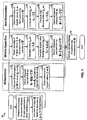
FIG. 3 shows an embodiment of aframe structure 300 that may be used for a TDD MIMO-OFDM system. Data transmission occurs in units of TDD frames, with each TDD frame covering a particular time duration (e.g., 2 msec). Each TDD frame is partitioned into a downlink phase and an uplink phase. The downlink phase is further partitioned into multiple segments for multiple downlink transport channels. In the embodiment shown inFIG. 3 , the downlink transport channels include a broadcast channel (BCH), a forward control channel (FCCH), and a forward channel (FCH). Similarly, the uplink phase is partitioned into multiple segments for multiple uplink transport channels. In the embodiment shown inFIG. 3 , the uplink transport channels include a reverse channel (RCH) and a random access channel (RANCH). - In the downlink phase, a
BCH segment 310 is used to transmit one BCH protocol data unit (PDU) 312, which includes abeacon pilot 314, aMIMO pilot 316, and aBCH message 318. The beacon pilot is transmitted from all access point antennas and is used by the user terminals for timing and frequency acquisition. The MIMO pilot is transmitted from all access point antennas with different orthogonal codes and is used by the user terminals for channel estimation. The BCH message carries system parameters for the user terminals in the system. AnFCCH segment 320 is used to transmit one FCCH PDU, which carries assignments for downlink and uplink resources and other signaling for the user terminals. AnFCH segment 330 is used to transmit one or more FCH PDUs 332. Different types of FCH PDU may be defined. For example, anFCH PDU 332a includes only adata packet 336a, and anFCH PDU 332b includes a downlink steeredreference 334b and adata packet 336b. - In the uplink phase, an
RCH segment 340 is used to transmit one or more RCH PDUs 342 on the uplink. Different types of RCH PDU may also be defined. For example, anRCH PDU 342a includes an uplink steeredreference 344a and adata packet 346a. AnRACH segment 350 is used by the user terminals to gain access to the system and to send short messages on the uplink. AnRACH PDU 352 may be sent withinRACH segment 350 and includes an uplink steeredreference 354 and amessage 356. - For the embodiment shown in
FIG. 3 , the beacon and MIMO pilots are sent on the downlink in the BCH segment in each TDD frame. A steered reference may or may not be sent in any given FCH/RCH PDU. A steered reference may also be sent in an RACH PDU to allow the access point to estimate pertinent vectors during system access. - For simplicity, the following description is for a communication between one access point and one user terminal. The MIMO pilot is transmitted by the access point and used by the user terminal to obtain an estimate of the calibrated downlink channel response, Ĥ cdn (k), for k ∈ K . The calibrated uplink channel response may then be estimated as


- Û sp(k) is an ( N ap × Nap ) unitary matrix of left eigenvectors of Ĥ cup(k),
- Σ̂(k) is an (Nap × Nut ) diagonal matrix of singular values of Ĥ cup(k); and
- V̂ ut(k) is an (Nut × Nut) unitary matrix of right eigenvectors of Ĥ cup(k),
- Similarly, the singular value decomposition of the estimated calibrated downlink channel response matrix, Ĥ cup(k), may be expressed as:

- As shown in equations (32) and (33), the matrices of left and right eigenvectors for one link are the complex conjugate of the matrices of right and left eigenvectors, respectively, for the other link. For simplicity, reference to the matrices Û ap(k) and V̂ ut(k) in the following description may also refer to their various other forms (e.g., V̂ ut(k) may refer to V̂ ut(k), V̂ ut(k),


- The singular value decomposition may be performed independently for the channel response matrix Ĥ cup(k) for each of the usable subbands to determine the Ns eigenmodes for the subband. The singular value estimates for each diagonal matrix Σ̂(k) may be ordered such that {σ̂1(k)≥σ̂2(k)≥...≥σ̂N
s (k)}, where σ̂1(k) is the largest singular value estimate and σ̂Ns (k) is the smallest singular value estimate for subband k. When the singular value estimates for each diagonal matrix Σ̂(k) are ordered, the eigenvectors (or columns) of the associated matrices Û (k) and V̂ (k) are also ordered correspondingly. After the ordering, σ̂1(k) represents the singular value estimate for the best eigenmode for subband k, which is also often referred to as the "principal" eigenmode. - A "wideband" eigenmode may be defined as the set of same-order eigenmodes of all subbands after the ordering. Thus, the m-th wideband eigenmode includes the m-th eigenmodes of all subbands. Each wideband eigenmode is associated with a respective set of eigenvectors for all of the subbands. The "principal" wideband eigenmode is the one associated with the largest singular value estimate in the matrix Σ̂(k) for each of the subbands.
- The user terminal can transmit a steered reference on the uplink. The uplink steered reference for the m-th wideband eigenmode may be expressed as:

m . (k)] ; and p(k) is the pilot symbol for the k-th subband. - The received uplink steered reference at the access point may be expressed as:

- û ap,m (k) is the m-th column of the matrix Û ap(k) for the k-th subband, with Û ap(k) = [ û ap,1(k) û ap,2(k) ... û ap,N
ap (k)]; and - σ̂ m (k) is the singular value estimate for the k-th subband of the m-th wideband eigenmode.
- The access point can obtain an initial matched filter matrix M̂ ap(k), for k ∈ K, based on the uplink steered reference, as described above. The access point may thereafter obtain an enhanced orthogonal matched filter matrix M̃ ap(k), for k ∈ K, based on M̂ ap(k) and using any one of the orthogonalization techniques described above.
- Using QR factorization, the matrix M̃ ap(k) may be obtained as:


where - Q ap(k) is a unitary matrix that is the ortho-normal basis for M̃ ap(k);
- R̃ ap(k) is a diagonal matrix derived based on M̂ ap(k); and
- Σ̃ ap(k)= R̃ ap(k) and Ũ ap(k)= Q ap(k).
- Using mean square error computation, the matrix M̃ ap(k) may be obtained as:


Σ̃ ap(k) is the diagonal matrix whose elements are the 2-norm of the columns of

- Using polar decomposition, the matrix M̃ ap(k) may be obtained as:


- The matrix M̃ ap(k) may be used by the access point for matched filtering of uplink data transmission from the user terminal, as described below.
- The spatial processing performed by the user terminal to transmit data on multiple eigenmodes on the uplink may be expressed as:

- The received uplink data transmission at the access point may be expressed as:

- The matched filtering by the access point may be expressed as:

- Σ̂(k) = diag (σ̃1,1(k) (σ̃2,2(k) σ̃ N
T ,NT (k)); and -

- For the TDD MIMO system, the access point may also use the matrices Ũ ap(k), for k ∈ K, for spatial processing for data transmission on the downlink to the user terminal. The spatial processing performed by the access point to transmit data on multiple eigenmodes on the downlink may be expressed as:

- The received downlink data transmission at the user terminal may be expressed as:

where r dn(k) is the receive vector for the downlink data transmission for the k-th subband. - The matched filtering by the user terminal may be expressed as:

where -

- Σ̂(k)=diag (σ̂1,1(k) (σ̂2,2(k) ... (σ̂ N
s ,Ns (k)) ; and -

- Table 1 summarizes the spatial processing at the access point and user terminal for both data transmission and reception on multiple wideband eigenmodes.
Table 1 Downlink Uplink Access Point Transmit: Receive : 

User Terminal Receive : Transmit: 

- It can be shown that the use of the matrices Û ap(k), for k ∈ K, (with orthogonalized columns) for spatial processing for downlink data transmission can provide substantial improvement over the use of matrices Û ap(k), for k ∈ K, (with unorthogonalized columns) obtained from the initial matched filter matrices M̂ (k), for k ∈ K.
-
FIG. 4 shows transmission of steered reference and data on the downlink and uplink for an exemplary transmission scheme. The MIMO pilot is transmitted on the downlink by the access point in each TDD frame (block 412). The user terminal receives and processes the downlink MEMO pilot to obtain an estimate the downlink channel response Ĥ cdn(k), for k ∈ K. The user terminal then estimates the uplink channel response as
- The user terminal then transmits the uplink steered reference on the RACH or the RCH using the matrices V̂ m(k), for k ∈ K, as shown in equation (34) and
FIG. 3 , during system access (step 422). The columns of V̂ m (k) are also referred to as steering vectors when used for data transmission. The access point receives and processes the uplink steered reference on the RACH or the RCH to obtain the matrices Σ̃(k) and Û ap(k), for k ∈ K, as described above (step 424). The columns of Û ap(k) are eigenvectors that may be used for both data reception as well as data transmission. The user terminal may thereafter transmit the uplink steered reference and data on the RCH using the matrices V̂ m(k), for k ∈ K , as shown in equation (41) andFIG. 3 (step 432). The access point receives and processes the uplink steered reference on the RCH to update the matrices Σ̃(k) and Ũ ap(k), for k ∈ K (step 434). The access point also performs matched filtering for the received uplink data transmission using the matrices Σ̃(k) and Ũ ap(k) (also step 434). - The access point may thereafter transmit an optional downlink steered reference and data on the FCH using the matrices Ũ ap(k) for k ∈ K , as shown in equation (44) and
FIG. 3 (step 442). If a downlink steered reference is transmitted, then the user terminal can process the downlink steered reference to update the matrices Σ̂(k) and V̂ m(k), for k ∈ K (step 444) and may also perform orthogonalization to ensure that the columns of V̂ m(k) are orthogonal. The user terminal also performs matched filtering for the received downlink data transmission using the matrices Σ̂(k) and V̂ m(k) (also step 444). - The pilot and data transmission scheme shown in
FIG. 4 provides several advantages. First, the MIMO pilot transmitted by the access point may be used by multiple user terminals in the system to estimate the response of their respective MIMO channels. Second, the computation for the singular value decomposition of Ĥ cup (k), for k ∈ K , is distributed among the user terminals (i.e., each user terminal performs singular value decomposition of its own set of estimated channel response matrices for the usable subbands). Third, the access point can obtain the matrices Σ̃(k) and Ũ ap(k), for k ∈ K , which are used for uplink and downlink spatial processing, based on the steered reference without having to estimate the MIMO channel response. - Various other transmission schemes may also be implemented for MIMO and MIMO-OFDM systems, and this is within the scope of the invention. For example, the MIMO pilot may be transmitted by the user terminal and the steered reference may be transmitted by the access point.
-
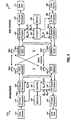
FIG. 5 shows a block diagram of an embodiment of anaccess point 210x and auser terminal 220x in MIMO-OFDM system 200. For clarity, in this embodiment,access point 210x is equipped with four antennas that can be used for data transmission and reception, anduser terminal 220x is also equipped with four antennas for data transmission/reception. In general, the access point and user terminal may each be equipped with any number of transmit antennas and any number of receive antennas. - On the downlink, at
access point 210x, a transmit (TX)data processor 514 receives traffic data from adata source 512 and signaling and other data from a controller 530.TX data processor 514 formats, codes, interleaves, and modulates the data to provide modulation symbols, which are also referred to as data symbols. A TXspatial processor 520 then receives and multiplexes the data symbols with pilot symbols, performs the required spatial processing with the matrices
modulators 522a through 522d are then transmitted fromantennas 524a through 524d, respectively. - At
user terminal 220x, fourantennas 552a through 552d receive the transmitted downlink modulated signals, and each antenna provides a received signal to a respective demodulator (DEMOD) 554. Eachdemodulator 554 performs processing complementary to that performed bymodulator 522 and provides received symbols. A receive (RX)spatial processor 560 then performs matched filtering on the received symbols from alldemodulators 554a through 554d to provide recovered data symbols, which are estimates of the data symbols transmitted by the access point. AnRX data processor 570 further processes (e.g., symbol demaps, deinterleaves, and decodes) the recovered data symbols to provide decoded data, which may be provided to adata sink 572 for storage and/or acontroller 580 for further processing. - RX
spatial processor 560 also processes the received pilot symbols to obtain an estimate of the downlink channel response, Ĥ cdn(k), for k ∈K . Controller 580 may then decompose each matrix Ĥ cdn(k) to obtain Σ̂(k) and V̂ m(k).Controller 580 may further derive (1) the downlink matched filter matrices M̂ m(k), for k ∈ K , based on Σ̂(k) and V̂ m(k), and (2) the scaling matrices G m(k), for k ∈ K , based on Σ̂(k).Controller 580 may then provide M̂ m(k) toRX data processor 560 for downlink matched filtering and V̂ m(k) to a TXspatial processor 590. - The processing for the uplink may be the same or different from the processing for the downlink. Data and signaling are processed (e.g., coded, interleaved, and modulated) by a
TX data processor 588, multiplexed with pilot symbols, and further spatially processed by TXspatial processor 590 with the matrices V̂ m(k), for k ∈ K . The transmit symbols from TXspatial processor 590 are further processed bymodulators 554a through 554d to generate four uplink modulated signals, which are then transmitted viaantennas 552a through 552d. - At access point 510, the uplink modulated signals are received by
antennas 524a through 524d and demodulated bydemodulators 522a through 522d to provide received symbols for the uplink steered reference and data transmission. An RXspatial processor 540 then processes the received uplink steered reference to obtain estimates of u m σ m , for k ∈ K and m ∈ {1 ... NS }, which are provided to controller 530. Controller then obtains M̂ ap(k) and Σ̃(k) based on the estimates of u m σ m , performs orthogonalization of M̂ ap(k) to obtain M̃ ap(k) and Ũ ap(k), and derives G ap(k) based on Σ̃(k).Controller 580 then provides M̃ ap(k) and G ap(k) to RXspatial processor 540 for uplink matched filtering and
spatial processor 520 for downlink spatial processing. - RX
spatial processor 540 performs matched filtering of the received uplink data transmission with M̃ ap(k) and G ap(k) to provide recovered data symbols, which are further processed by anRX data processor 542 to provide decoded data. The decoded data may be provided to adata sink 544 for storage and/or controller 530 for further processing. - Controller 530 performs the processing to obtain the matched filter matrices M̃ ap(k) and the scaling matrices G ap(k), for k ∈ K, for uplink data transmission and the matrices

Controller 580 performs the processing to obtain the matched filter matrices M̂ m(k) and the scaling matrices G m (k), for k ∈ K , for downlink data transmission and the matrices V̂ m(k), for k ∈ K , for uplink data transmission.Controllers 530 and 580 further control the operation of various processing units at the access point and user terminal, respectively.Memory units controllers 530 and 580, respectively. -
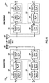
FIG. 6 shows a block diagram of the spatial processing performed byaccess point 210x anduser terminal 220x to transmit data on multiple eigenmodes on the downlink and uplink. - On the downlink, within TX
spatial processor 520 ataccess point 210x, the data vector s dn(k) for each subband k is first multiplied with the matrix
unit 610 and further multiplied with the correction matrix K̂ ap(k) by aunit 612 to obtain the transmit vector x dn(k) for subband k. The columns of the matrix
chain 614 withinmodulator 522 and transmitted over the MIMO channel touser terminal 220x.Unit 610 performs the spatial processing for downlink data transmission. - At
user terminal 220x, the downlink modulated signals are processed by a receivechain 654 withindemodulator 554 to obtain the receive vectors r dn (k) , for k ∈ K. Within RXspatial processor 560, the receive vector r dn(k) for each subband k is first multiplied with the matched filter matrix M̂ ut(k) by aunit 656 and further multiplied with the scaling matrix G m(k) by aunit 658 to obtain the vector ŝ dn(k), which is an estimate of the data vector s dn(k) transmitted for subband k.Units - On the uplink, within TX
spatial processor 590 atuser terminal 220x, the data vector s up(k) for each subband k is first multiplied with the matrix V̂ m(k) by aunit 660 and then further multiplied with the correction matrix K̂ ut(k) by aunit 662 to obtain the transmit vector x up(k) for subband k. The transmit vectors x up(k), for k ∈ K, are then processed by a transmitchain 664 withinmodulator 554 and transmitted over the MIMO channel to accesspoint 210x.Unit 660 performs the spatial processing for uplink data transmission. - At
access point 210x, the uplink modulated signals are processed by a receivechain 624 withindemodulator 522 to obtain the receive vectors r up(k), for k ∈ K. Within RXspatial processor 540, the receive vector r up(k) for each subband k is first multiplied with the matched filter matrix M̃ ap(k) by aunit 626 and further multiplied by the scaling matrix G ap(k) by aunit 628 to obtain the vector ŝ up(k) , which is an estimate of the data vector s up(k) transmitted for subband k.Units - The techniques described herein to derive eigenvectors for spatial processing may be implemented by various means. For example, these techniques may be implemented in hardware, software, or a combination thereof. For a hardware implementation, the elements used for these techniques may be implemented within one or more application specific integrated circuits (ASICs), digital signal processors (DSPs), digital signal processing devices (DSPDs), programmable logic devices (PLDs), field programmable gate arrays (FPGAs), processors, controllers, microcontrollers, microprocessors, other electronic units designed to perform the functions described herein, or a combination thereof.
- For a software implementation, the techniques may be implemented with modules (e.g., procedures, functions, and so on) that perform the functions described herein. The software codes may be stormed in a memory unit (e.g.,
memory units FIG. 5 ) and executed by a processor (e.g., controllers 530 and 580). The memory unit may be implemented within the processor for external to the processor, in which case it can be communicatively coupled to the processor via various means as is known in the art. - Headings are included herein for reference and to aid in locating certain sections. These headings are not intended to limit the scope of the concepts described therein under, and these concepts may have applicability in other sections throughout the entire specification.
- The previous description of the disclosed embodiments is provided to enable any person skilled in the art to make or use the present invention. Various modifications to these embodiments will be readily apparent to those skilled in the art, and the generic principles defined herein may be applied to other embodiments without departing from the scope of the invention. Thus, the present invention is not intended to be limited to the embodiments shown herein but is to be accorded the widest scope consistent with the claims.
Claims (37)
- An apparatus for use in a wireless multiple-input multiple-output, MIMO, communications system (200), comprising:means (522a - 522d) for obtaining a plurality of sets of received symbols, one set for each of a plurality of steered references received via a first link and generated based on a plurality of steering vectors, a steered reference being one of a plurality of scaled steering vectors, and a steering vector being one of a plurality of right eigenvectors of an RxT channel response matrix of the first link having M eigenmodes, with R being the number of receive antennas and T being the number of transmit antennas; andmeans (530, 580) for deriving a matched filter based on a plurality of M sets of receive symbols, wherein the matched filter includes a plurality of right eigenvectors corresponding to the plurality of steering vectors.
- The apparatus of claim 1, wherein the plurality of eigenvectors of the matched filter are orthogonal to one another.
- The apparatus of claim 2, wherein the plurality of eigenvectors of the matched filter are orthogonalized using QR factorization.
- The apparatus of claim 3, further comprising:means (580) for estimating gains associated with the plurality of steering vectors based on the plurality of sets of received symbols; andmeans (580) for ordering the plurality of eigenvectors based on the estimated gains.
- The apparatus of claim 2, wherein the plurality of eigenvectors of the matched filter are orthogonalized using minimum square error computation.
- The apparatus of claim 2, wherein the plurality of eigenvectors of the matched filter are orthogonalized using polar decomposition.
- The apparatus of claim 1, wherein the plurality of steered references is received over multiple frames.
- The apparatus of claim 1, further comprising:means (540) for performing matched filtering of a data transmission received via the first link using the matched filter.
- The apparatus of claim 1, wherein the means for deriving the matched filter further comprises:means (530) for determining a plurality of scaled vectors based on the plurality of sets of received symbols, wherein each of the plurality of scaled vectors corresponds to a respective one of the plurality of steering vectors; andmeans (530) for deriving a plurality of eigenvectors based on the plurality of scaled vectors, wherein the plurality of eigenvectors are used in the matched filter for matched filtering of data transmission received via the first link.
- The apparatus of claim 9, wherein each of the plurality of scaled vectors is determined based on at least one set of received symbols for at least one steered reference symbol generated based on the corresponding steering vector.
- The apparatus of claim 9, wherein the plurality of eigenvectors are orthogonal to one another.
- The apparatus of claim 11, wherein the means for deriving includes means (530, 580) for performing QR factorization on the plurality of scaled vectors to obtain the plurality of eigenvectors.
- The apparatus of claim 11, wherein the means for deriving includes means (530, 580) for performing polar decomposition on the plurality of scaled vectors to obtain the plurality of eigenvectors.
- The apparatus of claim 11, wherein the means for deriving includes means (530, 580) for performing minimum square error computation on the plurality of scaled vectors to obtain the plurality of eigenvectors.
- The apparatus of claim 11, further comprising:means (530, 580) for estimating singular values based on the plurality of scaled vectors; andmeans (530, 580) for deriving a matched filter for the first link based on the plurality of eigenvectors and the estimated singular values.
- The apparatus of claim 11, wherein the plurality of eigenvectors are used for spatial processing for data transmission on a second link.
- The apparatus of claim 16, wherein the first link is an uplink and the second link is a downlink in the MIMO communication system.
- The apparatus of claim 11, wherein the MIMO communication system utilizes orthogonal frequency division multiplexing (OFDM), and wherein the plurality of eigenvectors are derived for each of a plurality of subbands.
- A method for use in a wireless multiple-input multiple-output, MIMO, communications system comprising:obtaining (112, 114) a plurality of sets of received symbols, one set for each of a plurality of steered references received via a first link and generated based on a plurality of steering vectors, a steered reference being one of a plurality of scaled steering vectors, and a steering vector being one of a plurality of right eigenvectors of an RxT channel response matrix of the first link having M eigenmodes, with R being the number of receive antennas and T being the number of transmit antennas; andderiving (116, 138, 148) a matched filter based on a plurality of M sets of received symbols, wherein the matched filter includes a plurality of right eigenvectors corresponding to the plurality of steering vectors.
- The method of claim 19, wherein the plurality of eigenvectors of the matched filter are orthogonal to one another.
- The method of claim 20, wherein the plurality of eigenvectors of the matched filter are orthogonalized using QR factorization (124).
- The method of claim 21, further comprising:estimating gains associated with the plurality of steering vectors based on the plurality of sets of received symbols; andordering the plurality of eigenvectors based on the estimated gains.
- The method of claim 20, wherein the plurality of eigenvectors of the matched filter are orthogonalized using minimum square error computation (138).
- The method of claim 20, wherein the plurality of eigenvectors of the matched filter are orthogonalized using polar decomposition (148).
- The method of claim 19, wherein the plurality of steered references is received over multiple frames (300).
- The method of claim 19, further comprising:performing (150) matched filtering of a data transmission received via the first link using the matched filter.
- The method of claim 19, wherein the step of deriving the matched filter further comprises:determining a plurality of scaled vectors based on the plurality of sets of received symbols, wherein each of the plurality of scaled vectors corresponds to a respective one of the plurality of steering vectors; andderiving a plurality of eigenvectors based on the plurality of scaled vectors, wherein the plurality of eigenvectors are used in the matched filter for matched filtering of data transmission received via the first link.
- The method of claim 27, wherein each of the plurality of scaled vectors is determined based on at least one set of received symbols for at least one steered reference symbol generated based on the corresponding steering vector.
- The method of claim 27, wherein the plurality of eigenvectors are orthogonal to one another.
- The method of claim 29, wherein the step of deriving includes
performing (124) QR factorization on the plurality of scaled vectors to obtain the plurality of eigenvectors. - The method of claim 29, wherein the step of deriving includes performing (144) polar decomposition on the plurality of scaled vectors to obtain the plurality of eigenvectors.
- The method of claim 29, wherein the step of deriving includes performing (138) minimum square error computation on the plurality of scaled vectors to obtain the plurality of eigenvectors.
- The method of claim 29, further comprising:estimating singular values based on the plurality of scaled vectors; andderiving a matched filter for the first link based on the plurality of eigenvectors and the estimated singular values.
- The method of claim 29, wherein the plurality of eigenvectors are used for spatial processing for data transmission on a second link.
- The method of claim 34, wherein the first link is an uplink and the second link is a downlink in the MIMO communication system (200).
- The method of claim 29, wherein the MIMO communication system utilizes orthogonal frequency division multiplexing (OFDM), and wherein the plurality of eigenvectors are derived for each of a plurality of subbands.
- A computer-program product for use in a wireless multiple-input multiple-output, MIMO, communications system comprising a computer readable medium having instructions thereon, the instructions comprising code for carrying out the method of any of claims 19 to 36.
Applications Claiming Priority (3)
| Application Number | Priority Date | Filing Date | Title |
|---|---|---|---|
| US43276002P | 2002-12-11 | 2002-12-11 | |
| US10/729,070 US7280625B2 (en) | 2002-12-11 | 2003-12-04 | Derivation of eigenvectors for spatial processing in MIMO communication systems |
| EP03796943A EP1570616B1 (en) | 2002-12-11 | 2003-12-09 | Derivation of eigenvectors for spatial processing in mimo communication systems |
Related Parent Applications (2)
| Application Number | Title | Priority Date | Filing Date |
|---|---|---|---|
| EP03796943A Division EP1570616B1 (en) | 2002-12-11 | 2003-12-09 | Derivation of eigenvectors for spatial processing in mimo communication systems |
| EP03796943.3 Division | 2003-12-09 |
Publications (2)
| Publication Number | Publication Date |
|---|---|
| EP1940098A1 EP1940098A1 (en) | 2008-07-02 |
| EP1940098B1 true EP1940098B1 (en) | 2010-08-25 |
Family
ID=32511664
Family Applications (2)
| Application Number | Title | Priority Date | Filing Date |
|---|---|---|---|
| EP08006516A Expired - Lifetime EP1940098B1 (en) | 2002-12-11 | 2003-12-09 | Derivation of eigenvectors for spatial processing in MIMO communication systems |
| EP03796943A Expired - Lifetime EP1570616B1 (en) | 2002-12-11 | 2003-12-09 | Derivation of eigenvectors for spatial processing in mimo communication systems |
Family Applications After (1)
| Application Number | Title | Priority Date | Filing Date |
|---|---|---|---|
| EP03796943A Expired - Lifetime EP1570616B1 (en) | 2002-12-11 | 2003-12-09 | Derivation of eigenvectors for spatial processing in mimo communication systems |
Country Status (16)
| Country | Link |
|---|---|
| US (2) | US7280625B2 (en) |
| EP (2) | EP1940098B1 (en) |
| JP (2) | JP4532412B2 (en) |
| KR (1) | KR101000170B1 (en) |
| CN (2) | CN101615983B (en) |
| AT (2) | ATE479263T1 (en) |
| AU (2) | AU2003297873C1 (en) |
| BR (1) | BR0317173A (en) |
| CA (3) | CA2809768C (en) |
| DE (2) | DE60322424D1 (en) |
| ES (2) | ES2349490T3 (en) |
| HK (1) | HK1088143A1 (en) |
| IL (1) | IL168932A (en) |
| MX (1) | MXPA05006231A (en) |
| RU (1) | RU2337493C2 (en) |
| WO (1) | WO2004054191A1 (en) |
Families Citing this family (80)
| Publication number | Priority date | Publication date | Assignee | Title |
|---|---|---|---|---|
| US8194770B2 (en) | 2002-08-27 | 2012-06-05 | Qualcomm Incorporated | Coded MIMO systems with selective channel inversion applied per eigenmode |
| US8170513B2 (en) | 2002-10-25 | 2012-05-01 | Qualcomm Incorporated | Data detection and demodulation for wireless communication systems |
| US8570988B2 (en) | 2002-10-25 | 2013-10-29 | Qualcomm Incorporated | Channel calibration for a time division duplexed communication system |
| US7324429B2 (en) | 2002-10-25 | 2008-01-29 | Qualcomm, Incorporated | Multi-mode terminal in a wireless MIMO system |
| US8169944B2 (en) | 2002-10-25 | 2012-05-01 | Qualcomm Incorporated | Random access for wireless multiple-access communication systems |
| US7986742B2 (en) | 2002-10-25 | 2011-07-26 | Qualcomm Incorporated | Pilots for MIMO communication system |
| US8134976B2 (en) | 2002-10-25 | 2012-03-13 | Qualcomm Incorporated | Channel calibration for a time division duplexed communication system |
| US20040081131A1 (en) | 2002-10-25 | 2004-04-29 | Walton Jay Rod | OFDM communication system with multiple OFDM symbol sizes |
| US8320301B2 (en) | 2002-10-25 | 2012-11-27 | Qualcomm Incorporated | MIMO WLAN system |
| US8208364B2 (en) | 2002-10-25 | 2012-06-26 | Qualcomm Incorporated | MIMO system with multiple spatial multiplexing modes |
| US8218609B2 (en) | 2002-10-25 | 2012-07-10 | Qualcomm Incorporated | Closed-loop rate control for a multi-channel communication system |
| US7002900B2 (en) | 2002-10-25 | 2006-02-21 | Qualcomm Incorporated | Transmit diversity processing for a multi-antenna communication system |
| US7151809B2 (en) * | 2002-10-25 | 2006-12-19 | Qualcomm, Incorporated | Channel estimation and spatial processing for TDD MIMO systems |
| US7280625B2 (en) | 2002-12-11 | 2007-10-09 | Qualcomm Incorporated | Derivation of eigenvectors for spatial processing in MIMO communication systems |
| US7680461B2 (en) | 2003-11-05 | 2010-03-16 | Sony Corporation | Wireless communications system, wireless communications method, and wireless communications apparatus |
| US7298805B2 (en) * | 2003-11-21 | 2007-11-20 | Qualcomm Incorporated | Multi-antenna transmission for spatial division multiple access |
| US9473269B2 (en) | 2003-12-01 | 2016-10-18 | Qualcomm Incorporated | Method and apparatus for providing an efficient control channel structure in a wireless communication system |
| US8204149B2 (en) | 2003-12-17 | 2012-06-19 | Qualcomm Incorporated | Spatial spreading in a multi-antenna communication system |
| US7336746B2 (en) | 2004-12-09 | 2008-02-26 | Qualcomm Incorporated | Data transmission with spatial spreading in a MIMO communication system |
| WO2005081439A1 (en) | 2004-02-13 | 2005-09-01 | Neocific, Inc. | Methods and apparatus for multi-carrier communication systems with adaptive transmission and feedback |
| US8169889B2 (en) | 2004-02-18 | 2012-05-01 | Qualcomm Incorporated | Transmit diversity and spatial spreading for an OFDM-based multi-antenna communication system |
| US7492741B2 (en) * | 2004-04-12 | 2009-02-17 | Alcatel-Lucent Usa Inc. | Space-time multipath searcher |
| US7346115B2 (en) * | 2004-04-22 | 2008-03-18 | Qualcomm Incorporated | Iterative eigenvector computation for a MIMO communication system |
| US8923785B2 (en) | 2004-05-07 | 2014-12-30 | Qualcomm Incorporated | Continuous beamforming for a MIMO-OFDM system |
| US8285226B2 (en) | 2004-05-07 | 2012-10-09 | Qualcomm Incorporated | Steering diversity for an OFDM-based multi-antenna communication system |
| KR101098215B1 (en) * | 2004-05-10 | 2011-12-28 | 소니 주식회사 | System, method, and apparatus for wireless communication, and recording medium |
| US7616695B1 (en) * | 2004-06-17 | 2009-11-10 | Marvell International Ltd. | MIMO equalizer design: an algorithmic perspective |
| US7978649B2 (en) | 2004-07-15 | 2011-07-12 | Qualcomm, Incorporated | Unified MIMO transmission and reception |
| MX2007001710A (en) | 2004-08-11 | 2007-04-16 | Interdigital Tech Corp | Channel sounding for improved system performance. |
| JP4754906B2 (en) * | 2004-08-31 | 2011-08-24 | 株式会社エヌ・ティ・ティ・ドコモ | Communication system, communication node, and communication method |
| US7366245B2 (en) * | 2004-09-10 | 2008-04-29 | Intel Corporation | Calibration in MIMO systems |
| CN100388645C (en) * | 2004-09-28 | 2008-05-14 | 上海贝尔阿尔卡特股份有限公司 | Pre-coding method and device for improving V-BLAST detection performance |
| US8064503B2 (en) * | 2004-09-28 | 2011-11-22 | Panasonic Corporation | Multicarrier communication apparatus and multicarrier communication method |
| CN100373811C (en) * | 2004-12-10 | 2008-03-05 | 电子科技大学 | Method for signal testing of distributed type multiinput-multioutput system |
| US7719993B2 (en) * | 2004-12-30 | 2010-05-18 | Intel Corporation | Downlink transmit beamforming |
| US7778826B2 (en) * | 2005-01-13 | 2010-08-17 | Intel Corporation | Beamforming codebook generation system and associated methods |
| US7554952B2 (en) * | 2005-02-09 | 2009-06-30 | Alcatel-Lucent Usa Inc. | Distributed multiple antenna scheduling for wireless packet data communication system using OFDM |
| US7747271B2 (en) * | 2005-03-02 | 2010-06-29 | Qualcomm Incorporated | Radiated power control for a multi-antenna transmission |
| JP4646680B2 (en) * | 2005-03-04 | 2011-03-09 | 三洋電機株式会社 | Calibration method and radio apparatus and communication system using the same |
| US8515359B2 (en) * | 2005-03-09 | 2013-08-20 | Intel Corporation | Method and apparatus to provide low cost transmit beamforming for network devices |
| US7978759B1 (en) * | 2005-03-24 | 2011-07-12 | Marvell International Ltd. | Scalable equalizer for multiple-in-multiple-out (MIMO) wireless transmission |
| US7602855B2 (en) * | 2005-04-01 | 2009-10-13 | Interdigital Technology Corporation | Method and apparatus for singular value decomposition of a channel matrix |
| JP4646682B2 (en) * | 2005-04-13 | 2011-03-09 | 三洋電機株式会社 | Calibration method and radio apparatus and communication system using the same |
| US7466749B2 (en) | 2005-05-12 | 2008-12-16 | Qualcomm Incorporated | Rate selection with margin sharing |
| US8358714B2 (en) | 2005-06-16 | 2013-01-22 | Qualcomm Incorporated | Coding and modulation for multiple data streams in a communication system |
| WO2007012053A1 (en) * | 2005-07-20 | 2007-01-25 | Stmicroelectronics, S.R.L. | Apparatus and method for detecting communications from multiple sources |
| US9025689B2 (en) | 2005-07-20 | 2015-05-05 | Stmicroelectronics S.R.L. | Method and apparatus for multiple antenna communications, and related systems and computer program |
| CA2515997A1 (en) * | 2005-08-15 | 2007-02-15 | Research In Motion Limited | Implementation of joint space-time optimum filters (jstof) using qr and eigenvalue decompositions |
| EP1929691B1 (en) * | 2005-09-30 | 2012-03-14 | Huawei Technologies Co., Ltd. | Resource allocation method for MIMO-OFDM of multi-user access systems |
| US8200164B2 (en) | 2005-12-01 | 2012-06-12 | Intel Corporation | Wireless communication system, associated methods and data structures |
| US8543070B2 (en) | 2006-04-24 | 2013-09-24 | Qualcomm Incorporated | Reduced complexity beam-steered MIMO OFDM system |
| US8494084B1 (en) | 2006-05-02 | 2013-07-23 | Marvell International Ltd. | Reuse of a matrix equalizer for the purpose of transmit beamforming in a wireless MIMO communication system |
| US8290089B2 (en) * | 2006-05-22 | 2012-10-16 | Qualcomm Incorporated | Derivation and feedback of transmit steering matrix |
| US7864657B2 (en) * | 2006-05-23 | 2011-01-04 | Motorola Mobility, Inc. | Method and apparatus for performing stream weighting in an SDMA communication system |
| JP4836186B2 (en) * | 2006-05-31 | 2011-12-14 | 三洋電機株式会社 | Transmitter |
| KR100789754B1 (en) * | 2006-07-28 | 2008-01-02 | 한국전자통신연구원 | Method of maximum likelihood detection using lattice reduction in multi-input multi-output system |
| KR101210332B1 (en) * | 2006-09-27 | 2012-12-10 | 삼성전자주식회사 | Apparatus for controlling power of relay in amplify-forward relay system and method using the same |
| EP1912367B1 (en) * | 2006-10-11 | 2010-12-15 | Thomson Licensing | Method of decoding of a received multidimensional signal and corresponding device |
| US8885744B2 (en) | 2006-11-10 | 2014-11-11 | Qualcomm Incorporated | Providing antenna diversity in a wireless communication system |
| EP1936851B1 (en) * | 2006-12-18 | 2019-08-28 | Huawei Technologies Co., Ltd. | Method and apparatus for transmitting/receiving data and control information through an uplink in a wireless communication system |
| EP2119155A2 (en) | 2007-03-14 | 2009-11-18 | STMicroelectronics S.r.l. | A method and apparatus for multiple antenna communications, computer program product therefor |
| US7809074B2 (en) * | 2007-03-16 | 2010-10-05 | Freescale Semiconductor, Inc. | Generalized reference signaling scheme for multi-user, multiple input, multiple output (MU-MIMO) using arbitrarily precoded reference signals |
| US8223872B1 (en) | 2007-04-04 | 2012-07-17 | Marvell International Ltd. | Reuse of a matrix equalizer for the purpose of transmit beamforming in a wireless MIMO communication system |
| US8199841B1 (en) | 2007-04-26 | 2012-06-12 | Marvell International Ltd. | Channel tracking in a wireless multiple-input multiple-output (MIMO) communication system |
| GB2449935A (en) * | 2007-06-08 | 2008-12-10 | Fujitsu Ltd | Closed loop MIMO communication system using SISO r.m.s. delay spread to estimate eigen coherence bandwidth. |
| TWI400902B (en) * | 2007-06-28 | 2013-07-01 | Ind Tech Res Inst | Method and apparatus for demapping symbol in multi-input multi-output communication system |
| US8379745B1 (en) * | 2007-07-06 | 2013-02-19 | Marvell International Ltd. | Forward channel variation detection in a wireless communication system |
| KR100959645B1 (en) * | 2007-10-31 | 2010-05-26 | 한국전자통신연구원 | Method for transmission and reception in mu-mimo system |
| WO2009057876A1 (en) * | 2007-10-31 | 2009-05-07 | Electronics And Telecommunications Research Institute | Transmitting/receiving method for multi-user multiple-input multiple-output system |
| JP5122428B2 (en) * | 2008-02-04 | 2013-01-16 | 株式会社エヌ・ティ・ティ・ドコモ | Mobile communication system, receiving apparatus and method |
| US8340605B2 (en) * | 2008-08-06 | 2012-12-25 | Qualcomm Incorporated | Coordinated transmissions between cells of a base station in a wireless communications system |
| CN101686500B (en) * | 2008-09-25 | 2013-01-23 | 中国移动通信集团公司 | Method and user terminal for determining correlation parameters, and signal forming method and base station |
| EP2374099A1 (en) * | 2008-12-30 | 2011-10-12 | Telecom Italia S.p.A. | Method and system of content recommendation |
| EP2491689A1 (en) * | 2009-10-20 | 2012-08-29 | Telefonaktiebolaget LM Ericsson (publ) | Controllable filter to diagonalize a transmission channel |
| US8750400B2 (en) * | 2010-01-04 | 2014-06-10 | Broadcom Corporation | Method and system for an iterative multiple user multiple input multiple output (MU-MIMO) communication system |
| JP2013176008A (en) * | 2012-02-27 | 2013-09-05 | Kyocera Corp | Communication system, base station, mobile station, and communication control method |
| FR3009913B1 (en) * | 2013-08-23 | 2015-08-28 | Thales Sa | METHOD FOR DETECTING AN ELECTROMAGNETIC SIGNAL BY A DIAGRAM DIVERSITY ANTENNA ARRAY AND DEVICE USING THE METHOD |
| WO2018187902A1 (en) | 2017-04-10 | 2018-10-18 | Qualcomm Incorporated | An efficient interleaver design for polar codes |
| CN109461295B (en) * | 2018-12-07 | 2021-06-11 | 连尚(新昌)网络科技有限公司 | Household alarm method and equipment |
| US10826649B1 (en) | 2018-12-19 | 2020-11-03 | Marvell Asia Pte, Ltd. | WiFi receiver architecture |
Family Cites Families (7)
| Publication number | Priority date | Publication date | Assignee | Title |
|---|---|---|---|---|
| US6058105A (en) * | 1997-09-26 | 2000-05-02 | Lucent Technologies Inc. | Multiple antenna communication system and method thereof |
| US6952454B1 (en) * | 2000-03-22 | 2005-10-04 | Qualcomm, Incorporated | Multiplexing of real time services and non-real time services for OFDM systems |
| US20020154705A1 (en) * | 2000-03-22 | 2002-10-24 | Walton Jay R. | High efficiency high performance communications system employing multi-carrier modulation |
| US6961388B2 (en) * | 2001-02-01 | 2005-11-01 | Qualcomm, Incorporated | Coding scheme for a wireless communication system |
| DE10162548A1 (en) | 2001-12-19 | 2003-07-17 | Siemens Ag | Combination of adaptive modulation and space frequency block coding or antenna weighting for efficient encoded data transmission |
| US7039001B2 (en) * | 2002-10-29 | 2006-05-02 | Qualcomm, Incorporated | Channel estimation for OFDM communication systems |
| US7280625B2 (en) | 2002-12-11 | 2007-10-09 | Qualcomm Incorporated | Derivation of eigenvectors for spatial processing in MIMO communication systems |
-
2003
- 2003-12-04 US US10/729,070 patent/US7280625B2/en active Active
- 2003-12-09 MX MXPA05006231A patent/MXPA05006231A/en active IP Right Grant
- 2003-12-09 CA CA2809768A patent/CA2809768C/en not_active Expired - Lifetime
- 2003-12-09 ES ES08006516T patent/ES2349490T3/en not_active Expired - Lifetime
- 2003-12-09 CN CN2009101601762A patent/CN101615983B/en not_active Expired - Lifetime
- 2003-12-09 EP EP08006516A patent/EP1940098B1/en not_active Expired - Lifetime
- 2003-12-09 DE DE60322424T patent/DE60322424D1/en not_active Expired - Lifetime
- 2003-12-09 CN CNB2003801086298A patent/CN100542145C/en not_active Expired - Lifetime
- 2003-12-09 ES ES03796943T patent/ES2308027T3/en not_active Expired - Lifetime
- 2003-12-09 EP EP03796943A patent/EP1570616B1/en not_active Expired - Lifetime
- 2003-12-09 RU RU2005121540/09A patent/RU2337493C2/en active
- 2003-12-09 JP JP2005511766A patent/JP4532412B2/en not_active Expired - Lifetime
- 2003-12-09 AT AT08006516T patent/ATE479263T1/en not_active IP Right Cessation
- 2003-12-09 AU AU2003297873A patent/AU2003297873C1/en not_active Ceased
- 2003-12-09 CA CA2809754A patent/CA2809754C/en not_active Expired - Lifetime
- 2003-12-09 DE DE60333961T patent/DE60333961D1/en not_active Expired - Lifetime
- 2003-12-09 KR KR1020057010650A patent/KR101000170B1/en active IP Right Grant
- 2003-12-09 BR BR0317173-6A patent/BR0317173A/en active Search and Examination
- 2003-12-09 AT AT03796943T patent/ATE402551T1/en not_active IP Right Cessation
- 2003-12-09 WO PCT/US2003/039392 patent/WO2004054191A1/en active Application Filing
- 2003-12-09 CA CA2509196A patent/CA2509196C/en not_active Expired - Lifetime
-
2005
- 2005-06-01 IL IL168932A patent/IL168932A/en not_active IP Right Cessation
-
2006
- 2006-07-21 HK HK06108138.0A patent/HK1088143A1/en not_active IP Right Cessation
-
2007
- 2007-09-04 US US11/849,976 patent/US7551698B2/en not_active Expired - Lifetime
-
2009
- 2009-09-24 AU AU2009220023A patent/AU2009220023C1/en not_active Ceased
-
2010
- 2010-04-08 JP JP2010089246A patent/JP5175315B2/en not_active Expired - Lifetime
Also Published As
Similar Documents
| Publication | Publication Date | Title |
|---|---|---|
| EP1940098B1 (en) | Derivation of eigenvectors for spatial processing in MIMO communication systems | |
| US7151809B2 (en) | Channel estimation and spatial processing for TDD MIMO systems | |
| US9967005B2 (en) | Pilots for MIMO communication systems | |
| US7346115B2 (en) | Iterative eigenvector computation for a MIMO communication system | |
| EP1880484B1 (en) | Rate selection for eigensteering in a mimo communication system | |
| JP2006504336A (en) | Channel calibration for time division duplex communication systems. |
Legal Events
| Date | Code | Title | Description |
|---|---|---|---|
| PUAI | Public reference made under article 153(3) epc to a published international application that has entered the european phase |
Free format text: ORIGINAL CODE: 0009012 |
|
| 17P | Request for examination filed |
Effective date: 20080331 |
|
| AC | Divisional application: reference to earlier application |
Ref document number: 1570616 Country of ref document: EP Kind code of ref document: P |
|
| AK | Designated contracting states |
Kind code of ref document: A1 Designated state(s): AT BE BG CH CY CZ DE DK EE ES FI FR GB GR HU IE IT LI LU MC NL PT RO SE SI SK TR |
|
| RIN1 | Information on inventor provided before grant (corrected) |
Inventor name: KETCHUM, JOHN W. Inventor name: WALLACE, MARK S.C/O QUALCOMM INCORPORATED Inventor name: GAAL, PETER |
|
| 17Q | First examination report despatched |
Effective date: 20081217 |
|
| AKX | Designation fees paid |
Designated state(s): AT BE BG CH CY CZ DE DK EE ES FI FR GB GR HU IE IT LI LU MC NL PT RO SE SI SK TR |
|
| GRAP | Despatch of communication of intention to grant a patent |
Free format text: ORIGINAL CODE: EPIDOSNIGR1 |
|
| RTI1 | Title (correction) |
Free format text: DERIVATION OF EIGENVECTORS FOR SPATIAL PROCESSING IN MIMO COMMUNICATION SYSTEMS |
|
| GRAS | Grant fee paid |
Free format text: ORIGINAL CODE: EPIDOSNIGR3 |
|
| GRAA | (expected) grant |
Free format text: ORIGINAL CODE: 0009210 |
|
| AC | Divisional application: reference to earlier application |
Ref document number: 1570616 Country of ref document: EP Kind code of ref document: P |
|
| AK | Designated contracting states |
Kind code of ref document: B1 Designated state(s): AT BE BG CH CY CZ DE DK EE ES FI FR GB GR HU IE IT LI LU MC NL PT RO SE SI SK TR |
|
| REG | Reference to a national code |
Ref country code: GB Ref legal event code: FG4D |
|
| REG | Reference to a national code |
Ref country code: CH Ref legal event code: EP |
|
| REG | Reference to a national code |
Ref country code: IE Ref legal event code: FG4D |
|
| REF | Corresponds to: |
Ref document number: 60333961 Country of ref document: DE Date of ref document: 20101007 Kind code of ref document: P |
|
| REG | Reference to a national code |
Ref country code: RO Ref legal event code: EPE |
|
| REG | Reference to a national code |
Ref country code: SE Ref legal event code: TRGR |
|
| REG | Reference to a national code |
Ref country code: NL Ref legal event code: T3 |
|
| REG | Reference to a national code |
Ref country code: ES Ref legal event code: FG2A Effective date: 20101221 |
|
| PG25 | Lapsed in a contracting state [announced via postgrant information from national office to epo] |
Ref country code: AT Free format text: LAPSE BECAUSE OF FAILURE TO SUBMIT A TRANSLATION OF THE DESCRIPTION OR TO PAY THE FEE WITHIN THE PRESCRIBED TIME-LIMIT Effective date: 20100825 |
|
| PGFP | Annual fee paid to national office [announced via postgrant information from national office to epo] |
Ref country code: IE Payment date: 20101006 Year of fee payment: 8 |
|
| PG25 | Lapsed in a contracting state [announced via postgrant information from national office to epo] |
Ref country code: PT Free format text: LAPSE BECAUSE OF FAILURE TO SUBMIT A TRANSLATION OF THE DESCRIPTION OR TO PAY THE FEE WITHIN THE PRESCRIBED TIME-LIMIT Effective date: 20101227 Ref country code: SI Free format text: LAPSE BECAUSE OF FAILURE TO SUBMIT A TRANSLATION OF THE DESCRIPTION OR TO PAY THE FEE WITHIN THE PRESCRIBED TIME-LIMIT Effective date: 20100825 Ref country code: CY Free format text: LAPSE BECAUSE OF FAILURE TO SUBMIT A TRANSLATION OF THE DESCRIPTION OR TO PAY THE FEE WITHIN THE PRESCRIBED TIME-LIMIT Effective date: 20100825 |
|
| PGFP | Annual fee paid to national office [announced via postgrant information from national office to epo] |
Ref country code: BG Payment date: 20101102 Year of fee payment: 8 Ref country code: CZ Payment date: 20101008 Year of fee payment: 8 Ref country code: FI Payment date: 20101213 Year of fee payment: 8 Ref country code: HU Payment date: 20101029 Year of fee payment: 8 Ref country code: RO Payment date: 20101206 Year of fee payment: 8 |
|
| REG | Reference to a national code |
Ref country code: HU Ref legal event code: AG4A Ref document number: E009345 Country of ref document: HU |
|
| PG25 | Lapsed in a contracting state [announced via postgrant information from national office to epo] |
Ref country code: GR Free format text: LAPSE BECAUSE OF FAILURE TO SUBMIT A TRANSLATION OF THE DESCRIPTION OR TO PAY THE FEE WITHIN THE PRESCRIBED TIME-LIMIT Effective date: 20101126 |
|
| PGFP | Annual fee paid to national office [announced via postgrant information from national office to epo] |
Ref country code: BE Payment date: 20101105 Year of fee payment: 8 Ref country code: SE Payment date: 20101027 Year of fee payment: 8 Ref country code: NL Payment date: 20101230 Year of fee payment: 8 |
|
| PG25 | Lapsed in a contracting state [announced via postgrant information from national office to epo] |
Ref country code: DK Free format text: LAPSE BECAUSE OF FAILURE TO SUBMIT A TRANSLATION OF THE DESCRIPTION OR TO PAY THE FEE WITHIN THE PRESCRIBED TIME-LIMIT Effective date: 20100825 |
|
| PG25 | Lapsed in a contracting state [announced via postgrant information from national office to epo] |
Ref country code: EE Free format text: LAPSE BECAUSE OF FAILURE TO SUBMIT A TRANSLATION OF THE DESCRIPTION OR TO PAY THE FEE WITHIN THE PRESCRIBED TIME-LIMIT Effective date: 20100825 Ref country code: SK Free format text: LAPSE BECAUSE OF FAILURE TO SUBMIT A TRANSLATION OF THE DESCRIPTION OR TO PAY THE FEE WITHIN THE PRESCRIBED TIME-LIMIT Effective date: 20100825 |
|
| PLBE | No opposition filed within time limit |
Free format text: ORIGINAL CODE: 0009261 |
|
| STAA | Information on the status of an ep patent application or granted ep patent |
Free format text: STATUS: NO OPPOSITION FILED WITHIN TIME LIMIT |
|
| PG25 | Lapsed in a contracting state [announced via postgrant information from national office to epo] |
Ref country code: MC Free format text: LAPSE BECAUSE OF NON-PAYMENT OF DUE FEES Effective date: 20101231 |
|
| REG | Reference to a national code |
Ref country code: CH Ref legal event code: PL |
|
| 26N | No opposition filed |
Effective date: 20110526 |
|
| REG | Reference to a national code |
Ref country code: DE Ref legal event code: R097 Ref document number: 60333961 Country of ref document: DE Effective date: 20110526 |
|
| PG25 | Lapsed in a contracting state [announced via postgrant information from national office to epo] |
Ref country code: LI Free format text: LAPSE BECAUSE OF NON-PAYMENT OF DUE FEES Effective date: 20101231 Ref country code: CH Free format text: LAPSE BECAUSE OF NON-PAYMENT OF DUE FEES Effective date: 20101231 |
|
| BERE | Be: lapsed |
Owner name: QUALCOMM INC. Effective date: 20111231 |
|
| REG | Reference to a national code |
Ref country code: NL Ref legal event code: V1 Effective date: 20120701 |
|
| PG25 | Lapsed in a contracting state [announced via postgrant information from national office to epo] |
Ref country code: CZ Free format text: LAPSE BECAUSE OF NON-PAYMENT OF DUE FEES Effective date: 20111209 |
|
| REG | Reference to a national code |
Ref country code: SE Ref legal event code: EUG |
|
| PG25 | Lapsed in a contracting state [announced via postgrant information from national office to epo] |
Ref country code: FI Free format text: LAPSE BECAUSE OF NON-PAYMENT OF DUE FEES Effective date: 20111209 |
|
| REG | Reference to a national code |
Ref country code: IE Ref legal event code: MM4A |
|
| PG25 | Lapsed in a contracting state [announced via postgrant information from national office to epo] |
Ref country code: LU Free format text: LAPSE BECAUSE OF NON-PAYMENT OF DUE FEES Effective date: 20101209 |
|
| PG25 | Lapsed in a contracting state [announced via postgrant information from national office to epo] |
Ref country code: IE Free format text: LAPSE BECAUSE OF NON-PAYMENT OF DUE FEES Effective date: 20111209 Ref country code: SE Free format text: LAPSE BECAUSE OF NON-PAYMENT OF DUE FEES Effective date: 20111210 Ref country code: BE Free format text: LAPSE BECAUSE OF NON-PAYMENT OF DUE FEES Effective date: 20111231 Ref country code: TR Free format text: LAPSE BECAUSE OF FAILURE TO SUBMIT A TRANSLATION OF THE DESCRIPTION OR TO PAY THE FEE WITHIN THE PRESCRIBED TIME-LIMIT Effective date: 20100825 Ref country code: RO Free format text: LAPSE BECAUSE OF NON-PAYMENT OF DUE FEES Effective date: 20111209 |
|
| PG25 | Lapsed in a contracting state [announced via postgrant information from national office to epo] |
Ref country code: HU Free format text: LAPSE BECAUSE OF NON-PAYMENT OF DUE FEES Effective date: 20111210 |
|
| PG25 | Lapsed in a contracting state [announced via postgrant information from national office to epo] |
Ref country code: NL Free format text: LAPSE BECAUSE OF NON-PAYMENT OF DUE FEES Effective date: 20120701 |
|
| PG25 | Lapsed in a contracting state [announced via postgrant information from national office to epo] |
Ref country code: BG Free format text: LAPSE BECAUSE OF NON-PAYMENT OF DUE FEES Effective date: 20121231 |
|
| REG | Reference to a national code |
Ref country code: FR Ref legal event code: PLFP Year of fee payment: 13 |
|
| REG | Reference to a national code |
Ref country code: FR Ref legal event code: PLFP Year of fee payment: 14 |
|
| REG | Reference to a national code |
Ref country code: FR Ref legal event code: PLFP Year of fee payment: 15 |
|
| PGFP | Annual fee paid to national office [announced via postgrant information from national office to epo] |
Ref country code: GB Payment date: 20221109 Year of fee payment: 20 Ref country code: FR Payment date: 20221110 Year of fee payment: 20 Ref country code: DE Payment date: 20220615 Year of fee payment: 20 |
|
| PGFP | Annual fee paid to national office [announced via postgrant information from national office to epo] |
Ref country code: ES Payment date: 20230109 Year of fee payment: 20 |
|
| PGFP | Annual fee paid to national office [announced via postgrant information from national office to epo] |
Ref country code: IT Payment date: 20221214 Year of fee payment: 20 |
|
| REG | Reference to a national code |
Ref country code: DE Ref legal event code: R071 Ref document number: 60333961 Country of ref document: DE |
|
| REG | Reference to a national code |
Ref country code: ES Ref legal event code: FD2A Effective date: 20231227 |
|
| REG | Reference to a national code |
Ref country code: GB Ref legal event code: PE20 Expiry date: 20231208 |
|
| PG25 | Lapsed in a contracting state [announced via postgrant information from national office to epo] |
Ref country code: GB Free format text: LAPSE BECAUSE OF EXPIRATION OF PROTECTION Effective date: 20231208 |
|
| PG25 | Lapsed in a contracting state [announced via postgrant information from national office to epo] |
Ref country code: ES Free format text: LAPSE BECAUSE OF EXPIRATION OF PROTECTION Effective date: 20231210 |
|
| PG25 | Lapsed in a contracting state [announced via postgrant information from national office to epo] |
Ref country code: GB Free format text: LAPSE BECAUSE OF EXPIRATION OF PROTECTION Effective date: 20231208 Ref country code: ES Free format text: LAPSE BECAUSE OF EXPIRATION OF PROTECTION Effective date: 20231210 |