EP1912367B1 - Method of decoding of a received multidimensional signal and corresponding device - Google Patents
Method of decoding of a received multidimensional signal and corresponding device Download PDFInfo
- Publication number
- EP1912367B1 EP1912367B1 EP06301038A EP06301038A EP1912367B1 EP 1912367 B1 EP1912367 B1 EP 1912367B1 EP 06301038 A EP06301038 A EP 06301038A EP 06301038 A EP06301038 A EP 06301038A EP 1912367 B1 EP1912367 B1 EP 1912367B1
- Authority
- EP
- European Patent Office
- Prior art keywords
- matrix
- decoding
- signal
- estimation
- transmitted signal
- Prior art date
- Legal status (The legal status is an assumption and is not a legal conclusion. Google has not performed a legal analysis and makes no representation as to the accuracy of the status listed.)
- Not-in-force
Links
Images


Classifications
-
- H—ELECTRICITY
- H04—ELECTRIC COMMUNICATION TECHNIQUE
- H04L—TRANSMISSION OF DIGITAL INFORMATION, e.g. TELEGRAPHIC COMMUNICATION
- H04L1/00—Arrangements for detecting or preventing errors in the information received
- H04L1/02—Arrangements for detecting or preventing errors in the information received by diversity reception
- H04L1/06—Arrangements for detecting or preventing errors in the information received by diversity reception using space diversity
- H04L1/0618—Space-time coding
- H04L1/0631—Receiver arrangements
-
- H—ELECTRICITY
- H04—ELECTRIC COMMUNICATION TECHNIQUE
- H04L—TRANSMISSION OF DIGITAL INFORMATION, e.g. TELEGRAPHIC COMMUNICATION
- H04L1/00—Arrangements for detecting or preventing errors in the information received
- H04L1/02—Arrangements for detecting or preventing errors in the information received by diversity reception
- H04L1/06—Arrangements for detecting or preventing errors in the information received by diversity reception using space diversity
- H04L1/0618—Space-time coding
- H04L1/0625—Transmitter arrangements
-
- H—ELECTRICITY
- H04—ELECTRIC COMMUNICATION TECHNIQUE
- H04L—TRANSMISSION OF DIGITAL INFORMATION, e.g. TELEGRAPHIC COMMUNICATION
- H04L1/00—Arrangements for detecting or preventing errors in the information received
- H04L1/02—Arrangements for detecting or preventing errors in the information received by diversity reception
- H04L1/06—Arrangements for detecting or preventing errors in the information received by diversity reception using space diversity
- H04L1/0618—Space-time coding
- H04L1/0637—Properties of the code
- H04L1/0668—Orthogonal systems, e.g. using Alamouti codes
-
- H—ELECTRICITY
- H04—ELECTRIC COMMUNICATION TECHNIQUE
- H04L—TRANSMISSION OF DIGITAL INFORMATION, e.g. TELEGRAPHIC COMMUNICATION
- H04L27/00—Modulated-carrier systems
- H04L27/26—Systems using multi-frequency codes
- H04L27/2601—Multicarrier modulation systems
- H04L27/2647—Arrangements specific to the receiver only
- H04L27/2649—Demodulators
Definitions
- the present invention relates to the field of digital communication. More specifically, it deals with an efficient way to implement a decoding based on a lattice, that is used, for example, in a decoding of a signal transmitted through a noisy channel or multi-user detection.
- An optimal decoder is the one that finds the candidate digital signal that is the most likely, given the received observed signal. Such optimal decoder is said to be optimal in the sense of Maximum Likelihood (or ML).
- a basic approach to perform ML decoding consists in exhaustively enumerating all possible transmitted digital signals and selecting the most likely candidate.
- the selection criterion often consists in computing a Euclidean distance between the filtered candidate and the received observation.
- exhaustive enumeration is very time consuming and most of the time impractical for real time applications. Indeed the number of candidates, and hence the decoder complexity, is exponential with respect to the length of the digital signal. For instance a signal carrying 10 bits may take 1024 (or 2 10 ) different values and all these values need being enumerated in basic ML decoding.
- lattice decoders More appropriate ML decoding algorithms have emerged based on a multidimensional lattice description of the problem, which will be referred to as lattice decoders in the sequel. For instance a signal made of 8 consecutive 16QAM symbols can be described by a 8 dimension lattice with 16 discrete possible values per dimension. After linear filtering, the lattice will remain a lattice but it will be distorted. Instead of enumerating all possible lattice points (16 8 in the present case), lattice decoders will restrict to evaluating lattice points that are in the vicinity of the received signal.
- FR 2 863 422 A published on June 10, 2005 discloses a transmission method in a MIMO communication system implementing a linear pre-coding of the signal to be transmitted.
- the invention is aimed at alleviating these drawbacks of the prior art.
- the objective of the invention is to simplify the implementation of a decoding method based on a lattice, while keeping good performances.
- the invention proposes a method of decoding of a multidimensional received signal corresponding to a discrete multidimensional coded signal transmitted through a channel, so-called transmitted signal, characterized in that it comprises the following steps:
- a permutated transmitted signal is a discrete multidimensional coded signal, the components of which are permuted.
- Lattice decoding corresponds to a decoding of a distorted discrete multidimensional signal.
- Sorting of vectors of the first matrix can be considered as sorting of columns and/or sorting of rows of the first matrix, depending whether column or row notation is used.
- the method according to claim 1 characterized in that the first matrix is an equivalent channel matrix equal to a product of a channel matrix by a code matrix.
- the matrix derived from the reordered matrix is the reordered matrix and in that it comprises a QR preprocessing step, the decoding step comprising a decomposition of the reordered matrix.
- the first matrix is a Gram matrix that is equal to the product of the transpose of an equivalent channel matrix by the equivalent channel matrix, the equivalent channel matrix being equal to a product of a channel matrix by a code matrix, the reordered matrix being obtained by sorting of columns and rows of the first matrix according to a decreasing colinearity criterion.
- the method comprises a Cholesky preprocessing step, the decoding step comprising a Cholesky decomposition of the reordered matrix.
- the sorting of vectors of the first matrix according to a decreasing colinearity criterion comprise at least a scalar product computation between two vectors of the first matrix.
- the scalar product can be made on real field or on complex field.
- the scalar product can be normalized or not.
- the discrete multidimensional coded signal comprises data representative of a digital video broadcast signal.
- the inventions also concerns a device of decoding of a multidimensional received signal corresponding to a discrete multidimensional coded signal transmitted through a channel, so-called transmitted signal, characterized in that it comprises the following means:
- This device is for example a receiver, a corresponding chip, a terminal (such as a mobile device, a telecommunication device).
- the invention reduces the complexity of lattice based decoders.
- some types of wireless channels strongly distort the lattice representing the transmitted signal, which induces a larger decoding complexity of lattice decoders (e.g. when the lattice basis is ill conditioned).
- This is the case for strongly spatially correlated channels and/or channels presenting a strong LOS (Line Of Sight) component.
- the invention brings a significant complexity reduction for this type of wireless channels, which has been observed as being a critical channel type that conditions the lattice decoder complexity and dimension the receiver design.
- the invention can be applied to all systems that are based on lattice decoding, especially to decoding of data transmitted through a MIMO channel or to multi-user detection.
- Figure 1 represents a wireless network 1 comprising several stations 10 to 12. Each station 10 to 12 comprises a transmitter and a receiver using a MIMO (or Multiple Input Multiple Output) antenna system. Station 10 communicates with stations 11 and 12 through a wireless link.
- MIMO Multiple Input Multiple Output
- Figure 2 represents an exemplary architecture of a data transmitter 2 capable of sending data in a way compliant with the invention applied to decoding of a signal transmitted through a MIMO noisy channel.
- the data transmitter 2 can be implemented in stations 10 to 12.
- the transmitter 2 comprises:
- the transmitter 2 receives a binary signal 22 which is digitally modulated by the modulator 21 with a first modulation which is, for instance a QAM modulation (or "Quadrature Amplitude Modulation") (e.g. 16 QAM or 64QAM).
- the modulator 21 generates groups of Q complex QAM symbols S1 to SQ. Q is for example equal to 8.
- the STBC is, for instance, a Golden code such as disclosed in document " The Golden Code: A 2 x 2 Full-Rate Space-Time Code with Non-Vanishing Determinants," which has been written by J.-C. Belfiore, G. Rekaya, E. Viterbo (and published in IEEE Transactions on Information Theory, vol. 51, n. 4, pp. 1432-1436, Apr. 2005 .).
- the STBC is as disclosed in " Space-Time block codes from orthogonal designs" document written by V.Tarokh, H. Jafarkhani, and R. A. Calderbank (and published in IEEE Transactions on Information Theory, vol. 45, pp. 1456-1467, July 1999 ).
- the STBC is based on a complex matrix of dimension N tx *N where N is the time dimension of the STBC.
- the generated STBC 24 is mapped in the time/frequency mapper that transmits a dedicated signal 261 to 26Ntx to each of OFDM modulator 271 to 27Ntx. Then, each modulator 271 to 27Ntx modulates its input signal into an OFDM modulated signal that is sent on an antenna respectively 281 to 28Ntx (after possibly filtering, frequency transposition and amplification as usually done in a radio transmitted signal). As summary, the STBC codeword 24 is then sent on a MIMO channel.
- Such a transmitter system is disclosed in " Space-frequency coded broadband OFDM systems", written by H. Bölcskei and A. J. Paulraj (and published in Proc. Wireless Commun. Networking Conf., Chicago, IL, Sept. 23-28, 2000, pp. 1-6 ).
- a single carrier modulation can replace the OFDM modulation (or any multi carrier modulation such IOTA (for "Isotropic Orthogonal Transform Algorithm")). Then, a time/frequency mapper 25 and the OFDM modulators 271 to 27Ntx are replaced by at least two single carrier modulators associated each with a antenna.
- IOTA Independent Orthogonal Transform Algorithm
- the first modulation can be of any digital modulation, e.g. nPSK (for “Phase Shift Keying with n phase values) or nQAM (eg with n equals to 16, 32, 64, 256).
- nPSK Phase Shift Keying with n phase values
- nQAM e.g with n equals to 16, 32, 64, 256.
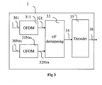
- Figure 3 represents an exemplary architecture of a data receiver 3 according to a specific embodiment of the invention.
- the receiver 3 receives a signal send by the transmitter 2 through a wireless channel.
- This channel is noisy and comprise Additive White Gaussian Noise (or AWGN) and possibly other noise such as interferences.
- the sent signal can also be affected by multipath echos and/or Doppler effect.
- the data receiver 3 can be implemented in stations 10 to 12.
- the receiver 3 comprises:
- the receiver 3 matches the transmitter 2 (especially for modulation and code used by the transmitter). Then, according to variants using single carrier modulation inside the transmitter, the OFDM demodulators are replaced by the corresponding single carrier demodulators.
- the receiver 3 comprises Nrx receive antennas 301 to 30 Nrx so that the received signal 301 to 30 Nrx can be represented by a Nrx*N matrix, or equivalently a ( Nrx*N)* 1 vector R.
- N is, for instance, equal to 2 and represents the time and/or frequency range occupied by the STBC.
- the space/time coding process takes place with real inputs (instead of complex inputs). Then, the C matrix is a real matrix with a dimension (2 Ntx*N) *(2 Q) .
- ⁇ 2 represents the variance of the resulting whitened noise.
- the time/frequency demapper 33 receives demodulated signal from OFDM demodulators 311 to 31 Nrx and is doing the reverse mapping (corresponding to dual operation of mapper 25). It provides a demapped signal to decoder 35.
- the decoder 35 is a lattice decoder and is particularly well suited to perform ML decoding of the Space-Time Block encoded signal.
- the decoder 35 is exploiting the properties of the noise distribution by selecting points in a lattice that are between two spheres around a received point, the decoded point being chosen among selected points.
- This enables a reduction of the decoder complexity as the number of selected points can be lowered in comparison with a state of art decoder where the selected points are within one sphere around the received point.
- it is unlikely that ML decoding would choose points of the lattice that are too close to the received point as decoded points. Then, the decoder does not select these points as potential candidates for decoded points. Reduction of number of selected points enables a dramatic reduction of decoding complexity (the decoding complexity depend of the level of noise and is increasing with the number of selected points).
- FIG 7 represents the distribution of received data received by the receiver 3.
- Figure 7 gives a simplified lattice representation 7 of the decoding problem. The problem is illustrated in the case where the dimension K is 2 (Q equals 1) for the sake of illustration clarity. Those two dimensions are represented respectively by lines 77 and lines 78. Intersections of lines 77 and 78 corresponds to points of the lattice 7.
- the transmitted signal (which is the ML point here), is a lattice point 750 represented by US' 0 .
- the lattice points that can be considered as candidates for ML decoding are, according to the invention, in a search space between two spheres 71 and 72:
- a lattice point 74 is within the sphere 71 and is not among candidate points for the ML decoding according to the invention (whereas this point would have been selected by a state of the art decoding method).
- Lattice points 760 to 764 are outside the sphere 72 and are not among candidate points for the ML decoding.
- Lattice points 750 to 754 are in sphere 72 and outside sphere 71; then, these points are considered as candidates by the decoder.
- the horizontal axis 83 represents the normalized distance to the received point.
- the vertical axis 82 corresponds to the distribution of samples for a given normalized distance.
- the distances dmin and dmax are defined such that Pr( ⁇ > dmax ) equals 10 -2 and Pr( ⁇ ⁇ dmin ) equals 10 -2 . These probabilities are example values. It can be noted that area 801 corresponding to normalized distance lower than dmin and area 802 corresponding to normalized distance higher than dmax are very small (each having a normalized surface of 10 -2 ) compared to the middle area 800, where the normalized distance is greater than dmin and lower than dmax . On the given example, dmin is around 0.025 that is significant. Then, it shows that it is very unlikely that the distance between a point corresponding to the coded point (without noise) and the actual received point is below dmin.
- dmax gives an initial value for the radius of the sphere S(Rp,r) within which the search will take place.
- the probability that the transmitted signal is outside this sphere is 10 -2 . Setting the initial radius to dmax therefore allows reducing the initial search space, and hence the decoding complexity, for a given level of performance.
- dmin is introduced and can advantageously be used in the decoding process according to two ways, as follows:
- the integrated function is the probability density function (or pdf) of ⁇ 2
- p 0 is the desired probability threshold of the event (i.e. the transmitted signal is in S( R p, dmin )).
- dmin / ⁇ can be determined according to a predefined value of po.
- dmin can be determined by using approximations of above equation (e.g. by using a first or second orders of a Taylor series).
- Figure 4 represents an exemplary architecture of the decoder 35 of the receiver 3.
- Decoder 35 comprises following elements that are linked together by a data and address bus 44:
- the word « register » used in the specification can correspond to area of small capacity (some bits) or to very large area (e.g. a whole program or large amount of received or decoded data).
- ROM 42 comprises a program 420.
- Algorithm of the method according to the invention are stored in the ROM 42.
- the CPU 41 uploads the program 420 in the RAM and executes the corresponding instructions.
- RAM 43 comprises:
- the decoder 35 is implemented in pure hardware configuration (e.g. in one or several FPGA, ASIC or VLSI with corresponding memory) or in a configuration using both VLSI and DSP.
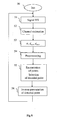
- Figure 5 represents a decoding method implemented in the decoder 35.
- the decoding begins with a initialization step 50, wherein different parameters of the method are set to their initial value(s).
- the decoder 35 waits for and receives a signal from demapper 33.
- the CPU 41 makes a channel estimation 52 based upon the received signal (associated to one transmitted block) or part of it.
- the estimation 52 is based upon several received signals (or part of them), each being associated to a transmitted block.
- the estimation 52 is not done at each reception of signal corresponding to one transmitted block; in this case, it may be done when necessary according to the channel changes (e.g. every 1 ms).
- step 53 CPU 41 computes ⁇ using, for example, a pilot sequence and determines dmin as explained above and possibly dmax in a similar way.
- step 53 is executed after each channel estimation 52.
- step 53 is not done at each reception of signal corresponding to one transmitted block.
- CPU 41 is executing a preprocessing step 54.
- CPU 41 is enumerating lattice points and selects decoded point in a step 55.
- step 56 the components of the decoded point are inversely permutated according to the permutation produced by step 540.
- step 51 is reiterated.
- step 54 is performed by the DSP and step 55 by a VLSI (e.g. ASIC or FPGA).
- VLSI e.g. ASIC or FPGA
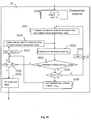
- FIG. 6 details preprocessing step 54. A brief explanation of the decoding method is first disclosed hereafter.
- CS in equation (1) denotes the STB (Space Time Block) encoded signal.
- the encoding process is represented by complex matrix multiplications in the present case but from a more general point of view, it shall be represented by real matrices where the real and imaginary parts of S are encoded separately.
- the STBC scheme disclosed in Alamouti document (“Space-Time block coding: A simple transmitter diversity technique for wireless communications”) can only be represented with such real notations.
- R R R I ⁇ R ⁇ H R - H I H I H R ⁇ C ⁇ ⁇ G ⁇ ⁇ S R S I ⁇ S ⁇ + v R v I ⁇ v ⁇
- C' is the STBC encoding matrix in real notations
- R and (.) / denote respectively the real and imaginary parts of a complex number or matrix.
- the dimension of the input signal S' which is the problem dimension
- K 2Q.
- lattice decoding algorithms more advantageously use a triangular matrix as a lattice basis, so that the starting point of the search algorithm is not (2) but it is given by equation (3):
- U is a upper triangular KxK matrix.
- U is the new lattice basis that is used by lattice decoding algorithms.
- the time/frequency dimension N is replaced by a time dimension if a single carrier modulation is used.
- the STBC decoder finds the best estimate of the transmitted signal S .
- the lattice decoders use a lattice representation of the problem, where each lattice point is a potential transmitted signal. From this lattice representation, they enumerate a reduced number of candidate signals with respect to what would do a basic ML decoder. For instance, with Q equals to 8 and using 16QAM constellation, a basic ML decoder will enumerate 16 8 candidates to decode a STBC codeword and the lattice decoders will only enumerate very few of them.
- the search space is reduced to the space between two spheres 71 and 72 of radius dmin and dmax .
- the decoding algorithm can be split into two main phases:
- the preprocessing phase 54 begins with a computation 540 of Gram Matrix.
- Gram matrix corresponds to a multiplication of an equivalent channel matrix new_G' by its transpose new_G' t .
- the received signal is projected on the matrix computed on step 541. This projection first multiplies the received signal R' by new_G' t and then by the inverse of U t .
- step 541 is replaced by a QR decomposition of a new equivalent channel matrix (new_G '), new_G ' being equal to QU where Q is an orthogonal matrix and U an upper triangular matrix.
- step 542 comprises a multiplication by Q t .
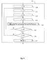
- Figure 12 represents details Gram Matrix computation 540.
- the step 540 begins with a step 5400 of computation of an equivalent channel matrix G' equal to the product HC .
- Step 540 consists in permuting the columns of the real matrix G' of equation (2) according to a particular criterion based on the components of the Gram matrix G' t G' .
- R R R I ⁇ R ⁇ H R - H I H I H R ⁇ C ⁇ ⁇ G ⁇ ⁇ S R S I ⁇ S ⁇ + v R v I ⁇ v ⁇
- the lattice basis is permuted so that successive dimensions that are addressed in the search phase are as collinear as possible.
- the component ( G' t G' ) ij contains the scalar product between i th and j th basis vectors that are respectively i th and j th column vectors of G', so that the larger abs(( G' t G' ) ij ), the more collinear the i th and j th vectors.
- complex notations are used (instead of real notation), the vectorial space on the field of real numbers is replaced by the vectorial space on the field of complex numbers and the scalar product (and associated norm) is changed accordingly.
- a matrix M is computed, M being equal to the product G' t G' plus ⁇ , where ⁇ is smaller than the smallest absolute value of M.
- ⁇ is smaller than the smallest absolute value of M.
- the use of ⁇ allows that the step 540 also produces a permutation of (1,.., K ) even when M is diagonal.
- the product G' t G' corresponds to computation of non normalized scalar products of vectors of G'.
- the diagonal of M is set to 0 ( M ( i,i ) equals 0 for every value of i from 1 to K ). This avoids producing the identity permutation or a permutation only based on the lattice basis vector norms, which performs worse than the present criterion.
- i_in a permutation vector
- the first dimension dealt with is the one corresponding to the smallest or largest diagonal value of G' t G' (this enables processing of the dimension with largest energy first, in the lattice decoding step).
- the vectors of M are sorted according to a decreasing colinearity criterion, vectors being compared 2 by 2 (that enables a dimension permutation).
- a counter i is set to 1.
- the element M ( i_in, P (1,1: i )) is set to 0.
- (1: i ) denotes the vector [1,2,...,i] so that P (1,1: i ) denotes the first i components of the row 1 of P.
- M ( i_in, P (1,1: i )) denotes the elements of row i_in of M having column indexes P (1,1: i ).
- This initialization 5404 of the i_in row of M is made to avoid producing twice the same index in the permutation vector (and hence not producing a permutation).
- a counter k is set to 1 and a variable max is set to 0.
- the CPU 41 checks if the absolute value of M ( i_in,k ) is superior or equal to max .
- max is set to the absolute value of M ( i_in,k ) and an index i_out is set to k.
- the index i_out corresponding to the basis vector is searched.
- the index i_out is the most collinear (i.e. largest absolute value of scalar product) with respect to the current basis vector i_in .
- the CPU 41 checks if the counter k is equal to K +1.
- step 5410 the value of P(1, i +1) is set to i_out . Adjacent dimensions in the permutation now have highest absolute value of scalar product. During, this step i_in is also set to i_out.
- the CPU 41 checks if i equals K.
- step 5404 is reiterated.
- This new matrices new_Gram and new_G' are the ones that will serve for the lattice decoding preprocessing phase (QR or Cholesky decomposition).
- step 541 is replaced by a QR decomposition of new_G', producing a new_Gram matrix is not necessary (during step 5413).
- M is equal to the product G ' t G and, it is checked whether M is diagonal or not. If so, steps 5402 to 5412 are replaced by a permutation that is only based on the diagonal values of M and more especially that comprises an ordering of its elements according to decreasing (or increasing) values of diagonal values.
- step 5401 can be replaced by step 13 disclosed in figure 13 .
- the scalar product between vectors of G' is normalized.
- Step 14 begins by a step 130 of set of a counter i to 0.
- a counter j is set to 0.
- the element M(i,j) is set to G' t G'(i,j) /sqrt( G' t G '(i,i)* G' t G '(j,j)), this scalar product being normalized.
- step 133 the CPU 41 checks if j equals K. If no, step 133 is reiterated.
- step 136 the CPU 41 checks if i equals K . If no, step 131 is reiterated. If yes, during a step 137, M is set to the sum M + ⁇ .
- Figure 9 and 10 detail decoding step 55, which comprises an enumeration of candidate lattice points that takes into account a minimum distance dmin.
- ML points are searched among lattice points (using the basis U) that are in a space between spheres 71 and 72 of radius respectively dmin and dmax .
- this search phase is implemented in different ways.
- Figures 9 and 10 detail two different embodiments.
- Other alternative search algorithms can be implemented according to the invention, these algorithm being based on algorithms such as so called tree search, branch and bound and wherein the ML points are searched in a space outside a sphere of a minimum radius dmin .
- Embodiment of figure 9 is based upon a sphere decoding (as the algorithm of Viterbo/Boutros) with a restriction of the selection lattice points that must not be too close to the received signal point (the distance between the selected points and the received signal point is greater than dmin ).
- dmin the distance between the selected points and the received signal point is greater than dmin .
- the ML point is in the largest sphere.
- This approach allows to define bounds for each component (or dimension) of the candidate signals S, within which discrete components of the signal are enumerated. That can be summarized by the equation: d min 2 ⁇ U - 1 ⁇ R p - S t ⁇ U t ⁇ U ⁇ U - 1 ⁇ R p - S ⁇ d max 2
- the components of S further satisfy the modulation constellation boundaries constraints as S components are a constellation point. For instance, if a 16QAM modulation is used, the components of S satisfy -3 ⁇ Si ⁇ 3.
- the step 55 begins with an initialization step 550 where a cumulated metric DDim associated to each dimension is set to 0, a maximum distance DMAX is set to infinity and a current dimension index Dim is set to K (lattice dimension).
Landscapes
- Engineering & Computer Science (AREA)
- Computer Networks & Wireless Communication (AREA)
- Signal Processing (AREA)
- Radio Transmission System (AREA)
- Compression, Expansion, Code Conversion, And Decoders (AREA)
- Reduction Or Emphasis Of Bandwidth Of Signals (AREA)
- Communication Control (AREA)
Abstract
Description
- The present invention relates to the field of digital communication. More specifically, it deals with an efficient way to implement a decoding based on a lattice, that is used, for example, in a decoding of a signal transmitted through a noisy channel or multi-user detection.
- Optimal decoding of digital signals that have been distorted by linear filtering (e.g. a wireless channel) and corrupted by noise is a key and recurrent issue in digital communications. An optimal decoder is the one that finds the candidate digital signal that is the most likely, given the received observed signal. Such optimal decoder is said to be optimal in the sense of Maximum Likelihood (or ML).
- A basic approach to perform ML decoding consists in exhaustively enumerating all possible transmitted digital signals and selecting the most likely candidate. The selection criterion often consists in computing a Euclidean distance between the filtered candidate and the received observation. However, such exhaustive enumeration is very time consuming and most of the time impractical for real time applications. Indeed the number of candidates, and hence the decoder complexity, is exponential with respect to the length of the digital signal. For instance a signal carrying 10 bits may take 1024 (or 210) different values and all these values need being enumerated in basic ML decoding.
- More appropriate ML decoding algorithms have emerged based on a multidimensional lattice description of the problem, which will be referred to as lattice decoders in the sequel. For instance a signal made of 8 consecutive 16QAM symbols can be described by a 8 dimension lattice with 16 discrete possible values per dimension. After linear filtering, the lattice will remain a lattice but it will be distorted. Instead of enumerating all possible lattice points (168 in the present case), lattice decoders will restrict to evaluating lattice points that are in the vicinity of the received signal.
- The main drawback of the state of the art is that lattice decoders are still complex (especially for real time applications) even if they have polynomial decoding complexity (instead of exponential for basic ML).
- Simplifications of lattice decoders for applications of MIMO (or Multiple Input Multiple Output) transmissions, have been suggested in the following documents:
- "VLSI implementation of MIMO detection using the sphere decoding algorithm" written by Burg & Al (and published in Solid-State Circuits, IEEE Journal of Volume 40, ); and
- "On maximum-likelihood detection and the search for the closest lattice point" written by Damen & Al (and published in Information Theory, IEEE Transactions on Volume 49, ).
- Indeed, the technique presented in these documents still remains complex.
-
FR 2 863 422 A - The invention is aimed at alleviating these drawbacks of the prior art.
- More particularly, the objective of the invention is to simplify the implementation of a decoding method based on a lattice, while keeping good performances.
- For this purpose, the invention proposes a method of decoding of a multidimensional received signal corresponding to a discrete multidimensional coded signal transmitted through a channel, so-called transmitted signal, characterized in that it comprises the following steps:
- computation of a first matrix with respect to an estimation of the channel and a code associated to the transmitted signal;
- sorting of the vectors of the first matrix according to a decreasing colinearity criteria, a permutation being applied to the vectors of the first matrix to obtain a reordered matrix;
- decoding of an observation with a lattice decoding by using the reordered matrix to get estimation of a permutated transmitted signal; and
- inverse permutation of the estimation of the permutated transmitted signal to get an estimation of the transmitted signal.
- According to the invention, a permutated transmitted signal is a discrete multidimensional coded signal, the components of which are permuted.
- Lattice decoding corresponds to a decoding of a distorted discrete multidimensional signal.
- Sorting of vectors of the first matrix can be considered as sorting of columns and/or sorting of rows of the first matrix, depending whether column or row notation is used.
- According to a specific feature, the method according to
claim 1, characterized in that the first matrix is an equivalent channel matrix equal to a product of a channel matrix by a code matrix. - According to an advantageous feature, the matrix derived from the reordered matrix is the reordered matrix and in that it comprises a QR preprocessing step, the decoding step comprising a decomposition of the reordered matrix.
- According to another advantageous feature, the first matrix is a Gram matrix that is equal to the product of the transpose of an equivalent channel matrix by the equivalent channel matrix, the equivalent channel matrix being equal to a product of a channel matrix by a code matrix, the reordered matrix being obtained by sorting of columns and rows of the first matrix according to a decreasing colinearity criterion.
- According to a specific feature, the method comprises a Cholesky preprocessing step, the decoding step comprising a Cholesky decomposition of the reordered matrix.
- Advantageously, the sorting of vectors of the first matrix according to a decreasing colinearity criterion comprise at least a scalar product computation between two vectors of the first matrix.
- The scalar product can be made on real field or on complex field.
- The scalar product can be normalized or not.
- According to a particular feature, the discrete multidimensional coded signal comprises data representative of a digital video broadcast signal.
- The inventions also concerns a device of decoding of a multidimensional received signal corresponding to a discrete multidimensional coded signal transmitted through a channel, so-called transmitted signal, characterized in that it comprises the following means:
- means of computation of a first matrix with respect to an estimation of the channel and a code associated to the transmitted signal;
- means of sorting of vectors of the first matrix according to a decreasing colinearity criterion, a permutation being applied to vectors of the first matrix to obtain a reordered matrix;
- means of decoding of an observation with a lattice decoding by using matrix derived from the reordered matrix to get estimation of a permutated transmitted signal; and
- means of inverse permutation of the estimation of the permutated transmitted signal to get an estimation of the transmitted signal.
- This device is for example a receiver, a corresponding chip, a terminal (such as a mobile device, a telecommunication device).
- The invention will be better understood, and other features and advantages will become apparent from reading the description that follows, the description referring to the appended drawings in which:
-
Figure 1 represents a wireless network; -
Figure 2 represents an exemplary architecture of a data transmitter capable of sending data in a way compliant with the invention; -
Figure 3 represents an exemplary architecture of a data receiver according to a specific embodiment of the invention; -
Figure 4 represents an exemplary architecture of a decoder inside the receiver offigure 3 ; -
Figure 5 represents a decoding method implemented in the receiver offigure 3 according to the invention; -
Figure 7 is a schematic view in a case the dimension of the decoding method ofFigure 5 is two; -
Figure 8 represents the distribution of the norm of the noise vector affecting the signal received by the receiver offigure 3 ; -
Figures 6 ;9 and10 represent detailed step of the decoding method ofFigure 5 ; -
Figure 11 represents a multi-user detection according to a specific embodiment of the invention; and -
Figures 12 and13 present matrix reordering step in the decoding method offigure 5 . - The invention reduces the complexity of lattice based decoders. In particular, it has been observed through simulations that some types of wireless channels strongly distort the lattice representing the transmitted signal, which induces a larger decoding complexity of lattice decoders (e.g. when the lattice basis is ill conditioned). This is the case for strongly spatially correlated channels and/or channels presenting a strong LOS (Line Of Sight) component. The invention brings a significant complexity reduction for this type of wireless channels, which has been observed as being a critical channel type that conditions the lattice decoder complexity and dimension the receiver design.
- The invention can be applied to all systems that are based on lattice decoding, especially to decoding of data transmitted through a MIMO channel or to multi-user detection.
- When applied to ML decoding of STBC encoded MIMO transmissions with large number of antennas (for example with at least four transmitting antennas), this allows reducing the lattice decoding complexity. As a consequence, this enables implementing high throughput high reliability wireless MIMO transmissions with reasonable receiver complexity.
-
Figure 1 represents awireless network 1 comprisingseveral stations 10 to 12. Eachstation 10 to 12 comprises a transmitter and a receiver using a MIMO (or Multiple Input Multiple Output) antenna system.Station 10 communicates withstations -
Figure 2 represents an exemplary architecture of adata transmitter 2 capable of sending data in a way compliant with the invention applied to decoding of a signal transmitted through a MIMO noisy channel. Thedata transmitter 2 can be implemented instations 10 to 12. - The
transmitter 2 comprises: - a
modulator 21; - an
encoder 23; - a time/
frequency mapper 25; -
Ntx OFDM modulators 271 to 27Ntx each modulating with an OFDM modulator aninput signal 261 to 26Ntx; and -
Ntx antennas 281 to 28Ntx, each being associated to an OFDM modulator respectively 271 to 27Ntx. - The
transmitter 2 receives abinary signal 22 which is digitally modulated by themodulator 21 with a first modulation which is, for instance a QAM modulation (or "Quadrature Amplitude Modulation") (e.g. 16 QAM or 64QAM). Themodulator 21 generates groups of Q complex QAM symbols S1 to SQ. Q is for example equal to 8. - Each group of
Q symbols 22 is then encoded with theencoder 23 to form a STBC (or Space Time Block Code)codeword 24. The STBC is, for instance, a Golden code such as disclosed in document "The Golden Code: A 2 x 2 Full-Rate Space-Time Code with Non-Vanishing Determinants," which has been written by J.-C. Belfiore, G. Rekaya, E. Viterbo (and published in IEEE Transactions on Information Theory, vol. 51, n. 4, pp. 1432-1436, Apr. 2005.). According to a variant, the STBC is as disclosed in "Space-Time block codes from orthogonal designs" document written by V.Tarokh, H. Jafarkhani, and R. A. Calderbank (and published in IEEE Transactions on Information Theory, vol. 45, pp. 1456-1467, July 1999). The STBC is based on a complex matrix of dimension Ntx*N where N is the time dimension of the STBC. - The generated
STBC 24 is mapped in the time/frequency mapper that transmits adedicated signal 261 to 26Ntx to each of OFDM modulator 271 to 27Ntx. Then, each modulator 271 to 27Ntx modulates its input signal into an OFDM modulated signal that is sent on an antenna respectively 281 to 28Ntx (after possibly filtering, frequency transposition and amplification as usually done in a radio transmitted signal). As summary, theSTBC codeword 24 is then sent on a MIMO channel. - Such a transmitter system is disclosed in "Space-frequency coded broadband OFDM systems", written by H. Bölcskei and A. J. Paulraj (and published in Proc. Wireless Commun. Networking Conf., Chicago, IL, Sept. 23-28, 2000, pp. 1-6).
- There are many possible variants of the transmitter that are compliant with the invention. Among them, a single carrier modulation can replace the OFDM modulation (or any multi carrier modulation such IOTA (for "Isotropic Orthogonal Transform Algorithm")). Then, a time/
frequency mapper 25 and theOFDM modulators 271 to 27Ntx are replaced by at least two single carrier modulators associated each with a antenna. Such a transmitter system is disclosed in "Space-Time block coding: A simple transmitter diversity technique for wireless communications" written by S. Alamouti (and published in IEEE Journal On Select Areas In Communications, vol. 16, pp. 1451-1458, October 1998). - According to other variants (that are compliant with previous ones), the first modulation can be of any digital modulation, e.g. nPSK (for "Phase Shift Keying with n phase values) or nQAM (eg with n equals to 16, 32, 64, 256...).
-
Figure 3 represents an exemplary architecture of adata receiver 3 according to a specific embodiment of the invention. Thereceiver 3 receives a signal send by thetransmitter 2 through a wireless channel. This channel is noisy and comprise Additive White Gaussian Noise (or AWGN) and possibly other noise such as interferences. The sent signal can also be affected by multipath echos and/or Doppler effect. Thedata receiver 3 can be implemented instations 10 to 12. - The
receiver 3 comprises: -
Nrx antennas 301 to 30Nrx; -
Nrx OFDM demodulators 311 to 31Nrx each demodulating a noisy OFDM modulated signal transmitted by an antenna respectively 301 to 30Nrx; - a time/
frequency demapper 33; and - a
decoder 35. - The
receiver 3 matches the transmitter 2 (especially for modulation and code used by the transmitter). Then, according to variants using single carrier modulation inside the transmitter, the OFDM demodulators are replaced by the corresponding single carrier demodulators. - The
receiver 3 comprises Nrx receiveantennas 301 to 30Nrx so that the receivedsignal 301 to 30Nrx can be represented by a Nrx*N matrix, or equivalently a (Nrx*N)*1 vector R. N is, for instance, equal to 2 and represents the time and/or frequency range occupied by the STBC. - The transmission between the
encoder 23 anddecoder 35 can be modeled by the following equation:
- Where the different parameters are as follows:
- R is the complex (Nrx*N)*1 received vector;
- H i is the complex Nrx*Ntx channel matrix at time/frequency interval i (frequency corresponds to a carrier of the multicarrier modulation; according to a variant using a single carrier modulation the interval i corresponds to a time interval);
- H=diag(H 1,..., H N ) is the complex block diagonal (N*Nrx)*(N*Ntx) channel matrix at time/
frequency intervals 1 to N; - C is the complex (Ntx*N)*Q STBC coding matrix, where Q is the number of input complex symbols per STBC codeword;
- S is the complex Q*1 input vector of discrete modulated symbols;
- ν is the complex (N*Nrx)*1 Additive White Gaussian Noise (or AWGN) vector with autocorrelation matrix R ν =σ2 I NNrx, where I NNrx is the identity matrix of size (N*Nrx)*(N*Nrx) and σ2 represents the variance of the AWGN.
- According to a variant, the space/time coding process takes place with real inputs (instead of complex inputs). Then, the C matrix is a real matrix with a dimension (2Ntx*N)*(2Q).
- When the additive noise and interferences corrupting the received signal is not white, a whitening filter is advantageously implemented before the
decoder 35. σ2 represents the variance of the resulting whitened noise. - The time/
frequency demapper 33 receives demodulated signal fromOFDM demodulators 311 to 31Nrx and is doing the reverse mapping (corresponding to dual operation of mapper 25). It provides a demapped signal todecoder 35. - The
decoder 35 is a lattice decoder and is particularly well suited to perform ML decoding of the Space-Time Block encoded signal. - According to an example, the
decoder 35 is exploiting the properties of the noise distribution by selecting points in a lattice that are between two spheres around a received point, the decoded point being chosen among selected points. This enables a reduction of the decoder complexity as the number of selected points can be lowered in comparison with a state of art decoder where the selected points are within one sphere around the received point. Actually, according to the invention, it is unlikely that ML decoding would choose points of the lattice that are too close to the received point as decoded points. Then, the decoder does not select these points as potential candidates for decoded points. Reduction of number of selected points enables a dramatic reduction of decoding complexity (the decoding complexity depend of the level of noise and is increasing with the number of selected points). - This aspect is illustrated on
figure 7 , which represents the distribution of received data received by thereceiver 3.Figure 7 gives asimplified lattice representation 7 of the decoding problem. The problem is illustrated in the case where the dimension K is 2 (Q equals 1) for the sake of illustration clarity. Those two dimensions are represented respectively bylines 77 and lines 78. Intersections oflines lattice 7. - The transmitted signal (which is the ML point here), is a
lattice point 750 represented by US'0. The receivedsignal 70 is represented by Rp=US'0 +η (η being the noise vector) and is not a lattice point. The lattice points that can be considered as candidates for ML decoding are, according to the invention, in a search space between twospheres 71 and 72: - the sphere 71 S(R p,dmin) of radius dmin (which has a non null value) and centered on Rp;
- the sphere 72 S(Rp ,dmax) of radius dmax (which is greater than dmin) and centered on Rp.
- Then, as illustrative example, a
lattice point 74 is within thesphere 71 and is not among candidate points for the ML decoding according to the invention (whereas this point would have been selected by a state of the art decoding method). Lattice points 760 to 764 are outside thesphere 72 and are not among candidate points for the ML decoding. Lattice points 750 to 754 are insphere 72 and outsidesphere 71; then, these points are considered as candidates by the decoder. -
Figure 8 illustrates adistribution 80 of the norm of the noise vector η for σ2 equal to 0.01 (20dB SNR) and K (or 2Q) equal to 16. This is a chi square distribution with K=16 degrees of freedom denoted χ 2 K . Thehorizontal axis 83 represents the normalized distance to the received point. Thevertical axis 82 corresponds to the distribution of samples for a given normalized distance. - The distances dmin and dmax are defined such that Pr(∥η∥>dmax) equals 10-2 and Pr(∥η∥ < dmin) equals 10-2. These probabilities are example values. It can be noted that area 801 corresponding to normalized distance lower than dmin and
area 802 corresponding to normalized distance higher than dmax are very small (each having a normalized surface of 10-2) compared to themiddle area 800, where the normalized distance is greater than dmin and lower than dmax. On the given example, dmin is around 0.025 that is significant. Then, it shows that it is very unlikely that the distance between a point corresponding to the coded point (without noise) and the actual received point is below dmin. - In the decoding process, dmax gives an initial value for the radius of the sphere S(Rp,r) within which the search will take place. By definition of dmax, the probability that the transmitted signal is outside this sphere is 10-2. Setting the initial radius to dmax therefore allows reducing the initial search space, and hence the decoding complexity, for a given level of performance.
- According to an example, dmin is introduced and can advantageously be used in the decoding process according to two ways, as follows:
- A way to use it is to interrupt the decoding as soon as a lattice point is found within dmin from the received signal. It is then very likely that this point is the transmitted point (with a probability of 99%);
- Another way to use it is to define a second sphere S(Rp ,dmin) inside S(R p,dmax), inside which it is useless searching for lattice points.
- Any of these utilizations (or a combination of both) will reduce the decoding complexity while knowing the impact on the performance.
- More generally, dmin is advantageously defined by the
following equation 
where the integrated function is the probability density function (or pdf) of ∥η∥2 and p0 is the desired probability threshold of the event (i.e. the transmitted signal is in S(Rp,dmin)). Then, dmin/σ can be determined according to a predefined value of po. It can be computed on the fly (dmin = σ.f(po) where f(po) is fixed if po is predefined and can be computed off line during the design phase of the decoder) or determined according to a look-up table defining dmin according to σ. Advantageously, a single value of po is used. According to variants, several values of po are used in the decoder. Then, several values of f(po) are defined accordingly. - As variant, if a large number of po value are required for the decoding, dmin can be determined by using approximations of above equation (e.g. by using a first or second orders of a Taylor series).
-
Figure 4 represents an exemplary architecture of thedecoder 35 of thereceiver 3. -
Decoder 35 comprises following elements that are linked together by a data and address bus 44: - a microprocessor 41 (or CPU), which is, for example, a DSP (or Digital Signal Processor);
- a ROM (or Read Only Memory) 42;
- a RAM (or Random Access Memory) 43;
- an
interface 45 for reception of input signal coming from thedemapper 33; - an
interface 46 for transmission of decoded data to an application. - Each of these elements of
figure 2 are well known by those skilled in the art and won't be disclosed further. - In each of mentioned memory, the word « register » used in the specification can correspond to area of small capacity (some bits) or to very large area (e.g. a whole program or large amount of received or decoded data).
-
ROM 42 comprises aprogram 420. - Algorithm of the method according to the invention are stored in the
ROM 42. When switched on, theCPU 41 uploads theprogram 420 in the RAM and executes the corresponding instructions. -
RAM 43 comprises: - in a
register 430, the program executed by theCPU 41 and uploaded after switch on of thedecoder 35; - input data in a
register 431; - decoded data in a
register 432; - a value of σ (standard deviation of noise) in a
register 433; - values of dmin and dmax in registers respectively 434 and 435;
- parameter D in a
register 436; - parameter DMAX in a
register 437; - parameter K in a
register 438; - f(po) enabling the computation of dmin according to σ in a
register 439; - matrices G' (equivalent channel matrix), H (channel matrix), C (code matrix) in a
register 4310; - Gram matrix M and small value matrix ε in a
register 4311; - variables i and k in a
register 4312; - i_in and i_out indices in a
register 4313; - new equivalent channel matrix new_G' in a
register 4314; and - new Gram matrix new_Gram in a
register 4315. - According to an example, the
decoder 35 is implemented in pure hardware configuration (e.g. in one or several FPGA, ASIC or VLSI with corresponding memory) or in a configuration using both VLSI and DSP. -
Figure 5 represents a decoding method implemented in thedecoder 35. - The decoding begins with a
initialization step 50, wherein different parameters of the method are set to their initial value(s). - Then, during a
step 51, thedecoder 35 waits for and receives a signal fromdemapper 33. - Then, the
CPU 41 makes achannel estimation 52 based upon the received signal (associated to one transmitted block) or part of it. According to a variant of the invention, theestimation 52 is based upon several received signals (or part of them), each being associated to a transmitted block. According to another variant of the invention, theestimation 52 is not done at each reception of signal corresponding to one transmitted block; in this case, it may be done when necessary according to the channel changes (e.g. every 1 ms). - Then, in a
step 53,CPU 41 computes σ using, for example, a pilot sequence and determines dmin as explained above and possibly dmax in a similar way. Advantageously,step 53 is executed after eachchannel estimation 52. According to a variant of the invention,step 53 is not done at each reception of signal corresponding to one transmitted block. - Then,
CPU 41 is executing apreprocessing step 54. - Then,
CPU 41 is enumerating lattice points and selects decoded point in astep 55. - Then, during a
step 56, the components of the decoded point are inversely permutated according to the permutation produced bystep 540. Afterstep 56,step 51 is reiterated. - In a variant using DSP and VLSI, advantageously,
step 54 is performed by the DSP and step 55 by a VLSI (e.g. ASIC or FPGA). -
Figure 6 details preprocessing step 54. A brief explanation of the decoding method is first disclosed hereafter. - We assume that the
decoder 35 perfectly knows the channel matrix diag(H 1,..., H N ), which is implemented in practice by using appropriate pilot symbols and appropriate tracking. The denomination STBC comes from the fact that each STB codeword is represented by a matrix CS and the encoding process is a simple matrix multiplication. - CS in equation (1) denotes the STB (Space Time Block) encoded signal. The encoding process is represented by complex matrix multiplications in the present case but from a more general point of view, it shall be represented by real matrices where the real and imaginary parts of S are encoded separately. Indeed, the STBC scheme disclosed in Alamouti document ("Space-Time block coding: A simple transmitter diversity technique for wireless communications") can only be represented with such real notations. Such more general writing turns (1) into:

where C' is the STBC encoding matrix in real notations, (.) R and (.)/ denote respectively the real and imaginary parts of a complex number or matrix. - In real notations, the dimension of the input signal S', which is the problem dimension, is K=2Q. When S is modulated using a QAM modulation, each of the components of S' are PAM modulated, i.e. they take bounded discrete values. Therefore G' is in this case a basis of the K=2Q dimensions lattice representing the problem. However, lattice decoding algorithms more advantageously use a triangular matrix as a lattice basis, so that the starting point of the search algorithm is not (2) but it is given by equation (3):

- U is a upper triangular KxK matrix. R p is the new Kx1 observation vector and η is the Kx1 noise vector with auto correlation

- According to a variant, the time/frequency dimension N is replaced by a time dimension if a single carrier modulation is used.
- From the new observation Rp and knowledge of the channel, the STBC decoder finds the best estimate of the transmitted signal S. The lattice decoders use a lattice representation of the problem, where each lattice point is a potential transmitted signal. From this lattice representation, they enumerate a reduced number of candidate signals with respect to what would do a basic ML decoder. For instance, with Q equals to 8 and using 16QAM constellation, a basic ML decoder will enumerate 168 candidates to decode a STBC codeword and the lattice decoders will only enumerate very few of them. According to ML decoding, The ML signal (or SML) corresponds to the minimum metric on all possible signals, i.e.

- As all possible signals are too many, the search space is reduced to the space between two
spheres - For any type of lattice decoder, the decoding algorithm can be split into two main phases:
- the
preprocessing phase 54 that enables the determination of a base of point lattice on a subset of time intervals and/or subcarriers (frequencies). - the search phase corresponding to step 55.
- The
preprocessing phase 54 begins with acomputation 540 of Gram Matrix. Gram matrix corresponds to a multiplication of an equivalent channel matrix new_G' by its transpose new_G' t. - Then, during a
step 541, theCPU 41 executes a triangular decomposition. A Cholesky decomposition of the associated Gram matrix is done by theCPU 41. This operation provides a triangular matrix U corresponding to the Gram matrix. More precisely, thanks to the structure of new_G', a triangular matrix U is defined as follows (where X t denotes the transpose of a matrix X):
- Then, in a
step 542, the received signal is projected on the matrix computed onstep 541. This projection first multiplies the received signal R' by new_G' t and then by the inverse of U t. - As a variant, the
step 541 is replaced by a QR decomposition of a new equivalent channel matrix (new_G'), new_G' being equal to QU where Q is an orthogonal matrix and U an upper triangular matrix. In this case,step 542 comprises a multiplication by Q t. -
Figure 12 represents detailsGram Matrix computation 540. Thestep 540 begins with astep 5400 of computation of an equivalent channel matrix G' equal to the product HC. - Step 540 consists in permuting the columns of the real matrix G' of equation (2) according to a particular criterion based on the components of the Gram matrix G' t G'.

- According to step 540, the lattice basis is permuted so that successive dimensions that are addressed in the search phase are as collinear as possible. The component (G'tG')ij contains the scalar product between ith and jth basis vectors that are respectively ith and jth column vectors of G', so that the larger abs((G'tG')ij), the more collinear the ith and jth vectors.
- According to a variant, complex notations are used (instead of real notation), the vectorial space on the field of real numbers is replaced by the vectorial space on the field of complex numbers and the scalar product (and associated norm) is changed accordingly.
- Then, during a
step 5401, a matrix M is computed, M being equal to the product G' t G' plus ε, where ε is smaller than the smallest absolute value of M. The use of ε allows that thestep 540 also produces a permutation of (1,..,K) even when M is diagonal. The product G' t G' corresponds to computation of non normalized scalar products of vectors of G'. - Then, during a
step 5402, the diagonal of M is set to 0 (M(i,i) equals 0 for every value of i from 1 to K). This avoids producing the identity permutation or a permutation only based on the lattice basis vector norms, which performs worse than the present criterion. - During
step 5402, the first element of a permutation vector P is set to 1 (P(1,1)= 1) and a variable i_in is set to 1. This corresponds to a choice of first column of G'. As a variant, the first dimension dealt with is the one corresponding to the smallest or largest diagonal value of G' t G' (this enables processing of the dimension with largest energy first, in the lattice decoding step). - After choice of a first dimension, the vectors of M are sorted according to a decreasing colinearity criterion, vectors being compared 2 by 2 (that enables a dimension permutation).
- Then, during a
step 5403, a counter i is set to 1. - Then, during a
step 5404, the element M(i_in, P(1,1:i)) is set to 0. (1:i) denotes the vector [1,2,...,i] so that P(1,1:i) denotes the first i components of therow 1 of P. M(i_in, P(1,1:i)) denotes the elements of row i_in of M having column indexes P(1,1:i). Thisinitialization 5404 of the i_in row of M is made to avoid producing twice the same index in the permutation vector (and hence not producing a permutation). - Then, during a
step 5405, a counter k is set to 1 and a variable max is set to 0. - Then, during a
test 5406, theCPU 41 checks if the absolute value of M(i_in,k) is superior or equal to max. - If so, during a
step 5407, max is set to the absolute value of M(i_in,k) and an index i_out is set to k. - If the result of
test 5406 or after 5407, the counter k is incremented (k=k+1). - In
test 5406 andstep 5407, the index i_out corresponding to the basis vector is searched. The index i_out is the most collinear (i.e. largest absolute value of scalar product) with respect to the current basis vector i_in. - Then, during a
test 5409, theCPU 41 checks if the counter k is equal to K+1. - If no, the
test 5406 is reiterated. - If yes, during a step 5410, the value of P(1,i+1) is set to i_out. Adjacent dimensions in the permutation now have highest absolute value of scalar product. During, this step i_in is also set to i_out.
- Then, during
step 5411, the counter i is incremented (i=i+1). - Then, during a
test 5412, theCPU 41 checks if i equals K. - If no,
step 5404 is reiterated. - If yes, during a
step 5413, a new matrix new_G' is obtained from G' by permuting the columns of G' according to P (new_G = G'(:,P(1,1:K))). The new Gram matrix new_Gram is equal to the product new_G' t*new_G' new_Gram=G'tG'(P(1,1:K),P(1,1:K)) and is obtained from G'tG' by permuting the columns and lines of G'tG'. This new matrices new_Gram and new_G' are the ones that will serve for the lattice decoding preprocessing phase (QR or Cholesky decomposition...). - In a variant where
step 541 is replaced by a QR decomposition of new_G', producing a new_Gram matrix is not necessary (during step 5413). - According to a variant, during step 5401 M is equal to the product G't G and, it is checked whether M is diagonal or not. If so,
steps 5402 to 5412 are replaced by a permutation that is only based on the diagonal values of M and more especially that comprises an ordering of its elements according to decreasing (or increasing) values of diagonal values. - According to a variant,
step 5401 can be replaced bystep 13 disclosed infigure 13 . According to this variant the scalar product between vectors of G' is normalized. - Step 14 begins by a
step 130 of set of a counter i to 0. - Then, during a
step 131, the counter i is incremented (i=i+1). - Then, during a
step 132, a counter j is set to 0. - Then, during a
step 133, the counter j is incremented (j=j+1). - Then, during a
step 134, the element M(i,j) is set to G' t G'(i,j)/sqrt(G' t G'(i,i)*G' t G'(j,j)), this scalar product being normalized. - Then, during a
test 135, theCPU 41 checks if j equals K. If no, step 133 is reiterated. - If yes, during a
test 136, theCPU 41 checks if i equals K. If no, step 131 is reiterated. If yes, during astep 137, M is set to the sum M +ε. -
Figure 9 and10 detail decoding step 55, which comprises an enumeration of candidate lattice points that takes into account a minimum distance dmin. - ML points are searched among lattice points (using the basis U) that are in a space between
spheres - Depending on the type of lattice decoder, this search phase is implemented in different ways.
Figures 9 and10 detail two different embodiments. Other alternative search algorithms can be implemented according to the invention, these algorithm being based on algorithms such as so called tree search, branch and bound and wherein the ML points are searched in a space outside a sphere of a minimum radius dmin. - Embodiment of
figure 9 is based upon a sphere decoding (as the algorithm of Viterbo/Boutros) with a restriction of the selection lattice points that must not be too close to the received signal point (the distance between the selected points and the received signal point is greater than dmin). Provided that the sphere radius is large enough, the ML point is in the largest sphere. This approach allows to define bounds for each component (or dimension) of the candidate signals S, within which discrete components of the signal are enumerated. That can be summarized by the equation:
- The inverse of U is straightforward. Using that U is upper triangular, we obtain recursive bounds for each component of a candidate S.
- The components of S further satisfy the modulation constellation boundaries constraints as S components are a constellation point. For instance, if a 16QAM modulation is used, the components of S satisfy -3<Si<3.
- The
step 55 begins with aninitialization step 550 where a cumulated metric DDim associated to each dimension is set to 0, a maximum distance DMAX is set to infinity and a current dimension index Dim is set to K (lattice dimension). - Then, during a
step 551, three intervals are defined: - I1dim=[V1,V2] defines boundaries for the components of dimension Dim of a candidate signal as follows:

for i = K -1 and with r = DMAX, O = U -1 R p and i = Dim - I2dim =]-∞, V'1] U [V'2, +∞[ defines boundaries for the components of dimension Dim of a candidate signal as follows:

for i = K -1 and with r = dmin, O = U -1 R p and i = Dim - IDim is equal to the intersection of I1dim and I2dim and is also restricted to the boundaries of the modulation constellation.
Then, during astep 552, theCPU 41 begins to enumerate or continues to enumerate the discrete values of a component of dimension Dim of a candidate.
Then, during atest 553, theCPU 41 checks if the enumeration is finished (i.e. if all possible discrete values of Idim have been tested).
If the negative, during astep 554, theCPU 41 computes a new cumulated metric DDim associated to Dim and current related discrete value.
Then, during atest 555, theCPU 41 checks if the cumulated metric DDim is smaller than DMAX and larger than dmin.
If so, during atest 556, theCPU 41 checks if the current dimension Dim is equal to 1.
If no, the dimension Dmin is decreased by 1 in astep 557 and thestep 551 is reiterated.
If during thetest 553, the end of enumeration is reached, or if the result oftest 555 is negative, then, during atest 558, theCPU 41 checks if Dim equals K.
If Dim is different of K, then during astep 559, Dim is increased by 1 and step 552 is reiterated.
If Dim equals K, then, during astep 5511, the current ML candidate is chosen and sent as decoded signal and demapped according to digital modulation (symbol to bits conversion) to an application.
If the result oftest 556 is positive (Dim=1), then during astep 5510, a new candidate ML solution replaces the current one and DMAX is set to DDim. Afterstep 5510,step 559 is performed.
Embodiment offigure 10 is based upon a decoding based on projections (as the Schnorr-Euchner algorithm) with a restriction of the selection lattice points that must not be too close to the received signal point (the distance between the selected points and the received signal point is greater than dmin). The search comprises successive orthogonal projections of the received signal on lattice subspaces and enumerating the lattice points between twospheres
The components of S further satisfy the modulation constellation boundaries constraints as S components are a constellation point. For instance, if a 16QAM modulation is used, the components of S satisfy -3<Si<3.
According to variant offigure 10 , thestep 55 begins with an initialization step 5520 where a cumulated metric DDim associated to each dimension is set to 0, a maximum distance DMAX is set to infinity and a current dimension index Dim is set to K (lattice dimension).
Then, during astep 5521, theCPU 41 computes a new discrete value of component of dimension Dim of a candidate signal and intermediate values related to Dim and to this discrete value (incrementing step, partial metric).
Then, during astep 5522, theCPU 41 computes a new cumulated metric DDim associated to Dim and current related discrete value.
Then, during atest 5523, theCPU 41 checks if the cumulated metric DDim is smaller than the minimum value among dmax and DMAX (DDim<min(dmax,DMAX)) and larger than dmin (DDim>dmin).
If so, during atest 5524, theCPU 41 checks if the current dimension Dim is equal to 1.
If no, the dimension Dim is decreased by 1 in astep 5525 and thestep 5521 is reiterated.
If yes, during astep 5529, a new candidate ML solution replaces the current one and DMAX is set to DDim.
If the result oftest 5523 is negative, or then, during atest 5526, theCPU 41 checks if Dim equals K.
If Dim is different of K or afterstep 5529, during astep 5527, Dim is increased by 1.
Then, during astep 5528, theCPU 41 updates a new discrete value of component of dimension Dim of a candidate signal (i.e. add the incrementing step to the previous discrete value of Dim) and intermediate values related to Dim and to this discrete value. Then,step 5522 is reiterated.
If Dim equals K during thetest 5526, then, during astep 5530, the current ML candidate is chosen and sent as decoded signal and demapped according to digital modulation (symbol to bits conversion) to an application.
As avariant step 55 does not take into account a minimum distance dmin. Such a variant can derive from decoding step presented infigures 9 and10 and is, for example, based on the enumeration of candidates as in document "A universal lattice code decoder for fading channel," written by E. Viterbo and J. Boutros (and published in IEEE Trans. Inform. Theory, vol. 45, pp. 1639-1642, July 1999) or in document "Lattice basis reduction: Improved practical algorithms and solving subset sum problems," written by C.P. Schnorr and M. Euchner (and published in Math. ProGraming, vol. 66, pp. 181-191, 1994). Those documents disclose ML recursive decoding algorithms that are based on a lattice and enable enumeration of points and selection of points after reception of a signal representative of data. The selection of points is done in a sphere the diameter of which depends on the signal/noise ratio. After computation of some metrics, a ML point is selected either by enumerating candidates points in a sphere (Boutros) or by successive projections on sublattices (Schnorr/Euchner).
Figure 11 represents a multiuser detection according to a specific embodiment of the invention. This detection or decoding is applied to a wireless network comprising a receiver and a set of several transmitters that can be identified through a multiple access scheme (e.g. CDMA (or Code Division Multiple Access), flash OFDM, ...). In this context, several users are sharing the same propagation resource to transmit data to the receiver.
In the case of multiuser detection, similarly to the MIMO decoding as disclosed previously, the decoding problem comprises a detection of a transmitted multidimensional discrete input vector based on a multidimensional continuous observation that is made of a linearly distorted version of the transmitted vector further corrupted by additive noise.
For multiuser detection according to the invention, the multidimensional input vector is made of the real and imaginary components of the collection of symbols transmitted by Q users on a given time and/or frequency region depending on the multiple access scheme. For instance, in the case of Code Division Multiple Access (CDMA), the region corresponds to the time duration of the spreading sequences. The multidimensional continuous observation is made of the collection of matched responses to the set of used multiple access signatures. The linear distortion of the transmitted signals is the matrix made of the collection of equivalent channel matrices between the Q transmitters and the receiver taking into account the multiple access scheme. For instance, in the case of CDMA, this linear distortion is made of the combination of the channel matrices with the correlation matrix of the spreading codes subset. The additive noise is the thermal additive white Gaussian noise at the receiver side and its amplitude follows a chi square law.
Figure 11 represents a multi-user detection according to a specific embodiment of the invention. This detection is implemented in a receiver that receives data from Q transmitters using e.g. a CDMA.
The decoding begins with ainitialization step 110, wherein different parameters of the method are set to their initial value(s).
Then, during astep 111, the receiver waits for and receives a signal from filters matched to the used CDMA sequences.
Then, the receiver makes anestimation 112 of the channels between the Q transmitters and the receiver. This estimation is based upon the pilot sequences used specifically by each transmitter.
Then, in astep 113, the receiver computes σ using, for example, pilot sequences, and determines dmin as explained above (Q meaning here the number of transmitters being used to define dmin in the same way as Q meaning the number of symbol per space/time codeword in the embodiment offigure 5 ) and possibly dmax in a similar way. Advantageously,step 113 is executed after eachchannel estimation 112. According to a variant of the invention,step 113 is not done at each reception of signal corresponding to one transmitted block.
According to a variant, the decoding method does not take into account any minimum distance dmin and step 113 does not determine dmin.
Then, the receiver is executing apreprocessing step 114 similar to step 54 offigure 5 , the equivalent channel matrix G' being replaced by the matrix made of the collection of equivalent channel matrices between the Q transmitters and the receiver taking into account the multiple access scheme.
Then, receiver is enumerating lattice points and selects decoded point in astep 115 similarly to step 55 offigure 5 , the candidate transmitted space/time encoded signal being replaced by the collection of the transmitted signals by the Q transmitters.
Then, during astep 116, the components of the decoded point are inversely permutated according to the permutation produced bystep 540. Afterstep 116,step 111 is reiterated.
According to variant of multi-user detection, part of the transmitters or all of them and the receiver use single antennas, or MIMO. According to other variants, the transmitters and the receiver are using single carrier or multiple carrier modulation.
Of course, the invention is not limited to the embodiments described above.
The invention is compatible with any type of wireless link (point to point links, wireless LANs, mobile networks, digital broadcasting, satellite communication, ...). The disclosed receiver infigure 3 comprises then elements adapted to a specific application (such as front end, demodulator, MAC layer interface, and all other usual communication layer elements). The invention is especially well adapted to the reception of Digital Video Broadcasting (or DVB (e.g. DVB-T (terrestrial), DVB-S (satellite), DVB-H (handheld)..). In this case, the discrete multidimensional coded signal comprises data representative of a digital video broadcast signal.
The invention is advantageously used in high spectral efficiency wireless transmission (MIMO system and/or nQAM modulation), and, in particular, high rate transmission. Indeed, the invention can be used for other transmission (eg. single antenna for multi-user detection, nQPSK modulation, ...).
The invention is not limited to MIMO decoding or multi-user detection and can be applied to combination of MIMO decoding and multi-user detection and more generally to any system wherein noise amplitude distribution is following a chi square law and more generally laws that are not centred on 0 (these laws are generally associated to a multidimensional distribution of noise in a multidimensional signal decoding).
The example comprises the determination of a minimum distance according to a noise level associated to the multidimensional received signal. When applied to a MIMO decoding, the dimensions of the received signals corresponds to K (in real notation for nQAM or nPSK modulation) or Q(in complex notation for nQAM or nPSK modulation or polar notation for nPSK modulation). When applied to a multi-user detection, the dimensions of the received signal corresponds to the number of users (Q in complex notation or polar notation (if the users using nPSK modulation)) or K=2Q in real notation.
According to MIMO decoding according to the invention, the receiver decodes a signal that has been space time encoded and transmitted with at least two antennas. The space time encoding can be based on a space time block code. According to a variant, the space time encoding is a simple spatial multiplexing; then, the code matrix C is the identity matrix.
Claims (10)
- Method of decoding of a multidimensional received signal corresponding to a discrete multidimensional coded signal transmitted through a channel, so-called transmitted signal, characterized in that it comprises the following steps:- computation (5400, 5401, 13, 134) of a first matrix (G'tG', G') with respect to an estimation of the channel (H) and a code (C) associated to the transmitted signal;- sorting (5413) of vectors of the first matrix according to a decreasing colinearity criterion, by applying, a permutation to vectors of the first matrix to obtain a reordered matrix;- decoding (55, 115) of an observation with a lattice decoding by using a matrix derived from the reordered matrix to get estimation of a permutated transmitted signal; and- inverse permutation (56, 116) of the estimation of the permutated transmitted signal to get an estimation of the transmitted signal.
- Method according to claim 1, characterized in that the first matrix is an equivalent channel matrix (G') equal to a product of a channel matrix (H) by a code matrix (C).
- Method according to claim 2, characterized in that, the matrix derived from the reordered matrix is the reordered matrix and in that it comprises a QR preprocessing step, the decoding step comprising a decomposition of the reordered matrix.
- Method according to claim 1, characterized in that the first matrix is a Gram matrix (G'tG') that is equal to the product of the transpose of an equivalent channel matrix (G' t ) by the equivalent channel matrix (G'), the equivalent channel matrix being equal to a product of a channel matrix by a code matrix, the reordered matrix being obtained by permutation of columns and rows of the first matrix according to a decreasing colinearity criterion.
- Method according to claim 4, characterized in that it comprises a Cholesky preprocessing step (541), the decoding step comprising a Cholesky decomposition of the reordered matrix.
- Method according to any of claims 1 to 5, characterized in that the sorting of vectors of the first matrix according to a decreasing colinearity criterion comprises at least a scalar product computation between two vectors of the first matrix.
- Method according to claim 6, characterized in that the at least a scalar product (134) is normalized.
- Method according to claim 6, characterized in that the at least a scalar product (5401) is not normalized.
- Method according to any claims 1 to 8, characterized in that the discrete multidimensional coded signal comprises data representative of a digital video broadcast signal.
- Receiver (3) comprising a decoder (35) of a multidimensional received signal corresponding to a discrete multidimensional coded signal transmitted through a channel, so-called transmitted signal, characterized in that the decoder comprises the following means:- means of computation of a first matrix with respect to an estimation of the channel and a code associated to the transmitted signal;- means of sorting of vectors of the first matrix according to a decreasing colinearity criterion, by applying a permutation to vectors of the first matrix to obtain a reordered matrix;- means of decoding of an observation with a lattice decoding by using a matrix derived from the reordered matrix to get estimation of a permutated transmitted signal; and- means of inverse permutation of the estimation of the permutated transmitted signal to get an estimation of the transmitted signal.
Priority Applications (3)
| Application Number | Priority Date | Filing Date | Title |
|---|---|---|---|
| EP06301038A EP1912367B1 (en) | 2006-10-11 | 2006-10-11 | Method of decoding of a received multidimensional signal and corresponding device |
| DE602006018942T DE602006018942D1 (en) | 2006-10-11 | 2006-10-11 | Method for decoding a received multidimensional signal and corresponding device |
| AT06301038T ATE492082T1 (en) | 2006-10-11 | 2006-10-11 | METHOD FOR DECODING A RECEIVED MULTIDIMENSIONAL SIGNAL AND CORRESPONDING DEVICE |
Applications Claiming Priority (1)
| Application Number | Priority Date | Filing Date | Title |
|---|---|---|---|
| EP06301038A EP1912367B1 (en) | 2006-10-11 | 2006-10-11 | Method of decoding of a received multidimensional signal and corresponding device |
Publications (2)
| Publication Number | Publication Date |
|---|---|
| EP1912367A1 EP1912367A1 (en) | 2008-04-16 |
| EP1912367B1 true EP1912367B1 (en) | 2010-12-15 |
Family
ID=37943956
Family Applications (1)
| Application Number | Title | Priority Date | Filing Date |
|---|---|---|---|
| EP06301038A Not-in-force EP1912367B1 (en) | 2006-10-11 | 2006-10-11 | Method of decoding of a received multidimensional signal and corresponding device |
Country Status (3)
| Country | Link |
|---|---|
| EP (1) | EP1912367B1 (en) |
| AT (1) | ATE492082T1 (en) |
| DE (1) | DE602006018942D1 (en) |
Families Citing this family (2)
| Publication number | Priority date | Publication date | Assignee | Title |
|---|---|---|---|---|
| EP2075927A1 (en) | 2007-12-21 | 2009-07-01 | Thomson Licensing | Method of transmission of at least a data packet by several antennas and corresponding reception method |
| CN104682963A (en) * | 2015-03-03 | 2015-06-03 | 北京邮电大学 | Reconstruction method for signal circulation smooth performance |
Family Cites Families (5)
| Publication number | Priority date | Publication date | Assignee | Title |
|---|---|---|---|---|
| EP1560347B8 (en) * | 2001-01-25 | 2007-09-19 | Interdigital Technology Corporation | Simplified block linear equalizer with block space time transmit diversity |
| US6707864B2 (en) * | 2001-01-25 | 2004-03-16 | Interdigital Technology Corporation | Simplified block linear equalizer with block space time transmit diversity |
| US7308026B2 (en) * | 2001-12-21 | 2007-12-11 | Nokia Corporation | Method for signal estimation in a receiver |
| US7280625B2 (en) * | 2002-12-11 | 2007-10-09 | Qualcomm Incorporated | Derivation of eigenvectors for spatial processing in MIMO communication systems |
| FR2863422A1 (en) | 2003-12-04 | 2005-06-10 | France Telecom | Signal transmitting method for wireless digital communication, involves implementing source matrix and linear precoding matrix to provide precoded matrix, and transmitting precoded vectors conforming to columns of precoded matrix |
-
2006
- 2006-10-11 EP EP06301038A patent/EP1912367B1/en not_active Not-in-force
- 2006-10-11 AT AT06301038T patent/ATE492082T1/en not_active IP Right Cessation
- 2006-10-11 DE DE602006018942T patent/DE602006018942D1/en active Active
Also Published As
| Publication number | Publication date |
|---|---|
| DE602006018942D1 (en) | 2011-01-27 |
| ATE492082T1 (en) | 2011-01-15 |
| EP1912367A1 (en) | 2008-04-16 |
Similar Documents
| Publication | Publication Date | Title |
|---|---|---|
| Hochwald et al. | Unitary space-time modulation for multiple-antenna communications in Rayleigh flat fading | |
| US8514795B2 (en) | Method of adaptive frequency assignment to a plurality of antennas | |
| US7430243B2 (en) | Space-time-frequency coded OFDM communications over frequency-selective fading channels | |
| US7573805B2 (en) | Data transmission and reception method and apparatus | |
| US7672384B2 (en) | Bandwidth and power efficient multicarrier multiple access | |
| KR100918717B1 (en) | Sequence estimating method and device in mimo ofdm communication system | |
| US8559994B2 (en) | Multi-antenna scheduling system and method | |
| EP1850506A1 (en) | Time-space block precoding method in multi-user down link | |
| US20040082303A1 (en) | Space-time doppler coding schemes for time-selective wireless communication channels | |
| US8421654B2 (en) | Method of decoding a signal implementing a progressive construction of a decoding tree, corresponding computer program and decoding device | |
| US20050094740A1 (en) | Multiple-antenna partially coherent constellations for multi-carrier systems | |
| EP3169028A1 (en) | Semi-exhaustive recursive block decoding method and device | |
| US8842755B2 (en) | Process for decoding ALAMOUTI block code in an OFDM system, and receiver for the same | |
| US20070206697A1 (en) | Signal receiving method and signal receiving equipment for multiple input multiple output wireless communication system | |
| EP3100371B1 (en) | Method and system for providing diversity in polarization of antennas | |
| EP1931075B1 (en) | Method of decoding of a received multidimensional signal | |
| EP1912367B1 (en) | Method of decoding of a received multidimensional signal and corresponding device | |
| US20060126489A1 (en) | Transmitter diversity method for ofdm system | |
| EP1912369A1 (en) | Method of decoding of a received multidimensional signal and corresponding device | |
| EP1912368B1 (en) | Method of decoding of a received multidimensional signal and corresponding device | |
| EP1912370A1 (en) | Device comprising a decoder of a multidimensional received signal and corresponding system | |
| US8693602B2 (en) | Method and device for mono- and multi-antenna reception for Alamouti-type links | |
| KR101225649B1 (en) | Apparatus and method for channel estimation in multiple antenna communication system | |
| Le et al. | Efficient algorithm for blind detection of orthogonal space-time block codes | |
| de Mello et al. | Spectrum Efficient GFDM Based on Faster Than Nyquist Signaling |
Legal Events
| Date | Code | Title | Description |
|---|---|---|---|
| PUAI | Public reference made under article 153(3) epc to a published international application that has entered the european phase |
Free format text: ORIGINAL CODE: 0009012 |
|
| AK | Designated contracting states |
Kind code of ref document: A1 Designated state(s): AT BE BG CH CY CZ DE DK EE ES FI FR GB GR HU IE IS IT LI LT LU LV MC NL PL PT RO SE SI SK TR |
|
| AX | Request for extension of the european patent |
Extension state: AL BA HR MK RS |
|
| 17P | Request for examination filed |
Effective date: 20081014 |
|
| 17Q | First examination report despatched |
Effective date: 20081113 |
|
| AKX | Designation fees paid |
Designated state(s): AT BE BG CH CY CZ DE DK EE ES FI FR GB GR HU IE IS IT LI LT LU LV MC NL PL PT RO SE SI SK TR |
|
| RAP1 | Party data changed (applicant data changed or rights of an application transferred) |
Owner name: THOMSON LICENSING |
|
| GRAP | Despatch of communication of intention to grant a patent |
Free format text: ORIGINAL CODE: EPIDOSNIGR1 |
|
| RIN1 | Information on inventor provided before grant (corrected) |
Inventor name: GUEGUEN, ARNAUD |
|
| GRAS | Grant fee paid |
Free format text: ORIGINAL CODE: EPIDOSNIGR3 |
|
| GRAA | (expected) grant |
Free format text: ORIGINAL CODE: 0009210 |
|
| AK | Designated contracting states |
Kind code of ref document: B1 Designated state(s): AT BE BG CH CY CZ DE DK EE ES FI FR GB GR HU IE IS IT LI LT LU LV MC NL PL PT RO SE SI SK TR |
|
| REG | Reference to a national code |
Ref country code: CH Ref legal event code: EP Ref country code: GB Ref legal event code: FG4D |
|
| REG | Reference to a national code |
Ref country code: IE Ref legal event code: FG4D |
|
| REF | Corresponds to: |
Ref document number: 602006018942 Country of ref document: DE Date of ref document: 20110127 Kind code of ref document: P |
|
| REG | Reference to a national code |
Ref country code: NL Ref legal event code: VDEP Effective date: 20101215 |
|
| PG25 | Lapsed in a contracting state [announced via postgrant information from national office to epo] |
Ref country code: LT Free format text: LAPSE BECAUSE OF FAILURE TO SUBMIT A TRANSLATION OF THE DESCRIPTION OR TO PAY THE FEE WITHIN THE PRESCRIBED TIME-LIMIT Effective date: 20101215 |
|
| LTIE | Lt: invalidation of european patent or patent extension |
Effective date: 20101215 |
|
| PG25 | Lapsed in a contracting state [announced via postgrant information from national office to epo] |
Ref country code: BG Free format text: LAPSE BECAUSE OF FAILURE TO SUBMIT A TRANSLATION OF THE DESCRIPTION OR TO PAY THE FEE WITHIN THE PRESCRIBED TIME-LIMIT Effective date: 20110315 Ref country code: SI Free format text: LAPSE BECAUSE OF FAILURE TO SUBMIT A TRANSLATION OF THE DESCRIPTION OR TO PAY THE FEE WITHIN THE PRESCRIBED TIME-LIMIT Effective date: 20101215 Ref country code: AT Free format text: LAPSE BECAUSE OF FAILURE TO SUBMIT A TRANSLATION OF THE DESCRIPTION OR TO PAY THE FEE WITHIN THE PRESCRIBED TIME-LIMIT Effective date: 20101215 Ref country code: SE Free format text: LAPSE BECAUSE OF FAILURE TO SUBMIT A TRANSLATION OF THE DESCRIPTION OR TO PAY THE FEE WITHIN THE PRESCRIBED TIME-LIMIT Effective date: 20101215 Ref country code: CY Free format text: LAPSE BECAUSE OF FAILURE TO SUBMIT A TRANSLATION OF THE DESCRIPTION OR TO PAY THE FEE WITHIN THE PRESCRIBED TIME-LIMIT Effective date: 20101215 Ref country code: NL Free format text: LAPSE BECAUSE OF FAILURE TO SUBMIT A TRANSLATION OF THE DESCRIPTION OR TO PAY THE FEE WITHIN THE PRESCRIBED TIME-LIMIT Effective date: 20101215 Ref country code: LV Free format text: LAPSE BECAUSE OF FAILURE TO SUBMIT A TRANSLATION OF THE DESCRIPTION OR TO PAY THE FEE WITHIN THE PRESCRIBED TIME-LIMIT Effective date: 20101215 Ref country code: FI Free format text: LAPSE BECAUSE OF FAILURE TO SUBMIT A TRANSLATION OF THE DESCRIPTION OR TO PAY THE FEE WITHIN THE PRESCRIBED TIME-LIMIT Effective date: 20101215 |
|
| PG25 | Lapsed in a contracting state [announced via postgrant information from national office to epo] |
Ref country code: CZ Free format text: LAPSE BECAUSE OF FAILURE TO SUBMIT A TRANSLATION OF THE DESCRIPTION OR TO PAY THE FEE WITHIN THE PRESCRIBED TIME-LIMIT Effective date: 20101215 Ref country code: EE Free format text: LAPSE BECAUSE OF FAILURE TO SUBMIT A TRANSLATION OF THE DESCRIPTION OR TO PAY THE FEE WITHIN THE PRESCRIBED TIME-LIMIT Effective date: 20101215 Ref country code: PT Free format text: LAPSE BECAUSE OF FAILURE TO SUBMIT A TRANSLATION OF THE DESCRIPTION OR TO PAY THE FEE WITHIN THE PRESCRIBED TIME-LIMIT Effective date: 20110415 Ref country code: BE Free format text: LAPSE BECAUSE OF FAILURE TO SUBMIT A TRANSLATION OF THE DESCRIPTION OR TO PAY THE FEE WITHIN THE PRESCRIBED TIME-LIMIT Effective date: 20101215 Ref country code: GR Free format text: LAPSE BECAUSE OF FAILURE TO SUBMIT A TRANSLATION OF THE DESCRIPTION OR TO PAY THE FEE WITHIN THE PRESCRIBED TIME-LIMIT Effective date: 20110316 Ref country code: IS Free format text: LAPSE BECAUSE OF FAILURE TO SUBMIT A TRANSLATION OF THE DESCRIPTION OR TO PAY THE FEE WITHIN THE PRESCRIBED TIME-LIMIT Effective date: 20110415 Ref country code: ES Free format text: LAPSE BECAUSE OF FAILURE TO SUBMIT A TRANSLATION OF THE DESCRIPTION OR TO PAY THE FEE WITHIN THE PRESCRIBED TIME-LIMIT Effective date: 20110326 |
|
| PG25 | Lapsed in a contracting state [announced via postgrant information from national office to epo] |
Ref country code: SK Free format text: LAPSE BECAUSE OF FAILURE TO SUBMIT A TRANSLATION OF THE DESCRIPTION OR TO PAY THE FEE WITHIN THE PRESCRIBED TIME-LIMIT Effective date: 20101215 Ref country code: RO Free format text: LAPSE BECAUSE OF FAILURE TO SUBMIT A TRANSLATION OF THE DESCRIPTION OR TO PAY THE FEE WITHIN THE PRESCRIBED TIME-LIMIT Effective date: 20101215 Ref country code: PL Free format text: LAPSE BECAUSE OF FAILURE TO SUBMIT A TRANSLATION OF THE DESCRIPTION OR TO PAY THE FEE WITHIN THE PRESCRIBED TIME-LIMIT Effective date: 20101215 |
|
| PLBE | No opposition filed within time limit |
Free format text: ORIGINAL CODE: 0009261 |
|
| STAA | Information on the status of an ep patent application or granted ep patent |
Free format text: STATUS: NO OPPOSITION FILED WITHIN TIME LIMIT |
|
| PG25 | Lapsed in a contracting state [announced via postgrant information from national office to epo] |
Ref country code: DK Free format text: LAPSE BECAUSE OF FAILURE TO SUBMIT A TRANSLATION OF THE DESCRIPTION OR TO PAY THE FEE WITHIN THE PRESCRIBED TIME-LIMIT Effective date: 20101215 |
|
| 26N | No opposition filed |
Effective date: 20110916 |
|
| PG25 | Lapsed in a contracting state [announced via postgrant information from national office to epo] |
Ref country code: IT Free format text: LAPSE BECAUSE OF FAILURE TO SUBMIT A TRANSLATION OF THE DESCRIPTION OR TO PAY THE FEE WITHIN THE PRESCRIBED TIME-LIMIT Effective date: 20101215 |
|
| REG | Reference to a national code |
Ref country code: DE Ref legal event code: R097 Ref document number: 602006018942 Country of ref document: DE Effective date: 20110916 |
|
| PG25 | Lapsed in a contracting state [announced via postgrant information from national office to epo] |
Ref country code: MC Free format text: LAPSE BECAUSE OF NON-PAYMENT OF DUE FEES Effective date: 20111031 |
|
| REG | Reference to a national code |
Ref country code: CH Ref legal event code: PL |
|
| PG25 | Lapsed in a contracting state [announced via postgrant information from national office to epo] |
Ref country code: CH Free format text: LAPSE BECAUSE OF NON-PAYMENT OF DUE FEES Effective date: 20111031 Ref country code: LI Free format text: LAPSE BECAUSE OF NON-PAYMENT OF DUE FEES Effective date: 20111031 |
|
| REG | Reference to a national code |
Ref country code: IE Ref legal event code: MM4A |
|
| PG25 | Lapsed in a contracting state [announced via postgrant information from national office to epo] |
Ref country code: IE Free format text: LAPSE BECAUSE OF NON-PAYMENT OF DUE FEES Effective date: 20111011 |
|
| PG25 | Lapsed in a contracting state [announced via postgrant information from national office to epo] |
Ref country code: LU Free format text: LAPSE BECAUSE OF NON-PAYMENT OF DUE FEES Effective date: 20111011 |
|
| PG25 | Lapsed in a contracting state [announced via postgrant information from national office to epo] |
Ref country code: TR Free format text: LAPSE BECAUSE OF FAILURE TO SUBMIT A TRANSLATION OF THE DESCRIPTION OR TO PAY THE FEE WITHIN THE PRESCRIBED TIME-LIMIT Effective date: 20101215 |
|
| PG25 | Lapsed in a contracting state [announced via postgrant information from national office to epo] |
Ref country code: HU Free format text: LAPSE BECAUSE OF FAILURE TO SUBMIT A TRANSLATION OF THE DESCRIPTION OR TO PAY THE FEE WITHIN THE PRESCRIBED TIME-LIMIT Effective date: 20101215 |
|
| PGFP | Annual fee paid to national office [announced via postgrant information from national office to epo] |
Ref country code: GB Payment date: 20141027 Year of fee payment: 9 Ref country code: DE Payment date: 20141023 Year of fee payment: 9 Ref country code: FR Payment date: 20141013 Year of fee payment: 9 |
|
| REG | Reference to a national code |
Ref country code: DE Ref legal event code: R119 Ref document number: 602006018942 Country of ref document: DE |
|
| GBPC | Gb: european patent ceased through non-payment of renewal fee |
Effective date: 20151011 |
|
| PG25 | Lapsed in a contracting state [announced via postgrant information from national office to epo] |
Ref country code: GB Free format text: LAPSE BECAUSE OF NON-PAYMENT OF DUE FEES Effective date: 20151011 Ref country code: DE Free format text: LAPSE BECAUSE OF NON-PAYMENT OF DUE FEES Effective date: 20160503 |
|
| REG | Reference to a national code |
Ref country code: FR Ref legal event code: ST Effective date: 20160630 |
|
| PG25 | Lapsed in a contracting state [announced via postgrant information from national office to epo] |
Ref country code: FR Free format text: LAPSE BECAUSE OF NON-PAYMENT OF DUE FEES Effective date: 20151102 |