EP1939999A2 - Schaltkreisschutzsystem - Google Patents
Schaltkreisschutzsystem Download PDFInfo
- Publication number
- EP1939999A2 EP1939999A2 EP07123231A EP07123231A EP1939999A2 EP 1939999 A2 EP1939999 A2 EP 1939999A2 EP 07123231 A EP07123231 A EP 07123231A EP 07123231 A EP07123231 A EP 07123231A EP 1939999 A2 EP1939999 A2 EP 1939999A2
- Authority
- EP
- European Patent Office
- Prior art keywords
- power
- switching device
- zone
- master
- switching
- Prior art date
- Legal status (The legal status is an assumption and is not a legal conclusion. Google has not performed a legal analysis and makes no representation as to the accuracy of the status listed.)
- Granted
Links
Images


Classifications
-
- H—ELECTRICITY
- H02—GENERATION; CONVERSION OR DISTRIBUTION OF ELECTRIC POWER
- H02H—EMERGENCY PROTECTIVE CIRCUIT ARRANGEMENTS
- H02H7/00—Emergency protective circuit arrangements specially adapted for specific types of electric machines or apparatus or for sectionalised protection of cable or line systems, and effecting automatic switching in the event of an undesired change from normal working conditions
- H02H7/26—Sectionalised protection of cable or line systems, e.g. for disconnecting a section on which a short-circuit, earth fault, or arc discharge has occured
- H02H7/30—Staggered disconnection
-
- H—ELECTRICITY
- H02—GENERATION; CONVERSION OR DISTRIBUTION OF ELECTRIC POWER
- H02H—EMERGENCY PROTECTIVE CIRCUIT ARRANGEMENTS
- H02H7/00—Emergency protective circuit arrangements specially adapted for specific types of electric machines or apparatus or for sectionalised protection of cable or line systems, and effecting automatic switching in the event of an undesired change from normal working conditions
- H02H7/26—Sectionalised protection of cable or line systems, e.g. for disconnecting a section on which a short-circuit, earth fault, or arc discharge has occured
- H02H7/261—Sectionalised protection of cable or line systems, e.g. for disconnecting a section on which a short-circuit, earth fault, or arc discharge has occured involving signal transmission between at least two stations
- H02H7/263—Sectionalised protection of cable or line systems, e.g. for disconnecting a section on which a short-circuit, earth fault, or arc discharge has occured involving signal transmission between at least two stations involving transmissions of measured values
-
- H—ELECTRICITY
- H02—GENERATION; CONVERSION OR DISTRIBUTION OF ELECTRIC POWER
- H02H—EMERGENCY PROTECTIVE CIRCUIT ARRANGEMENTS
- H02H3/00—Emergency protective circuit arrangements for automatic disconnection directly responsive to an undesired change from normal electric working condition with or without subsequent reconnection ; integrated protection
- H02H3/26—Emergency protective circuit arrangements for automatic disconnection directly responsive to an undesired change from normal electric working condition with or without subsequent reconnection ; integrated protection responsive to difference between voltages or between currents; responsive to phase angle between voltages or between currents
- H02H3/28—Emergency protective circuit arrangements for automatic disconnection directly responsive to an undesired change from normal electric working condition with or without subsequent reconnection ; integrated protection responsive to difference between voltages or between currents; responsive to phase angle between voltages or between currents involving comparison of the voltage or current values at two spaced portions of a single system, e.g. at opposite ends of one line, at input and output of apparatus
- H02H3/30—Emergency protective circuit arrangements for automatic disconnection directly responsive to an undesired change from normal electric working condition with or without subsequent reconnection ; integrated protection responsive to difference between voltages or between currents; responsive to phase angle between voltages or between currents involving comparison of the voltage or current values at two spaced portions of a single system, e.g. at opposite ends of one line, at input and output of apparatus using pilot wires or other signalling channel
- H02H3/305—Emergency protective circuit arrangements for automatic disconnection directly responsive to an undesired change from normal electric working condition with or without subsequent reconnection ; integrated protection responsive to difference between voltages or between currents; responsive to phase angle between voltages or between currents involving comparison of the voltage or current values at two spaced portions of a single system, e.g. at opposite ends of one line, at input and output of apparatus using pilot wires or other signalling channel involving current comparison
-
- Y—GENERAL TAGGING OF NEW TECHNOLOGICAL DEVELOPMENTS; GENERAL TAGGING OF CROSS-SECTIONAL TECHNOLOGIES SPANNING OVER SEVERAL SECTIONS OF THE IPC; TECHNICAL SUBJECTS COVERED BY FORMER USPC CROSS-REFERENCE ART COLLECTIONS [XRACs] AND DIGESTS
- Y02—TECHNOLOGIES OR APPLICATIONS FOR MITIGATION OR ADAPTATION AGAINST CLIMATE CHANGE
- Y02E—REDUCTION OF GREENHOUSE GAS [GHG] EMISSIONS, RELATED TO ENERGY GENERATION, TRANSMISSION OR DISTRIBUTION
- Y02E40/00—Technologies for an efficient electrical power generation, transmission or distribution
- Y02E40/70—Smart grids as climate change mitigation technology in the energy generation sector
-
- Y—GENERAL TAGGING OF NEW TECHNOLOGICAL DEVELOPMENTS; GENERAL TAGGING OF CROSS-SECTIONAL TECHNOLOGIES SPANNING OVER SEVERAL SECTIONS OF THE IPC; TECHNICAL SUBJECTS COVERED BY FORMER USPC CROSS-REFERENCE ART COLLECTIONS [XRACs] AND DIGESTS
- Y02—TECHNOLOGIES OR APPLICATIONS FOR MITIGATION OR ADAPTATION AGAINST CLIMATE CHANGE
- Y02E—REDUCTION OF GREENHOUSE GAS [GHG] EMISSIONS, RELATED TO ENERGY GENERATION, TRANSMISSION OR DISTRIBUTION
- Y02E60/00—Enabling technologies; Technologies with a potential or indirect contribution to GHG emissions mitigation
-
- Y—GENERAL TAGGING OF NEW TECHNOLOGICAL DEVELOPMENTS; GENERAL TAGGING OF CROSS-SECTIONAL TECHNOLOGIES SPANNING OVER SEVERAL SECTIONS OF THE IPC; TECHNICAL SUBJECTS COVERED BY FORMER USPC CROSS-REFERENCE ART COLLECTIONS [XRACs] AND DIGESTS
- Y04—INFORMATION OR COMMUNICATION TECHNOLOGIES HAVING AN IMPACT ON OTHER TECHNOLOGY AREAS
- Y04S—SYSTEMS INTEGRATING TECHNOLOGIES RELATED TO POWER NETWORK OPERATION, COMMUNICATION OR INFORMATION TECHNOLOGIES FOR IMPROVING THE ELECTRICAL POWER GENERATION, TRANSMISSION, DISTRIBUTION, MANAGEMENT OR USAGE, i.e. SMART GRIDS
- Y04S10/00—Systems supporting electrical power generation, transmission or distribution
- Y04S10/22—Flexible AC transmission systems [FACTS] or power factor or reactive power compensating or correcting units
Definitions
- This disclosure relates generally to power distribution systems and more particularly, to a method and apparatus for a circuit protection system providing multiple zone protective functions for zone protection throughout the system.
- branch circuits In power distribution systems, power is distributed to various loads and is typically divided into branch circuits, which supply power to specified loads.
- the branch circuits can also be connected to other power distribution equipment.
- circuit protective devices or power switching devices e.g., circuit breakers
- the circuit breakers seek to prevent or minimize damage and typically function automatically.
- the circuit breakers also seek to minimize the extent and duration of electrical service interruption in the event of a fault.
- a power distribution system includes different distribution levels. Power flow of each of the levels is controlled through a circuit breaker.
- the circuit breaker nearest to the fault needs to be tripped as quickly as possible to disrupt power flow and avoid damage to the power distribution system.
- an upstream circuit breaker must be restrained from tripping for a finite time delay (or delay via an inverse time-current relationship) to enable a downstream circuit breaker to clear the fault. This introduces a time delay in the upstream circuit breaker trip time in case of a fault downstream resulting in a undesirably high let-through energy. Let-through occurs if an upstream breaker should have tripped, but the upstream breaker is configured to wait the time period to allow the downstream breakers to trip, the flow that continues during the time period is let-through.
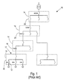
- FIG. 1 shows a schematic illustration of an examplary prior art power distribution system 10.
- Prior art power distribution system 10 includes a plurality of circuit breakers 12.
- One branch 17 of prior art power distribution system 10 includes a plurality of levels 14.
- the plurality of distribution levels include a first level 16 having circuit breakers included in a distribution board, a second level 18 having circuit breakers included in a sub-distribution switchboard, a third level 20 having circuit breakers included in a power distribution switchboard, and a fourth level 22 having circuit breakers included in a main switchboard.
- first level 16 includes 20-ampere circuit breakers
- second level 18 includes a 100-ampere circuit breaker
- third level includes a 400-ampere circuit breaker downstream of a 1200-ampere circuit breaker
- fourth level includes a 4000-ampere circuit breaker.
- Such a contemporary system as prior art power distribution system 10 fails to clear a fault such that a fault continues to flow through the system until it passes through a breaker that is sensitive enough to detect the fault.
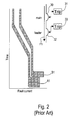
- a larger upstream overcurrent device or circuit breaker 30 must be less sensitive and slower than a smaller downstream device or circuit breaker 32.
- Each of upstream circuit breaker 30 and downstream circuit breaker 32 are connected to an electronic trip device 31, 33 to provide overcurrent protection functions that provides logic and information processing to make trip decisions.
- Figure 2 shows a fault current present in upstream circuit breaker 30 and downstream circuit breaker 32 on a log plot over a period of time from committing to trip to clearing the fault current.
- upstream circuit breaker 30 does not trip until after a time period to allow time for downstream circuit breaker 32 to trip, shown on axis A1, during flow of the fault current, as shown by arrow F1.
- Sensitivity and speed must be undesirably dictated by coordination requirements, such as, the time delay between upstream breaker 30 and downstream breaker 32, rather than protection or safety requirements in a cascaded power distribution system. This increases the risk of damage to the system, such as failure to timely clear a fault, increasing let-through. As settings get bigger and the breakers get slower a time delay to detect flow and determine if the flow is too much increases while a breaker waits for a breaker downstream to trip. Minimizing the let-through is extremely desirable because let-through of a fault is dangerous and causes failure/melting of expensive components of a power distribution system.
- Prior art zone selective interlocking (ZSI) systems only provide (yes/no) communication between two overcurrent devices in series.
- a bottom (load side) device or downstream circuit breaker 232 communicates to an upper (line side) device or upstream circuit breaker 230 whether it is reacting to a fault or not.
- upstream circuit breaker 230 does not receive a signal that downstream circuit breaker 232 detects a fault it knows to accelerate itself to faster operation.
- Each of upstream circuit breaker 230 and downstream circuit breaker 232 has an electronic trip device 231, 233 to provide overcurrent protection functions that provides logic and information processing to make trip decisions.
- ZSI systems undesirably only allow improvement of delays between upstream circuit breakers and downstream circuit breakers as long as a fault is high enough to be over a predetermined pick up threshold and fails to increase sensitivity of upstream circuit breakers, such as upstream circuit breaker 230, due to tolerance and load sustaining needs over prior art system 10.
- breakers may trip for faults that are another breaker's responsibility.
- Each breaker of system 10 makes independent decisions. This also decreases the efficiency of the system, such as through untimely opening of circuit breakers and nuisance tripping, and can increase the extent and duration of electrical service interruption in the event of a fault.
- circuit protection systems incorporated into power distribution systems that decrease the risk of damage and increase efficiency of the power distribution system.
- circuit protection systems that improve delays between upstream circuit breakers and downstream circuit breakers and increases sensitivity of upstream circuit breakers over the prior art.
- a protection system for a power distribution system with one or more zones that includes at least one power-switching device connected to a power or current sensing device and a communications device.
- the power-switching device is communicatively coupled to at least one processing device.
- the at least one processing device is adapted to execute a plurality of protective functions for a zone based on information of power conditions within the zone and predetermined protective requirements of the zone.
- a protection system that includes a master power-switching device communicatively coupled to one or more conterminous power-switching devices that bound a zone of protection.
- the master power-switching device is associated with a processor that is adapted to access information from the conterminous power-switching devices to perform zone based protection and control functions based on information communicated from the conterminous power-switching devices.
- the processor may include bus differential function.
- the one or more zones may be a plurality of zones that are bounded by source and load automatic over current protective devices.
- the one or more zones may be a plurality of zones that overlap via one or more tie power-switching devices and outgoing feeder or a source zone to a main of a load zone.
- the communications device may communicate with a communication interface that is communicatively coupleable to at least one secondary power-switching device.
- the communications device may be communicatively coupled to a second communications device to communicate a presence or absence of a fault condition sensed by the at least one secondary power-switching device.
- the at least one power-switching device may be at a slower setting than the at least one secondary power-switching device in the presence of the fault condition and a setting equal to the at least one second power-switching device in the absence of the fault condition.
- the at least one power-switching device may be at least a master power-switching device and a secondary power-switching device, where the master power-switching device may perform differential protection by calculations based on its own current information and information communicated thereto by the secondary power-switching device in a master power-switching device's zone, and where the master power-switching device may determine the presence of a fault within the master power-switching device's zone based upon a result of the calculations.
- the power or current sensing device may be a sensor that detects current flow and is communicatively coupled to the communications device.
- the at least one power-switching device may be a plurality of power-switching devices, and each of the plurality of power-switching devices may be a master power-switching device for power-switching devices connected directly downstream thereof and a secondary power-switching device to secondary power-switching devices immediately upstream thereof.
- the processor may include bus differential function.
- the zone of protection may be bounded by source and load automatic over current protective devices.
- the zone of protection may overlap a second zone of protection via one or more tie power-switching devices and outgoing feeder or a source zone to a main of a load zone.
- the master power-switching device may have a communications device that communicates with a communication interface that is communicatively coupleable to one or more conterminous power-switching devices.
- the master power-switching device may have a communications device that is communicatively coupled to a second communications device of the one or more conterminous power-switching devices to communicate a presence or absence of a fault condition sensed by the one or more conterminous power-switching devices.
- the master power-switching device may be at a slower setting than the one or more conterminous power-switching devices in the presence of the fault condition and a setting equal to the one or more conterminous power-switching devices in the absence of the fault condition.
- the zone based protection and the control functions may be selected from the group consisting of bus differential calculations, partial differential, zone selective interlocking, ground fault differential, single point over current, and any combinations thereof.
- the master power-switching device may have a power or current sensing device that is a sensor that detects current flow and is communicatively coupled to a communications device.
- the master power-switching device may be upstream of the one or more conterminous power-switching devices.
- System 110 distributes power through a number or plurality of power switching devices or circuit breakers 114 to branch circuits 116 to one or more loads 118.
- Each of circuit breakers 114 has a sensing device and a communicating device.
- Circuit breakers 114 may additionally include a processor.
- Circuit breakers such as, for example, branch circuit breakers 122 that do not have any circuit breakers downstream relative to power flow, may not have the processing device.
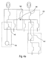
- Circuit breakers 114 may include source overcurrent protection devices or circuit breakers 140 and branch overcurrent protection devices or circuit breakers 142, as shown in Figure 4a .
- Source overcurrent protection devices 140 are located where current is expected to come in from a source. In some cases, source overcurrent protection devices 140 can also be a load or outgoing zone as in the case of a tie overcurrent protection device 144.
- Branch overcurrent protection devices or circuit breakers 142 are the last devices that feed an end use load 156 and have no further distribution thereunder.
- System 110 is a zone controlled and fully integrated protection, monitoring, and control system.
- One or more zones 120 are bounded by source and load automatic over current protective devices or circuit breakers 114. Zones 120 may overlap via tie circuits breakers 144 and outgoing feeder or a source zone to a main of a load zone, such as, for example, overlapping zone 146, as shown in Figure 4a .
- System 110 is configured so that each of circuit breakers 114 acts as a master breaker, such as, for example, one of master circuit breakers in System 110 is a master breaker 115, for breakers connected directly below or downstream of the master breaker and a secondary breaker, such as, for example, one of secondary circuit breakers in System 110 is a secondary breaker 113, to circuit breakers immediately above or upstream of the master breaker.
- a secondary breaker is below or downstream of a master breaker.
- a master breaker is above or upstream of a secondary breaker.
- Each of circuit breakers 114 may sense currents and/or voltages via the sensing device.
- Each of circuit breakers 114 may communicate via the communicating device the sensed currents and/or voltages to master breakers.
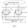
- Master breakers use information communicated by secondary or conterminous circuit breakers, as illustrated by arrow Z1 in Figure 5 , to perform differential protection for one of zones 120 via a processor 158. Differential protection is based on Kirchoff's current law that states that all the current into a junction or node must equal all the current out of the node.
- a master circuit breaker performs calculations based on its own current information and information communicated thereto by secondary breakers in a master circuit breaker's zone. Based upon the result of the calculations, a master breaker determines the presence of an excessive current or fault within the master circuit breaker's zone or is passing through to a lower zone. Zones 120 have incoming and outgoing currents.
- the instantaneous vector sum of all the currents should equal zero plus a predetermined measurement error. If the sum exceeds zero by more than the predetermined measurement error then there is an unaccounted current within the zone which is classified as a fault.
- the master breaker To the master breaker to make the calculation it must have synchronized instantaneous values from each entrance and exit in the master circuit breaker's zone, or synchronized phasor values for each input/output (I/O) point.
- Each secondary circuit breaker must measure and communicate measurements to a master breaker. Each master breaker receives the measurements and processes for its assigned zone. Sensitivity and speed of this decision is based on the sensing and computational limits of the hardware, not selectivity constraints imposed by speed or delays of circuit breakers 114.
- the processor of the master breaker may include an algorithm to adjust a time period to any time period between the master breaker and the secondary circuit breakers to interrupt power flow, based on the conditions detected by the master and secondary circuit breakers and the calculations based on its own current information and information communicated thereto by secondary breakers in a master circuit breaker's zone.
- the master breaker operates at a faster setting that may be equal to the secondary circuit breakers' time setting when the secondary circuit breakers indicate the absence of a fault condition.
- the user or architect must define at least one master circuit breaker for each of one or more zones 120.
- the master circuit breaker may be between the zone and the source and not a circuit breaker between the zone and a load. If a zone consists of one circuit breaker and a load then the one of circuit breaker is its own master for that zone comprised only of itself.
- sensitivity in system 110 may be improved by an addition of a master breaker that includes bus differential 87B function.
- the bus differential sums multiple input and output currents to find a fault within the zone.
- the processing device or logic 340 for bus differential calculation (87B) or function uses synchronized phasor values for all incoming and out going currents so a sum total node current can be calculated.
- the bus differential may be made sensitive to smaller faults, even less than the full load current of the circuit, only as limited by the accuracy of the sensing mechanism but not limited by coordination requirements, but may, in some cases not be useful for higher fault values due to current transformer saturation.
- bus differential function into system 110 provides capability to detect a complete range of potential fault values as limited by the interrupting rating of the circuit breaker, such as, for example, in some cases as high as 200,000 amperes and further may encompass zero sequence (ground fault) faults in addition to the phase protection, ensuring selectivity between ground faults and phase protection.
- processing device or logic 340 for bus differential calculation (87B) or function increases sensitivity, as shown by curve C3, over larger upstream overcurrent device or circuit breaker 30 and smaller downstream device or circuit breaker 32 of prior art distribution system 10, as shown in Figure 2 , in a fault condition.
- the communicating device may be, such as, for example, one or more nodes 150.
- Sensor 152 may be any sensor that detects current flow. Sensors may be integral with the breaker or mounted externally of the breaker. Sensor 152 may provide an analog information signal proportional to current magnitude. The analog information signal is sent to node 150 which digitizes and packetizes the analog information signal for communication purposes and sends it to a communication interface 154 which then communicates the information to a master breaker.
- the communication interface 154 receives multiple pieces of information from multiple points in circuit breakers 114 and may package the information. A hierarchy of circuit breakers 114 may be established automatically via the processor by logic, manual interface, architecture, or any combination thereof.
- Communication interface 154 may include power line carrier communication, a wireless communication interface similar to a mobile telephone network, or any other communication interface.
- Distribution system components 156 may be loads, cables, any distribution system component, or any combination thereof. In the case that there are more than one of circuit breakers 114 that include processors, each processor has an algorithm to be executed locally for secondary breakers.
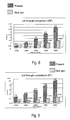
- Model distribution system 410 included a plurality of circuit breakers 414 and a transformer 415. Let-through characteristics of a MS main circuit breaker MS Main of model distribution system 410 were analyzed based on prior art cascaded control methodology for circuit breakers and compared to a zone distribution system as described herein optimized for selectivity and protection limited only by inherent capabilities, for example, sensing technology and memory. Comparison based on amperes squared times second, which is a mathematical value proportional to energy, for two kinds of fault scenarios: ground faults and face faults are shown in Figures 8 and 9 . As shown in Figures 8 and 9 , a zone power distribution system as described herein may reduce let-through by 60%-75% over prior art cascaded control and zone selective interlocking methodology.
Landscapes
- Emergency Protection Circuit Devices (AREA)
- Remote Monitoring And Control Of Power-Distribution Networks (AREA)
Applications Claiming Priority (1)
| Application Number | Priority Date | Filing Date | Title |
|---|---|---|---|
| US11/646,635 US7576963B2 (en) | 2006-12-28 | 2006-12-28 | Circuit protection system |
Publications (3)
| Publication Number | Publication Date |
|---|---|
| EP1939999A2 true EP1939999A2 (de) | 2008-07-02 |
| EP1939999A3 EP1939999A3 (de) | 2018-06-13 |
| EP1939999B1 EP1939999B1 (de) | 2020-05-13 |
Family
ID=39205019
Family Applications (1)
| Application Number | Title | Priority Date | Filing Date |
|---|---|---|---|
| EP07123231.8A Active EP1939999B1 (de) | 2006-12-28 | 2007-12-14 | Schaltkreisschutzsystem |
Country Status (3)
| Country | Link |
|---|---|
| US (1) | US7576963B2 (de) |
| EP (1) | EP1939999B1 (de) |
| CN (2) | CN105207183A (de) |
Cited By (4)
| Publication number | Priority date | Publication date | Assignee | Title |
|---|---|---|---|---|
| WO2016071070A1 (de) * | 2014-11-05 | 2016-05-12 | Siemens Ag Österreich | Trennen von fehlerhaften netzabschnitten eines niederspannungsnetzes von weiteren netzabschnitten |
| CN106058831A (zh) * | 2016-08-05 | 2016-10-26 | 江苏方天电力技术有限公司 | 一种自适应配电网的智能分布式快速保护及故障隔离方法 |
| CN106058830A (zh) * | 2016-07-26 | 2016-10-26 | 华北电力大学 | 一种含dg配电网电流保护系统及方法 |
| CN106253250A (zh) * | 2016-08-23 | 2016-12-21 | 江苏方天电力技术有限公司 | 一种智能配电网分布式快速保护系统及保护方法 |
Families Citing this family (21)
| Publication number | Priority date | Publication date | Assignee | Title |
|---|---|---|---|---|
| US20110172840A1 (en) * | 2005-11-30 | 2011-07-14 | Radoslaw Narel | Centrally controlled protection system having reduced energy let-through mode |
| US7542256B2 (en) * | 2006-12-29 | 2009-06-02 | General Electric Company | Relay device and corresponding method |
| US20090262471A1 (en) * | 2008-04-18 | 2009-10-22 | Colorado Vnet Llc | Arc Fault Circuit Interrupter (AFCI) Support |
| US8207742B2 (en) * | 2008-12-31 | 2012-06-26 | General Electric Company | Directional zone select interlock method |
| JP5466092B2 (ja) * | 2010-06-16 | 2014-04-09 | 株式会社日立製作所 | 多端子送電線保護継電システム |
| US9705329B2 (en) * | 2012-06-29 | 2017-07-11 | Operation Technology, Inc. | Proactive intelligent load shedding |
| US10067199B2 (en) | 2013-01-30 | 2018-09-04 | Eaton Intelligent Power Limited | Electric power distribution system including metering function and method of evaluating energy metering |
| US9897656B2 (en) * | 2013-05-16 | 2018-02-20 | Carrier Corporation | Method for sensing welded contacts on a switching device |
| DE102014206249B4 (de) * | 2014-04-02 | 2023-03-23 | Siemens Aktiengesellschaft | Verfahren zum selektiven Abschalten eines Schalters einer Schalteranordnung zur Stromverteilung und entsprechende Schalteranordnung |
| GB2527534A (en) | 2014-06-24 | 2015-12-30 | Eaton Ind Netherlands Bv | Selective circuit breaker |
| US20160049788A1 (en) * | 2014-08-15 | 2016-02-18 | Ragingwire Data Centers, Inc. | Electrical power bypass tool and method |
| US9837812B2 (en) | 2014-11-20 | 2017-12-05 | General Electric Company | Power distribution systems and methods of operating power distribution systems with partial differential protection |
| US20170248638A1 (en) * | 2016-02-26 | 2017-08-31 | Engineering Systems Inc. | Test measurement system and method for using same in low voltage systems |
| US10916936B2 (en) * | 2017-10-04 | 2021-02-09 | Mohammad Rezaei Jegarluei | Circuit breaker failure protection in a power substation |
| CN113946199B (zh) * | 2020-07-15 | 2024-07-05 | 台达电子企业管理(上海)有限公司 | 供电系统 |
| CN114884342A (zh) | 2018-02-01 | 2022-08-09 | 台达电子企业管理(上海)有限公司 | 主板上芯片供电系统 |
| KR102087143B1 (ko) * | 2018-03-06 | 2020-03-10 | 엘에스산전 주식회사 | 저압 계통에서 복수의 회로차단기의 보호 협조 장치 |
| CN110474288B (zh) * | 2019-09-02 | 2021-06-25 | 广东韶钢松山股份有限公司 | 可编程微机保护装置 |
| CN118693988A (zh) * | 2023-03-24 | 2024-09-24 | 施耐德电气工业公司 | 配电设备及其操作方法 |
| CN119448178B (zh) * | 2023-08-02 | 2026-01-09 | 上海良信电器股份有限公司 | 一种断路器装置、断路器控制方法 |
| WO2025265106A1 (en) * | 2024-06-21 | 2025-12-26 | Bae Systems Controls Inc. | Remote activiation and configuation of protection devices |
Family Cites Families (8)
| Publication number | Priority date | Publication date | Assignee | Title |
|---|---|---|---|---|
| IT1286463B1 (it) * | 1996-12-10 | 1998-07-08 | Sace Spa | Metodo per la misura della potenza assorbita da un carico in impianti di distribuzione elettrica |
| US5995911A (en) * | 1997-02-12 | 1999-11-30 | Power Measurement Ltd. | Digital sensor apparatus and system for protection, control, and management of electricity distribution systems |
| US6008971A (en) * | 1998-03-23 | 1999-12-28 | Electric Boat Corporation | Fault protection arrangement for electric power distribution systems |
| US5905616A (en) * | 1998-06-01 | 1999-05-18 | Square D Company | Load selectivity system for use with electronic trip circuit breakers |
| CN1093330C (zh) * | 1999-06-22 | 2002-10-23 | 韩利海 | 母线综合保护方法 |
| US7747354B2 (en) * | 2003-01-06 | 2010-06-29 | General Electric Company | Circuit protection system |
| CN100559316C (zh) * | 2003-01-06 | 2009-11-11 | 通用电气公司 | 电路保护系统 |
| US7755872B2 (en) * | 2006-09-14 | 2010-07-13 | Schweitzer Engineering Laboratories, Inc. | System, method and device to preserve protection communication active during a bypass operation |
-
2006
- 2006-12-28 US US11/646,635 patent/US7576963B2/en active Active
-
2007
- 2007-12-14 EP EP07123231.8A patent/EP1939999B1/de active Active
- 2007-12-28 CN CN201510645052.9A patent/CN105207183A/zh active Pending
- 2007-12-28 CN CNA2007103066890A patent/CN101212137A/zh active Pending
Cited By (7)
| Publication number | Priority date | Publication date | Assignee | Title |
|---|---|---|---|---|
| WO2016071070A1 (de) * | 2014-11-05 | 2016-05-12 | Siemens Ag Österreich | Trennen von fehlerhaften netzabschnitten eines niederspannungsnetzes von weiteren netzabschnitten |
| CN106058830A (zh) * | 2016-07-26 | 2016-10-26 | 华北电力大学 | 一种含dg配电网电流保护系统及方法 |
| CN106058830B (zh) * | 2016-07-26 | 2018-05-18 | 华北电力大学 | 一种含dg配电网电流保护系统及方法 |
| CN106058831A (zh) * | 2016-08-05 | 2016-10-26 | 江苏方天电力技术有限公司 | 一种自适应配电网的智能分布式快速保护及故障隔离方法 |
| CN106058831B (zh) * | 2016-08-05 | 2018-06-29 | 江苏方天电力技术有限公司 | 一种自适应配电网的智能分布式快速保护及故障隔离方法 |
| CN106253250A (zh) * | 2016-08-23 | 2016-12-21 | 江苏方天电力技术有限公司 | 一种智能配电网分布式快速保护系统及保护方法 |
| CN106253250B (zh) * | 2016-08-23 | 2019-02-05 | 江苏方天电力技术有限公司 | 一种智能配电网分布式快速保护系统及保护方法 |
Also Published As
| Publication number | Publication date |
|---|---|
| CN101212137A (zh) | 2008-07-02 |
| US7576963B2 (en) | 2009-08-18 |
| EP1939999B1 (de) | 2020-05-13 |
| EP1939999A3 (de) | 2018-06-13 |
| US20080158752A1 (en) | 2008-07-03 |
| CN105207183A (zh) | 2015-12-30 |
Similar Documents
| Publication | Publication Date | Title |
|---|---|---|
| EP1939999B1 (de) | Schaltkreisschutzsystem | |
| CA2677330C (en) | Fuse saving power distribution system fault protection | |
| US10418804B2 (en) | Fault protection system and method for an electrical power distribution system | |
| EP1940000B1 (de) | Stromkreisschutzsystem | |
| US7102866B2 (en) | Power line protection | |
| US6914762B2 (en) | Protection of electrical power lines | |
| JP2018064416A (ja) | 並行2回線送電線保護システム | |
| EP1335470B1 (de) | Distanzrelaissystem mit Richtungsvergleich | |
| JP5208684B2 (ja) | 地絡保護継電システム | |
| US20250087992A1 (en) | Automated tightly-stacked protection coordination |
Legal Events
| Date | Code | Title | Description |
|---|---|---|---|
| PUAI | Public reference made under article 153(3) epc to a published international application that has entered the european phase |
Free format text: ORIGINAL CODE: 0009012 |
|
| AK | Designated contracting states |
Kind code of ref document: A2 Designated state(s): AT BE BG CH CY CZ DE DK EE ES FI FR GB GR HU IE IS IT LI LT LU LV MC MT NL PL PT RO SE SI SK TR |
|
| AX | Request for extension of the european patent |
Extension state: AL BA HR MK RS |
|
| PUAL | Search report despatched |
Free format text: ORIGINAL CODE: 0009013 |
|
| AK | Designated contracting states |
Kind code of ref document: A3 Designated state(s): AT BE BG CH CY CZ DE DK EE ES FI FR GB GR HU IE IS IT LI LT LU LV MC MT NL PL PT RO SE SI SK TR |
|
| AX | Request for extension of the european patent |
Extension state: AL BA HR MK RS |
|
| RIC1 | Information provided on ipc code assigned before grant |
Ipc: H02H 3/30 20060101ALI20180504BHEP Ipc: H02H 7/30 20060101AFI20180504BHEP Ipc: H02H 7/26 20060101ALI20180504BHEP |
|
| STAA | Information on the status of an ep patent application or granted ep patent |
Free format text: STATUS: THE APPLICATION HAS BEEN PUBLISHED |
|
| AKY | No designation fees paid | ||
| AXX | Extension fees paid |
Extension state: AL Extension state: RS Extension state: HR Extension state: MK Extension state: BA |
|
| REG | Reference to a national code |
Ref country code: DE Ref legal event code: R108 |
|
| RAP1 | Party data changed (applicant data changed or rights of an application transferred) |
Owner name: ABB SCHWEIZ AG |
|
| STAA | Information on the status of an ep patent application or granted ep patent |
Free format text: STATUS: REQUEST FOR EXAMINATION WAS MADE |
|
| 17P | Request for examination filed |
Effective date: 20190401 |
|
| RBV | Designated contracting states (corrected) |
Designated state(s): AT DE FR GB IT |
|
| STAA | Information on the status of an ep patent application or granted ep patent |
Free format text: STATUS: EXAMINATION IS IN PROGRESS |
|
| RBV | Designated contracting states (corrected) |
Designated state(s): AT BE BG CH CY CZ DE DK EE ES FI FR GB GR HU IE IS IT LI LT LU LV MC MT NL PL PT RO SE SI SK TR |
|
| 17Q | First examination report despatched |
Effective date: 20190514 |
|
| GRAP | Despatch of communication of intention to grant a patent |
Free format text: ORIGINAL CODE: EPIDOSNIGR1 |
|
| STAA | Information on the status of an ep patent application or granted ep patent |
Free format text: STATUS: GRANT OF PATENT IS INTENDED |
|
| INTG | Intention to grant announced |
Effective date: 20200107 |
|
| GRAS | Grant fee paid |
Free format text: ORIGINAL CODE: EPIDOSNIGR3 |
|
| GRAA | (expected) grant |
Free format text: ORIGINAL CODE: 0009210 |
|
| STAA | Information on the status of an ep patent application or granted ep patent |
Free format text: STATUS: THE PATENT HAS BEEN GRANTED |
|
| AK | Designated contracting states |
Kind code of ref document: B1 Designated state(s): AT BE BG CH CY CZ DE DK EE ES FI FR GB GR HU IE IS IT LI LT LU LV MC MT NL PL PT RO SE SI SK TR |
|
| REG | Reference to a national code |
Ref country code: GB Ref legal event code: FG4D |
|
| REG | Reference to a national code |
Ref country code: CH Ref legal event code: EP |
|
| REG | Reference to a national code |
Ref country code: DE Ref legal event code: R096 Ref document number: 602007060247 Country of ref document: DE |
|
| REG | Reference to a national code |
Ref country code: AT Ref legal event code: REF Ref document number: 1271507 Country of ref document: AT Kind code of ref document: T Effective date: 20200615 |
|
| REG | Reference to a national code |
Ref country code: SE Ref legal event code: TRGR |
|
| REG | Reference to a national code |
Ref country code: LT Ref legal event code: MG4D |
|
| REG | Reference to a national code |
Ref country code: NL Ref legal event code: MP Effective date: 20200513 |
|
| PG25 | Lapsed in a contracting state [announced via postgrant information from national office to epo] |
Ref country code: PT Free format text: LAPSE BECAUSE OF FAILURE TO SUBMIT A TRANSLATION OF THE DESCRIPTION OR TO PAY THE FEE WITHIN THE PRESCRIBED TIME-LIMIT Effective date: 20200914 Ref country code: LT Free format text: LAPSE BECAUSE OF FAILURE TO SUBMIT A TRANSLATION OF THE DESCRIPTION OR TO PAY THE FEE WITHIN THE PRESCRIBED TIME-LIMIT Effective date: 20200513 Ref country code: FI Free format text: LAPSE BECAUSE OF FAILURE TO SUBMIT A TRANSLATION OF THE DESCRIPTION OR TO PAY THE FEE WITHIN THE PRESCRIBED TIME-LIMIT Effective date: 20200513 Ref country code: GR Free format text: LAPSE BECAUSE OF FAILURE TO SUBMIT A TRANSLATION OF THE DESCRIPTION OR TO PAY THE FEE WITHIN THE PRESCRIBED TIME-LIMIT Effective date: 20200814 Ref country code: IS Free format text: LAPSE BECAUSE OF FAILURE TO SUBMIT A TRANSLATION OF THE DESCRIPTION OR TO PAY THE FEE WITHIN THE PRESCRIBED TIME-LIMIT Effective date: 20200913 |
|
| PG25 | Lapsed in a contracting state [announced via postgrant information from national office to epo] |
Ref country code: BG Free format text: LAPSE BECAUSE OF FAILURE TO SUBMIT A TRANSLATION OF THE DESCRIPTION OR TO PAY THE FEE WITHIN THE PRESCRIBED TIME-LIMIT Effective date: 20200813 Ref country code: LV Free format text: LAPSE BECAUSE OF FAILURE TO SUBMIT A TRANSLATION OF THE DESCRIPTION OR TO PAY THE FEE WITHIN THE PRESCRIBED TIME-LIMIT Effective date: 20200513 |
|
| REG | Reference to a national code |
Ref country code: AT Ref legal event code: MK05 Ref document number: 1271507 Country of ref document: AT Kind code of ref document: T Effective date: 20200513 |
|
| PG25 | Lapsed in a contracting state [announced via postgrant information from national office to epo] |
Ref country code: NL Free format text: LAPSE BECAUSE OF FAILURE TO SUBMIT A TRANSLATION OF THE DESCRIPTION OR TO PAY THE FEE WITHIN THE PRESCRIBED TIME-LIMIT Effective date: 20200513 |
|
| PG25 | Lapsed in a contracting state [announced via postgrant information from national office to epo] |
Ref country code: RO Free format text: LAPSE BECAUSE OF FAILURE TO SUBMIT A TRANSLATION OF THE DESCRIPTION OR TO PAY THE FEE WITHIN THE PRESCRIBED TIME-LIMIT Effective date: 20200513 Ref country code: AT Free format text: LAPSE BECAUSE OF FAILURE TO SUBMIT A TRANSLATION OF THE DESCRIPTION OR TO PAY THE FEE WITHIN THE PRESCRIBED TIME-LIMIT Effective date: 20200513 Ref country code: EE Free format text: LAPSE BECAUSE OF FAILURE TO SUBMIT A TRANSLATION OF THE DESCRIPTION OR TO PAY THE FEE WITHIN THE PRESCRIBED TIME-LIMIT Effective date: 20200513 Ref country code: CZ Free format text: LAPSE BECAUSE OF FAILURE TO SUBMIT A TRANSLATION OF THE DESCRIPTION OR TO PAY THE FEE WITHIN THE PRESCRIBED TIME-LIMIT Effective date: 20200513 Ref country code: DK Free format text: LAPSE BECAUSE OF FAILURE TO SUBMIT A TRANSLATION OF THE DESCRIPTION OR TO PAY THE FEE WITHIN THE PRESCRIBED TIME-LIMIT Effective date: 20200513 Ref country code: ES Free format text: LAPSE BECAUSE OF FAILURE TO SUBMIT A TRANSLATION OF THE DESCRIPTION OR TO PAY THE FEE WITHIN THE PRESCRIBED TIME-LIMIT Effective date: 20200513 |
|
| REG | Reference to a national code |
Ref country code: DE Ref legal event code: R097 Ref document number: 602007060247 Country of ref document: DE |
|
| PG25 | Lapsed in a contracting state [announced via postgrant information from national office to epo] |
Ref country code: SK Free format text: LAPSE BECAUSE OF FAILURE TO SUBMIT A TRANSLATION OF THE DESCRIPTION OR TO PAY THE FEE WITHIN THE PRESCRIBED TIME-LIMIT Effective date: 20200513 Ref country code: PL Free format text: LAPSE BECAUSE OF FAILURE TO SUBMIT A TRANSLATION OF THE DESCRIPTION OR TO PAY THE FEE WITHIN THE PRESCRIBED TIME-LIMIT Effective date: 20200513 |
|
| PLBE | No opposition filed within time limit |
Free format text: ORIGINAL CODE: 0009261 |
|
| STAA | Information on the status of an ep patent application or granted ep patent |
Free format text: STATUS: NO OPPOSITION FILED WITHIN TIME LIMIT |
|
| 26N | No opposition filed |
Effective date: 20210216 |
|
| PG25 | Lapsed in a contracting state [announced via postgrant information from national office to epo] |
Ref country code: SI Free format text: LAPSE BECAUSE OF FAILURE TO SUBMIT A TRANSLATION OF THE DESCRIPTION OR TO PAY THE FEE WITHIN THE PRESCRIBED TIME-LIMIT Effective date: 20200513 |
|
| REG | Reference to a national code |
Ref country code: CH Ref legal event code: PL |
|
| GBPC | Gb: european patent ceased through non-payment of renewal fee |
Effective date: 20201214 |
|
| PG25 | Lapsed in a contracting state [announced via postgrant information from national office to epo] |
Ref country code: MC Free format text: LAPSE BECAUSE OF FAILURE TO SUBMIT A TRANSLATION OF THE DESCRIPTION OR TO PAY THE FEE WITHIN THE PRESCRIBED TIME-LIMIT Effective date: 20200513 |
|
| REG | Reference to a national code |
Ref country code: BE Ref legal event code: MM Effective date: 20201231 |
|
| PG25 | Lapsed in a contracting state [announced via postgrant information from national office to epo] |
Ref country code: IE Free format text: LAPSE BECAUSE OF NON-PAYMENT OF DUE FEES Effective date: 20201214 Ref country code: LU Free format text: LAPSE BECAUSE OF NON-PAYMENT OF DUE FEES Effective date: 20201214 Ref country code: FR Free format text: LAPSE BECAUSE OF NON-PAYMENT OF DUE FEES Effective date: 20201231 |
|
| PG25 | Lapsed in a contracting state [announced via postgrant information from national office to epo] |
Ref country code: LI Free format text: LAPSE BECAUSE OF NON-PAYMENT OF DUE FEES Effective date: 20201231 Ref country code: CH Free format text: LAPSE BECAUSE OF NON-PAYMENT OF DUE FEES Effective date: 20201231 Ref country code: GB Free format text: LAPSE BECAUSE OF NON-PAYMENT OF DUE FEES Effective date: 20201214 |
|
| PG25 | Lapsed in a contracting state [announced via postgrant information from national office to epo] |
Ref country code: TR Free format text: LAPSE BECAUSE OF FAILURE TO SUBMIT A TRANSLATION OF THE DESCRIPTION OR TO PAY THE FEE WITHIN THE PRESCRIBED TIME-LIMIT Effective date: 20200513 Ref country code: MT Free format text: LAPSE BECAUSE OF FAILURE TO SUBMIT A TRANSLATION OF THE DESCRIPTION OR TO PAY THE FEE WITHIN THE PRESCRIBED TIME-LIMIT Effective date: 20200513 Ref country code: CY Free format text: LAPSE BECAUSE OF FAILURE TO SUBMIT A TRANSLATION OF THE DESCRIPTION OR TO PAY THE FEE WITHIN THE PRESCRIBED TIME-LIMIT Effective date: 20200513 |
|
| PG25 | Lapsed in a contracting state [announced via postgrant information from national office to epo] |
Ref country code: BE Free format text: LAPSE BECAUSE OF NON-PAYMENT OF DUE FEES Effective date: 20201231 |
|
| REG | Reference to a national code |
Ref country code: DE Ref legal event code: R081 Ref document number: 602007060247 Country of ref document: DE Owner name: ABB S.P.A., IT Free format text: FORMER OWNER: ABB SCHWEIZ AG, BADEN, CH |
|
| PG25 | Lapsed in a contracting state [announced via postgrant information from national office to epo] |
Ref country code: IS Free format text: LAPSE BECAUSE OF NON-PAYMENT OF DUE FEES Effective date: 20200913 |
|
| PGFP | Annual fee paid to national office [announced via postgrant information from national office to epo] |
Ref country code: DE Payment date: 20251211 Year of fee payment: 19 |
|
| PGFP | Annual fee paid to national office [announced via postgrant information from national office to epo] |
Ref country code: IT Payment date: 20251223 Year of fee payment: 19 |
|
| PGFP | Annual fee paid to national office [announced via postgrant information from national office to epo] |
Ref country code: SE Payment date: 20251219 Year of fee payment: 19 |