EP1939632A1 - Bewegungssensor für den Hilfsantrieb einer Fahrzeugtür - Google Patents
Bewegungssensor für den Hilfsantrieb einer Fahrzeugtür Download PDFInfo
- Publication number
- EP1939632A1 EP1939632A1 EP06127383A EP06127383A EP1939632A1 EP 1939632 A1 EP1939632 A1 EP 1939632A1 EP 06127383 A EP06127383 A EP 06127383A EP 06127383 A EP06127383 A EP 06127383A EP 1939632 A1 EP1939632 A1 EP 1939632A1
- Authority
- EP
- European Patent Office
- Prior art keywords
- target
- displacement
- electrical component
- component
- sensor according
- Prior art date
- Legal status (The legal status is an assumption and is not a legal conclusion. Google has not performed a legal analysis and makes no representation as to the accuracy of the status listed.)
- Ceased
Links
- 230000033001 locomotion Effects 0.000 title claims abstract description 29
- 230000008859 change Effects 0.000 claims abstract description 13
- 238000001514 detection method Methods 0.000 claims abstract description 12
- 230000005355 Hall effect Effects 0.000 claims abstract description 4
- 238000006073 displacement reaction Methods 0.000 claims description 26
- 239000000523 sample Substances 0.000 claims description 4
- 230000007704 transition Effects 0.000 claims description 4
- 230000009471 action Effects 0.000 description 4
- 230000005540 biological transmission Effects 0.000 description 1
- 238000013016 damping Methods 0.000 description 1
- 238000010586 diagram Methods 0.000 description 1
- 230000000694 effects Effects 0.000 description 1
- 238000000034 method Methods 0.000 description 1
- 238000005457 optimization Methods 0.000 description 1
- 230000008569 process Effects 0.000 description 1
Images


Classifications
-
- G—PHYSICS
- G01—MEASURING; TESTING
- G01P—MEASURING LINEAR OR ANGULAR SPEED, ACCELERATION, DECELERATION, OR SHOCK; INDICATING PRESENCE, ABSENCE, OR DIRECTION, OF MOVEMENT
- G01P13/00—Indicating or recording presence, absence, or direction, of movement
-
- G—PHYSICS
- G01—MEASURING; TESTING
- G01P—MEASURING LINEAR OR ANGULAR SPEED, ACCELERATION, DECELERATION, OR SHOCK; INDICATING PRESENCE, ABSENCE, OR DIRECTION, OF MOVEMENT
- G01P3/00—Measuring linear or angular speed; Measuring differences of linear or angular speeds
- G01P3/42—Devices characterised by the use of electric or magnetic means
- G01P3/44—Devices characterised by the use of electric or magnetic means for measuring angular speed
- G01P3/48—Devices characterised by the use of electric or magnetic means for measuring angular speed by measuring frequency of generated current or voltage
- G01P3/481—Devices characterised by the use of electric or magnetic means for measuring angular speed by measuring frequency of generated current or voltage of pulse signals
- G01P3/487—Devices characterised by the use of electric or magnetic means for measuring angular speed by measuring frequency of generated current or voltage of pulse signals delivered by rotating magnets
Definitions
- the present invention relates to a sensor for detecting a movement for a motorized assistance system of an opening of a motor vehicle.
- Motorized assistance systems of an opening of a motor vehicle such as the boot, the tailgate or a side door are already known. These systems generally comprise a motorized unit used to move, following a command from a user, the opening from a closed position to an open position or vice versa. Of course, any intermediate position is also conceivable.
- the movement of the opening is controlled according to the starting position and depending on the direction of movement (opening or closing) according to predefined velocity profiles.
- the latter For example for a closure of a trunk, the latter must be accelerated at a certain speed to be able to compress the seals of the trunk sufficiently to allow the engagement of the bolt in the lock of the trunk lock.
- the speed at the end of the race towards the fully open position must be small in order not to damage the hinges, in particular by an excessive speed at the end of the race.
- the opening or closing of the opening can not only be performed by the motorized unit, but also by a manual action of the user.
- the user can close the trunk either by an electrical command that triggers the start of the motorized unit to drive the trunk to the closed position or by simply pressing on the trunk for manual closing.
- trunk position sensors which are for example integrated into the motorized unit.
- the present invention aims to provide a sensor for detecting a movement for a motorized assistance system of an opening of a motor vehicle whose power consumption is better controlled.
- a motor vehicle 1 comprising an opening 2 such as a tailgate.
- opening 2 such as a tailgate.
- opening of a motor vehicle it also includes the trunk or the side doors of the vehicle.
- This vehicle is equipped with a motorized assistance system 3 of an opening of a motor vehicle.
- one end of the system 3 is connected to a first articulation 4 to the vehicle body 5 and the other end is connected to a second articulation 6 at the tailgate 2.
- This motorized assistance system 3 makes it possible to bring the tailgate 2 from a predetermined starting position, for example a closed position or an open position, to an arrival position such as an open position or a closed position.
- a predetermined starting position for example a closed position or an open position
- an arrival position such as an open position or a closed position.
- the starting and finishing positions are not necessarily end positions of the tailgate, but can also be any intermediate position.
- This motor assistance system 3 is designed to also allow manual opening of the tailgate 3 by a user.
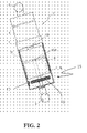
- the motorized assistance system 3 comprises two housing portions 7 and 8 of tubular shape and inserted into one another so as to extend and shorten telescopically.
- the first housing portion 7 has a larger diameter and houses an electric motor 9.
- This motor has an output shaft 10 which is engaged on a side 11 with a gearbox 12.
- This gearbox 12 has a output shaft 13 which is engaged with a screw-and-nut drive (not shown).
- the output shaft 10 of the electric motor 9 is connected to a sensor 15 for detecting a displacement according to the invention.
- the senor is placed in the motor assistance system before the clutch, that is to say that it is always linked in movement with the tailgate or that it is arranged separately, for example in a hinge.
- the sensor 15 comprises a target 16 intended to be linked in motion to the opening 2 whose displacement must be detected and at least one, preferably two electrical components 17 and 18 which interact with the target 16 so as to generate a signal of characteristic output of the displacement of the target 16.
- the target 16 is preferably a magnetic target, for example in the form of a magnetic disk with a north pole 19 and with a south pole 20 in the form of semicircles arranged alternately.
- a magnetic target for example in the form of a magnetic disk with a north pole 19 and with a south pole 20 in the form of semicircles arranged alternately.
- This disc is carried by the output shaft 10 of the motor 9 and thus rotated by a displacement of the opening 2.
- the electrical component or components 17, 18 are able to measure a change in the magnetic field due to a movement of the target 16. These are, for example, Hall effect probes.
- These components 17 and 18 are arranged vis-à-vis the magnetic disk 16 and preferably carried by the housing 7 (see figure 2 ).
- the first and second electrical components 17 and 18 are angularly offset relative to the target so that a transition 22 between a North pole and a South pole can be in front of only one electrical component. at a time.
- the first 17 and second 18 electrical components are angularly offset from the target 16 by 90 °.
- the senor comprises a management unit 21 of the power supply of the component or components 17, 18, for example a programmable microprocessor.
- This unit 21 is connected to each of the components 17 and 18 to manage their power supply, in particular in a standby state, and to process and advantageously exploit the output signals of these components.
- the unit 21 is configured to supply the component 17 in standby periodically during a time interval for detecting a change of position of the target 16, the period between two intervals of time being selected so as to detect a maximum predefined movement speed of the target.
- each component has a minimum interval or duration of power required to output a reliable characteristic signal. Therefore, in the standby state, the supply interval of the components by the unit 21 corresponds essentially to this minimum duration making it possible to obtain a reliable electrical output signal to know if the target 16 and therefore the tailgate 2 has reached moved or not.
- it is essentially to detect a kind of change of state, that is to say it is desired to detect that the target 16 has been set in motion or not, the purpose being to be able to wake the sensor the as quickly as possible so as not to lose information on the position of the tailgate 2, while optimizing the power supply.
- the period of non-power supply of the components 17 and 18 is chosen as a function of the maximum speed of movement of the opening 2 and therefore of the impact of this maximum displacement speed on the displacement of the target 16. taking into account the chain of transmission of the movement of the tailgate 2 towards the target 16.
- the maximum speed of movement of the sash will define a maximum speed of displacement of the target 16.
- a period of non-power between two time intervals is advantageously between 10ms and 20ms, preferably between 11ms and 15ms.
- the management unit 21 can apply the supply intervals and the periods of non-power supply as described above to all the components at the same time.
- the unit 21 is configured to power standby only a first electrical component 17 periodically during a time interval to detect a change in position of the target, the period between two time intervals being selected so as to be able to detect a maximum predefined movement speed of the target.
- a difficulty in detecting the displacement of a target may reside in the fact that a component for example 18 is in front of a transition zone 22 between the North pole and the South pole.
- the management unit 21 is configured so that after a displacement detection of the target by the first component for example 18, only the second electrical component is powered during a period of time. time to detect a change in position of the target to confirm the detection of the first component.
- the second component 17 does not deliver a signal corresponding to a displacement of the target 16 and the unit 21 remains in standby power mode.
- the management unit 21 is configured so as to supply all the electrical components 17, 18 at all times.
- the sash motorized or manual is performed with the vehicle's propulsion engine off so that the sensor must directly feed on the reserve resources of the vehicle such as the battery.
Landscapes
- Physics & Mathematics (AREA)
- General Physics & Mathematics (AREA)
- Power-Operated Mechanisms For Wings (AREA)
Priority Applications (2)
| Application Number | Priority Date | Filing Date | Title |
|---|---|---|---|
| EP06127383A EP1939632A1 (de) | 2006-12-29 | 2006-12-29 | Bewegungssensor für den Hilfsantrieb einer Fahrzeugtür |
| PCT/EP2007/064050 WO2008083898A1 (fr) | 2006-12-29 | 2007-12-17 | Capteur de détection d'un mouvement pour un système d'assistance motorisée d'un ouvrant d'un véhicule automobile |
Applications Claiming Priority (1)
| Application Number | Priority Date | Filing Date | Title |
|---|---|---|---|
| EP06127383A EP1939632A1 (de) | 2006-12-29 | 2006-12-29 | Bewegungssensor für den Hilfsantrieb einer Fahrzeugtür |
Publications (1)
| Publication Number | Publication Date |
|---|---|
| EP1939632A1 true EP1939632A1 (de) | 2008-07-02 |
Family
ID=38134949
Family Applications (1)
| Application Number | Title | Priority Date | Filing Date |
|---|---|---|---|
| EP06127383A Ceased EP1939632A1 (de) | 2006-12-29 | 2006-12-29 | Bewegungssensor für den Hilfsantrieb einer Fahrzeugtür |
Country Status (2)
| Country | Link |
|---|---|
| EP (1) | EP1939632A1 (de) |
| WO (1) | WO2008083898A1 (de) |
Citations (3)
| Publication number | Priority date | Publication date | Assignee | Title |
|---|---|---|---|---|
| US6150781A (en) * | 1998-02-19 | 2000-11-21 | Hoerbiger Hydraulik Gmbh | Method for controlling an operating configuration for moving parts of motor vehicles |
| US20040119506A1 (en) * | 2002-09-20 | 2004-06-24 | Toshiaki Ioi | Phase detection device, dial type detection device, and phase detection method |
| EP1566510A2 (de) * | 2004-02-18 | 2005-08-24 | Aisin Seiki Kabushiki Kaisha | Steuervorrichtung für Schliess- und Öffnungskörper |
-
2006
- 2006-12-29 EP EP06127383A patent/EP1939632A1/de not_active Ceased
-
2007
- 2007-12-17 WO PCT/EP2007/064050 patent/WO2008083898A1/fr not_active Ceased
Patent Citations (3)
| Publication number | Priority date | Publication date | Assignee | Title |
|---|---|---|---|---|
| US6150781A (en) * | 1998-02-19 | 2000-11-21 | Hoerbiger Hydraulik Gmbh | Method for controlling an operating configuration for moving parts of motor vehicles |
| US20040119506A1 (en) * | 2002-09-20 | 2004-06-24 | Toshiaki Ioi | Phase detection device, dial type detection device, and phase detection method |
| EP1566510A2 (de) * | 2004-02-18 | 2005-08-24 | Aisin Seiki Kabushiki Kaisha | Steuervorrichtung für Schliess- und Öffnungskörper |
Also Published As
| Publication number | Publication date |
|---|---|
| WO2008083898A1 (fr) | 2008-07-17 |
Similar Documents
| Publication | Publication Date | Title |
|---|---|---|
| EP3018268B1 (de) | Entkuppelbarer mechanismus für motorisierte schliessvorrichtung vom typ schliesszylinder mit druckknopf | |
| FR3004771A1 (fr) | Transmission pour engin roulant a conducteur marchant, et engin roulant equipe d'une telle transmission | |
| CA2798600C (fr) | Dispositif de connexion d'un motoreducteur a une roue d'aeronef | |
| EP1882871A1 (de) | Kraftfahrzeuggetriebe mit einem magnetischen Hall-Sensor | |
| FR3073801B3 (fr) | Actionneur de boite a gants pour verrouillage electrique et deverrouillage electrique | |
| WO2012007551A1 (fr) | Dispositif d'actionnement motorisé d'ouvrant de véhicule automobile | |
| EP3677742B1 (de) | Elektromechanische vorrichtung zur betätigung eines schlosses mit versetztem bedienungsknopf | |
| EP1437260A1 (de) | Auf zwei Achsen rotierbarer Fahrzeugaussenrückspiegel | |
| FR2627222A1 (fr) | Systeme de verrouillage pour une porte automatique | |
| EP3677739B1 (de) | Steuerverfahren einer elektromechanischen vorrichtung zum betätigen einer verriegelung | |
| EP3885514B1 (de) | Elektromechanische vorrichtung zur betätigung eines schlosses mit lösung des federriegels beim öffnen des öffnungsflügels für eine vorgegebene zeit | |
| EP1422375B1 (de) | Motorischer Stellantrieb einer Abschlussvorrichtung für eine Offnung in einem Fahrzeug und entsprechende Tür und Fahrzeug | |
| EP1939632A1 (de) | Bewegungssensor für den Hilfsantrieb einer Fahrzeugtür | |
| EP1108169B1 (de) | Elektrisch gesteuerte getriebeschalteinrichtung für ein kraftfahrzeug | |
| WO2021175817A1 (fr) | Sécateur à butée mécanique | |
| FR2951673A1 (fr) | Siege de vehicule reglable | |
| WO2003044312A1 (fr) | Procede de mise en conformite avec l'ordre donne du sens d'un moteur electrique dans une installation d'occultation ou similaire tel que fermeture | |
| FR2921401A1 (fr) | Procede d'asservissement d'un systeme d'assistance motorisee d'un ouvrant d'un vehicule automobile et systeme mettant en oeuvre le procede | |
| FR2920848A1 (fr) | Procede et dispositif de commande d'un embrayage par determination du couple transmis pour un vehicule automobile. | |
| EP1759076B1 (de) | Vorrichtung zur unterstützung beim öffnen/schliessen des sensors | |
| EP1676013A1 (de) | Vorrichtung zur steuerung des öffnens eines beweglichen elements, wie zum beispiel einer rauchabzugsklappe | |
| FR2783866A1 (fr) | Electro-reducteur pour l'automatisation de volets roulants | |
| EP1643274A2 (de) | Positionsmessverfahren eines beweglichen Bauteils innerhalb eines Rahmes und Hinderniserkennung in der Nähe des Rahmes und/oder des beweglichen Bauteils | |
| EP1743999A2 (de) | Motorische Betätigungsvorrichtung für eine Schiebetür eines Kraftfahrzeuges, mit Hinderniserkennungsmitteln und Verfahren zur dessen Verwaltung. | |
| EP2099126B1 (de) | Motor mit elektronischer Steuerung der Endschalter |
Legal Events
| Date | Code | Title | Description |
|---|---|---|---|
| PUAI | Public reference made under article 153(3) epc to a published international application that has entered the european phase |
Free format text: ORIGINAL CODE: 0009012 |
|
| AK | Designated contracting states |
Kind code of ref document: A1 Designated state(s): AT BE BG CH CY CZ DE DK EE ES FI FR GB GR HU IE IS IT LI LT LU LV MC NL PL PT RO SE SI SK TR |
|
| AX | Request for extension of the european patent |
Extension state: AL BA HR MK RS |
|
| 17P | Request for examination filed |
Effective date: 20090105 |
|
| AKX | Designation fees paid |
Designated state(s): AT BE BG CH CY CZ DE DK EE ES FI FR GB GR HU IE IS IT LI LT LU LV MC NL PL PT RO SE SI SK TR |
|
| 17Q | First examination report despatched |
Effective date: 20090212 |
|
| RAP1 | Party data changed (applicant data changed or rights of an application transferred) |
Owner name: U-SHIN DEUTSCHLAND ZUGANGSSYSTEME GMBH |
|
| STAA | Information on the status of an ep patent application or granted ep patent |
Free format text: STATUS: THE APPLICATION HAS BEEN REFUSED |
|
| 18R | Application refused |
Effective date: 20141024 |