EP1939574A1 - Appareil de ventilation, appareil d'échange thermique, élément d'échange thermique et nervure correspondante - Google Patents
Appareil de ventilation, appareil d'échange thermique, élément d'échange thermique et nervure correspondante Download PDFInfo
- Publication number
- EP1939574A1 EP1939574A1 EP07116975A EP07116975A EP1939574A1 EP 1939574 A1 EP1939574 A1 EP 1939574A1 EP 07116975 A EP07116975 A EP 07116975A EP 07116975 A EP07116975 A EP 07116975A EP 1939574 A1 EP1939574 A1 EP 1939574A1
- Authority
- EP
- European Patent Office
- Prior art keywords
- heat exchange
- rib
- exchange element
- gas
- exhaust
- Prior art date
- Legal status (The legal status is an assumption and is not a legal conclusion. Google has not performed a legal analysis and makes no representation as to the accuracy of the status listed.)
- Withdrawn
Links
- 230000001788 irregular Effects 0.000 claims abstract description 18
- 238000009423 ventilation Methods 0.000 claims description 4
- 239000007789 gas Substances 0.000 description 28
- 230000007423 decrease Effects 0.000 description 5
- 230000001965 increasing effect Effects 0.000 description 4
- 230000003746 surface roughness Effects 0.000 description 4
- 238000004378 air conditioning Methods 0.000 description 2
- 230000001939 inductive effect Effects 0.000 description 2
- 239000000463 material Substances 0.000 description 2
- 230000000694 effects Effects 0.000 description 1
- 231100000989 no adverse effect Toxicity 0.000 description 1
- 230000035699 permeability Effects 0.000 description 1
- 239000011347 resin Substances 0.000 description 1
- 229920005989 resin Polymers 0.000 description 1
Images


Classifications
-
- F—MECHANICAL ENGINEERING; LIGHTING; HEATING; WEAPONS; BLASTING
- F28—HEAT EXCHANGE IN GENERAL
- F28D—HEAT-EXCHANGE APPARATUS, NOT PROVIDED FOR IN ANOTHER SUBCLASS, IN WHICH THE HEAT-EXCHANGE MEDIA DO NOT COME INTO DIRECT CONTACT
- F28D9/00—Heat-exchange apparatus having stationary plate-like or laminated conduit assemblies for both heat-exchange media, the media being in contact with different sides of a conduit wall
- F28D9/0062—Heat-exchange apparatus having stationary plate-like or laminated conduit assemblies for both heat-exchange media, the media being in contact with different sides of a conduit wall the conduits for one heat-exchange medium being formed by spaced plates with inserted elements
-
- F—MECHANICAL ENGINEERING; LIGHTING; HEATING; WEAPONS; BLASTING
- F28—HEAT EXCHANGE IN GENERAL
- F28D—HEAT-EXCHANGE APPARATUS, NOT PROVIDED FOR IN ANOTHER SUBCLASS, IN WHICH THE HEAT-EXCHANGE MEDIA DO NOT COME INTO DIRECT CONTACT
- F28D9/00—Heat-exchange apparatus having stationary plate-like or laminated conduit assemblies for both heat-exchange media, the media being in contact with different sides of a conduit wall
- F28D9/02—Heat-exchange apparatus having stationary plate-like or laminated conduit assemblies for both heat-exchange media, the media being in contact with different sides of a conduit wall the heat-exchange media travelling at an angle to one another
-
- F—MECHANICAL ENGINEERING; LIGHTING; HEATING; WEAPONS; BLASTING
- F24—HEATING; RANGES; VENTILATING
- F24F—AIR-CONDITIONING; AIR-HUMIDIFICATION; VENTILATION; USE OF AIR CURRENTS FOR SCREENING
- F24F7/00—Ventilation
- F24F7/04—Ventilation with ducting systems, e.g. by double walls; with natural circulation
- F24F7/06—Ventilation with ducting systems, e.g. by double walls; with natural circulation with forced air circulation, e.g. by fan positioning of a ventilator in or against a conduit
- F24F7/08—Ventilation with ducting systems, e.g. by double walls; with natural circulation with forced air circulation, e.g. by fan positioning of a ventilator in or against a conduit with separate ducts for supplied and exhausted air with provisions for reversal of the input and output systems
-
- F—MECHANICAL ENGINEERING; LIGHTING; HEATING; WEAPONS; BLASTING
- F28—HEAT EXCHANGE IN GENERAL
- F28F—DETAILS OF HEAT-EXCHANGE AND HEAT-TRANSFER APPARATUS, OF GENERAL APPLICATION
- F28F13/00—Arrangements for modifying heat-transfer, e.g. increasing, decreasing
- F28F13/06—Arrangements for modifying heat-transfer, e.g. increasing, decreasing by affecting the pattern of flow of the heat-exchange media
- F28F13/12—Arrangements for modifying heat-transfer, e.g. increasing, decreasing by affecting the pattern of flow of the heat-exchange media by creating turbulence, e.g. by stirring, by increasing the force of circulation
-
- F—MECHANICAL ENGINEERING; LIGHTING; HEATING; WEAPONS; BLASTING
- F28—HEAT EXCHANGE IN GENERAL
- F28F—DETAILS OF HEAT-EXCHANGE AND HEAT-TRANSFER APPARATUS, OF GENERAL APPLICATION
- F28F13/00—Arrangements for modifying heat-transfer, e.g. increasing, decreasing
- F28F13/18—Arrangements for modifying heat-transfer, e.g. increasing, decreasing by applying coatings, e.g. radiation-absorbing, radiation-reflecting; by surface treatment, e.g. polishing
- F28F13/185—Heat-exchange surfaces provided with microstructures or with porous coatings
-
- F—MECHANICAL ENGINEERING; LIGHTING; HEATING; WEAPONS; BLASTING
- F28—HEAT EXCHANGE IN GENERAL
- F28F—DETAILS OF HEAT-EXCHANGE AND HEAT-TRANSFER APPARATUS, OF GENERAL APPLICATION
- F28F3/00—Plate-like or laminated elements; Assemblies of plate-like or laminated elements
- F28F3/02—Elements or assemblies thereof with means for increasing heat-transfer area, e.g. with fins, with recesses, with corrugations
- F28F3/04—Elements or assemblies thereof with means for increasing heat-transfer area, e.g. with fins, with recesses, with corrugations the means being integral with the element
- F28F3/048—Elements or assemblies thereof with means for increasing heat-transfer area, e.g. with fins, with recesses, with corrugations the means being integral with the element in the form of ribs integral with the element or local variations in thickness of the element, e.g. grooves, microchannels
-
- F—MECHANICAL ENGINEERING; LIGHTING; HEATING; WEAPONS; BLASTING
- F28—HEAT EXCHANGE IN GENERAL
- F28F—DETAILS OF HEAT-EXCHANGE AND HEAT-TRANSFER APPARATUS, OF GENERAL APPLICATION
- F28F2250/00—Arrangements for modifying the flow of the heat exchange media, e.g. flow guiding means; Particular flow patterns
- F28F2250/10—Particular pattern of flow of the heat exchange media
- F28F2250/108—Particular pattern of flow of the heat exchange media with combined cross flow and parallel flow
Definitions
- a ventilating apparatus, a heat exchange apparatus, a heat exchange element, and a rib therefor are disclosed herein.
- Ventilating apparatus and heat exchange apparatus are known. However, they suffer from various disadvantages.
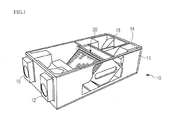
- Fig. 1 is a perspective view of internal structure of a ventilating apparatus according to an embodiment
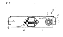
- Fig. 2 is a sectional view illustrating introduction/exhaust of outdoor air in the ventilating apparatus of Fig. 1 ;
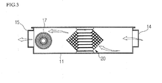
- Fig. 3 is a sectional view illustrating introduction/exhaust of indoor air in the ventilating apparatus of Fig. 1 ;
- Fig. 4 is an exploded perspective view of heat exchange elements having ribs without irregular structural surfaces
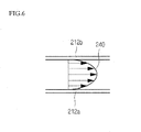
- Figs. 5 and 6 are sectional views of a velocity distribution of heat exchange gas in the heat exchange element of Fig. 4 ;
- Fig. 7 is a sectional view of heat exchange elements having ribs with irregular structural surfaces according to an embodiment
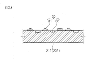
- Fig. 8 is a sectional view of a rib with an irregular surface structure in the form of an uneven portion having irregular shapes and random arrangement of an uneven portion according to an embodiment
- Fig. 9 is a perspective view of a heat exchange element having ribs with irregular structural surfaces according to an embodiment.
- a ventilating apparatus which is an air conditioning apparatus used for ventilating an enclosed space, for example, a room, functions to heat exchange incoming outdoor air with outgoing indoor air before the outdoor air is introduced indoors.
- the ventilating apparatus is a kind of air conditioning apparatus that ventilates a room, such that an indoor temperature does not decrease or increase abruptly even though the outdoor air is introduced during ventilation.
- a ventilating apparatus that performs both a heat-exchange function and a moisture-exchange function between incoming air and outgoing air is configured with a plurality of ducts that are arranged to cross one another or arranged in parallel.
- An important performance factor in a related art ventilating apparatus is to maintain the temperature and humidity of air at an inlet portion to be almost equal to the temperature and humidity of air at an outlet portion by heat exchanging and moisture exchanging the indoor air with the outdoor air.
- components of the heat exchanger constituting each of the ducts must have maximum heat transfer efficiency and moisture permeability, and each of the ducts must be arranged small and compact as possible to contact air over the broadest surface area.
- One heat exchange duct includes heat exchange sheets and ribs that maintain the multi-stacked arrangement of the heat exchange sheets. Main heat exchange is performed through heat transfer and moisture permeation between the heat exchange sheets.
- the heat exchange sheet may be made of thin paper, and thus, the heat exchange sheet may sag if it absorbs moisture.
- the ribs may be attached to the heat exchange sheet in molten resin form and then cured to thereby constitute ducts with the heat exchange sheet.
- the ribs may be provided on both sides of the heat exchange sheet, and thus different gases (these gases may be outdoor air and indoor air typically, but there is no particular limitation) flow in such a way that they cross each other or flow in an opposite direction (for example, in parallel and opposite directions to each other). In such a case, there may occur a case where pressure or flow velocity is not uniform in each duct or even in the same duct depending on specific positions.
- Fig. 1 is a perspective view of internal structure of a ventilating apparatus according to an embodiment
- Fig. 2 is a sectional view illustrating introduction/exhaust of outdoor air in the ventilating apparatus of Fig. 1
- Fig. 3 is a sectional view illustrating introduction/exhaust of indoor air in the ventilating apparatus of Fig. 1 .
- the ventilating apparatus 10 may include a case 11 forming an external shape, a heat exchanger 20 received in the case 11, an intake fan 16, shown in Fig. 2 , configured to introduce outdoor air, and an exhaust fan 17, as shown in Fig. 3 configured to introduce indoor air.
- the heat exchanger 20 may heat exchange incoming outdoor air and outgoing indoor air with each other.
- an intake air inlet 12 that introduces outdoor air and an exhaust air outlet 15 that exhausts indoor air to the outside may be provided at one side of the case 11.
- an intake air outlet 13 that discharges the introduced outdoor air to the indoor space, and an exhaust air inlet 14 that introduces the indoor air may be provided.
- An intake passage may be provided between the intake air inlet 12 and the intake air outlet 13 in the form of a duct.
- the heat exchanger 20 may be positioned in a middle portion of the intake passage or duct.
- An exhaust passage may also provided between the exhaust air inlet 14 and the exhaust air outlet 15 in the form of a duct.
- the heat exchanger 20 may be positioned in a middle portion of the exhaust passage or duct. The outdoor air introduced through the intake air inlet 12 and the indoor air introduced through the exhaust air inlet 14 may be heat exchanged with each other without being mixed, while passing through the heat exchanger 20.
- Fig. 2 is a sectional view illustrating the introduction/exhaust of outdoor air in the ventilating apparatus of Fig. 1
- Fig. 3 is a sectional view illustrating the introduction/exhaust of indoor air in the ventilating apparatus of Fig. 1
- the intake fan 16 may be mounted inside the duct at a side of the intake air outlet 13 to introduce the outdoor air.
- the outdoor air may be introduced through the intake air inlet 12 by operation of the intake fan 16, and then may be heat exchanged with the indoor air while passing through the heat exchanger 20.
- the exhaust fan 17 may be mounted inside the duct at a side of the exhaust air outlet 15 to introduce the indoor air.
- the indoor air is introduced through the exhaust inlet 14 by the operation of the exhaust fan 17, and the indoor air is then heat exchanged with the outdoor air while passing through the heat exchanger 20.
- the heat exchanger 20 may include a plurality of stacked heat exchange plates.
- the heat exchange plates may be configured such that guide ribs are disposed between heat exchange sheets.
- the combination structure of the heat exchange sheet and the guide rib may constitute a duct that guides the introduced indoor air or outdoor air.
- the duct through which the indoor air flows and the duct through which the outdoor air flows may be cross-arranged at left and right sides of the heat exchange sheet, respectively. Therefore, the outdoor air and the indoor air may be only heat exchanged with each other without being mixed, while they pass through the heat exchanger 20.
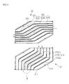
- Fig. 4 is an exploded perspective view of a heat exchange element.
- the heat exchange element may be in the shape of a hexagonal plane as a unit element.
- an intake heat exchange element 21 and an exhaust heat exchange element 22, which both may have hexagonal shapes, may be alternately stacked.
- the intake passage and the exhaust passage are provided between the intake heat exchange element 21 and the exhaust heat exchange element 22.
- the intake heat exchange element 21 may include a heat exchange sheet 211, which may be made of a thin paper material, introduction guide ribs 212, which may be disposed on one side of the heat exchange sheet 211 such that they are spaced apart by predetermined distances, and a frame 213 provided at an edge portion of the heat exchange sheet 211 to maintain the shape of the intake heat exchange element 21.
- the introduction guide ribs 212 may be divided into three sections, for example, an outdoor air intake section, an intermediate section and an outdoor air exhaust section.
- the outdoor air intake section and the outdoor air exhaust section may be disposed on both edges of the intermediate section, respectively.
- the introduction guide rib 212 of the outdoor air intake section and the outdoor air exhaust section may be bent such that it is inclined at a predetermined angle with respect to the introduction guide rib 212 of the intermediate section.
- the introduction guide rib 212 may be configured with an intake portion 212a, a straight portion 212b, and an exhaust portion 212c.
- the straight portion 212b may extend from the intake portion 212a such that it is inclined at a predetermined angle with respect to the intake portion 212a.
- the exhaust portion 212c may further extend from an end of the straight portion 212b such that it is inclined at a predetermined angle with respect to the straight portion 212b.
- the exhaust heat exchange element 22 may include a heat exchange sheet 221, exhaust guide ribs 222, which may be disposed on attached to one side of the heat exchange sheet 21 such that they are spaced apart by predetermined distance, and a frame 223.
- the exhaust guide rib 222 may also be configured with an intake portion 222a, a straight portion 222b and an exhaust portion 222c.
- the intake portion 222a and the exhaust portion 222c of the exhaust guide rib 222 may be respectively inclined in directions symmetric to the intake portion 212a and the exhaust portion 212c of the introduction guide rib 212.
- the intake portion 212a of the introduction guide rib 212 may be inclined such that it crosses the intake portion 222a of the exhaust guide rib 222.
- the exhaust portions 212c and 222c may be inclined such that they cross each other in the same manner.
- the intake portion of the intake heat exchange element 21 and the intake portion of the exhaust heat exchange element 22 may cross each other, or the exhaust portion of the intake heat exchange element 21 and the exhaust portion of the exhaust heat exchange element 22 may cross each other.
- the intermediate sections of the introduction and exhaust guide ribs 212 and 222, in which heat exchange operation may be effectively performed, may be arranged in parallel, but incoming air and outgoing air flow in opposite directions to each other, respectively, which makes it possible to increase heat exchange efficiency as much as possible.
- the outdoor air and the indoor air may be heat exchanged with each other substantially more or the most in the section where they pass through the straight portions 212b and 222b than in any other section.
- the heat is sufficiently exchanged between the incoming air and the outgoing air as a length of the straight portion increases.
- this inevitably leads to a decrease of flow velocity of air.
- Figs. 5 and 6 are sectional views of a velocity distribution of heat exchange gas in the heat exchange element of Fig. 4 .
- the introduction guide rib 212 and an exhaust guide rib 222 may be provided such that they are stacked. Outdoor air is introduced along the introduction guide rib 212, and indoor air is introduced along an exhaust guide rib 222.
- ribs have the shape of a quadratic prism, four surfaces of the quadratic prism may be divided into a pair of first surfaces contacting the heat exchange sheet, and a pair of second surfaces contacting the heat exchange gas directly.
- a velocity distribution 240 of the heat exchange gas in each duct formed by the ribs may be represented as a parabolic profile because gas velocity is the highest at a center of the duct, progressively decreases far from the center, and becomes approximately 0 on the surface of the ribs.
- Fig. 7 is a sectional view of heat exchange elements having ribs with irregular structural surfaces according to an embodiment. As shown in Fig. 7 , the heat exchange elements are multi-stacked in a thickness direction. More specifically, Fig. 7 is a sectional view taken along line I-I' of Fig. 5 in case that the heat exchange elements of Fig. 5 are triply multi-stacked. The ribs of Fig. 7 each have an irregular structural surface in the form of uneven portion 30 is provided on a surface of the ribs of Fig. 5 to increase surface roughness.
- Fig. 8 is a sectional view of a rib according to an embodiment with an irregular structural surface in the form of an uneven portion having irregular shapes arranged along a surface of the ribs 212 or 222.
- the uneven portion 30, which may be arranged regularly or irregularly on side surfaces (these may be defined as “second surfaces”) of the guide rib 212 and 222 of the heat exchange element 20 according to the embodiment, is in contact with the heat exchange gas.
- top and bottom surface of the guide rib 212 and 222 (these may be defined as "first surfaces") contact the heat exchange sheet.
- the uneven portion 30 may be provided with a protrusion 31 which may protrude a predetermined distance from the surface of the rib, and a recess 32 which may be recessed a predetermined depth from the surface of the ribs.
- the protrusion 31 and the recess 32 may have various shapes, such as a circle, a polygon, or other shape.
- the irregular arrangement and irregular shape of the uneven portion 30 may be more effective for inducing a turbulent flow.
- a turbulent flow may be rapidly formed by forming the protrusion 31 and the recess 32 in various sizes and depths.
- a turbulent flow may be formed by forming a scratch or scratches on the surface of the guide rib.
- Fig. 9 is a perspective view of a heat exchange element having ribs with irregular structural surfaces according to an embodiment.
- a velocity distribution 250 of heat exchange gases flowing through each duct of the heat exchange element shows a turbulent flow type distribution in which the velocity distribution has a relatively flat profile around the center of the duct and a thickness of a boundary layer is thin, unlike the parabolic profile of Fig. 6 .
- a heat exchange element having the above configuration it may be possible to minimize duct resistance by suppressing a laminar flow and growth of a boundary layer in airflow of outdoor and indoor air passing through a heat exchanger. Therefore, heat exchange may be performed even with low flow velocity and pressure because the pressure loss in the duct may be minimized. Further, since the heat exchange gas may be introduced/exhausted smoothly at a flow velocity as low as possible, the heat exchange efficiency may be increased as well.
- Embodiments disclosed herein provide a heat exchanger for a ventilating apparatus that may increase heat exchange efficiency and reduce pressure loss by changing airflow of outdoor and indoor air passing through a heat exchange element from a laminar flow to a turbulent flow.
- ribs coupled to a heat exchange sheet generally have smooth surfaces. This smooth surface may have no adverse effect if the flow velocity of the heat exchange gas is high enough. However, in the case that the flow velocity of gas passing through the heat exchanger is low, the smooth surface may cause a boundary layer to grow excessively generating a laminar flow.
- the heat exchange gas flow is a laminar flow inside the heat exchanger, pressure loss is likely to increase at an exhaust end because the flow velocity of the gas decreases. Therefore, the heat exchange gas must be introduced at a predetermined pressure and velocity higher than an appropriate flow velocity range through an intake end for good heat exchange ultimately, which leads to the decrease of heat exchange efficiency.
- Embodiments disclosed herein also provide a heat exchanger for a ventilating apparatus that may increase heat exchange efficiency by minimizing pressure loss, and thus, securing an appropriate flow velocity of heat exchange gas even under a limited supply pressure because outdoor air and indoor air passing through the heat exchanger may flow in turbulent flow type as much as possible.
- a rib of a heat exchange element defining a heat exchange gas and guiding a flow of the heat exchange gas may include at least one first surface contacting a heat exchange sheet, and at least one second surface contacting the heat exchange gas.
- the second surface may be a structural surface where a recess portion, a protrusion portion, or a combination of the recess portion and the protrusion portion may be provided.
- the structural surface may correspond to a surface with increased surface roughness on the second surface.
- the surface roughness may be adjusted to a predetermined value that minimizes pressure drop and velocity drop of the heat exchange gas, which is possible by controlling a mean height of the structural surface.
- the mean height of the structural surface may be constant for inducing regular and smooth gas flow in a counter flow section of the heat exchange gas, for example, in a section where the rib has a straight shape.
- a protrusion portion or a recess portion of the structural surface may act as a turbulent flow generating portion to reduce a thickness of a boundary layer of gas in the duct from an aspect of overall view rather than its specific shape.
- a heat exchange element in another embodiment, includes a plurality of heat exchange sheets which are multi-stacked, and a plurality of ribs arranged between the heat exchange sheets to constitute ducts with the heat exchange sheets.
- the ribs may include a structural surface including a recess portion, a protrusion portion, or a combination of the recess portion and the protrusion portion, which generates a turbulent flow in a heat exchange gas flowing through the duct.
- the structural surface may correspond to a surface increasing surface roughness of the second surface.
- a mean height of the structural surface may correspond to a value that minimizes internal pressure drop of the heat exchange gas.
- a mean height of the structural surface may correspond to a value that minimizes internal flow velocity drop of the heat exchange gas.
- any reference in this specification to "one embodiment,” “an embodiment,” “example embodiment,” etc. means that a particular feature, structure, or characteristic described in connection with the embodiment is included in at least one embodiment of the invention.
- the appearances of such phrases in various places in the specification are not necessarily all referring to the same embodiment.
Landscapes
- Engineering & Computer Science (AREA)
- Mechanical Engineering (AREA)
- General Engineering & Computer Science (AREA)
- Physics & Mathematics (AREA)
- Thermal Sciences (AREA)
- Chemical & Material Sciences (AREA)
- Crystallography & Structural Chemistry (AREA)
- Combustion & Propulsion (AREA)
- Heat-Exchange Devices With Radiators And Conduit Assemblies (AREA)
Applications Claiming Priority (1)
| Application Number | Priority Date | Filing Date | Title |
|---|---|---|---|
| KR1020060135574A KR20080060933A (ko) | 2006-12-27 | 2006-12-27 | 환기 장치의 열교환기 |
Publications (1)
| Publication Number | Publication Date |
|---|---|
| EP1939574A1 true EP1939574A1 (fr) | 2008-07-02 |
Family
ID=39149183
Family Applications (1)
| Application Number | Title | Priority Date | Filing Date |
|---|---|---|---|
| EP07116975A Withdrawn EP1939574A1 (fr) | 2006-12-27 | 2007-09-21 | Appareil de ventilation, appareil d'échange thermique, élément d'échange thermique et nervure correspondante |
Country Status (4)
| Country | Link |
|---|---|
| US (1) | US20080156469A1 (fr) |
| EP (1) | EP1939574A1 (fr) |
| KR (1) | KR20080060933A (fr) |
| CN (1) | CN101210790A (fr) |
Cited By (1)
| Publication number | Priority date | Publication date | Assignee | Title |
|---|---|---|---|---|
| CN103954162A (zh) * | 2014-05-16 | 2014-07-30 | 中国科学院工程热物理研究所 | 一种强化微通道换热的低阻水力空化结构 |
Families Citing this family (13)
| Publication number | Priority date | Publication date | Assignee | Title |
|---|---|---|---|---|
| US8376036B2 (en) * | 2007-11-02 | 2013-02-19 | Az Evap, Llc | Air to air heat exchanger |
| KR101103397B1 (ko) * | 2009-07-03 | 2012-01-05 | 김광수 | 열교환판 |
| JP5211184B2 (ja) * | 2011-02-08 | 2013-06-12 | 株式会社日本自動車部品総合研究所 | 排気冷却用アダプタ |
| WO2013157045A1 (fr) * | 2012-04-20 | 2013-10-24 | 三菱電機株式会社 | Élément d'échange de chaleur |
| KR101341106B1 (ko) * | 2013-07-31 | 2013-12-11 | 주식회사 유한엔지니어링 | 난류 발생에 의한 열교환 효율을 높인 공기조화기 |
| CN103697736A (zh) * | 2013-12-27 | 2014-04-02 | 无锡佳龙换热器制造有限公司 | 一种高效率翅片 |
| US10132522B2 (en) * | 2014-03-31 | 2018-11-20 | Nortek Air Solutions Canada, Inc. | Systems and methods for forming spacer levels of a counter flow energy exchange assembly |
| CN106440177A (zh) * | 2016-10-19 | 2017-02-22 | 珠海格力电器股份有限公司 | 换新风装置、空调系统及控制方法 |
| US20180292146A1 (en) * | 2017-04-10 | 2018-10-11 | United Technologies Corporation | Partially additively manufactured heat exchanger |
| US11098966B2 (en) | 2018-08-08 | 2021-08-24 | Denso International America, Inc. | Header tank for heat exchanger |
| JP6881516B2 (ja) * | 2019-07-29 | 2021-06-02 | 株式会社富士通ゼネラル | 隔壁式熱交換器 |
| US12025387B2 (en) * | 2019-08-06 | 2024-07-02 | Meggitt Aerospace Limited | Turning vanes and heat exchangers and methods of making the same |
| WO2023107618A1 (fr) * | 2021-12-08 | 2023-06-15 | Worcester Polytechnic Institute | Commande de flux passif pour tourbillon captif |
Citations (5)
| Publication number | Priority date | Publication date | Assignee | Title |
|---|---|---|---|---|
| US4729428A (en) * | 1984-06-20 | 1988-03-08 | Showa Aluminum Corporation | Heat exchanger of plate fin type |
| US5803162A (en) * | 1994-04-14 | 1998-09-08 | Behr Gmbh & Co. | Heat exchanger for motor vehicle cooling exhaust gas heat exchanger with disk-shaped elements |
| DE19933426A1 (de) * | 1999-07-16 | 2001-01-25 | Clyde Bergemann Ega Gmbh | Wärmetauschermodul |
| EP1250719A2 (fr) * | 1999-12-23 | 2002-10-23 | Mannesmann AG | Dispositif realise selon une technique de microstructure et laissant circuler des agents, et systeme de cellule de combustible |
| EP1557627A1 (fr) * | 2003-12-01 | 2005-07-27 | SPX Cooling Technologies GmbH | Canal d'écoulement |
Family Cites Families (8)
| Publication number | Priority date | Publication date | Assignee | Title |
|---|---|---|---|---|
| US2640194A (en) * | 1948-07-16 | 1953-05-26 | Separator Ab | Plate heat exchanger |
| US3372743A (en) * | 1967-01-25 | 1968-03-12 | Pall Corp | Heat exchanger |
| US4116271A (en) * | 1975-02-04 | 1978-09-26 | Guido Amandus De Lepeleire | Counter-current bumped plates heat exchanger |
| US6401804B1 (en) * | 1999-01-14 | 2002-06-11 | Denso Corporation | Heat exchanger only using plural plates |
| DE19963373A1 (de) * | 1999-12-28 | 2001-07-12 | Abb Alstom Power Ch Ag | Vorrichtung zur Kühlung einer, einen Strömungskanal umgebenden Strömungskanalwand mit wenigstens einem Rippenzug |
| US6729388B2 (en) * | 2000-01-28 | 2004-05-04 | Behr Gmbh & Co. | Charge air cooler, especially for motor vehicles |
| CA2639055A1 (fr) * | 2003-01-17 | 2004-07-17 | Venmar Ventilation Inc. | Piece d'espacement empilable pour noyau de recuperation d'energie |
| JP2006105577A (ja) * | 2004-09-08 | 2006-04-20 | Usui Kokusai Sangyo Kaisha Ltd | フィン構造体および該フィン構造体を内装した伝熱管並びに該伝熱管を組込んだ熱交換器 |
-
2006
- 2006-12-27 KR KR1020060135574A patent/KR20080060933A/ko not_active Application Discontinuation
-
2007
- 2007-09-11 US US11/853,132 patent/US20080156469A1/en not_active Abandoned
- 2007-09-21 CN CNA2007101526033A patent/CN101210790A/zh active Pending
- 2007-09-21 EP EP07116975A patent/EP1939574A1/fr not_active Withdrawn
Patent Citations (5)
| Publication number | Priority date | Publication date | Assignee | Title |
|---|---|---|---|---|
| US4729428A (en) * | 1984-06-20 | 1988-03-08 | Showa Aluminum Corporation | Heat exchanger of plate fin type |
| US5803162A (en) * | 1994-04-14 | 1998-09-08 | Behr Gmbh & Co. | Heat exchanger for motor vehicle cooling exhaust gas heat exchanger with disk-shaped elements |
| DE19933426A1 (de) * | 1999-07-16 | 2001-01-25 | Clyde Bergemann Ega Gmbh | Wärmetauschermodul |
| EP1250719A2 (fr) * | 1999-12-23 | 2002-10-23 | Mannesmann AG | Dispositif realise selon une technique de microstructure et laissant circuler des agents, et systeme de cellule de combustible |
| EP1557627A1 (fr) * | 2003-12-01 | 2005-07-27 | SPX Cooling Technologies GmbH | Canal d'écoulement |
Cited By (2)
| Publication number | Priority date | Publication date | Assignee | Title |
|---|---|---|---|---|
| CN103954162A (zh) * | 2014-05-16 | 2014-07-30 | 中国科学院工程热物理研究所 | 一种强化微通道换热的低阻水力空化结构 |
| CN103954162B (zh) * | 2014-05-16 | 2015-10-21 | 中国科学院工程热物理研究所 | 一种强化微通道换热的低阻水力空化结构 |
Also Published As
| Publication number | Publication date |
|---|---|
| US20080156469A1 (en) | 2008-07-03 |
| KR20080060933A (ko) | 2008-07-02 |
| CN101210790A (zh) | 2008-07-02 |
Similar Documents
| Publication | Publication Date | Title |
|---|---|---|
| EP1939574A1 (fr) | Appareil de ventilation, appareil d'échange thermique, élément d'échange thermique et nervure correspondante | |
| EP1939571A2 (fr) | Élément d'échange thermique pour appareil de ventilation | |
| US20060260791A1 (en) | Ventilator | |
| KR100617078B1 (ko) | 콤팩트형 환기시스템 | |
| US20080156470A1 (en) | Ventilating apparatus, heat exchange apparatus, heat exchange element therefor | |
| CN100449250C (zh) | 通风系统的热交换器 | |
| JP2013113493A (ja) | 熱交換素子とそれを用いた熱交換換気機器 | |
| KR20080073488A (ko) | 환기장치 | |
| WO2002081974A1 (fr) | Appareil de climatisation | |
| EP1704377B1 (fr) | Echangeur thermique destine a un ventilateur | |
| KR101189950B1 (ko) | 환기 장치 및 환기 장치의 열교환기 | |
| EP1680638B1 (fr) | Echangeur de chaleur pour ventilateur | |
| CN210399238U (zh) | 一种空调器室外机以及空调器 | |
| JP4196442B2 (ja) | 熱交換器 | |
| KR100542941B1 (ko) | 환기장치용 열교환기 | |
| JP4391116B2 (ja) | 熱交換換気装置 | |
| WO2005036067A1 (fr) | Ventilateur | |
| JP2003287239A (ja) | 天井埋込形空気調和機 | |
| CN212777645U (zh) | 空调机 | |
| KR20240060368A (ko) | 전열교환기와 이를 이용한 열회수장치. | |
| KR100898926B1 (ko) | 환기 장치용 열교환기 | |
| JPH1038302A (ja) | 空気調和機の室内ユニット | |
| KR100867787B1 (ko) | 환기 장치의 열교환기 | |
| KR20240115527A (ko) | 전열교환기와 이를 이용한 열회수형 환기장치 | |
| KR20050086007A (ko) | 환기장치용 열교환기 |
Legal Events
| Date | Code | Title | Description |
|---|---|---|---|
| PUAI | Public reference made under article 153(3) epc to a published international application that has entered the european phase |
Free format text: ORIGINAL CODE: 0009012 |
|
| AK | Designated contracting states |
Kind code of ref document: A1 Designated state(s): AT BE BG CH CY CZ DE DK EE ES FI FR GB GR HU IE IS IT LI LT LU LV MC MT NL PL PT RO SE SI SK TR |
|
| AX | Request for extension of the european patent |
Extension state: AL BA HR MK RS |
|
| 17P | Request for examination filed |
Effective date: 20081223 |
|
| 17Q | First examination report despatched |
Effective date: 20090128 |
|
| AKX | Designation fees paid |
Designated state(s): AT BE BG CH CY CZ DE DK EE ES FI FR GB GR HU IE IS IT LI LT LU LV MC MT NL PL PT RO SE SI SK TR |
|
| STAA | Information on the status of an ep patent application or granted ep patent |
Free format text: STATUS: THE APPLICATION IS DEEMED TO BE WITHDRAWN |
|
| 18D | Application deemed to be withdrawn |
Effective date: 20090609 |