EP1939126A1 - Door device for elevator - Google Patents
Door device for elevator Download PDFInfo
- Publication number
- EP1939126A1 EP1939126A1 EP05795845A EP05795845A EP1939126A1 EP 1939126 A1 EP1939126 A1 EP 1939126A1 EP 05795845 A EP05795845 A EP 05795845A EP 05795845 A EP05795845 A EP 05795845A EP 1939126 A1 EP1939126 A1 EP 1939126A1
- Authority
- EP
- European Patent Office
- Prior art keywords
- door
- driving device
- rotary shaft
- elevator
- car
- Prior art date
- Legal status (The legal status is an assumption and is not a legal conclusion. Google has not performed a legal analysis and makes no representation as to the accuracy of the status listed.)
- Withdrawn
Links
Images




Classifications
-
- B—PERFORMING OPERATIONS; TRANSPORTING
- B66—HOISTING; LIFTING; HAULING
- B66B—ELEVATORS; ESCALATORS OR MOVING WALKWAYS
- B66B13/00—Doors, gates, or other apparatus controlling access to, or exit from, cages or lift well landings
- B66B13/02—Door or gate operation
- B66B13/06—Door or gate operation of sliding doors
- B66B13/08—Door or gate operation of sliding doors guided for horizontal movement
-
- B—PERFORMING OPERATIONS; TRANSPORTING
- B66—HOISTING; LIFTING; HAULING
- B66B—ELEVATORS; ESCALATORS OR MOVING WALKWAYS
- B66B13/00—Doors, gates, or other apparatus controlling access to, or exit from, cages or lift well landings
- B66B13/02—Door or gate operation
- B66B13/14—Control systems or devices
-
- B—PERFORMING OPERATIONS; TRANSPORTING
- B66—HOISTING; LIFTING; HAULING
- B66B—ELEVATORS; ESCALATORS OR MOVING WALKWAYS
- B66B3/00—Applications of devices for indicating or signalling operating conditions of elevators
Definitions
- the present invention relates to a door device for an elevator, which serves to open/close an elevator doorway.
- a door device for an elevator having an outer-rotor-type motor disposed inside one of a pair of pulleys has been proposed.
- a belt is wound between the pair of the pulleys.
- a door for opening/closing a doorway is coupled to the belt.
- the one of the pulleys is rotated due to a driving force of the motor, the belt is orbitally moved, so the other pulley is rotated as well.
- the door is displaced to open/close the doorway (see Patent Document 1).
- Patent Document 1 JP 2001-226058 A
- the present invention has been made to solve the above-mentionedproblems, and it is therefore an object of the present invention to obtain a door device for an elevator which makes it possible to prevent an increase in cost of manufacturing while achieving a reduction in size and a prolongation of life.
- a door device for an elevator includes: an elevator door having a first door and a second door that are movable in a direction of a frontage of an elevator doorway, for closing the elevator doorway through movements of the first door and the second door into abutment on each other and opening the elevator doorway through movements of the first door and the second door out of abutment on each other; a first door driving device having a first driving device main body and a first rotary shaft that is rotated due to a driving force of the first driving device main body; a first power transmission mechanism to which only the first door of the first door and the second door is coupled, for moving the first door in response to rotation of the first rotary shaft; a second door driving device having a second driving device main body and a second rotary shaft that is rotated due to a driving force of the second driving device main body; a second power transmission mechanism to which only the second door of the first door and the second door is coupled, for moving the second door in response to rotation of the second rotary shaft; a position
- Fig. 1 is a front view showing a door device for an elevator according to Embodiment 1 of the present invention.
- a car (not shown) is provided with a car doorway (elevator doorway) 1.
- a hanger case 2 which is provided above the car doorway 1, is fixed to the car.
- a hanger rail (support rail) 3 extending in a direction of a frontage of the car doorway 1 is fixed to the hanger case 2.
- An elevator door 4 for opening/closing the car doorway 1 is suspended from the hanger rail 3.
- the elevator door 4 has a first door 5 and a second door 6, which are movable in the direction of the frontage of the car doorway 1.
- the first door 5 and the second door 6 are provided side by side in the direction of the frontage of the car doorway 1.
- the car doorway 1 is closed when the first door 5 and the second door 6 abut against each other.
- the car doorway 1 is opened when the abutment of the first door 5 and the second door 6 is released.
- the first door 5 is movable between a first door door-closed position where the first door 5 can abut against the second door 6, and a first door door-open position located on a door opening side (a side in which the car doorway 1 is opened) with respect to the first door door-closed position.
- the second door 6 is movable between a second door door-closed position where the second door 6 can abut against the first door 5, and a second door door-open position located on a door opening side (a side in which the car doorway 1 is opened) with respect to the second door door-closed position.
- the car doorway 1 is fully closed when the first door 5 is at the first door door-closed position and the second door 6 is at the second door door-closed position.
- the car doorway 1 is fully opened when the first door 5 is at the first door door-open position and the second door 6 is at the second door door-open position.
- Each of the first door 5 and the second door 6 is also designed as a panel door having a door panel 7, which is used to open/close the car doorway 1, and a roller hanger 8, which is provided on an upper portion of the door panel 7, and can move along the hanger rail 3.
- Each of the hanger rollers 8 has a hanger plate 9 fixed to the upper portion of one of the door panels 7, and a plurality of rollers 10 provided to the hanger plate 9 to be rolled on the hanger rail 3 in accordance with the movement of each one of the first door 5 and the second door 6.
- the hanger case 2 is provided with a first door driving device 11 and a second door driving device 12, which are disposed apart from each other in the direction of the frontage of the car doorway 1.
- the first door driving device 11 is provided to one end of the hanger case 2
- the second door driving device 12 is provided to the other end of the hanger case 2.
- the first door driving device 11 has a first driving device main body 13 including a motor, and a first rotary shaft 14 that is rotated due to a driving force of the first driving device main body 13.
- the second door driving device 12 has a second driving device main body 15 including a motor, and a second rotary shaft 16 that is rotated due to a driving force of the second driving device main body 15.
- the hanger case 2 is provided with a first power transmission mechanism 17 for moving the first door 5 in response to rotation of the first rotary shaft 14, and a second power transmission mechanism 18 for moving the second door 6 in response to rotation of the second rotary shaft 16.
- the first power transmission mechanism 17 and the second power transmission mechanism 18 are disposed side by side in the direction of the frontage of the car doorway 1.
- the first power transmission mechanism 17 has a first driving pulley 19 fixed to the first rotary shaft 14, a first driven pulley 20 provided to an inner side than the first driving pulley 19 in the direction of the frontage of the car doorway 1, and a first transmission strip body 21 of an endless type wound between the first driving pulley 19 and the first driven pulley 20.
- the first transmission strip body 21 is orbitally moved through rotation of the first driving pulley 19.
- the first driven pulley 20 is rotated through the orbital movement of the first transmission strip body 21.
- the first door 5 is coupled to the first transmission strip body 21 via a coupling member 25 so as to be moved in the direction of the frontage of the car doorway 1 through the orbital movement of the first transmission strip body 21.
- the first door 5 is moved between the first door door-open position and the first door door-closed position in accordance with the rotation of the first driving pulley 19.
- the second power transmission mechanism 18 has a second driving pulley 22 fixed to the second rotary shaft 16, a second driven pulley 23 provided to an inner side than the second driving pulley 22 in the direction of the frontage of the car doorway 1, and a second transmission strip body 24 of an endless type wound between the second driving pulley 22 and the second driven pulley 23.
- the second transmission strip body 24 is orbitally moved through rotation of the second driving pulley 22.
- the second driven pulley 23 is rotated through the orbital movement of the second transmission strip body 24.
- the second door 6 is coupled to the second transmission strip body 24 via a coupling member 26 so as to be moved in the direction of the frontage of the car doorway 1 through the orbital movement of the second transmission strip body 24.
- the second door 6 is moved between the second door door-open position and the second door door-closed position in accordance with rotation of the second driving pulley 22.
- Examples of the first transmission strip body 21 and the second transmission strip body 24 include timing belts (synchronous belts), wires, or the like.
- the first power transmission mechanism 17 has a minimum required dimension for moving the first door 5 between the first door door-closed position and the first door door-open position.
- the second power transmission mechanism 18 has a minimum required dimension for moving the second door 6 between the second door door-closed position and the second door door-open position.
- the first door driving device 11 is provided with an encoder (position detector) 27 for generating a signal (pulse signal) corresponding to the rotation of the first rotary shaft 14.
- the car is mounted with a door control device 28 for controlling the first door driving device 11 and the second door driving device 12.
- the door control device 28 drives the first door driving device 11 and the second door driving device 12 to open/close the car doorway 1.
- the door control device 28 controls the first door driving device 11 based on the opening/closing command from the operation control device. Thus, the rotation of the first rotary shaft 14 is controlled by the door control device 28.
- the door control device 28 also controls the second door driving device 12 based on information from the encoder 27, such that the rotation of the second rotary shaft 16 follows the rotation of the first rotary shaft 14. Thus, the first door 5 and the second door 6 are moved in opposite directions in synchronization with each other.
- the door control device 28 is constituted by a computer having a calculation processing portion (CPU), a storage portion (ROM, RAM, or the like), and a signal input/output portion.
- the function of the door control device 28 is realized by the computer constituting the door control device 28.
- a signal corresponding to the rotation of the first rotary shaft 14 is transmitted from the encoder 27 to the door control device 28.
- the door control device 28 performs control to drive the first door driving device 11 and the second door driving device 12.
- the rotation of the second rotary shaft 16 is controlled by the door control device 28 based on information from the encoder 27.
- the second rotary shaft 16 is rotated in accordance with the rotation of the first rotary shaft 14.
- the first power transmission mechanism 17 moves the first door 5 in response to the rotation of the first rotary shaft 14, and the second power transmission mechanism 18 moves the second door 6 in response to the rotation of the second rotary shaft 16. Therefore, the first power transmission mechanism 17 and the second power transmissionmechanism 18 can be disposed side by side in the direction of the frontage of the car doorway 1, and the respective dimensions of the first power transmission mechanism 17 and the second power transmission mechanism 18 can be reduced with respect to the dimension of the frontage of the car doorway 1.
- the lengths of the first transmission strip body 21 and the second transmission strip body 24 can be reduced when the first transmission strip body 21 and the second transmission strip body 24 are designed to be moved together with the first door 5 and the second door 6 in the first power transmission mechanism 17 and the second power transmission mechanism 18, respectively.
- the first transmission strip body 21 and the second transmission strip body 24 standard components can be employed even when the dimension of the frontage of the car doorway 1 is too large. In consequence, the cost of manufacturing can be prevented from increasing.
- the lengths of the first transmission strip body 21 and the second transmission strip body 24 can be reduced, so the tensile forces applied to the first transmission strip body 21 and the second transmission strip body 24 can be reduced as well.
- the lives of the first transmission strip body 21 and the second transmission strip body 24 can be prolonged, and the first door driving device 11 and the second door driving device 12, which receive the tensile forces applied to the first transmission strip body 21 and the second transmission strip body 24, respectively, can be reduced in size as well.
- the second rotary shaft 16 is controlled by the door control device 28 so as to be rotated in accordance with the rotation of the first rotary shaft 14, so the first door 5 and the second door 6 can be moved in synchronization with each other.
- the second door driving device 12 there is no need to provide the second door driving device 12 with an encoder for measuring the rotation of the second rotary shaft 16, so the number of components can be reduced. As a result, the cost of manufacturing can further be reduced.
- each of the first door 5 and the second door 6 is assumed to be a single panel door. However, each of the first door 5 and the second door 6 may have a plurality of panel doors.
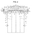
- FIG. 2 is a front view showing another example of the door device for an elevator shown in Fig. 1 .
- each of the first door 5 and the second door 6 has a high-speed door (panel door) 31 and a low-speed door (panel door) 32.
- the low-speed door 32 is displaced with respect to the high-speed door 31 in accordance with the movement of the high-speed door 31.
- Each one of the high-speed doors 31 and the low-speed doors 32 has the door panel 7 and the roller hanger 8.
- a first displacement mechanism 33 for displacing the low-speed door 32 with respect to the high-speed door 31 is provided on the upper portion of the first door 5.
- a second displacement mechanism 34 for displacing the low-speed door 32 with respect to the high-speed door 31 is provided on the upper portion of the second door 6.
- Each of the first displacement mechanism 33 and the second displacement mechanism 34 has a pair of displacement pulleys 35 and 36 provided to both ends of a horizontal bar fixed to the low-speed door 32, and a displacement strip body 37 of an endless type wound between the respective displacement pulleys 35 and 36.
- the high-speed door 31 and the low-speed door 32 are connected to the displacement strip body 37.
- the displacement strip body 37 is orbitally moved through the movement of the high-speed door 31.
- the low-speed door 32 is displaced with respect to the high-speed door 31 oppositely to a moving direction thereof through the orbital movement of the displacement strip body 37. That is, the high-speed door 31 and the low-speed door 32 are connected to the displacement strip body 37 so as to be moved in opposite directions through the orbital movement of the displacement strip body 37.
- Other constructions are identical to those of the foregoing example.
- the respective dimensions of the first power transmission mechanism 17 and the second power transmission mechanism 18 can be reduced even when each of the first door 5 and the second door 6 has the plurality of panel doors. Therefore, an effect similar to that of the foregoing example can be achieved.
- Fig. 3 is a front view showing a door device for an elevator according to Embodiment 2 of the present invention.
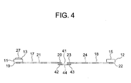
- Fig. 4 is a plan view showing a part of the door device for an elevator of Fig. 3 .
- an interlock mechanism 41 for synchronizing the moving speed of the first door 5 with the moving speed of the second door 6 is provided between the first power transmission mechanism 17 and the second power transmission mechanism 18.
- the interlock mechanism 41 has a first interlock pulley 42 that is rotated integrally with the first driven pulley 20, a second interlock pulley 43 that is rotated integrally with the second driven pulley 23, and an interlock strip body 44 of an endless type wound between the first interlock pulley 42 and the second interlock pulley 43.
- the first interlock pulley 42 is provided coaxially with the first driven pulley 20, and the second interlock pulley 43 is provided coaxially with the second driven pulley 23.
- the interlock strip body 44 is orbitally moved through rotation of the first interlock pulley 42 and rotation of the second interlock pulley 43.
- Employed as the interlock strip body 44 is, for example, a timing belt (cogged belt), or a wire. Other constructions are identical to those of Embodiment 1.
- the interlock mechanism 41 is provided between the first power transmission mechanism 17 and the second power transmission mechanism 18, so the first power transmission mechanism 17 and the second power transmission mechanism 18 can be mechanically interlocked with each other.
- the moving speed of the first door 5 and the moving speed of the second door 6 can be more reliably synchronized with each other.
- the first door driving device 11 and the second door driving device 12 are disposed at both the ends of the car doorway 1 in the direction of the frontage thereof, respectively.
- the position of the first door driving device 11 and the first driving pulley 19 may be changed with the position of the first driven pulley 20
- the position of the second door driving device 12 and the second driving pulley 22 may be changed with the position of the second driven pulley 23.
- the first interlock pulley 42 is provided coaxially with the first driving pulley 19.
- the second interlock pulley 43 is provided coaxially with the second driving pulley 22.
- Fig. 5 is a front view showing a door device for an elevator according to Embodiment 3 of the present invention.
- the encoder 27 for generating a signal according to the rotation of the first rotary shaft 14 is provided as a first position detector to the first door driving device 11.
- An encoder 51 for generating a signal according to the rotation of the second rotary shaft 16 is provided as a second position detector to the second door driving device 12.
- the door control device 28 has a first door control portion 52 for controlling the first door driving device 11 based on the information from the encoder 27, and a second door control portion 53 for controlling the second door driving device 12 based on the information from the encoder 51. That is, the door control device 28 has the first door control portion 52 and the second door control portion 53 which independently control the first door driving device 11 and the second door driving device 12, respectively.
- the car is provided with a car passenger load detecting device 54 for measuring a passenger load within the car.
- a weighing device for measuring the total weight of passengers within the car as a passenger load within the car, an image processing device for measuring the area of a heat source generated by passengers within the car as a passenger load within the car, or the like can be employed as the car passenger load detecting device 54.
- the image processing device In a case where the image processing device is adopted as the car passenger load detecting device 54, temperature distribution within the car at the time when the inside of the car is empty (when there is no passenger on board) is recognized in advance as an image in the image processing device. When a passenger gets on the car, a great change is caused, with respect to the temperature distribution recognized in advance as an image, only in a region corresponding to the passenger being the heat source. Thus, the image processing device measures current temperature distribution within the car, and compares the measured temperature distribution within the car with the temperature distribution recognized in advance as an image to calculate the area of the heat source generated by the passenger.
- a landing is provided with a landing passenger load detecting device 55 for measuring a passenger load at the landing.
- a pressure sensing mat laid within a predetermined region of a floor of the landing e.g., within a region located in front of a landing doorway
- an image processing device for measuring an area of a heat source within a predetermined range in the landing (e.g., within the range of a space located in front of the landing doorway) as a passenger load at the landing in the same manner as the aforementioned image processing device, or the like can be employed as the landing passenger load detecting device 55.
- a car reference value to be compared with the passenger load within the car which is obtained from the car passenger load detecting device 54, and a landing reference value to be compared with the passenger load at the landing which is obtained from the landing passenger load detecting device 55 are set in advance in the door control device 28.
- the door control device 28 controls the first door driving device 11 and the second door driving device 12 to move only one of the first door 5 and the second door 6 when the passenger load within the car is equal to or smaller than the car reference value and the passenger load at the landing is equal to or smaller than the landing reference value.
- the door control device 28 controls the first door driving device 11 and the second door driving device 12 to move both the first door 5 and the second door 6 at least one of when the passenger load within the car is larger than the car reference value and when the passenger load at the landing is larger than the landing reference value.
- the door control device 28 determines whether to move each of the first door 5 and the second door 6 or not in opening/closing the elevator doorway, based on the passenger load within the car and the passenger load at the landing.
- Fig. 6 is a flowchart showing the operation of the door device for an elevator shown in Fig. 5 .
- S1 when the operation of the elevator is activated (the movement of the car is started) (S1), a passenger load ⁇ 1 within the car is measured by the car passenger load detecting device 54 (S2), and information on the passenger load ⁇ 1 within the car is transmitted to the door control device 28.
- a passenger load ⁇ 2 at the landing of a destination floor where a registration of a call for the car has been made is measured by the landing passenger load detecting device 55 (S3), and information on the passenger load ⁇ 2 at the landing is transmitted to the door control device 28.
- the door control device 28 After receiving the passenger load ⁇ 1 within the car and the passenger load ⁇ 2 at the landing, the door control device 28 determines whether or not the passenger load ⁇ 1 within the car is equal to or smaller than a car reference value ⁇ 1 set in advance (S4) .
- the door control device 28 drives both the first door driving device 11 and the second door driving device 12 upon stoppage of the car at the destination floor.
- both the first door 5 and the second door 6 are moved in respective door opening directions (S5).
- the door control device 28 drives both the first door driving device 11 and the second door driving device 12 upon stoppage of the car at the destination floor, as in the case where the passenger load ⁇ 1 within the car is larger than the car reference value ⁇ 1.
- both the first door 5 and the second door 6 are moved in the respective door opening directions (S5) .
- the door control device 28 performs control to drive only one of the first door driving device 11 and the second door driving device 12.
- the door opening direction (S7) only one of the first door 5 and the second door 6 is moved in the door opening direction (S7) .
- the first power transmission mechanism 17 moves the first door 5 in response to the rotation of the first rotary shaft 14, and the second power transmission mechanism 18 moves the second door 6 in response to the rotation of the second rotary shaft 16. Therefore, as in the case of the foregoing Embodiment 1 of the present invention, the first power transmission mechanism 17 and the second power transmission mechanism 18 can be reduced in size, the lives thereof can be prolonged, and the cost of manufacturing can be prevented from increasing.
- the door control device 28 has the first door control portion 52 for controlling the first door driving device 11 and the second door control portion 53 for controlling the second door driving device 12 so as to independently control the first door driving device 11 and the second door driving device 12, respectively. Therefore, the operations of opening/closing the elevator doorway can be performed in accordance with the situation in which the elevator is used.
- the door control device 28 in which the car reference value to be compared with the passenger load within the car is set in advance, moves, based on information from the car passenger load detecting device 54, only one of the first door 5 and the second door 6 when the passenger load within the car is equal to or smaller than the car reference value. Therefore, the operations of opening/closing the elevator doorway can be performed in accordance with the situation of use within the car. Thus, the saving of energy can be achieved.
- the door control device 28 in which the landing reference value to be compared with the passenger load at the landing is set in advance, moves, based on information from the landing passenger load detecting device 55, only one of the first door 5 and the second door 6 when the passenger load at the landing is equal to or smaller than the landing reference value. Therefore, the elevator doorway can be opened/closed in accordance with the situation in which the landing is used. In this manner as well, the saving of energy can be achieved.
- the door control device 28 controls only the movements of the first door 5 and the second door 6 in opening/closing the elevator doorway.
- reporting devices for reporting whether or not each of the first door 5 and the second door 6 is to be moved in opening/closing the elevator doorway may be provided within the car and at the landing, respectively. In this case, the reporting devices are controlled by the door control device 28.
- the reporting devices for example, light emitters provided to a pair of vertical pillars of the elevator doorway, respectively, display devices for displaying characters and charts, or speakers for generating a sound can be employed.
- each of the light emitters which is disposed beside a corresponding one of the doors 5 and 6, emits light only when that door is to be moved in opening/closing the elevator doorway.
- the display devices display the contents of an operation of specifying whether or not each of the doors 5 and 6 is to be moved in opening/closing the elevator doorway.
- the speakers report the contents of an operation thereof as a sound.
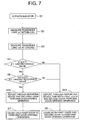
- FIG. 7 is a flowchart showing another example of the operation of the door device for an elevator shown in Fig. 5 .
- the same procedure as in the foregoing example is performed until the passenger load ⁇ 1 within the car and the passenger load ⁇ 2 at the landing are transmitted to the door control device 28 after activation of the elevator.
- the door control device 28 After receiving the passenger load ⁇ 1 within the car and the passenger load ⁇ 2 at the landing, the door control device 28 determines whether or not the passenger load ⁇ 1 within the car is equal to or smaller than the car reference value ⁇ 1 (S4). When the passenger load ⁇ 1 within the car is larger than the car reference value ⁇ 1, the number of users within the car is considered to be large, and the reporting devices report to the inside of the car and the landing that both the first door 5 and the second door 6 are to be moved in the respective door opening directions, upon stoppage of the car at the destination floor (S11).
- the door control device 28 performs control to drive both the first door driving device 11 and the second door driving device 12, so both the first door 5 and the second door 6 are moved in the respective door opening directions (S5).
- the number of users within the car is considered to be small, and it is determined whether or not the passenger load ⁇ 2 at the landing is equal to or smaller than the landing reference value ⁇ 2 (S6) .
- the passenger load ⁇ 2 at the landing is larger than the landing reference value ⁇ 2
- the number of users at the landing is considered to be large, so both the first door 5 and the second door 6 are moved in the respective door opening directions upon stoppage of the car at the destination floor, as in the case where the passenger load ⁇ 1 within the car is larger than the car reference value ⁇ 1 (S5) .
- the reporting devices report to the inside of the car and the landing that one of the first door 5 and the second door 6, for example, only the first door 5, is to be moved in the door opening direction, upon stoppage of the car at the destination floor (S12).
- the door control device 28 performs control to drive, for example, only the first door driving device 11.
- the door control device 28 performs control to drive, for example, only the first door driving device 11.
- the door opening direction (S7) for example, only the first door 5 is moved in the door opening direction (S7).
- both the passenger load ⁇ 1 within the car and the passenger load ⁇ 2 at the landing are measured, and the operations of opening/closing the elevator doorway are performed based on a result of the measurement.
- each of the first door 5 and the second door 6 is designed as a single panel door.
- each of the first door 5 and the second door 6 may have a plurality of panel doors.
Landscapes
- Engineering & Computer Science (AREA)
- Automation & Control Theory (AREA)
- Elevator Door Apparatuses (AREA)
Abstract
Description
- The present invention relates to a door device for an elevator, which serves to open/close an elevator doorway.
- Conventionally, in view for the sake of a reduction in size, a door device for an elevator having an outer-rotor-type motor disposed inside one of a pair of pulleys has been proposed. A belt is wound between the pair of the pulleys. A door for opening/closing a doorway is coupled to the belt. When the one of the pulleys is rotated due to a driving force of the motor, the belt is orbitally moved, so the other pulley is rotated as well. Thus, the door is displaced to open/close the doorway (see Patent Document 1).
- Patent Document 1:
JP 2001-226058 A - However, in the conventional door device for an elevator, the door is displaced due to the driving force of the single motor, so the motor itself is large in size.
Even if the respective pulleys are rotated independently of each other due to driving forces of two motors, a distance between the respective pulleys is increased when, for example, the doorway has a large width. Therefore, tensile force applied to the belt is increased as well. Thus, not only the life of the belt cannot be prolonged, but also the burdens on rotary shafts, bearings, and the like of the respective pulleys are increased. As a result, the motors cannot be substantially reduced in size either. In addition, when the dimension of the belt becomes too long, a standard-sized belt cannot be applied, so a dedicated-sized belt needs to be manufactured. As a result, the cost of manufacturing is increased as well. - The present invention has been made to solve the above-mentionedproblems, and it is therefore an object of the present invention to obtain a door device for an elevator which makes it possible to prevent an increase in cost of manufacturing while achieving a reduction in size and a prolongation of life.
- A door device for an elevator according to the present invention includes: an elevator door having a first door and a second door that are movable in a direction of a frontage of an elevator doorway, for closing the elevator doorway through movements of the first door and the second door into abutment on each other and opening the elevator doorway through movements of the first door and the second door out of abutment on each other; a first door driving device having a first driving device main body and a first rotary shaft that is rotated due to a driving force of the first driving device main body; a first power transmission mechanism to which only the first door of the first door and the second door is coupled, for moving the first door in response to rotation of the first rotary shaft; a second door driving device having a second driving device main body and a second rotary shaft that is rotated due to a driving force of the second driving device main body; a second power transmission mechanism to which only the second door of the first door and the second door is coupled, for moving the second door in response to rotation of the second rotary shaft; a position detector for generating a signal corresponding to the rotation of the first rotary shaft; and a door control device for controlling the second door driving device based on information from the position detector such that the rotation of the second rotary shaft follows the rotation of the first rotary shaft.
-
-
Fig. 1 is a front view showing a door device for an elevator according toEmbodiment 1 of the present invention. -
Fig. 2 is a front view showing another example of the door device for an elevator shown inFig. 1 . -
Fig. 3 is a front view showing a door device for an elevator according toEmbodiment 2 of the present invention. -
Fig. 4 is a plan view showing a part of the door device for an elevator ofFig. 3 . -
Fig. 5 is a front view showing a door device for an elevator according toEmbodiment 3 of the present invention. -
Fig. 6 is a flowchart showing the operation of the door device for an elevator shown inFig. 5 . -
Fig. 7 is a flowchart showing another example of the operation of the door device for an elevator shown inFig. 5 . - Preferred embodiments of the present invention will be described hereinafter with reference to the drawings.
-
Fig. 1 is a front view showing a door device for an elevator according toEmbodiment 1 of the present invention. InFig. 1 , a car (not shown) is provided with a car doorway (elevator doorway) 1. Ahanger case 2, which is provided above thecar doorway 1, is fixed to the car. - A hanger rail (support rail) 3 extending in a direction of a frontage of the
car doorway 1 is fixed to thehanger case 2. Anelevator door 4 for opening/closing thecar doorway 1 is suspended from thehanger rail 3. - The
elevator door 4 has afirst door 5 and asecond door 6, which are movable in the direction of the frontage of thecar doorway 1. Thefirst door 5 and thesecond door 6 are provided side by side in the direction of the frontage of thecar doorway 1. Thecar doorway 1 is closed when thefirst door 5 and thesecond door 6 abut against each other. Thecar doorway 1 is opened when the abutment of thefirst door 5 and thesecond door 6 is released. - The
first door 5 is movable between a first door door-closed position where thefirst door 5 can abut against thesecond door 6, and a first door door-open position located on a door opening side (a side in which thecar doorway 1 is opened) with respect to the first door door-closed position. Thesecond door 6 is movable between a second door door-closed position where thesecond door 6 can abut against thefirst door 5, and a second door door-open position located on a door opening side (a side in which thecar doorway 1 is opened) with respect to the second door door-closed position. - The
car doorway 1 is fully closed when thefirst door 5 is at the first door door-closed position and thesecond door 6 is at the second door door-closed position. Thecar doorway 1 is fully opened when thefirst door 5 is at the first door door-open position and thesecond door 6 is at the second door door-open position. - Each of the
first door 5 and thesecond door 6 is also designed as a panel door having adoor panel 7, which is used to open/close thecar doorway 1, and aroller hanger 8, which is provided on an upper portion of thedoor panel 7, and can move along thehanger rail 3. - Each of the
hanger rollers 8 has ahanger plate 9 fixed to the upper portion of one of thedoor panels 7, and a plurality ofrollers 10 provided to thehanger plate 9 to be rolled on thehanger rail 3 in accordance with the movement of each one of thefirst door 5 and thesecond door 6. - The
hanger case 2 is provided with a firstdoor driving device 11 and a seconddoor driving device 12, which are disposed apart from each other in the direction of the frontage of thecar doorway 1. In this example, the firstdoor driving device 11 is provided to one end of thehanger case 2, and the seconddoor driving device 12 is provided to the other end of thehanger case 2. - The first
door driving device 11 has a first driving devicemain body 13 including a motor, and a firstrotary shaft 14 that is rotated due to a driving force of the first driving devicemain body 13. The seconddoor driving device 12 has a second driving devicemain body 15 including a motor, and a secondrotary shaft 16 that is rotated due to a driving force of the second driving devicemain body 15. - In addition, the
hanger case 2 is provided with a firstpower transmission mechanism 17 for moving thefirst door 5 in response to rotation of the firstrotary shaft 14, and a secondpower transmission mechanism 18 for moving thesecond door 6 in response to rotation of the secondrotary shaft 16. The firstpower transmission mechanism 17 and the secondpower transmission mechanism 18 are disposed side by side in the direction of the frontage of thecar doorway 1. - The first
power transmission mechanism 17 has afirst driving pulley 19 fixed to the firstrotary shaft 14, a first drivenpulley 20 provided to an inner side than thefirst driving pulley 19 in the direction of the frontage of thecar doorway 1, and a firsttransmission strip body 21 of an endless type wound between thefirst driving pulley 19 and the first drivenpulley 20. - The first
transmission strip body 21 is orbitally moved through rotation of thefirst driving pulley 19. The first drivenpulley 20 is rotated through the orbital movement of the firsttransmission strip body 21. - The
first door 5 is coupled to the firsttransmission strip body 21 via acoupling member 25 so as to be moved in the direction of the frontage of thecar doorway 1 through the orbital movement of the firsttransmission strip body 21. Thus, thefirst door 5 is moved between the first door door-open position and the first door door-closed position in accordance with the rotation of thefirst driving pulley 19. - The second
power transmission mechanism 18 has asecond driving pulley 22 fixed to the secondrotary shaft 16, a second drivenpulley 23 provided to an inner side than thesecond driving pulley 22 in the direction of the frontage of thecar doorway 1, and a secondtransmission strip body 24 of an endless type wound between thesecond driving pulley 22 and the second drivenpulley 23. - The second
transmission strip body 24 is orbitally moved through rotation of thesecond driving pulley 22. The second drivenpulley 23 is rotated through the orbital movement of the secondtransmission strip body 24. - The
second door 6 is coupled to the secondtransmission strip body 24 via acoupling member 26 so as to be moved in the direction of the frontage of thecar doorway 1 through the orbital movement of the secondtransmission strip body 24. Thus, thesecond door 6 is moved between the second door door-open position and the second door door-closed position in accordance with rotation of thesecond driving pulley 22. Examples of the firsttransmission strip body 21 and the secondtransmission strip body 24 include timing belts (synchronous belts), wires, or the like. - That is, of the
first door 5 and thesecond door 6, only thefirst door 5 is coupled to the firstpower transmission mechanism 17, and only thesecond door 6 is coupled to the secondpower transmission mechanism 18. In addition, in the direction of the frontage of thecar doorway 1, the firstpower transmission mechanism 17 has a minimum required dimension for moving thefirst door 5 between the first door door-closed position and the first door door-open position. Further, in the direction of the frontage of thecar doorway 1, the secondpower transmission mechanism 18 has a minimum required dimension for moving thesecond door 6 between the second door door-closed position and the second door door-open position. - The first
door driving device 11 is provided with an encoder (position detector) 27 for generating a signal (pulse signal) corresponding to the rotation of the firstrotary shaft 14. The car is mounted with adoor control device 28 for controlling the firstdoor driving device 11 and the seconddoor driving device 12. When an opening/closing command is input from an operation control device (not shown) installed within a hoistway, thedoor control device 28 drives the firstdoor driving device 11 and the seconddoor driving device 12 to open/close thecar doorway 1. - The
door control device 28 controls the firstdoor driving device 11 based on the opening/closing command from the operation control device. Thus, the rotation of the firstrotary shaft 14 is controlled by thedoor control device 28. Thedoor control device 28 also controls the seconddoor driving device 12 based on information from theencoder 27, such that the rotation of the secondrotary shaft 16 follows the rotation of the firstrotary shaft 14. Thus, thefirst door 5 and thesecond door 6 are moved in opposite directions in synchronization with each other. - Note that the
door control device 28 is constituted by a computer having a calculation processing portion (CPU), a storage portion (ROM, RAM, or the like), and a signal input/output portion. The function of thedoor control device 28 is realized by the computer constituting thedoor control device 28. - Next, an operation will be described. A signal corresponding to the rotation of the first
rotary shaft 14 is transmitted from theencoder 27 to thedoor control device 28. When an opening/closing command from the operation control device is input to thedoor control device 28, thedoor control device 28 performs control to drive the firstdoor driving device 11 and the seconddoor driving device 12. At this moment, the rotation of the secondrotary shaft 16 is controlled by thedoor control device 28 based on information from theencoder 27. Thus, the secondrotary shaft 16 is rotated in accordance with the rotation of the firstrotary shaft 14. - When the first
rotary shaft 14 is rotated, the firsttransmission strip body 21 is orbitally moved. Thus, thefirst door 5 is moved in the direction of the frontage of thecar doorway 1. In addition, when the secondrotary shaft 16 is rotated, the secondtransmission strip body 24 is orbitally moved. Thus, thesecond door 6 is moved in the direction of the frontage of the car doorway - 1. The second
rotary shaft 16 is rotated in accordance with the rotation of the firstrotary shaft 14, so thefirst door 5 and thesecond door 6 are moved in synchronization with each other. As a result, thecar doorway 1 is opened/closed. - In the door device for an elevator as described above, the first
power transmission mechanism 17 moves thefirst door 5 in response to the rotation of the firstrotary shaft 14, and the secondpower transmission mechanism 18 moves thesecond door 6 in response to the rotation of the secondrotary shaft 16. Therefore, the firstpower transmission mechanism 17 and thesecond power transmissionmechanism 18 can be disposed side by side in the direction of the frontage of thecar doorway 1, and the respective dimensions of the firstpower transmission mechanism 17 and the secondpower transmission mechanism 18 can be reduced with respect to the dimension of the frontage of thecar doorway 1. Thus, the lengths of the firsttransmission strip body 21 and the secondtransmission strip body 24 can be reduced when the firsttransmission strip body 21 and the secondtransmission strip body 24 are designed to be moved together with thefirst door 5 and thesecond door 6 in the firstpower transmission mechanism 17 and the secondpower transmission mechanism 18, respectively. As the firsttransmission strip body 21 and the secondtransmission strip body 24 standard components can be employed even when the dimension of the frontage of thecar doorway 1 is too large. In consequence, the cost of manufacturing can be prevented from increasing. - In addition, the lengths of the first
transmission strip body 21 and the secondtransmission strip body 24 can be reduced, so the tensile forces applied to the firsttransmission strip body 21 and the secondtransmission strip body 24 can be reduced as well. Thus, the lives of the firsttransmission strip body 21 and the secondtransmission strip body 24 can be prolonged, and the firstdoor driving device 11 and the seconddoor driving device 12, which receive the tensile forces applied to the firsttransmission strip body 21 and the secondtransmission strip body 24, respectively, can be reduced in size as well. - Further, the second
rotary shaft 16 is controlled by thedoor control device 28 so as to be rotated in accordance with the rotation of the firstrotary shaft 14, so thefirst door 5 and thesecond door 6 can be moved in synchronization with each other. In addition, there is no need to provide the seconddoor driving device 12 with an encoder for measuring the rotation of the secondrotary shaft 16, so the number of components can be reduced. As a result, the cost of manufacturing can further be reduced. - Note that in the foregoing example, each of the
first door 5 and thesecond door 6 is assumed to be a single panel door. However, each of thefirst door 5 and thesecond door 6 may have a plurality of panel doors. - That is,
Fig. 2 is a front view showing another example of the door device for an elevator shown inFig. 1 . InFig. 2 , each of thefirst door 5 and thesecond door 6 has a high-speed door (panel door) 31 and a low-speed door (panel door) 32. The low-speed door 32 is displaced with respect to the high-speed door 31 in accordance with the movement of the high-speed door 31. Each one of the high-speed doors 31 and the low-speed doors 32 has thedoor panel 7 and theroller hanger 8. - A
first displacement mechanism 33 for displacing the low-speed door 32 with respect to the high-speed door 31 is provided on the upper portion of thefirst door 5. Asecond displacement mechanism 34 for displacing the low-speed door 32 with respect to the high-speed door 31 is provided on the upper portion of thesecond door 6. - Each of the
first displacement mechanism 33 and thesecond displacement mechanism 34 has a pair of displacement pulleys 35 and 36 provided to both ends of a horizontal bar fixed to the low-speed door 32, and adisplacement strip body 37 of an endless type wound between the respective displacement pulleys 35 and 36. - The high-
speed door 31 and the low-speed door 32 are connected to thedisplacement strip body 37. Thedisplacement strip body 37 is orbitally moved through the movement of the high-speed door 31. The low-speed door 32 is displaced with respect to the high-speed door 31 oppositely to a moving direction thereof through the orbital movement of thedisplacement strip body 37. That is, the high-speed door 31 and the low-speed door 32 are connected to thedisplacement strip body 37 so as to be moved in opposite directions through the orbital movement of thedisplacement strip body 37. Other constructions are identical to those of the foregoing example. - As described above, the respective dimensions of the first
power transmission mechanism 17 and the secondpower transmission mechanism 18 can be reduced even when each of thefirst door 5 and thesecond door 6 has the plurality of panel doors. Therefore, an effect similar to that of the foregoing example can be achieved. -
Fig. 3 is a front view showing a door device for an elevator according toEmbodiment 2 of the present invention. In addition,Fig. 4 is a plan view showing a part of the door device for an elevator ofFig. 3 . In the figures, aninterlock mechanism 41 for synchronizing the moving speed of thefirst door 5 with the moving speed of thesecond door 6 is provided between the firstpower transmission mechanism 17 and the secondpower transmission mechanism 18. - The
interlock mechanism 41 has afirst interlock pulley 42 that is rotated integrally with the first drivenpulley 20, asecond interlock pulley 43 that is rotated integrally with the second drivenpulley 23, and aninterlock strip body 44 of an endless type wound between thefirst interlock pulley 42 and thesecond interlock pulley 43. - The
first interlock pulley 42 is provided coaxially with the first drivenpulley 20, and thesecond interlock pulley 43 is provided coaxially with the second drivenpulley 23. Theinterlock strip body 44 is orbitally moved through rotation of thefirst interlock pulley 42 and rotation of thesecond interlock pulley 43. Employed as theinterlock strip body 44 is, for example, a timing belt (cogged belt), or a wire. Other constructions are identical to those ofEmbodiment 1. - In the door device for an elevator constructed as described above, the
interlock mechanism 41 is provided between the firstpower transmission mechanism 17 and the secondpower transmission mechanism 18, so the firstpower transmission mechanism 17 and the secondpower transmission mechanism 18 can be mechanically interlocked with each other. As a result, the moving speed of thefirst door 5 and the moving speed of thesecond door 6 can be more reliably synchronized with each other. - Note that in each of the foregoing examples, the first
door driving device 11 and the seconddoor driving device 12 are disposed at both the ends of thecar doorway 1 in the direction of the frontage thereof, respectively. However, the position of the firstdoor driving device 11 and the first drivingpulley 19 may be changed with the position of the first drivenpulley 20, and the position of the seconddoor driving device 12 and the second drivingpulley 22 may be changed with the position of the second drivenpulley 23. In the case where the position of the firstdoor driving device 11 is changed, thefirst interlock pulley 42 is provided coaxially with the first drivingpulley 19. In the case where the position of the seconddoor driving device 12 is changed, thesecond interlock pulley 43 is provided coaxially with the second drivingpulley 22. -
Fig. 5 is a front view showing a door device for an elevator according toEmbodiment 3 of the present invention. InFig. 5 , theencoder 27 for generating a signal according to the rotation of the firstrotary shaft 14 is provided as a first position detector to the firstdoor driving device 11. Anencoder 51 for generating a signal according to the rotation of the secondrotary shaft 16 is provided as a second position detector to the seconddoor driving device 12. - Information from the
encoder 27 and information from theencoder 51 are input to thedoor control device 28. Thedoor control device 28 has a firstdoor control portion 52 for controlling the firstdoor driving device 11 based on the information from theencoder 27, and a seconddoor control portion 53 for controlling the seconddoor driving device 12 based on the information from theencoder 51. That is, thedoor control device 28 has the firstdoor control portion 52 and the seconddoor control portion 53 which independently control the firstdoor driving device 11 and the seconddoor driving device 12, respectively. - The car is provided with a car passenger
load detecting device 54 for measuring a passenger load within the car. A weighing device for measuring the total weight of passengers within the car as a passenger load within the car, an image processing device for measuring the area of a heat source generated by passengers within the car as a passenger load within the car, or the like can be employed as the car passengerload detecting device 54. - In a case where the image processing device is adopted as the car passenger
load detecting device 54, temperature distribution within the car at the time when the inside of the car is empty (when there is no passenger on board) is recognized in advance as an image in the image processing device. When a passenger gets on the car, a great change is caused, with respect to the temperature distribution recognized in advance as an image, only in a region corresponding to the passenger being the heat source. Thus, the image processing device measures current temperature distribution within the car, and compares the measured temperature distribution within the car with the temperature distribution recognized in advance as an image to calculate the area of the heat source generated by the passenger. - A landing is provided with a landing passenger
load detecting device 55 for measuring a passenger load at the landing. A pressure sensing mat laid within a predetermined region of a floor of the landing (e.g., within a region located in front of a landing doorway) to measure a quantity corresponding to a pressure sensed upon the boarding of passengers as a passenger load at the landing, an image processing device for measuring an area of a heat source within a predetermined range in the landing (e.g., within the range of a space located in front of the landing doorway) as a passenger load at the landing in the same manner as the aforementioned image processing device, or the like can be employed as the landing passengerload detecting device 55. - A car reference value to be compared with the passenger load within the car which is obtained from the car passenger
load detecting device 54, and a landing reference value to be compared with the passenger load at the landing which is obtained from the landing passengerload detecting device 55 are set in advance in thedoor control device 28. - In addition, the
door control device 28 controls the firstdoor driving device 11 and the seconddoor driving device 12 to move only one of thefirst door 5 and thesecond door 6 when the passenger load within the car is equal to or smaller than the car reference value and the passenger load at the landing is equal to or smaller than the landing reference value. Thedoor control device 28 controls the firstdoor driving device 11 and the seconddoor driving device 12 to move both thefirst door 5 and thesecond door 6 at least one of when the passenger load within the car is larger than the car reference value and when the passenger load at the landing is larger than the landing reference value. - That is, the
door control device 28 determines whether to move each of thefirst door 5 and thesecond door 6 or not in opening/closing the elevator doorway, based on the passenger load within the car and the passenger load at the landing. - Next, an operation will be described.
Fig. 6 is a flowchart showing the operation of the door device for an elevator shown inFig. 5 . As shown inFig. 6 , when the operation of the elevator is activated (the movement of the car is started) (S1), a passenger load α1 within the car is measured by the car passenger load detecting device 54 (S2), and information on the passenger load α1 within the car is transmitted to thedoor control device 28. A passenger load α2 at the landing of a destination floor where a registration of a call for the car has been made is measured by the landing passenger load detecting device 55 (S3), and information on the passenger load α2 at the landing is transmitted to thedoor control device 28. - After receiving the passenger load α1 within the car and the passenger load α2 at the landing, the
door control device 28 determines whether or not the passenger load α1 within the car is equal to or smaller than a car reference value β1 set in advance (S4) . When the passenger load α1 within the car is larger than the car reference value β1, the number of users within the car is considered to be large, so thedoor control device 28 drives both the firstdoor driving device 11 and the seconddoor driving device 12 upon stoppage of the car at the destination floor. Thus, both thefirst door 5 and thesecond door 6 are moved in respective door opening directions (S5). - When the passenger load α1 within the car is equal to or smaller than the car reference value β1, in the
door control device 28, the number of users within the car is considered to be small, and it is determined whether or not the passenger load α2 at the landing is equal to or smaller than a landing reference value β2 set in advance (S6). When the passenger load α2 at the landing is larger than the landing reference value β2, the number of users at the landing is considered to be large, so thedoor control device 28 drives both the firstdoor driving device 11 and the seconddoor driving device 12 upon stoppage of the car at the destination floor, as in the case where the passenger load α1 within the car is larger than the car reference value β1. Thus, both thefirst door 5 and thesecond door 6 are moved in the respective door opening directions (S5) . - When the passenger load α2 at the landing is equal to or smaller than the landing reference value β2, not only the number of users within the car but also the number of users at the landing are considered to be small, so the
door control device 28 performs control to drive only one of the firstdoor driving device 11 and the seconddoor driving device 12. Thus, only one of thefirst door 5 and thesecond door 6 is moved in the door opening direction (S7) . - In the door device for an elevator constructed as described above as well, the first
power transmission mechanism 17 moves thefirst door 5 in response to the rotation of the firstrotary shaft 14, and the secondpower transmission mechanism 18 moves thesecond door 6 in response to the rotation of the secondrotary shaft 16. Therefore, as in the case of the foregoingEmbodiment 1 of the present invention, the firstpower transmission mechanism 17 and the secondpower transmission mechanism 18 can be reduced in size, the lives thereof can be prolonged, and the cost of manufacturing can be prevented from increasing. - In addition, the
door control device 28 has the firstdoor control portion 52 for controlling the firstdoor driving device 11 and the seconddoor control portion 53 for controlling the seconddoor driving device 12 so as to independently control the firstdoor driving device 11 and the seconddoor driving device 12, respectively. Therefore, the operations of opening/closing the elevator doorway can be performed in accordance with the situation in which the elevator is used. - For example, in an office building or the like, a large number of users flock to an elevator at clock-in time in the morning, at clock-out time in the evening, and at lunchtime. The time zones in which a large number of users flock to the elevator are limited, and the number of users of the elevator may be small during off-peak periods other than the above-mentioned time zones. Considering the installation of an elevator, however, the width of an elevator doorway is determined on the basis of the peak number of users of the elevator, so the elevator is designed to have an exaggerated specification for the number of users during the off-peak periods. Accordingly, when, for example, the number of passengers getting on and off the car is small and there is hence no need to fully open the elevator doorway during a door opening operation, only one of the
first door 5 and thesecond door 6 can be moved in the door opening direction. Therefore, the amount of energy consumption can be reduced, and the saving of energy can be achieved. - The
door control device 28, in which the car reference value to be compared with the passenger load within the car is set in advance, moves, based on information from the car passengerload detecting device 54, only one of thefirst door 5 and thesecond door 6 when the passenger load within the car is equal to or smaller than the car reference value. Therefore, the operations of opening/closing the elevator doorway can be performed in accordance with the situation of use within the car. Thus, the saving of energy can be achieved. - The
door control device 28, in which the landing reference value to be compared with the passenger load at the landing is set in advance, moves, based on information from the landing passengerload detecting device 55, only one of thefirst door 5 and thesecond door 6 when the passenger load at the landing is equal to or smaller than the landing reference value. Therefore, the elevator doorway can be opened/closed in accordance with the situation in which the landing is used. In this manner as well, the saving of energy can be achieved. - In each of the foregoing examples, the
door control device 28 controls only the movements of thefirst door 5 and thesecond door 6 in opening/closing the elevator doorway. However, reporting devices for reporting whether or not each of thefirst door 5 and thesecond door 6 is to be moved in opening/closing the elevator doorway may be provided within the car and at the landing, respectively. In this case, the reporting devices are controlled by thedoor control device 28. As the reporting devices, for example, light emitters provided to a pair of vertical pillars of the elevator doorway, respectively, display devices for displaying characters and charts, or speakers for generating a sound can be employed. - In the case where the light emitters are adopted as the reporting devices, each of the light emitters, which is disposed beside a corresponding one of the
doors doors - That is,
Fig. 7 is a flowchart showing another example of the operation of the door device for an elevator shown inFig. 5 . As shown inFig. 7 , the same procedure as in the foregoing example is performed until the passenger load α1 within the car and the passenger load α2 at the landing are transmitted to thedoor control device 28 after activation of the elevator. - After receiving the passenger load α1 within the car and the passenger load α2 at the landing, the
door control device 28 determines whether or not the passenger load α1 within the car is equal to or smaller than the car reference value β1 (S4). When the passenger load α1 within the car is larger than the car reference value β1, the number of users within the car is considered to be large, and the reporting devices report to the inside of the car and the landing that both thefirst door 5 and thesecond door 6 are to be moved in the respective door opening directions, upon stoppage of the car at the destination floor (S11). - After that, the
door control device 28 performs control to drive both the firstdoor driving device 11 and the seconddoor driving device 12, so both thefirst door 5 and thesecond door 6 are moved in the respective door opening directions (S5). - When the passenger load α1 within the car is equal to or smaller than the car reference value β1, in the
door control device 28, the number of users within the car is considered to be small, and it is determined whether or not the passenger load α2 at the landing is equal to or smaller than the landing reference value β2 (S6) . When the passenger load α2 at the landing is larger than the landing reference value β2, the number of users at the landing is considered to be large, so both thefirst door 5 and thesecond door 6 are moved in the respective door opening directions upon stoppage of the car at the destination floor, as in the case where the passenger load α1 within the car is larger than the car reference value β1 (S5) . - When the passenger load α2 at the landing is equal to or smaller than the landing reference value β2, not only the number of users within the car but also the number of users at the landing are considered to be small, so the reporting devices report to the inside of the car and the landing that one of the
first door 5 and thesecond door 6, for example, only thefirst door 5, is to be moved in the door opening direction, upon stoppage of the car at the destination floor (S12). - After that, the
door control device 28 performs control to drive, for example, only the firstdoor driving device 11. Thus, for example, only thefirst door 5 is moved in the door opening direction (S7). - In this manner, a passenger can realize in advance whether or not each of the door or doors to be moved when the elevator doorway is opened/closed. As a result, the passengers are allowed to get on and off the car smoothly.
- In each of the foregoing examples, both the passenger load α1 within the car and the passenger load α2 at the landing are measured, and the operations of opening/closing the elevator doorway are performed based on a result of the measurement. However, it is also appropriate to measure only one of the passenger load α1 within the car and the passenger load α2 at the landing, and to perform the operations of opening/closing the elevator doorway based on a result of the measurement.
- In each of
Embodiments first door 5 and thesecond door 6 is designed as a single panel door. However, each of thefirst door 5 and thesecond door 6 may have a plurality of panel doors.
Claims (7)
- A door device for an elevator, comprising:an elevator door having a first door and a second door that are movable in a direction of a frontage of an elevator doorway, for closing the elevator doorway through movements of the first door and the second door into abutment on each other and opening the elevator doorway through movements of the first door and the second door out of abutment on each other;a first door driving device having a first driving device main body and a first rotary shaft that is rotated due to a driving force of the first driving device main body;a first power transmission mechanism to which only the first door of the first door and the second door is coupled, for moving the first door in response to rotation of the first rotary shaft;a second door driving device having a second driving device main body and a second rotary shaft that is rotated due to a driving force of the second driving device main body;a second power transmission mechanism to which only the second door of the first door and the second door is coupled, for moving the second door in response to rotation of the second rotary shaft;a position detector for generating a signal corresponding to the rotation of the first rotary shaft; anda door control device for controlling the second door driving device based on information from the position detector such that the rotation of the second rotary shaft follows the rotation of the first rotary shaft.
- A door device for an elevator according to Claim 1, wherein the first power transmission mechanism and the second power transmission mechanism have provided therebetween an interlock mechanism for synchronizing a moving speed of the first door and a moving speed of the second door with each other.
- A door device for an elevator, comprising:an elevator door having a first door and a second door that are movable in a direction of a frontage of an elevator doorway, for closing the elevator doorway through movements of the first door and the second door into abutment on each other and opening the elevator doorway through movements of the first door and the second door out of abutment on each other;a first door driving device having a first driving device main body and a first rotary shaft that is rotated due to a driving force of the first driving device main body;a first power transmission mechanism to which only the first door of the first door and the second door is coupled, for moving the first door in response to rotation of the first rotary shaft;a second door driving device having a second driving device main body and a second rotary shaft that is rotated due to a driving force of the second driving device main body;a second power transmission mechanism to which only the second door of the first door and the second door is coupled, for moving the second door in response to rotation of the second rotary shaft;a first position detector for generating a signal corresponding to the rotation of the first rotary shaft;a second position detector for generating a signal corresponding to the rotation of the second rotary shaft; anda door control device having a first door control portion for controlling the first door driving device based on information from the first position detector, and a second door control portion for controlling the second door driving device based on information from the second position detector, for controlling the first door driving device and the second door driving device independently of each other.
- A door device for an elevator according to Claim 3, further comprising a car passenger load detecting device for measuring a passenger load within a car,
wherein the door control device controls the first door driving device and the second door driving device to move only one of the first door and the second door when the passenger load is equal to or smaller than a car reference value set in advance. - A door device for an elevator according to Claim 3, further comprising a landing passenger load detecting device for measuring a passenger load at a landing,
wherein the door control device controls the first door driving device and the second door driving device to move only one of the first door and the second door when the passenger load is equal to or smaller than a landing reference value set in advance. - A door device for an elevator according to Claim 4 or 5, further comprising a reporting device for reporting, based on information from the door control device, to an inside of the car or the landing whether or not each of the first door and the second door is to be moved in opening/closing the elevator doorway.
- A door device for an elevator according to any one of Claims 1 to 6, wherein each of the first door and the second door has a high-speed door and a low-speed door that is displaced with respect to the high-speed door in accordance with a movement of the high-speed door.
Applications Claiming Priority (1)
| Application Number | Priority Date | Filing Date | Title |
|---|---|---|---|
| PCT/JP2005/019303 WO2007046149A1 (en) | 2005-10-20 | 2005-10-20 | Door device for elevator |
Publications (2)
| Publication Number | Publication Date |
|---|---|
| EP1939126A1 true EP1939126A1 (en) | 2008-07-02 |
| EP1939126A4 EP1939126A4 (en) | 2012-09-26 |
Family
ID=37962251
Family Applications (1)
| Application Number | Title | Priority Date | Filing Date |
|---|---|---|---|
| EP05795845A Withdrawn EP1939126A4 (en) | 2005-10-20 | 2005-10-20 | DOOR DEVICE FOR ELEVATOR |
Country Status (5)
| Country | Link |
|---|---|
| EP (1) | EP1939126A4 (en) |
| JP (1) | JP5042628B2 (en) |
| KR (1) | KR100960434B1 (en) |
| CN (1) | CN101146734B (en) |
| WO (1) | WO2007046149A1 (en) |
Cited By (1)
| Publication number | Priority date | Publication date | Assignee | Title |
|---|---|---|---|---|
| US10472211B2 (en) | 2017-05-24 | 2019-11-12 | Otis Elevator Company | People conveyor |
Families Citing this family (4)
| Publication number | Priority date | Publication date | Assignee | Title |
|---|---|---|---|---|
| KR101111163B1 (en) * | 2011-07-19 | 2012-02-24 | 세화정공 주식회사 | Car door automatic switchgear installed within the width of elevator doorway |
| JP6335595B2 (en) * | 2014-04-07 | 2018-05-30 | 三菱電機株式会社 | elevator |
| CN104444735B (en) * | 2014-10-13 | 2017-01-18 | 上海富士电梯有限公司 | Two-way regulation and control type elevator door opening system |
| CN110467097A (en) * | 2019-08-17 | 2019-11-19 | 成都红旗油脂有限公司 | A kind of lift car |
Family Cites Families (10)
| Publication number | Priority date | Publication date | Assignee | Title |
|---|---|---|---|---|
| JPS5639282A (en) * | 1979-09-04 | 1981-04-14 | Mitsubishi Electric Corp | Central double sliding door unit for elevator |
| JPS6052998B2 (en) * | 1980-01-21 | 1985-11-22 | 三菱電機株式会社 | Elevator center double sliding door device |
| JPS5767490A (en) * | 1980-10-16 | 1982-04-24 | Mitsubishi Electric Corp | Controller for opening of door of elevator |
| JPS5820277U (en) * | 1981-07-29 | 1983-02-08 | フジテック株式会社 | Elevator door control device |
| JPS5820277A (en) * | 1981-07-29 | 1983-02-05 | ヤンマー農機株式会社 | Oscillating sorter |
| JPS61142774A (en) * | 1984-12-15 | 1986-06-30 | Matsushita Electric Works Ltd | Mos transistor |
| JPS61142774U (en) * | 1985-02-25 | 1986-09-03 | ||
| EP0841285A1 (en) * | 1996-11-07 | 1998-05-13 | Otis Elevator Company | Elevator car door system |
| JP2003026381A (en) * | 2001-07-12 | 2003-01-29 | Hitachi Building Systems Co Ltd | Elevator doorway devices |
| US6943508B2 (en) * | 2002-09-23 | 2005-09-13 | Otis Elevator Company | Tubular linear synchronous motor control for elevator doors |
-
2005
- 2005-10-20 CN CN2005800493239A patent/CN101146734B/en not_active Expired - Fee Related
- 2005-10-20 EP EP05795845A patent/EP1939126A4/en not_active Withdrawn
- 2005-10-20 WO PCT/JP2005/019303 patent/WO2007046149A1/en not_active Ceased
- 2005-10-20 KR KR1020077020668A patent/KR100960434B1/en not_active Expired - Fee Related
- 2005-10-20 JP JP2006538576A patent/JP5042628B2/en not_active Expired - Fee Related
Cited By (1)
| Publication number | Priority date | Publication date | Assignee | Title |
|---|---|---|---|---|
| US10472211B2 (en) | 2017-05-24 | 2019-11-12 | Otis Elevator Company | People conveyor |
Also Published As
| Publication number | Publication date |
|---|---|
| CN101146734B (en) | 2011-08-10 |
| KR100960434B1 (en) | 2010-05-28 |
| JPWO2007046149A1 (en) | 2009-04-23 |
| EP1939126A4 (en) | 2012-09-26 |
| JP5042628B2 (en) | 2012-10-03 |
| KR20070106766A (en) | 2007-11-05 |
| CN101146734A (en) | 2008-03-19 |
| WO2007046149A1 (en) | 2007-04-26 |
Similar Documents
| Publication | Publication Date | Title |
|---|---|---|
| US5125481A (en) | Diagonal elevation apparatus | |
| US10829989B2 (en) | Motor-operable and vertically movable gate | |
| JP5044102B2 (en) | A device for accurately positioning each cage of an elevator multistage cage | |
| EP1939126A1 (en) | Door device for elevator | |
| ZA200709083B (en) | Lift with two lift cages disposed one above the other in a lift shaft | |
| CN105026299A (en) | Elevator door control device | |
| JP2009249155A (en) | Door opening and closing device of elevator | |
| WO1998021139A1 (en) | Elevator cab | |
| JP5554369B2 (en) | Elevator hall door device and its opening / closing device | |
| US11661778B2 (en) | High speed overhead door | |
| JP5078432B2 (en) | Elevator hall door device and its opening / closing device | |
| CN1964910A (en) | Elevator door device | |
| KR900004973Y1 (en) | Detection system of position of elevator | |
| JP2011102164A (en) | Elevator device and door device for elevator | |
| EP1932796A1 (en) | Door device for elevator | |
| JP2008001521A (en) | Elevator sill equipment | |
| ES8609151A1 (en) | Lift door actuating device. | |
| JP2504275B2 (en) | Elevator door device | |
| US20060180404A1 (en) | Elevator installation with hoistway door and door-closing device | |
| JP4567347B2 (en) | Elevator door control device | |
| JP7153250B1 (en) | elevator | |
| EP0776860A2 (en) | Car operated safety gate for horizontally transferable elevator cab | |
| JP2003192249A (en) | Household elevator | |
| KR100351281B1 (en) | Gate open/close apparatus | |
| JPH0494392A (en) | Door device of elevator |
Legal Events
| Date | Code | Title | Description |
|---|---|---|---|
| PUAI | Public reference made under article 153(3) epc to a published international application that has entered the european phase |
Free format text: ORIGINAL CODE: 0009012 |
|
| 17P | Request for examination filed |
Effective date: 20070822 |
|
| AK | Designated contracting states |
Kind code of ref document: A1 Designated state(s): DE |
|
| RBV | Designated contracting states (corrected) |
Designated state(s): DE |
|
| DAX | Request for extension of the european patent (deleted) | ||
| A4 | Supplementary search report drawn up and despatched |
Effective date: 20120827 |
|
| RIC1 | Information provided on ipc code assigned before grant |
Ipc: B66B 13/14 20060101AFI20120821BHEP Ipc: B66B 13/08 20060101ALI20120821BHEP Ipc: B66B 3/00 20060101ALI20120821BHEP |
|
| STAA | Information on the status of an ep patent application or granted ep patent |
Free format text: STATUS: THE APPLICATION HAS BEEN WITHDRAWN |
|
| 18W | Application withdrawn |
Effective date: 20140211 |