EP1938862A2 - System und Verfahren zum Umgang mit Atemstörungen - Google Patents
System und Verfahren zum Umgang mit Atemstörungen Download PDFInfo
- Publication number
- EP1938862A2 EP1938862A2 EP08006191A EP08006191A EP1938862A2 EP 1938862 A2 EP1938862 A2 EP 1938862A2 EP 08006191 A EP08006191 A EP 08006191A EP 08006191 A EP08006191 A EP 08006191A EP 1938862 A2 EP1938862 A2 EP 1938862A2
- Authority
- EP
- European Patent Office
- Prior art keywords
- disordered breathing
- patient
- sleep
- therapy
- pacing
- Prior art date
- Legal status (The legal status is an assumption and is not a legal conclusion. Google has not performed a legal analysis and makes no representation as to the accuracy of the status listed.)
- Granted
Links
Images


Classifications
-
- A—HUMAN NECESSITIES
- A61—MEDICAL OR VETERINARY SCIENCE; HYGIENE
- A61B—DIAGNOSIS; SURGERY; IDENTIFICATION
- A61B5/00—Measuring for diagnostic purposes; Identification of persons
- A61B5/48—Other medical applications
- A61B5/4806—Sleep evaluation
- A61B5/4818—Sleep apnoea
-
- A—HUMAN NECESSITIES
- A61—MEDICAL OR VETERINARY SCIENCE; HYGIENE
- A61B—DIAGNOSIS; SURGERY; IDENTIFICATION
- A61B5/00—Measuring for diagnostic purposes; Identification of persons
- A61B5/0002—Remote monitoring of patients using telemetry, e.g. transmission of vital signals via a communication network
- A61B5/0031—Implanted circuitry
-
- A—HUMAN NECESSITIES
- A61—MEDICAL OR VETERINARY SCIENCE; HYGIENE
- A61B—DIAGNOSIS; SURGERY; IDENTIFICATION
- A61B5/00—Measuring for diagnostic purposes; Identification of persons
- A61B5/02—Detecting, measuring or recording for evaluating the cardiovascular system, e.g. pulse, heart rate, blood pressure or blood flow
- A61B5/0205—Simultaneously evaluating both cardiovascular conditions and different types of body conditions, e.g. heart and respiratory condition
- A61B5/02055—Simultaneously evaluating both cardiovascular condition and temperature
-
- A—HUMAN NECESSITIES
- A61—MEDICAL OR VETERINARY SCIENCE; HYGIENE
- A61B—DIAGNOSIS; SURGERY; IDENTIFICATION
- A61B5/00—Measuring for diagnostic purposes; Identification of persons
- A61B5/02—Detecting, measuring or recording for evaluating the cardiovascular system, e.g. pulse, heart rate, blood pressure or blood flow
- A61B5/024—Measuring pulse rate or heart rate
- A61B5/02405—Determining heart rate variability
-
- A—HUMAN NECESSITIES
- A61—MEDICAL OR VETERINARY SCIENCE; HYGIENE
- A61B—DIAGNOSIS; SURGERY; IDENTIFICATION
- A61B5/00—Measuring for diagnostic purposes; Identification of persons
- A61B5/08—Measuring devices for evaluating the respiratory organs
- A61B5/085—Measuring impedance of respiratory organs or lung elasticity
- A61B5/086—Measuring impedance of respiratory organs or lung elasticity by impedance pneumography
-
- A—HUMAN NECESSITIES
- A61—MEDICAL OR VETERINARY SCIENCE; HYGIENE
- A61B—DIAGNOSIS; SURGERY; IDENTIFICATION
- A61B5/00—Measuring for diagnostic purposes; Identification of persons
- A61B5/103—Measuring devices for testing the shape, pattern, colour, size or movement of the body or parts thereof, for diagnostic purposes
- A61B5/11—Measuring movement of the entire body or parts thereof, e.g. head or hand tremor or mobility of a limb
- A61B5/1118—Determining activity level
-
- A—HUMAN NECESSITIES
- A61—MEDICAL OR VETERINARY SCIENCE; HYGIENE
- A61B—DIAGNOSIS; SURGERY; IDENTIFICATION
- A61B5/00—Measuring for diagnostic purposes; Identification of persons
- A61B5/103—Measuring devices for testing the shape, pattern, colour, size or movement of the body or parts thereof, for diagnostic purposes
- A61B5/11—Measuring movement of the entire body or parts thereof, e.g. head or hand tremor or mobility of a limb
- A61B5/113—Measuring movement of the entire body or parts thereof, e.g. head or hand tremor or mobility of a limb occurring during breathing
- A61B5/1135—Measuring movement of the entire body or parts thereof, e.g. head or hand tremor or mobility of a limb occurring during breathing by monitoring thoracic expansion
-
- A—HUMAN NECESSITIES
- A61—MEDICAL OR VETERINARY SCIENCE; HYGIENE
- A61B—DIAGNOSIS; SURGERY; IDENTIFICATION
- A61B5/00—Measuring for diagnostic purposes; Identification of persons
- A61B5/145—Measuring characteristics of blood in vivo, e.g. gas concentration or pH-value ; Measuring characteristics of body fluids or tissues, e.g. interstitial fluid or cerebral tissue
-
- A—HUMAN NECESSITIES
- A61—MEDICAL OR VETERINARY SCIENCE; HYGIENE
- A61B—DIAGNOSIS; SURGERY; IDENTIFICATION
- A61B5/00—Measuring for diagnostic purposes; Identification of persons
- A61B5/24—Detecting, measuring or recording bioelectric or biomagnetic signals of the body or parts thereof
- A61B5/25—Bioelectric electrodes therefor
- A61B5/279—Bioelectric electrodes therefor specially adapted for particular uses
- A61B5/28—Bioelectric electrodes therefor specially adapted for particular uses for electrocardiography [ECG]
- A61B5/283—Invasive
- A61B5/285—Endotracheal, oesophageal or gastric probes
-
- A—HUMAN NECESSITIES
- A61—MEDICAL OR VETERINARY SCIENCE; HYGIENE
- A61B—DIAGNOSIS; SURGERY; IDENTIFICATION
- A61B5/00—Measuring for diagnostic purposes; Identification of persons
- A61B5/40—Detecting, measuring or recording for evaluating the nervous system
- A61B5/4029—Detecting, measuring or recording for evaluating the nervous system for evaluating the peripheral nervous systems
- A61B5/4035—Evaluating the autonomic nervous system
-
- A—HUMAN NECESSITIES
- A61—MEDICAL OR VETERINARY SCIENCE; HYGIENE
- A61B—DIAGNOSIS; SURGERY; IDENTIFICATION
- A61B5/00—Measuring for diagnostic purposes; Identification of persons
- A61B5/48—Other medical applications
- A61B5/4806—Sleep evaluation
- A61B5/4812—Detecting sleep stages or cycles
-
- A—HUMAN NECESSITIES
- A61—MEDICAL OR VETERINARY SCIENCE; HYGIENE
- A61B—DIAGNOSIS; SURGERY; IDENTIFICATION
- A61B5/00—Measuring for diagnostic purposes; Identification of persons
- A61B5/48—Other medical applications
- A61B5/4806—Sleep evaluation
- A61B5/4815—Sleep quality
-
- A—HUMAN NECESSITIES
- A61—MEDICAL OR VETERINARY SCIENCE; HYGIENE
- A61M—DEVICES FOR INTRODUCING MEDIA INTO, OR ONTO, THE BODY; DEVICES FOR TRANSDUCING BODY MEDIA OR FOR TAKING MEDIA FROM THE BODY; DEVICES FOR PRODUCING OR ENDING SLEEP OR STUPOR
- A61M16/00—Devices for influencing the respiratory system of patients by gas treatment, e.g. ventilators; Tracheal tubes
- A61M16/021—Devices for influencing the respiratory system of patients by gas treatment, e.g. ventilators; Tracheal tubes operated by electrical means
- A61M16/022—Control means therefor
- A61M16/024—Control means therefor including calculation means, e.g. using a processor
- A61M16/026—Control means therefor including calculation means, e.g. using a processor specially adapted for predicting, e.g. for determining an information representative of a flow limitation during a ventilation cycle by using a root square technique or a regression analysis
-
- A—HUMAN NECESSITIES
- A61—MEDICAL OR VETERINARY SCIENCE; HYGIENE
- A61M—DEVICES FOR INTRODUCING MEDIA INTO, OR ONTO, THE BODY; DEVICES FOR TRANSDUCING BODY MEDIA OR FOR TAKING MEDIA FROM THE BODY; DEVICES FOR PRODUCING OR ENDING SLEEP OR STUPOR
- A61M16/00—Devices for influencing the respiratory system of patients by gas treatment, e.g. ventilators; Tracheal tubes
- A61M16/06—Respiratory or anaesthetic masks
- A61M16/0666—Nasal cannulas or tubing
-
- A—HUMAN NECESSITIES
- A61—MEDICAL OR VETERINARY SCIENCE; HYGIENE
- A61M—DEVICES FOR INTRODUCING MEDIA INTO, OR ONTO, THE BODY; DEVICES FOR TRANSDUCING BODY MEDIA OR FOR TAKING MEDIA FROM THE BODY; DEVICES FOR PRODUCING OR ENDING SLEEP OR STUPOR
- A61M16/00—Devices for influencing the respiratory system of patients by gas treatment, e.g. ventilators; Tracheal tubes
- A61M16/10—Preparation of respiratory gases or vapours
-
- A—HUMAN NECESSITIES
- A61—MEDICAL OR VETERINARY SCIENCE; HYGIENE
- A61N—ELECTROTHERAPY; MAGNETOTHERAPY; RADIATION THERAPY; ULTRASOUND THERAPY
- A61N1/00—Electrotherapy; Circuits therefor
- A61N1/18—Applying electric currents by contact electrodes
- A61N1/32—Applying electric currents by contact electrodes alternating or intermittent currents
- A61N1/36—Applying electric currents by contact electrodes alternating or intermittent currents for stimulation
- A61N1/3601—Applying electric currents by contact electrodes alternating or intermittent currents for stimulation of respiratory organs
-
- A—HUMAN NECESSITIES
- A61—MEDICAL OR VETERINARY SCIENCE; HYGIENE
- A61N—ELECTROTHERAPY; MAGNETOTHERAPY; RADIATION THERAPY; ULTRASOUND THERAPY
- A61N1/00—Electrotherapy; Circuits therefor
- A61N1/18—Applying electric currents by contact electrodes
- A61N1/32—Applying electric currents by contact electrodes alternating or intermittent currents
- A61N1/36—Applying electric currents by contact electrodes alternating or intermittent currents for stimulation
- A61N1/362—Heart stimulators
- A61N1/3627—Heart stimulators for treating a mechanical deficiency of the heart, e.g. congestive heart failure or cardiomyopathy
-
- A—HUMAN NECESSITIES
- A61—MEDICAL OR VETERINARY SCIENCE; HYGIENE
- A61N—ELECTROTHERAPY; MAGNETOTHERAPY; RADIATION THERAPY; ULTRASOUND THERAPY
- A61N1/00—Electrotherapy; Circuits therefor
- A61N1/18—Applying electric currents by contact electrodes
- A61N1/32—Applying electric currents by contact electrodes alternating or intermittent currents
- A61N1/36—Applying electric currents by contact electrodes alternating or intermittent currents for stimulation
- A61N1/362—Heart stimulators
- A61N1/365—Heart stimulators controlled by a physiological parameter, e.g. heart potential
- A61N1/36514—Heart stimulators controlled by a physiological parameter, e.g. heart potential controlled by a physiological quantity other than heart potential, e.g. blood pressure
-
- G—PHYSICS
- G16—INFORMATION AND COMMUNICATION TECHNOLOGY [ICT] SPECIALLY ADAPTED FOR SPECIFIC APPLICATION FIELDS
- G16H—HEALTHCARE INFORMATICS, i.e. INFORMATION AND COMMUNICATION TECHNOLOGY [ICT] SPECIALLY ADAPTED FOR THE HANDLING OR PROCESSING OF MEDICAL OR HEALTHCARE DATA
- G16H20/00—ICT specially adapted for therapies or health-improving plans, e.g. for handling prescriptions, for steering therapy or for monitoring patient compliance
- G16H20/40—ICT specially adapted for therapies or health-improving plans, e.g. for handling prescriptions, for steering therapy or for monitoring patient compliance relating to mechanical, radiation or invasive therapies, e.g. surgery, laser therapy, dialysis or acupuncture
-
- A—HUMAN NECESSITIES
- A61—MEDICAL OR VETERINARY SCIENCE; HYGIENE
- A61B—DIAGNOSIS; SURGERY; IDENTIFICATION
- A61B2562/00—Details of sensors; Constructional details of sensor housings or probes; Accessories for sensors
- A61B2562/02—Details of sensors specially adapted for in-vivo measurements
- A61B2562/0219—Inertial sensors, e.g. accelerometers, gyroscopes, tilt switches
-
- A—HUMAN NECESSITIES
- A61—MEDICAL OR VETERINARY SCIENCE; HYGIENE
- A61B—DIAGNOSIS; SURGERY; IDENTIFICATION
- A61B5/00—Measuring for diagnostic purposes; Identification of persons
- A61B5/02—Detecting, measuring or recording for evaluating the cardiovascular system, e.g. pulse, heart rate, blood pressure or blood flow
- A61B5/021—Measuring pressure in heart or blood vessels
- A61B5/0215—Measuring pressure in heart or blood vessels by means inserted into the body
-
- A—HUMAN NECESSITIES
- A61—MEDICAL OR VETERINARY SCIENCE; HYGIENE
- A61B—DIAGNOSIS; SURGERY; IDENTIFICATION
- A61B5/00—Measuring for diagnostic purposes; Identification of persons
- A61B5/02—Detecting, measuring or recording for evaluating the cardiovascular system, e.g. pulse, heart rate, blood pressure or blood flow
- A61B5/024—Measuring pulse rate or heart rate
-
- A—HUMAN NECESSITIES
- A61—MEDICAL OR VETERINARY SCIENCE; HYGIENE
- A61B—DIAGNOSIS; SURGERY; IDENTIFICATION
- A61B5/00—Measuring for diagnostic purposes; Identification of persons
- A61B5/05—Detecting, measuring or recording for diagnosis by means of electric currents or magnetic fields; Measuring using microwaves or radio waves
- A61B5/053—Measuring electrical impedance or conductance of a portion of the body
-
- A—HUMAN NECESSITIES
- A61—MEDICAL OR VETERINARY SCIENCE; HYGIENE
- A61B—DIAGNOSIS; SURGERY; IDENTIFICATION
- A61B5/00—Measuring for diagnostic purposes; Identification of persons
- A61B5/08—Measuring devices for evaluating the respiratory organs
- A61B5/0816—Measuring devices for examining respiratory frequency
-
- A—HUMAN NECESSITIES
- A61—MEDICAL OR VETERINARY SCIENCE; HYGIENE
- A61B—DIAGNOSIS; SURGERY; IDENTIFICATION
- A61B5/00—Measuring for diagnostic purposes; Identification of persons
- A61B5/08—Measuring devices for evaluating the respiratory organs
- A61B5/083—Measuring rate of metabolism by using breath test, e.g. measuring rate of oxygen consumption
- A61B5/0836—Measuring rate of CO2 production
-
- A—HUMAN NECESSITIES
- A61—MEDICAL OR VETERINARY SCIENCE; HYGIENE
- A61B—DIAGNOSIS; SURGERY; IDENTIFICATION
- A61B5/00—Measuring for diagnostic purposes; Identification of persons
- A61B5/08—Measuring devices for evaluating the respiratory organs
- A61B5/087—Measuring breath flow
-
- A—HUMAN NECESSITIES
- A61—MEDICAL OR VETERINARY SCIENCE; HYGIENE
- A61B—DIAGNOSIS; SURGERY; IDENTIFICATION
- A61B5/00—Measuring for diagnostic purposes; Identification of persons
- A61B5/103—Measuring devices for testing the shape, pattern, colour, size or movement of the body or parts thereof, for diagnostic purposes
- A61B5/11—Measuring movement of the entire body or parts thereof, e.g. head or hand tremor or mobility of a limb
- A61B5/1116—Determining posture transitions
-
- A—HUMAN NECESSITIES
- A61—MEDICAL OR VETERINARY SCIENCE; HYGIENE
- A61B—DIAGNOSIS; SURGERY; IDENTIFICATION
- A61B5/00—Measuring for diagnostic purposes; Identification of persons
- A61B5/103—Measuring devices for testing the shape, pattern, colour, size or movement of the body or parts thereof, for diagnostic purposes
- A61B5/11—Measuring movement of the entire body or parts thereof, e.g. head or hand tremor or mobility of a limb
- A61B5/113—Measuring movement of the entire body or parts thereof, e.g. head or hand tremor or mobility of a limb occurring during breathing
-
- A—HUMAN NECESSITIES
- A61—MEDICAL OR VETERINARY SCIENCE; HYGIENE
- A61B—DIAGNOSIS; SURGERY; IDENTIFICATION
- A61B5/00—Measuring for diagnostic purposes; Identification of persons
- A61B5/24—Detecting, measuring or recording bioelectric or biomagnetic signals of the body or parts thereof
- A61B5/25—Bioelectric electrodes therefor
- A61B5/279—Bioelectric electrodes therefor specially adapted for particular uses
- A61B5/28—Bioelectric electrodes therefor specially adapted for particular uses for electrocardiography [ECG]
- A61B5/283—Invasive
- A61B5/287—Holders for multiple electrodes, e.g. electrode catheters for electrophysiological study [EPS]
-
- A—HUMAN NECESSITIES
- A61—MEDICAL OR VETERINARY SCIENCE; HYGIENE
- A61B—DIAGNOSIS; SURGERY; IDENTIFICATION
- A61B5/00—Measuring for diagnostic purposes; Identification of persons
- A61B5/24—Detecting, measuring or recording bioelectric or biomagnetic signals of the body or parts thereof
- A61B5/316—Modalities, i.e. specific diagnostic methods
- A61B5/318—Heart-related electrical modalities, e.g. electrocardiography [ECG]
- A61B5/346—Analysis of electrocardiograms
- A61B5/349—Detecting specific parameters of the electrocardiograph cycle
- A61B5/363—Detecting tachycardia or bradycardia
-
- A—HUMAN NECESSITIES
- A61—MEDICAL OR VETERINARY SCIENCE; HYGIENE
- A61B—DIAGNOSIS; SURGERY; IDENTIFICATION
- A61B5/00—Measuring for diagnostic purposes; Identification of persons
- A61B5/24—Detecting, measuring or recording bioelectric or biomagnetic signals of the body or parts thereof
- A61B5/316—Modalities, i.e. specific diagnostic methods
- A61B5/369—Electroencephalography [EEG]
-
- A—HUMAN NECESSITIES
- A61—MEDICAL OR VETERINARY SCIENCE; HYGIENE
- A61B—DIAGNOSIS; SURGERY; IDENTIFICATION
- A61B5/00—Measuring for diagnostic purposes; Identification of persons
- A61B5/24—Detecting, measuring or recording bioelectric or biomagnetic signals of the body or parts thereof
- A61B5/316—Modalities, i.e. specific diagnostic methods
- A61B5/389—Electromyography [EMG]
-
- A—HUMAN NECESSITIES
- A61—MEDICAL OR VETERINARY SCIENCE; HYGIENE
- A61B—DIAGNOSIS; SURGERY; IDENTIFICATION
- A61B5/00—Measuring for diagnostic purposes; Identification of persons
- A61B5/24—Detecting, measuring or recording bioelectric or biomagnetic signals of the body or parts thereof
- A61B5/316—Modalities, i.e. specific diagnostic methods
- A61B5/398—Electrooculography [EOG], e.g. detecting nystagmus; Electroretinography [ERG]
-
- A—HUMAN NECESSITIES
- A61—MEDICAL OR VETERINARY SCIENCE; HYGIENE
- A61M—DEVICES FOR INTRODUCING MEDIA INTO, OR ONTO, THE BODY; DEVICES FOR TRANSDUCING BODY MEDIA OR FOR TAKING MEDIA FROM THE BODY; DEVICES FOR PRODUCING OR ENDING SLEEP OR STUPOR
- A61M16/00—Devices for influencing the respiratory system of patients by gas treatment, e.g. ventilators; Tracheal tubes
- A61M16/0003—Accessories therefor, e.g. sensors, vibrators, negative pressure
- A61M2016/0015—Accessories therefor, e.g. sensors, vibrators, negative pressure inhalation detectors
- A61M2016/0018—Accessories therefor, e.g. sensors, vibrators, negative pressure inhalation detectors electrical
- A61M2016/0021—Accessories therefor, e.g. sensors, vibrators, negative pressure inhalation detectors electrical with a proportional output signal, e.g. from a thermistor
-
- A—HUMAN NECESSITIES
- A61—MEDICAL OR VETERINARY SCIENCE; HYGIENE
- A61M—DEVICES FOR INTRODUCING MEDIA INTO, OR ONTO, THE BODY; DEVICES FOR TRANSDUCING BODY MEDIA OR FOR TAKING MEDIA FROM THE BODY; DEVICES FOR PRODUCING OR ENDING SLEEP OR STUPOR
- A61M16/00—Devices for influencing the respiratory system of patients by gas treatment, e.g. ventilators; Tracheal tubes
- A61M16/0003—Accessories therefor, e.g. sensors, vibrators, negative pressure
- A61M2016/003—Accessories therefor, e.g. sensors, vibrators, negative pressure with a flowmeter
- A61M2016/0033—Accessories therefor, e.g. sensors, vibrators, negative pressure with a flowmeter electrical
- A61M2016/0036—Accessories therefor, e.g. sensors, vibrators, negative pressure with a flowmeter electrical in the breathing tube and used in both inspiratory and expiratory phase
-
- A—HUMAN NECESSITIES
- A61—MEDICAL OR VETERINARY SCIENCE; HYGIENE
- A61M—DEVICES FOR INTRODUCING MEDIA INTO, OR ONTO, THE BODY; DEVICES FOR TRANSDUCING BODY MEDIA OR FOR TAKING MEDIA FROM THE BODY; DEVICES FOR PRODUCING OR ENDING SLEEP OR STUPOR
- A61M16/00—Devices for influencing the respiratory system of patients by gas treatment, e.g. ventilators; Tracheal tubes
- A61M16/0003—Accessories therefor, e.g. sensors, vibrators, negative pressure
- A61M2016/003—Accessories therefor, e.g. sensors, vibrators, negative pressure with a flowmeter
- A61M2016/0033—Accessories therefor, e.g. sensors, vibrators, negative pressure with a flowmeter electrical
- A61M2016/0039—Accessories therefor, e.g. sensors, vibrators, negative pressure with a flowmeter electrical in the inspiratory circuit
-
- A—HUMAN NECESSITIES
- A61—MEDICAL OR VETERINARY SCIENCE; HYGIENE
- A61M—DEVICES FOR INTRODUCING MEDIA INTO, OR ONTO, THE BODY; DEVICES FOR TRANSDUCING BODY MEDIA OR FOR TAKING MEDIA FROM THE BODY; DEVICES FOR PRODUCING OR ENDING SLEEP OR STUPOR
- A61M16/00—Devices for influencing the respiratory system of patients by gas treatment, e.g. ventilators; Tracheal tubes
- A61M16/0003—Accessories therefor, e.g. sensors, vibrators, negative pressure
- A61M2016/003—Accessories therefor, e.g. sensors, vibrators, negative pressure with a flowmeter
- A61M2016/0033—Accessories therefor, e.g. sensors, vibrators, negative pressure with a flowmeter electrical
- A61M2016/0042—Accessories therefor, e.g. sensors, vibrators, negative pressure with a flowmeter electrical in the expiratory circuit
-
- A—HUMAN NECESSITIES
- A61—MEDICAL OR VETERINARY SCIENCE; HYGIENE
- A61M—DEVICES FOR INTRODUCING MEDIA INTO, OR ONTO, THE BODY; DEVICES FOR TRANSDUCING BODY MEDIA OR FOR TAKING MEDIA FROM THE BODY; DEVICES FOR PRODUCING OR ENDING SLEEP OR STUPOR
- A61M2202/00—Special media to be introduced, removed or treated
- A61M2202/02—Gases
- A61M2202/0208—Oxygen
-
- A—HUMAN NECESSITIES
- A61—MEDICAL OR VETERINARY SCIENCE; HYGIENE
- A61M—DEVICES FOR INTRODUCING MEDIA INTO, OR ONTO, THE BODY; DEVICES FOR TRANSDUCING BODY MEDIA OR FOR TAKING MEDIA FROM THE BODY; DEVICES FOR PRODUCING OR ENDING SLEEP OR STUPOR
- A61M2205/00—General characteristics of the apparatus
- A61M2205/33—Controlling, regulating or measuring
- A61M2205/3303—Using a biosensor
-
- A—HUMAN NECESSITIES
- A61—MEDICAL OR VETERINARY SCIENCE; HYGIENE
- A61M—DEVICES FOR INTRODUCING MEDIA INTO, OR ONTO, THE BODY; DEVICES FOR TRANSDUCING BODY MEDIA OR FOR TAKING MEDIA FROM THE BODY; DEVICES FOR PRODUCING OR ENDING SLEEP OR STUPOR
- A61M2205/00—General characteristics of the apparatus
- A61M2205/33—Controlling, regulating or measuring
- A61M2205/3306—Optical measuring means
-
- A—HUMAN NECESSITIES
- A61—MEDICAL OR VETERINARY SCIENCE; HYGIENE
- A61M—DEVICES FOR INTRODUCING MEDIA INTO, OR ONTO, THE BODY; DEVICES FOR TRANSDUCING BODY MEDIA OR FOR TAKING MEDIA FROM THE BODY; DEVICES FOR PRODUCING OR ENDING SLEEP OR STUPOR
- A61M2205/00—General characteristics of the apparatus
- A61M2205/33—Controlling, regulating or measuring
- A61M2205/3375—Acoustical, e.g. ultrasonic, measuring means
-
- A—HUMAN NECESSITIES
- A61—MEDICAL OR VETERINARY SCIENCE; HYGIENE
- A61M—DEVICES FOR INTRODUCING MEDIA INTO, OR ONTO, THE BODY; DEVICES FOR TRANSDUCING BODY MEDIA OR FOR TAKING MEDIA FROM THE BODY; DEVICES FOR PRODUCING OR ENDING SLEEP OR STUPOR
- A61M2205/00—General characteristics of the apparatus
- A61M2205/35—Communication
- A61M2205/3546—Range
- A61M2205/3561—Range local, e.g. within room or hospital
-
- A—HUMAN NECESSITIES
- A61—MEDICAL OR VETERINARY SCIENCE; HYGIENE
- A61M—DEVICES FOR INTRODUCING MEDIA INTO, OR ONTO, THE BODY; DEVICES FOR TRANSDUCING BODY MEDIA OR FOR TAKING MEDIA FROM THE BODY; DEVICES FOR PRODUCING OR ENDING SLEEP OR STUPOR
- A61M2205/00—General characteristics of the apparatus
- A61M2205/35—Communication
- A61M2205/3576—Communication with non implanted data transmission devices, e.g. using external transmitter or receiver
- A61M2205/3592—Communication with non implanted data transmission devices, e.g. using external transmitter or receiver using telemetric means, e.g. radio or optical transmission
-
- A—HUMAN NECESSITIES
- A61—MEDICAL OR VETERINARY SCIENCE; HYGIENE
- A61M—DEVICES FOR INTRODUCING MEDIA INTO, OR ONTO, THE BODY; DEVICES FOR TRANSDUCING BODY MEDIA OR FOR TAKING MEDIA FROM THE BODY; DEVICES FOR PRODUCING OR ENDING SLEEP OR STUPOR
- A61M2205/00—General characteristics of the apparatus
- A61M2205/50—General characteristics of the apparatus with microprocessors or computers
- A61M2205/52—General characteristics of the apparatus with microprocessors or computers with memories providing a history of measured variating parameters of apparatus or patient
-
- A—HUMAN NECESSITIES
- A61—MEDICAL OR VETERINARY SCIENCE; HYGIENE
- A61M—DEVICES FOR INTRODUCING MEDIA INTO, OR ONTO, THE BODY; DEVICES FOR TRANSDUCING BODY MEDIA OR FOR TAKING MEDIA FROM THE BODY; DEVICES FOR PRODUCING OR ENDING SLEEP OR STUPOR
- A61M2230/00—Measuring parameters of the user
- A61M2230/04—Heartbeat characteristics, e.g. ECG, blood pressure modulation
-
- A—HUMAN NECESSITIES
- A61—MEDICAL OR VETERINARY SCIENCE; HYGIENE
- A61M—DEVICES FOR INTRODUCING MEDIA INTO, OR ONTO, THE BODY; DEVICES FOR TRANSDUCING BODY MEDIA OR FOR TAKING MEDIA FROM THE BODY; DEVICES FOR PRODUCING OR ENDING SLEEP OR STUPOR
- A61M2230/00—Measuring parameters of the user
- A61M2230/08—Other bio-electrical signals
- A61M2230/10—Electroencephalographic signals
-
- A—HUMAN NECESSITIES
- A61—MEDICAL OR VETERINARY SCIENCE; HYGIENE
- A61M—DEVICES FOR INTRODUCING MEDIA INTO, OR ONTO, THE BODY; DEVICES FOR TRANSDUCING BODY MEDIA OR FOR TAKING MEDIA FROM THE BODY; DEVICES FOR PRODUCING OR ENDING SLEEP OR STUPOR
- A61M2230/00—Measuring parameters of the user
- A61M2230/20—Blood composition characteristics
- A61M2230/202—Blood composition characteristics partial carbon oxide pressure, e.g. partial dioxide pressure (P-CO2)
-
- A—HUMAN NECESSITIES
- A61—MEDICAL OR VETERINARY SCIENCE; HYGIENE
- A61M—DEVICES FOR INTRODUCING MEDIA INTO, OR ONTO, THE BODY; DEVICES FOR TRANSDUCING BODY MEDIA OR FOR TAKING MEDIA FROM THE BODY; DEVICES FOR PRODUCING OR ENDING SLEEP OR STUPOR
- A61M2230/00—Measuring parameters of the user
- A61M2230/20—Blood composition characteristics
- A61M2230/205—Blood composition characteristics partial oxygen pressure (P-O2)
-
- A—HUMAN NECESSITIES
- A61—MEDICAL OR VETERINARY SCIENCE; HYGIENE
- A61M—DEVICES FOR INTRODUCING MEDIA INTO, OR ONTO, THE BODY; DEVICES FOR TRANSDUCING BODY MEDIA OR FOR TAKING MEDIA FROM THE BODY; DEVICES FOR PRODUCING OR ENDING SLEEP OR STUPOR
- A61M2230/00—Measuring parameters of the user
- A61M2230/30—Blood pressure
-
- A—HUMAN NECESSITIES
- A61—MEDICAL OR VETERINARY SCIENCE; HYGIENE
- A61M—DEVICES FOR INTRODUCING MEDIA INTO, OR ONTO, THE BODY; DEVICES FOR TRANSDUCING BODY MEDIA OR FOR TAKING MEDIA FROM THE BODY; DEVICES FOR PRODUCING OR ENDING SLEEP OR STUPOR
- A61M2230/00—Measuring parameters of the user
- A61M2230/40—Respiratory characteristics
- A61M2230/43—Composition of exhalation
- A61M2230/432—Composition of exhalation partial CO2 pressure (P-CO2)
-
- A—HUMAN NECESSITIES
- A61—MEDICAL OR VETERINARY SCIENCE; HYGIENE
- A61M—DEVICES FOR INTRODUCING MEDIA INTO, OR ONTO, THE BODY; DEVICES FOR TRANSDUCING BODY MEDIA OR FOR TAKING MEDIA FROM THE BODY; DEVICES FOR PRODUCING OR ENDING SLEEP OR STUPOR
- A61M2230/00—Measuring parameters of the user
- A61M2230/40—Respiratory characteristics
- A61M2230/43—Composition of exhalation
- A61M2230/435—Composition of exhalation partial O2 pressure (P-O2)
-
- A—HUMAN NECESSITIES
- A61—MEDICAL OR VETERINARY SCIENCE; HYGIENE
- A61M—DEVICES FOR INTRODUCING MEDIA INTO, OR ONTO, THE BODY; DEVICES FOR TRANSDUCING BODY MEDIA OR FOR TAKING MEDIA FROM THE BODY; DEVICES FOR PRODUCING OR ENDING SLEEP OR STUPOR
- A61M2230/00—Measuring parameters of the user
- A61M2230/50—Temperature
-
- A—HUMAN NECESSITIES
- A61—MEDICAL OR VETERINARY SCIENCE; HYGIENE
- A61M—DEVICES FOR INTRODUCING MEDIA INTO, OR ONTO, THE BODY; DEVICES FOR TRANSDUCING BODY MEDIA OR FOR TAKING MEDIA FROM THE BODY; DEVICES FOR PRODUCING OR ENDING SLEEP OR STUPOR
- A61M2230/00—Measuring parameters of the user
- A61M2230/60—Muscle strain, i.e. measured on the user
-
- A—HUMAN NECESSITIES
- A61—MEDICAL OR VETERINARY SCIENCE; HYGIENE
- A61M—DEVICES FOR INTRODUCING MEDIA INTO, OR ONTO, THE BODY; DEVICES FOR TRANSDUCING BODY MEDIA OR FOR TAKING MEDIA FROM THE BODY; DEVICES FOR PRODUCING OR ENDING SLEEP OR STUPOR
- A61M2230/00—Measuring parameters of the user
- A61M2230/63—Motion, e.g. physical activity
-
- A—HUMAN NECESSITIES
- A61—MEDICAL OR VETERINARY SCIENCE; HYGIENE
- A61M—DEVICES FOR INTRODUCING MEDIA INTO, OR ONTO, THE BODY; DEVICES FOR TRANSDUCING BODY MEDIA OR FOR TAKING MEDIA FROM THE BODY; DEVICES FOR PRODUCING OR ENDING SLEEP OR STUPOR
- A61M2230/00—Measuring parameters of the user
- A61M2230/65—Impedance, e.g. conductivity, capacity
-
- A—HUMAN NECESSITIES
- A61—MEDICAL OR VETERINARY SCIENCE; HYGIENE
- A61N—ELECTROTHERAPY; MAGNETOTHERAPY; RADIATION THERAPY; ULTRASOUND THERAPY
- A61N1/00—Electrotherapy; Circuits therefor
- A61N1/18—Applying electric currents by contact electrodes
- A61N1/32—Applying electric currents by contact electrodes alternating or intermittent currents
- A61N1/36—Applying electric currents by contact electrodes alternating or intermittent currents for stimulation
- A61N1/362—Heart stimulators
- A61N1/365—Heart stimulators controlled by a physiological parameter, e.g. heart potential
- A61N1/36514—Heart stimulators controlled by a physiological parameter, e.g. heart potential controlled by a physiological quantity other than heart potential, e.g. blood pressure
- A61N1/36535—Heart stimulators controlled by a physiological parameter, e.g. heart potential controlled by a physiological quantity other than heart potential, e.g. blood pressure controlled by body position or posture
-
- A—HUMAN NECESSITIES
- A61—MEDICAL OR VETERINARY SCIENCE; HYGIENE
- A61N—ELECTROTHERAPY; MAGNETOTHERAPY; RADIATION THERAPY; ULTRASOUND THERAPY
- A61N1/00—Electrotherapy; Circuits therefor
- A61N1/18—Applying electric currents by contact electrodes
- A61N1/32—Applying electric currents by contact electrodes alternating or intermittent currents
- A61N1/36—Applying electric currents by contact electrodes alternating or intermittent currents for stimulation
- A61N1/362—Heart stimulators
- A61N1/365—Heart stimulators controlled by a physiological parameter, e.g. heart potential
- A61N1/36514—Heart stimulators controlled by a physiological parameter, e.g. heart potential controlled by a physiological quantity other than heart potential, e.g. blood pressure
- A61N1/36557—Heart stimulators controlled by a physiological parameter, e.g. heart potential controlled by a physiological quantity other than heart potential, e.g. blood pressure controlled by chemical substances in blood
-
- A—HUMAN NECESSITIES
- A61—MEDICAL OR VETERINARY SCIENCE; HYGIENE
- A61N—ELECTROTHERAPY; MAGNETOTHERAPY; RADIATION THERAPY; ULTRASOUND THERAPY
- A61N1/00—Electrotherapy; Circuits therefor
- A61N1/18—Applying electric currents by contact electrodes
- A61N1/32—Applying electric currents by contact electrodes alternating or intermittent currents
- A61N1/36—Applying electric currents by contact electrodes alternating or intermittent currents for stimulation
- A61N1/362—Heart stimulators
- A61N1/365—Heart stimulators controlled by a physiological parameter, e.g. heart potential
- A61N1/36514—Heart stimulators controlled by a physiological parameter, e.g. heart potential controlled by a physiological quantity other than heart potential, e.g. blood pressure
- A61N1/36578—Heart stimulators controlled by a physiological parameter, e.g. heart potential controlled by a physiological quantity other than heart potential, e.g. blood pressure controlled by mechanical motion of the heart wall, e.g. measured by an accelerometer or microphone
-
- A—HUMAN NECESSITIES
- A61—MEDICAL OR VETERINARY SCIENCE; HYGIENE
- A61N—ELECTROTHERAPY; MAGNETOTHERAPY; RADIATION THERAPY; ULTRASOUND THERAPY
- A61N1/00—Electrotherapy; Circuits therefor
- A61N1/18—Applying electric currents by contact electrodes
- A61N1/32—Applying electric currents by contact electrodes alternating or intermittent currents
- A61N1/36—Applying electric currents by contact electrodes alternating or intermittent currents for stimulation
- A61N1/362—Heart stimulators
- A61N1/365—Heart stimulators controlled by a physiological parameter, e.g. heart potential
- A61N1/36585—Heart stimulators controlled by a physiological parameter, e.g. heart potential controlled by two or more physical parameters
-
- A—HUMAN NECESSITIES
- A61—MEDICAL OR VETERINARY SCIENCE; HYGIENE
- A61N—ELECTROTHERAPY; MAGNETOTHERAPY; RADIATION THERAPY; ULTRASOUND THERAPY
- A61N1/00—Electrotherapy; Circuits therefor
- A61N1/18—Applying electric currents by contact electrodes
- A61N1/32—Applying electric currents by contact electrodes alternating or intermittent currents
- A61N1/36—Applying electric currents by contact electrodes alternating or intermittent currents for stimulation
- A61N1/362—Heart stimulators
- A61N1/365—Heart stimulators controlled by a physiological parameter, e.g. heart potential
- A61N1/36592—Heart stimulators controlled by a physiological parameter, e.g. heart potential controlled by the heart rate variability
-
- A—HUMAN NECESSITIES
- A61—MEDICAL OR VETERINARY SCIENCE; HYGIENE
- A61N—ELECTROTHERAPY; MAGNETOTHERAPY; RADIATION THERAPY; ULTRASOUND THERAPY
- A61N1/00—Electrotherapy; Circuits therefor
- A61N1/18—Applying electric currents by contact electrodes
- A61N1/32—Applying electric currents by contact electrodes alternating or intermittent currents
- A61N1/36—Applying electric currents by contact electrodes alternating or intermittent currents for stimulation
- A61N1/362—Heart stimulators
- A61N1/37—Monitoring; Protecting
Definitions
- apnea is a combination of the central and obstructive apnea types. Regardless of the type of apnea, people experiencing an apnea event stop breathing for a period of time. The cessation of breathing may occur repeatedly during sleep, sometimes hundreds of times a night and sometimes for a minute or longer.
- hypopnea shallow breathing
- tachypnea tachypnea
- hyperpnea a heavy breathing
- dyspnea dyspnea
- Combinations of the respiratory cycles described above may be observed, including, for example, periodic breathing and Cheyne-Stokes respiration (CSR).
- Periodic breathing is characterized by cyclic respiratory patterns that may exhibit rhythmic rises and falls in tidal volume.
- Cheyne-Stokes respiration is a specific form of periodic breathing wherein the tidal volume decreases to zero resulting in apneic intervals.
- an automated therapy method involves receiving sensory information indicative of one or more physiological or non-physiological conditions, and adapting a cardiac electrical therapy to treat disordered breathing based on the sensory information.
- the method further involves generating an output signal deliverable to a heart based on the adapted cardiac electrical therapy.
- at least two of receiving the sensory information, adapting the cardiac electrical therapy, and generating the output signal are performed using an implantable component.
- disordersed breathing primarily occurs during sleep, and is associated with excessive daytime sleepiness, systemic hypertension, increased risk of stroke, angina, and myocardial infarction. Disordered breathing is particularly prevalent among congestive heart failure patients, and may contribute to the progression of heart failure.
- CPAP continuous positive airway pressure
- a treatment for obstructive sleep apnea involves compensating for the decreased muscle activity by electrical activation of the tongue muscles.
- the hypoglossal (HG) nerve innervates the protrusor and retractor tongue muscles.
- An appropriately applied electrical stimulation to the hypoglossal nerve, for example, may prevent backward movement of the tongue, thus preventing the tongue from obstructing the airway.
- the therapy may be adapted to mitigate a presently-occurring disordered breathing episode or to prevent the occurrence of a predicted disordered breathing episodes.
- the cardiac electrical therapy may be adapted to achieve a efficacy, e.g., a desired reduction in the overall frequency and/or severity of disordered breathing episodes.
- the cardiac electrical therapy may also be adapted to provide a therapy that balances therapeutic goals with conservation of device life, for example.
- the therapy may be adapted to adjust the impact of the therapy on the patient, for example, to reduce the impact of the therapy on the patient.
- the system may take into account various conditions for evaluating the impact of the therapy on the patient. For example, conditions such as patient comfort, as indicated by patient feedback, undesirable side effects, stress on physiological systems involved in the disordered breathing therapy, interaction with cardiac pacing algorithms, e.g., bradycardia pacing, cardiac resynchronization pacing and/or anti-tachycardia pacing, as determined by interactive effects of the disordered breathing therapy with cardiac pacing, and/or sleep quality, as measured by one or more sleep quality indices, may be taken into account to adapt a therapy that reduces an impact of the therapy on the patient.
- cardiac pacing algorithms e.g., bradycardia pacing, cardiac resynchronization pacing and/or anti-tachycardia pacing
- sleep quality as measured by one or more sleep quality indices
- Impact to the patient may involve a decreased useful service life of an implantable therapeutic device used to deliver disordered breathing therapy and/or pacing therapy for cardiac dysfunction.
- a level of disordered breathing therapy may be unacceptably high if the energy requirements of the therapy result in an excessively decreased device service life.
- early device removal and replacement produces a negative impact to the patient. Therefore, cardiac electrical therapy to mitigate disordered breathing may be adapted based on a projected decrease in device lifetime.
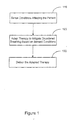
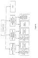
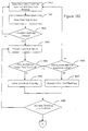
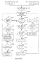
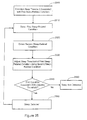
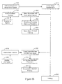
- the flowchart of Figure 1 illustrates a method for providing cardiac electrical therapy to treat disordered breathing in accordance with embodiments of the invention.
- the method includes sensing 110 one or more conditions affecting the patient.
- a cardiac electrical therapy is adapted 120 to treat disordered breathing based on the sensed conditions.
- the therapy may be adapted, for example, to achieve a desired therapeutic goal, to reduce the impact of the therapy, and/or to balance therapy efficacy with therapy impact. Therapy impact involves situations that may result in patient stress, patient discomfort, reduction in sleep quality, interactions with other pacing algorithms, and/or decrease in the life of the therapy device.
- the adapted therapy is delivered 130 to the patient. At least one of sensing the conditions, adapting the therapy, and delivering the adapted therapy is performed at least in part implantably.
- Implantably performing an operation comprises performing the operation using a component, device, or system that is partially or fully implanted within the body.
- Modification of the therapy may involve initiating the therapy, terminating the therapy or adjusting a therapy parameter.
- modification of the cardiac electrical therapy may involve cardiac pacing using different pacing vectors, pacing in fewer or more heart chambers, increasing or decreasing the pacing energy, non-excitatory pacing, such as sub-threshold pacing and/or pacing during a refractory period.
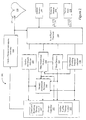
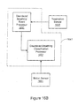
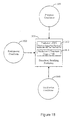
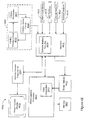
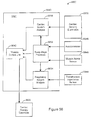
- FIG. 2 illustrates a therapy system 200 that may be used to implement a disordered breathing therapy methodology in accordance with embodiments of the invention.
- Figure 2 illustrates a system 200 that may be used to provide cardiac electrical therapy for disordered breathing as well as cardiac rhythm therapy.
- Various cardiac rhythm therapies including single chamber cardiac pacing, dual chamber cardiac pacing, biventricular cardiac pacing, defibrillation, cardioversion, and/or cardiac resynchronization therapy, among other cardiac arrhythmia therapies may be provided by the therapy system 200. Delivery of one or more cardiac rhythm therapies may be operated separately or in cooperation with delivery of disordered breathing therapy.
- illustrative embodiments involve therapy systems having an implantable therapy control system, an implantable therapy delivery system, and implantable sensors
- the therapy system 200 may be configured so that all of the system 200 or portions of the system 200 are arranged externally to the patient.
- Sensors and other components of the sensing system may involve patient-external sensors or components, patient-internal sensors or components or a combination of patient-external and patient-internal sensors or other components.
- the therapy system 200 may include circuitry for providing cardiac rhythm management therapy, in addition to and possibly in cooperation with, disordered breathing therapy.
- the therapy controller 265 may control a cardiac electrical stimulation therapy for cardiac arrhythmia, including bradyarrhythmia and/or tachyarrhymia.
- the system may include an arrhythmia detector 252.
- the cardiac electrical stimulation generator 232 is coupled to a lead system having implanted electrodes 231 to electrically couple the heart 230 to the electrical stimulation generator 232.
- the cardiac therapy module 265 receives cardiac signals from the implanted cardiac electrodes 231 and analyzes the cardiac signals to determine an appropriate cardiac rhythm therapy.
- the cardiac rhythm therapy may include pacing therapy controlled by the cardiac rhythm therapy controller 269 to treat cardiac rhythms that are too slow. In this situation, the cardiac rhythm therapy controller 269 controls the cardiac stimulation circuit 232 to deliver of periodic low energy pacing pulses to one or more heart chambers to ensure that the periodic contractions of the heart are maintained at a hemodynamically sufficient rate.
- the cardiac therapy may also include therapy to terminate tachyarrhythmia, wherein the heart rate is too fast.
- the cardiac arrhythmia detector 252 detects episodes of tachyarrhythmia, such as ventricular tachycardia and/or fibrillation.
- the arrhythmia detector 252 recognizes cardiac signals indicative of tachyarrhythmia.
- the cardiac rhythm therapy controller may initiate the delivery of high energy electrical pulses from the stimulation generator 232 to the heart 230 0 to terminate the arrhythmia.
- Conditions affecting the patient may be detected using one or more patient-internal sensors 280, one or more patient-external sensors 290, and one or more patient input devices 270.
- One or more of the sensors 280, 290, and/or input devices 270 may be network-based.
- the sensors and/or other components of the therapy system 200 may be coupled using wired or wireless communications links.
- some or all of the patient-internal sensors 280, patient-external sensors 290, and patient input devices 270 may use remote communication capabilities, such as a wireless Bluetooth communications lime or a proprietary wireless conununications protocol.
- a wireless communications link couples the sensors 280, 290, input devices 270, to other components of the therapy system 200.
- the therapy system 200 includes signal processing circuitry 250 for processing the signals received from the patient-internal sensors 280, patient-external sensors 290, and/or other input devices 270 used for detecting physiological or non-physiological conditions.
- the patient-internal sensors may include one or more implanted cardiac electrodes 231.
- the cardiac electrodes 231, patient-internal sensors 280, patient-external sensors 290, and/or other input device 270 may be used to sense or detect one or more of the conditions listed in Table 1.
- heart rate and tidal volume may be determined using cardiac and respiration signals derived from an intracardiac electrocardiogram (EGM) sensor and transthoracic impedance sensor, respectively.
- EGM and transthoracic impedance signals may be used in connection with cardiac rhythm management, as well as disordered breathing therapy.
- the therapy system 200 may derive additional physiological and non-physiological patient conditions using additional sensors and input devices. For example, a patient's activity may be detected using an implantable accelerometer, the patient's perceptions of restful sleep may be input using an external patient input device, and the patient's proximity to bed may be detected using a proximity to bed sensor involving both patient-internal and patient-external components.
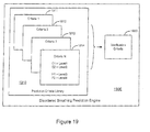
- the therapy system 200 may include disordered breathing predictor/detector 258 that receives inputs from the sensors and input devices 231, 280, 290, 270 through the input signal processing circuitry 250.
- the disordered breathing predictor/detector 258 uses the sensed conditions to detect, predict, and/or classify episodes of disordered breathing.
- the disordered breathing detector/predictor may include circuitry for implementing a respiration monitor, including a user-accessible respiratory logbook as described in more detail herein.
- the disordered breathing predictor/detector 258 is coupled to the therapy controller 265 that includes circuitry for controlling cardiac electrical stimulation therapy for disordered breathing 267.
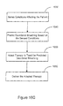
- Patient respiration including disordered breathing events, may be monitored by a respiration monitor 254. Respiration monitoring may involve event-based collection of medical information associated with respiratory events.
- Therapy to treat disordered breathing may be initiated, modified, or terminated by the disordered breathing therapy control circuitry 267, for example, based upon detection or prediction of disordered breathing. Additionally or alternatively, the disordered breathing therapy control circuitry 267 may adapt the disordered breathing therapy using medical information collected by the respiration monitor 254.
- disordered breathing occurs most frequently during sleep and may cause the patient to arouse from sleep repeatedly throughout the night.
- sleep information e.g., sleep onset/offset, sleep stage, and/or sleep arousal information
- sleep information may be used by the disordered breathing predictor/detector 258 in connection with the detection and/or prediction of disordered breathing.
- the disordered breathing predictor/detector 258 may sense for disordered breathing events only during sleep, or may verify an initial detection/prediction of disordered breathing by determining if the patient is asleep.
- the therapy controller 265 controls the delivery an appropriate cardiac electrical therapy to mitigate the disordered breathing.
- pacing to mitigate disordered breathing may involve pacing at a rate exceeding an intrinsic rate, pacing at a rate above the patient's normal pacing rate, or above the patient's normal sleep rate, pacing according to selected modes, e.g., bi-ventricular or single chamber modes, or pacing at a predetermined energy level that is above or below a capture threshold.
- the pacing may involve any or all of the heart chambers, for example, right and left atria and right and left ventricles, and may further involve multi-site pacing within one heart chamber.
- the pacing pulses may be delivered to left and right ventricles substantially simultaneously, or according to other timing sequences.
- Cardiac electrical stimulation therapy for disordered breathing may involve non-excitatoy pacing, such as sub-threshold pacing and/or pacing during a refractory period.
- the cardiac electrical therapy for disordered breathing may be coordinated with therapy provided to the patient to treat cardiac rhythm disorders, including, for example, bradycardia and/or cardiac resynchronization therapies.
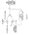
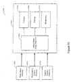
- FIG. 3 is a partial view of an implantable device that may include circuity for implementing cardiac stimulation therapy for disordered breathing in accordance with embodiments of the invention.
- the implantable device comprises a cardiac rhythm management device (CRM) 300 including an implantable electrical stimulation generator 305 electrically and physically coupled to an intracardiac lead system 310. Portions of the intracardiac lead system 310 are inserted into the patient's heart 390.
- the intracardiac lead system 310 includes one or more electrodes configured to sense electrical cardiac activity of the heart, deliver electrical stimulation to the heart, sense the patient's transthoracic impedance, and/or sense other physiological parameters, e,g, cardiac chamber pressure or temperature. Portions of the housing 301 of the pulse generator 305 may optionally serve as a can electrode.
- Communications circuitry is disposed within the housing 301 for facilitating communication between the electrical stimulation generator 305 and remote devices having wireless communication functionality, such as a portable or bed-side communication station, patient-carried/worn communication station, or external programmer, for example.
- the wireless communications circuitry can also facilitate unidirectional or bidirectional communication with one or more implanted, external, cutaneous, or subcutaneous physiologic or non-physiologic sensors, patient-input devices and/or other information systems.
- the housing 301 of the electrical stimulation generator 305 may optionally incorporate various sensors, including, for example, a motion sensor that may be programmed to sense various conditions.
- the motion sensor may be optionally configured to sense snoring, patient activity level, and/or chest wall movements associated with respiratory effort, for example.
- the motion detector may be implemented as an accelerometer positioned in or on the housing 301 of the electrical stimulation generator 305. If the motion sensor is implemented as an accelerometer, the motion sensor may also provide respiratory information, e.g. rales, coughing, and cardiac information, e.g. S1-S4 heart sounds, murmurs, and/or other acoustic information.
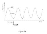
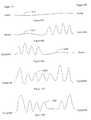
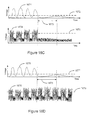
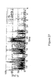
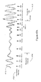
- the voltage signal developed at the impedance sense electrode 352, illustrated in Figure 5A is proportional to the patient's transthoracic impedance and represents the patient's respiration waveform.
- the transthoracic impedance increases during respiratory inspiration 510 and decreases during respiratory expiration 520.
- the peak-to-peak transition of the transthoracic impedance is proportional to the amount of air moved in one breath, denoted the tidal volume.
- the amount of air moved per minute is denoted the minute ventilation.
- a normal "at rest" respiration pattern, e.g., during non-REM sleep, includes regular, rhythmic inspiration - expiration cycles without substantial interruptions, as indicated in Figure 5A .
- the housing 301 of the electrical stimulation generator 305 may include circuitry for detecting cardiac arrhythmias and/or for controlling pacing and/or defibrillation therapy in the form of electrical stimulation pulses or shocks delivered to the heart through the lead system 310. Also disposed within the housing 301 may be circuitry for controlling cardiac electrical stimulation therapy for disordered breathing, including a sleep quality monitor 254, sleep processor 256, disordered breathing detector/predictor 258, therapy assessment processor 260, and/or therapy controller circuitry 265 as described in connection with Figure 2 .
- an implantable transthoracic cardiac sensing and/or stimulation (ITCS) device may be implemented to detect/monitor normal and abnormal cardiac and/or respiratory activity, and may be configured to deliver an appropriate therapy in response to abnormal activity or conditions.
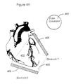
- An ITCS device 400 of the present invention may be configured for monitoring, diagnosing, and/or treating cardiac and disordered breathing events/conditions.
- An ITCS device 400 is typically implemented to sense activity of both the cardiac system and the respiratory system. Using appropriate sensors, the ITCS device 400 may be implemented to detect and monitor a variety of disordered breathing conditions, including sleep and non-sleep related disordered breathing conditions.
- An ITCS device 400 may further be implemented to detect sleep, and may further be implemented to detect stages of patient sleep.
- An ITCS device 400 so implemented may be configured to perform a variety of sensing, monitoring, diagnosing, and/or therapy control/coordination functions, including those described herein and in the references respectively incorporated herein.
- the primary housing (e.g., the active or non-active can) 402 of the ITCS device. 400 may be configured for positioning outside of the rib cage at an intercostal or subcostal location, within the abdomen, or in the upper chest region (e.g., subclavian location, such as above the third rib).
- one or more electrodes may be located on the primary housing 402 and/or at other locations (e.g., electrode 404) about, but not in direct contact with the heart, great vessels or coronary vasculature.
- a pulse generator and a cardiac stimulation controller are disposed in the primary housing 402.
- the cardiac stimulator controller determines and coordinates appropriate cardiac and/or respiratory therapy to be delivered to a patient, and the pulse generator produces the appropriate energy waveforms associated with a selected therapy.
- a cardiac activity detector configured to detect normal and abnormal (e.g., arrhythmic) cardiac activity.
- the ITCS device 400 depicted in Figure 4A may be configured in a manner described hereinabove or may have other configurations.
- An ITCS device 400 of the present invention may be implemented to include one or more of cardiac and/or respiratory detection/monitoring circuitry (e.g., for cardiac activity, breathing patterns such as from transthoracic impedance signals, heart sounds, blood gas/chemistry such as oxygen saturation and/or pH), cardiac and respiratory diagnostics circuitry, and cardiac and respiratory therapy circuitry.
- An ITCS device 400 of the present invention may be implemented to provide for upgradeability in terms of functionality and/or configuration.
- an ITCS device 400 may be implemented as an upgradeable or reconfigurable cardiac/respiratory monitor or stimulation device.
- An ITCS device 400 in accordance with embodiments of the present invention provides for patient breathing monitoring and disordered breathing detection and/or prediction. Such embodiments may further provide treatment for detected or predicted disordered breathing events or conditions, as determined by a therapy controller or in response to an externally generated command signal (such as received from an advanced patient management system or programmer). Detection and treatment of disordered breathing and/or respiratory conditions may be facilitated by use of an ITCS device 400 having appropriate sensing/detection/therapy delivery capabilities, or by cooperative use of an ITCS device 400 and an external programmer or an advanced patient management system via a communications interface.
- a subcutaneous electrode 404 may be positioned under the skin in the chest region and situated distal from the housing 402.
- the subcutaneous and, if applicable, housing electrode(s) may be positioned about the heart at various locations and orientations, such as at various anterior and/or posterior locations relative to the heart.
- the subcutaneous electrode 404 is coupled to circuitry within the housing 402 via a lead assembly 406.
- One or more conductors e.g., coils or cables
- the lead assembly 406 is generally flexible and has a construction similar to conventional implantable, medical electrical leads (e.g., defibrillation leads or combined defibrillation/pacing leads).
- the lead assembly 406 is constructed to be somewhat flexible, yet has an elastic, spring, or mechanical memory that retains a desired configuration after being shaped or manipulated by a clinician.
- the lead assembly 406 may incorporate a gooseneck or braid system that may be distorted under manual force, to take on a desired shape. In this manner, the lead assembly 406 may be shape-fit to accommodate the unique anatomical configuration of a given patient, and generally retains a customized shape after implantation. Shaping of the lead assembly 406 according to this configuration may occur prior to, and during, ITCS device 400 implantation.
- the electrode support assembly and the housing 402 define a unitary structure (e.g., a single housing/unit).
- the electronic components and electrode conductors/connectors are disposed within or on the unitary ITCS device 400 housing/electrode support assembly. At least two electrodes are supported on the unitary structure near opposing ends of the housing/electrode support assembly.
- the unitary structure may have an arcuate or angled shape, for example.
- the electrode support assembly defines a physically separable unit relative to the housing 402.
- the electrode support assembly includes mechanical and electrical couplings that facilitate mating engagement with corresponding mechanical and electrical couplings of the housing 402.
- a header block arrangement may be configured to include both electrical and mechanical couplings that provide for mechanical and electrical connections between the electrode support assembly and housing 402.
- the header block arrangement may be provided on the housing 402 or the electrode support assembly.
- a mechanical/electrical coupler may be used to establish mechanical and electrical connections between the electrode support assembly and housing 402.
- a variety of different electrode support assemblies of varying shapes, sizes, and electrode configurations may be made available for physically and electrically connecting to a standard ITCS device 400 housing 402.
- the electrodes and the lead assembly 406 may be configured to assume a variety of shapes.
- the lead assembly 406 may have a wedge, chevron, flattened oval, or a ribbon shape
- the subcutaneous electrode 404 may include a number of spaced electrodes, such as an array Or band of electrodes.
- two or more subcutaneous electrodes 404 may be mounted to multiple electrode support assemblies 406 to achieve a desired spaced relationship amongst subcutaneous electrodes 404.
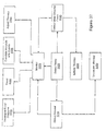
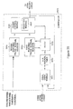
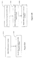
- FIG. 4B is a block diagram depicting various components of an ITCS device 400 in accordance with one configuration.
- the ITCS device 400 incorporates a processor-based control system 405 which includes a micro-processor 426 coupled to appropriate memory (volatile and non-volatile) 409, it being understood that any logic-based control architecture may be used.
- the control system 405 is coupled to circuitry and components to sense, detect, and analyze electrical signals produced by the heart and deliver electrical stimulation energy to the heart under predetermined conditions to treat cardiac arrhythmias.
- the control system 405 and associated components also provide pacing therapy to the heart.
- the electrical energy delivered by the ITCS device 400 may be in the form of low energy pacing pulses, non-excitatory energy (e.g., sub-threshold stimulation energy) or high-energy pulses for cardioversion or defibrillation.
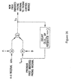
- Noise reduction circuitry 403 may also be incorporated after sensing circuitry 422 in cases where high power or computationally intensive noise reduction algorithms are required.
- the noise reduction circuitry 403, by way of amplifiers used to perform operations with the electrode signals, may also perform the function of the sensing circuitry 424. Combining the functions of sensing circuitry 424 and noise reduction circuitry 403 may be useful to minimize the necessary componentry and lower the power requirements of the system.
- the detection circuitry 422 is coupled to, or otherwise incorporates, noise reduction circuitry 403.
- the noise reduction circuitry 403 operates to improve the signal-to-noise ratio (SNR) of sensed cardiac signals by removing noise content of the sensed cardiac signals introduced from various sources.
- SNR signal-to-noise ratio
- Typical types of transthoracic cardiac signal noise includes electrical noise and noise produced from skeletal muscles, for example.
- Detection circuitry 422 typically includes a signal processor that coordinates analysis of the sensed cardiac signals and/or other sensor inputs to detect cardiac arrhythmias, such as, in particular, tachyarrhythmia. Rate based and/or morphological discrimination algorithms may be implemented by the signal processor of the detection circuitry 422 to detect and verify the presence and severity of an arrhythmic episode.
- the detection circuitry 422 communicates cardiac signal information to the control system 405.
- Memory circuitry 409 of the control system 405 contains parameters for operating in various sensing, defibrillation, and, if applicable, pacing modes, and stores data indicative of cardiac signals received by the detection circuitry 422.
- the memory circuitry 409 may also be configured to store historical ECG and therapy data, which may be used for various purposes and transmitted to an external receiving device as needed or desired.
- the ITCS device 400 may include diagnostics circuitry 410.
- the diagnostics circuitry 410 typically receives input signals from the detection circuitry 422 and the sensing circuitry 424.
- the diagnostics circuitry 410 provides diagnostics data to the control system 405, it being understood that the control system 405 may incorporate all or part of the diagnostics circuitry 410 or its functionality.
- the control system 405 may store and use information provided by the diagnostics circuitry 410 for a variety of diagnostics purposes. This diagnostic information may be stored, for example, subsequent to a triggering event or at predetermined intervals, and may include system diagnostics, such as power source status, therapy delivery history, and/or patient diagnostics.
- the diagnostic information may take the form of electrical signals or other sensor data acquired immediately prior to therapy delivery.
- the control system 405 processes cardiac signal data received from the detection circuitry 422 and initiates appropriate tachyarrhythmia therapies to terminate cardiac arrhythmic episodes and return the heart to normal sinus rhythm.
- the control system 405 is coupled to shock therapy circuitry 416.
- the shock therapy circuitry 416 is coupled to the subcutaneous electrode(s) 414 and the can or indifferent electrode 407 of the ITCS device 400 housing.
- the shock therapy circuitry 416 delivers cardioversion and defibrillation stimulation energy to the heart in accordance with a selected cardioversion or defibrillation therapy.
- the shock therapy circuitry 416 is controlled to deliver defibrillation therapies, in contrast to a configuration that provides for delivery of both cardioversion and defibrillation therapies.
- the ITCS device 400 shown in Figure 4B is configured to receive signals from one or more physiologic and/or non-physiologic sensors. Depending on the type of sensor employed, signals generated by the sensors may be communicated to transducer circuitry coupled directly to the detection circuitry 422 or indirectly via the sensing circuitry 424. It is noted that certain sensors may transmit sense data to the control system 405 without processing by the detection circuitry 422.
- FIGS. 4A-4E The components, functionality, and structural configurations depicted in Figures 4A-4E are intended to provide an understanding of various features and combination of features that may be incorporated in an ITCS device 400. It is understood that a wide variety of ITCS and other implantable cardiac monitoring and/or stimulation device configurations are contemplated, ranging from relatively sophisticated to relatively simple designs. As such, particular ITCS or cardiac monitoring and/or stimulation device configurations may include particular features as described herein, while other such device configurations may exclude particular features described herein.
- an ITCS device 400 may be implemented to include a subcutaneous electrode system that provides for one or both of cardiac sensing and arrhythmia therapy delivery.
- an ITCS device 400 may be implemented as a chronically implantable system that performs monitoring, diagnostic and/or therapeutic functions. The ITCS device 400 may automatically detect and treat cardiac arrhythmias.
- an ITCS device 400 includes a pulse generator and one or more electrodes that are implanted subcutaneously in the chest region of the body, such as in the anterior thoracic region of the body.
- the ITCS device 400 may be used to provide atrial and/or ventricular therapy for bradycardia and tachycardia arrhythmias.
- Tachyarrhythmia therapy may include cardioversion, defibrillation and anti-tachycardia pacing (ATP), for example, to treat atrial or ventricular tachycardia or fibrillation.
- Bradycardia therapy may include temporary post-shock pacing for bradycardia or asystole.
- an ITCS device 400 may utilize conventional pulse generator and subcutaneous electrode implant techniques.
- the pulse generator device and electrodes may be chronically implanted subcutaneously.
- Such an ITCS may be used to automatically detect and treat arrhythmias similarly to conventional implantable systems.
- the ITCS device 400 may include a unitary structure (e.g., a single housing/unit).
- the electronic components and electrode conductors/connectors are disposed within or on the unitary ITCS device 400 housing/electrode support assembly.
- the ITCS device 400 contains the electronics and may be similar to a conventional implantable defibrillator.
- High voltage shock therapy may be delivered between two or more electrodes, one of which may be the pulse generator housing (e.g., can), placed subcutaneously in the thoracic region of the body.
- the pulse generator housing e.g., can
- the ITCS device 400 may also provide lower energy electrical stimulation for bradycardia therapy.
- the ITCS device 400 may provide brady pacing similarly to a conventional pacemaker.
- the ITCS device 400 may provide temporary post-shock pacing for bradycardia or asystole. Sensing and/or pacing may be accomplished using sense/pace electrodes positioned on an electrode subsystem also incorporating shock electrodes, or by separate electrodes implanted subcutaneously.
- An ITCS device 400 provides an easy to implant therapeutic, diagnostic or monitoring system.
- the ITCS system may be implanted without the need for intravenous or intrathoracic access, providing a simpler, less invasive implant procedure and minimizing lead and surgical complications.
- this system would have advantages for use in patients for whom transvenous lead systems cause complications. Such complications include, but are not limited to, surgical complications, infection, insufficient vessel patency, complications associated with the presence of artificial valves, and limitations in pediatric patients due to patient growth, among others.
- An ITCS system according to this approach is distinct from conventional approaches in that it may be configured to include a combination of two or more electrode subsystems that are implanted subcutaneously in the anterior thorax.
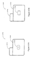
- Figure 4CA illustrates the housing 431 and can electrode 433 placed subcutaneously, superior to the heart 440 in the left pectoral region, which is a location commonly used for conventional pacemaker and defibrillator implants.
- the second electrode subsystem 435 may include a coil electrode mounted on the distal end of a lead body 437, where the coil is approximately 3-15 French in diameter and 5-12 cm in length.
- the coil electrode may have a slight preformed curve along its length.
- the lead may be introduced through the lumen of a subcutaneous sheath, through a common tunneling implant technique, and the second electrode subsystem 435, e.g., including a coil electrode, may be placed subcutaneously, deep to any subcutaneous fat and adjacent to the underlying muscle layer.
- the second electrode subsystem 435 is located approximately parallel with the inferior aspect of the right ventricle of the heart 440, just inferior to the right ventricular free wall, with one end extending just past the apex of the heart 440.
- the tip of the electrode subsystem 435 may extend less than about 3 cm and may be about 1-2 cm left lateral to the apex of the heart 440.
- This electrode arrangement may be used to include a majority of ventricular tissue within a volume defined between the housing 431 and the second electrode subsystem 435.
- the volume including a majority of ventricular tissue may be associated with a cross sectional area bounded by lines drawn between the ends of the electrode subsystems 433, 435 or between active elements of the electrode subsystems 433, 435.
- the lines drawn between active elements of the electrode subsystems 433, 435 may include a medial edge and a lateral edge of the can electrode 433, and a proximal end and a distal end of a coil electrode utilized within the second electrode subsystem 435.
- Arranging the electrode subsystems so that a majority of ventricular tissue is contained within a volume defined between the active elements of the electrode subsystems 433, 435 provides an efficient position for defibrillation by increasing the voltage gradient in the ventricles of the heart 440 for a given applied voltage between electrode subsystems 433, 435.
- the ITCS device housing 431 containing the electronics is not used as an electrode.
- an electrode system including two electrode subsystems 438, 439 coupled to the housing 431 may be implanted subcutaneously in the chest region of the body, such as in the anterior thorax.
- the first and the second electrode subsystems 438, 439 are placed in opposition with respect to the ventricles of the heart 440, with the majority of the ventricular tissue of the heart 440 included within a volume defined between the electrode subsystems 438, 439.
- the first electrode system 438 is located superior to the heart 440 relative to a superior aspect of the heart 440, e.g., parallel to the left ventricular free wall.
- the second electrode system 439 is located inferior to the heart 440 and positioned in relation to an inferior aspect of the heart 440, e.g., parallel to the right ventricular free wall.
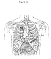
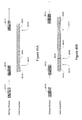
- Figures 4F-4H provide additional detailed views of subcutaneous electrode subsystem placement considered particularly useful with ITCS devices incorporating disordered breathing detection in accordance with embodiments of the present invention.
- Figure 4F illustrates first and second electrode subsystems configured as a can electrode 462 and a coil electrode 464, respectively.
- Figure 4F illustrates the can electrode 462 located superior to the heart 460 in the left pectoral region and the coil electrode 464 located inferior to the heart 460, parallel to the right ventricular free wall of the heart 460.
- the can electrode 462 is placed superior to the heart 460 in the right pectoral region.
- the coil electrode 464 is located inferior to the heart. In one arrangement the coil electrode is located relative to an inferior aspect of the heart 460, for example, the apex of the heart.
- the can electrode 462 and the coil electrode 464 are positioned so that the majority of ventricular tissue is included within a volume defined between the can electrode 462 and the coil electrode 464.
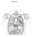
- Figure 4G illustrates a cross sectional area 465 formed by the lines drawn between active elements of the can electrode 462 and the coil electrode 464.
- Lines drawn between active areas of the electrodes 462, 464 may be defined by a medial edge and a lateral edge of the can electrode 462, and a proximal end and a distal end of a coil electrode utilized as the second electrode subsystem 464.
- the coil electrode 464 extends a predetermined distance beyond the apex of the heart 460, e.g. less than about 3 cm.
- Figure 4H illustrates a configuration wherein the pulse generator housing 461 does not include an electrode.
- two electrode subsystems are positioned about the heart so that a majority of ventricular tissue is included within a volume defined between the electrode subsystems.
- the first and second electrodes are configured as first and second coil electrodes 468, 469.
- the first coil electrode 468 is located superior to the heart 460 and may be located relative to a superior aspect of the heart, e.g., the left ventricular free wall.
- the second coil electrode 469 is located inferior to the heart 460.
- the second electrode 469 may be located in relation to an inferior aspect of the heart 460.
- the second electrode 469 is positioned parallel to the right ventricular free wall with a tip of the electrode 469 extending less than about 3 cm beyond the apex of the heart 460.
- the volume defined between the electrodes may be defined by the cross sectional area 465 bounded by lines drawn between active areas of the electrodes 468, 469.
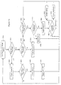
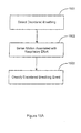
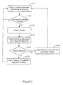
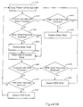
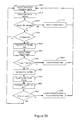
- detection of disordered breathing events may be used in connection with adapting a therapy to treat disordered breathing.
- detection and assessment of disordered breathing is used to adapt (initiate, modify and/or terminate) therapy delivery.
- disordered breathing events detected during and/or after therapy delivery may be used to assess the effectiveness of the disordered breathing therapy.
- episodes of disordered breathing may be detected and classified by analyzing the patient's respiration patterns and/or other conditions associated with disordered breathing.
- the cardiac electrical therapy for disordered breathing may be adapted based on detected episodes of disordered breathing.
- one or more episodes of disordered breathing are detected and the cardiac electrical therapy is initiated or increased to treat the detected episodes.
- Adaptation of the therapy may continue, enabling the system to deliver a therapeutically appropriate therapy throughout the disordered breathing episode or episodes. If the system determines that the disordered breathing has mitigated or ceased, then the therapy may be reduced or terminated. Therapy may continue after the disordered breathing episode has stopped to prevent future occurrences of disordered breathing.
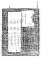
- Table 1 provides a representative set of conditions affecting the patient that may be used to detect disordered breathing and/or to adapt the disordered breathing therapy. Table 1 also provides example sensing methods that may be employed to sense the conditions.
- Table 1 Condition Category Condition used to detect/predict disordered breathing and/or adapt therapy Sensing method examples Physiological Sleep and Respiration Quality/ Patient Comfort Sleep Fragmentation (arousal-based measures) Steep efficiency Electroencephlogram (EEG) Arousals/hour Electromyogram (EMG) Undisturbed sleep time Activity sensor Undisturbed sleep efficiency (accelerometer, Sleep disturbance index Transthoracic impedance Undisturbed sleep time sensor) Sleep staging Posture sensor Sleep stage detector (muscle atonia sensor) Disturbed Breathing-Based Measures Percent time in periodic breathing Transthoracic impedance sensor Apnea/hypopnea index Patient-reported Restful sleep Patient log Patient comfort Cardiovascular System Heart rate EGM Heart rate variability (HRV) Electrocardiogram (ECG) Ventricular
- Detection of disordered breathing may involve detecting one or more conditions indicative of disordered breathing listed in Table 1.
- the patient conditions listed in Table 1 may be employed in a multi-sensor approach to detect and confirm episodes of disordered breathing.
- the accuracy of a preliminary disordered breathing detection may be enhanced by verifying the patient is asleep, in bed, inactive, lying down, or that the present environmental conditions are associated with disordered breathing in the patient.
- Table 2 provides examples of how a representative subset of the physiological and non-physiological conditions listed in Table 1 may be used in connection with disordered breathing detection.
- Table 2 Condition Type Condition Examples of how condition may be used in disordered breathing detection Physiological Heart rate Decrease in heart rate may indicate disordered breathing episode. Decrease in heart rate may indicate the patient is asleep. Heart rate variability Disordered breathing causes hear rate variability to decrease. Changes in HRV associated with sleep disordered breathing may be observed while the patient is awake or asleep Ventricular filling pressure May be used to identify/predict pulmonary congestion associated with respiratory disturbance. Blood pressure Swings in on-line blood pressure measures are associated with apnea. Disordered breathing generally increases blood pressure variability - these changes may be observed while the patient is awake or asleep.
- Snoring Snoring is associated with a higher incidence of obstructive sleep apnea and may be used to detect disordered breathing.
- Respiration pattern/rate Respiration patterns including, e.g., respiration rate, may be used to detect disordered breathing episodes.
- Respiration patterns may be used to determine the type of disordered breathing.
- Respiration patterns may be used to detect that the patient is asleep.
- Patency of upper airway Patency of upper airway is related to obstructive sleep apnea and may be used to detect episodes of obstructive sleep apnea.
- Pulmonary congestion Pulmonary congestion is associated with respiratory disturbances. Sympathetic nerve activity End of apnea associated with a spike in SNA.
- Muscle atonia Muscle atonia may be used to detect REM and non-REM sleep. Eye movement Eye movement may be used to detect REM and non-REM sleep Non-physiological Contextual Temperature Ambient temperature may be a condition predisposing the patient to episodes of disordered breathing and may be useful in disordered breathing detection. Humidity Humidity may be a condition predisposing the patient to episodes of disordered breathing and may be useful in disordered breathing detection. Pollution Pollution may be a condition predisposing the patient to episodes of disordered breathing and may be useful in disordered breathing detection. Posture Posture may be used to confirm or determine the patient is asleep. Activity Patient activity may be used in relation to sleep detection. Location Patient location may used to determine if the patient is in bed as a part of sleep detection.
- Obstructive sleep apneas may be terminated by arousal from sleep several seconds after the apneic peak, allowing the breathing to resume.
- surges in sympathetic nerve activity, blood pressure, and heart rate may occur.
- the adverse effects of obstructive apnea are not confined to sleep. Waking conditions such as sympathetic nerve activity and systemic blood pressure are increased.
- Central sleep apnea is generally caused by a failure of respiratory control signals from the brain.
- Central sleep apnea is a component of Cheyne-Stokes respiration (CSR), a respiration pattern primarily observed in patients suffering from chronic heart failure (CHF).
- Cheyne-Stokes respiration is a form of periodic breathing in which central apneas and hypopneas alternate with periods of hyperventilation causing a waxing-waning pattern of tidal volume.
- CHF chronic heart failure
- obstructive sleep apnea and central sleep apnea may coexist. In these patients, there may be a gradual shift from predominantly obstructive apneas at the beginning of the night to predominantly central apneas at the end of the night.
- an increase in carbon dioxide sensitivity may minimize perturbations in PaCO 2 , thus protecting them against the long-term consequences of hypercapnia, an excess of carbon dioxide in the blood.
- This protective mechanism may be advantageous while the patient is awake, however, the increased sensitivity to carbon dioxide may disrupt breathing during sleep.
- PaCO 2 levels increase. If the PaCO 2 level decreases below level referred to as the apneic threshold, ventilation ceases, central sleep apnea ensues, and PaCO 2 rises to previous levels.
- the posture of CHF patients during sleep may also be implicated in triggering apnea.
- the prone posture may create central fluid accumulation and pulmonary congestion causing the patient to reflexively hyperventilate.
- Hyperventilation may initiate the cyclical pattern of hyperventilation-apnea described above.
- Arousals are not necessarily required in central sleep apneas for the resumption of breathing at the termination of the apneic event.
- the arousals follow the initiation of breathing and may facilitate the development of oscillations in ventilation by recurrently stimulating hyperventilation and reducing PaCO 2 below the apneic threshold.
- the pattern of alternating hyperventilation and apnea is sustained by the combination of increased respiratory drive, pulmonary congestion, arousals, and apnea-induced hypoxia causing PaCO 2 oscillations above and below the apneic threshold. Shifts in the patient's state of consciousness, particularly with repeated arousals, may further destabilize breathing.
- the transition to NREM sleep may be accompanied by a transient loss of respiratory drive resulting in a central apnea.
- the PaCO 2 rises until it reaches the new higher threshold level and initiates breathing. If sleep becomes firmly established, regular breathing resumes.
- the increased PaCO 2 level associated with sleep is now relatively too high for a state of wakefulness and will stimulate hyperventilation.
- arousals terminate obstructive sleep apneas
- arousals trigger the respiratory oscillations associated with central apneas, particularly Cheyne-Stokes respiration.
- sleep disordered breathing is also associated with a number of secondary or chronic responses, including, for example, chronic decrease in heart rate variability (RRV) and blood pressure changes.
- RRV heart rate variability
- Patients with central sleep apnea may have higher urinary and circulating norepinephrine concentrations and lower PaCO 2 during both sleep and wakefulness.
- Acute responses to disordered breathing are associated with physiological conditions that are modulated during an ongoing disordered breathing event. Sensing conditions modulated by the acute responses to disordered breathing may be used to detect a disordered breathing event contemporaneously with the occurrence of the disordered breathing event. Chronic responses to disordered breathing may be modulated by an aggregation of disordered breathing events that occur over time. Chronic responses to disordered breathing may be used to determine if disordered breathing events have occurred.
- Both acute and chronic responses to disordered breathing may be used to asses the efficacy and impact of disordered breathing therapy.
- a first subset of patient conditions may be used to detect disordered breathing, including presently occurring events, and/or an aggregation of events occurring over time.
- a second subset of patient conditions may be used to assess the disordered breathing therapy.
- the efficacy of the therapy may be assessed and the therapy may be adapted to enhance the efficacy based on the assessment.
- the therapy may be assessed to determine an impact of the therapy on the patient.
- the therapy may be adapted to reduce therapy impact of the therapy on the patient based on the assessment.
- Conditions used to assess therapy effectiveness may be different from, or the same as, conditions used to assess an impact of the therapy on the patient.
- Table 3 provides a representative set of conditions that may be used for therapy assessment.
- Table 3 Condition Therapy Impact Therapy Efficacy May be used to assess therapy impact during sleep. Restful sleep (Patient reported) May be used to assess therapy impact during sleep. Discomfort (Patient reported) May be used to assess therapy impact. Pacing algorithm interaction May be used to assess therapy impact. Remaining useful life of therapy device May be used to assess therapy impact. Disturbed Breathing-Based Measures May be used to analyze/assess efficacy of therapy to mitigate disordered breathing episodes.
- Respiration quality (Patient reported) May be used to analyze/assess efficacy of therapy to mitigate disordered breathing episodes.
- Heart rate variability (HRV) Disordered breathing causes heart rate variability to decrease.
- Therapy may be modified based on changes in HRV Blood pressure Disordered breathing causes blood pressure increase
- SNA Sympathetic nerve activity
- Changes in sympathetic nerve activity are caused by disordered breathing.
- Therapy may be adjusted based on the level of SNA Blood chemistry
- a number of disordered breathing related changes may occur in a patient's blood chemistry, including, e.g., higher norepinephrine levels, and lower PaCO 2
- patient conditions that may be used in connection with disordered breathing therapy, including detection of disordered breathing and/or therapy assessment, for example, are not limited m the representative sets listed ill Tables 1-3 or those described herein.
- illustrative sensing methods for detecting the patient conditions listed above are provided, it is understood that the patient conditions may be detected using a wide variety of technologies. The invention is not limited to the particular conditions or the particular sensing technologies discussed herein in connection with the illustrative embodiments.
- disordered breathing is detected, and therapy for treating disordered breathing is adapted based on the detection of disordered breathing.
- a methodology for adapting the disordered breathing therapy is illustrated by the flowchart of Figure 5B .
- One or more conditions affecting the patient are sensed 530 and disordered breathing is detected 540 based on the sensed conditions.
- a therapy is adapted 550 to treat the detected disordered breathing.
- the system delivers 560 the adapted therapy.
- the disordered breathing predictor/detector 258 may detect episodes of disordered breathing by monitoring the respiratory waveform output of a transthoracic impedance sensor.
- a hypopnea threshold When the tidal volume (TV) of the patient's respiration, as indicated by the transthoracic impedance signal, falls below a hypopnea threshold, then a hypopnea event is declared.
- a hypopnea event may be declared if the patient's tidal volume falls below about 50% of a recent average tidal volume or other baseline tidal volume value. If the patient's tidal volume falls further to an apnea threshold, e.g., about 10% of the recent average tidal volume or other baseline value, an apnea event is declared.
- FIG. 6 illustrates respiration intervals used for disordered breathing detection according to an embodiment of the invention.
- a respiration cycle is divided into an inspiration period corresponding to the patient inhaling, an expiration period, corresponding to the patient exhaling, and a non-breathing period occurring between inhaling and exhaling.
- Respiration intervals are established using inspiration 610 and expiration 620 thresholds.
- the inspiration threshold 610 marks the beginning of an inspiration period 630 and is determined by the transthoracic impedance signal rising above the inspiration threshold 610.
- the inspiration period 630 ends when the transthoracic impedance signal is maximum 640.
- a maximum transthoracic impedance signal 640 corresponds to both the end of the inspiration interval 630 and the beginning of the expiration interval 650.
- the expiration interval 650 continues until the transthoracic impedance falls below an expiration threshold 620.
- a non-breathing interval 660 starts from the end of the expiration period 650 and continues until the beginning of the next inspiration period 670.
- Detection of sleep apnea and severe sleep apnea is illustrated in Figure 7 .
- the patient's respiration signals are monitored and the respiration cycles are defined according to inspiration 730, expiration 750, and non-breathing 760 intervals as described in connection with Figure 6 .
- a condition of sleep apnea is detected when a non-breathing period 760 exceeds a first predetermined interval 790, denoted the sleep apnea interval.
- a condition of severe sleep apnea is detected when the non-breathing period 760 exceeds a second predetermined interval 795, denoted the severe sleep apnea interval.
- sleep apnea may be detected when the non-breathing interval exceeds about 10 seconds
- severe sleep apnea may be detected when the non-breathing interval exceeds about 20 seconds.
- Hypopnea is a condition of disordered breathing characterized by abnormally shallow breathing.
- Figures 8A-B are graphs of tidal volume derived from transthoracic impedance measurements. The graphs compare the tidal volume of a normal breathing cycle to the tidal volume of a hypopnea episode.
- Figure 8A illustrates normal respiration tidal volume and rate.
- hypopnea involves a period of abnormally shallow respiration.
- Figure 9 is a flowchart illustrating a method of apnea and/or hypopnea detection according to embodiments of the invention.
- Various parameters are established 901 before analyzing the patient's respiration for disordered breathing episodes, including, for example, inspiration and expiration thresholds, sleep apnea interval, severe sleep apnea interval, and hypopnea tidal volume threshold.
- the patient's transthoracic impedance is measured 905 as described in more detail above. If the transthoracic impedance exceeds 910 the inspiration threshold, the beginning of an inspiration interval is detected 915. If the transthoracic impedance remains below 910 the inspiration threshold, then the impedance signal is checked 905 periodically until inspiration 915 occurs.
- the patient's transthoracic impedance is monitored until a maximum value of the transthoracic impedance is detected 920. Detection of the maximum value signals an end of the inspiration period and a beginning of an expiration period 935.
- the expiration interval is characterized by decreasing transthoracic impedance.
- a non-breathing interval is detected 955.
- the transthoracic impedance does not exceed 960 the inspiration threshold within a first predetermined interval 965, denoted the sleep apnea interval, then a condition of sleep apnea is detected 970.
- Severe sleep apnea is detected 980 if the non-breathing period extends beyond a second predetermined interval 975, denoted the severe sleep apnea interval.
- the tidal volume from the peak-to-peak transthoracic impedance is calculated, along with a moving average of past tidal volumes 985.
- the peak-to-peak transthoracic impedance provides a value proportional to the tidal volume of the respiration cycle. This value is compared 990 to a hypopnea tidal volume threshold. If the peak-to-peak transthoracic impedance is consistent with 990 the hypopnea tidal volume threshold for a predetermined time 992, then a hypopnea cycle is detected 995.
- Another embodiment of the invention involves classifying respiration patterns as disordered breathing episodes based on the breath intervals and/or tidal volumes of one or more respiration cycles within the respiration patterns.
- the duration and tidal volumes associated with a respiration pattern are compared to duration and tidal volume thresholds.
- the respiration pattern is detected as a disordered breathing episode bused on the comparison.
- a breath interval is established for each respiration cycle.
- a breath interval represents the interval of time between successive breaths, as illustrated in Figure 10 .
- a breath interval 1030 may be defined in a variety of ways, for example, as the interval of time between successive maxima 1010, 1020 of the impedance signal waveform.
- Detection of disordered breathing involves the establishment of a duration threshold and a tidal volume threshold. If a breath interval exceeds the duration threshold, an apnea event is detected. Detection of sleep apnea, in accordance with this embodiment, is illustrated in the graph of Figure 10 . Apnea represents a period of non-breathing. A breath interval 1030 exceeding a duration threshold 1040, comprises an apnea episode.
- a hypopnea detection approach in accordance with embodiments of the invention, is illustrated in Figure 11 .
- Shallow breathing is detected when the tidal volume of one or more breaths is below a tidal volume threshold 1110. If the shallow breathing continues for an interval greater than a duration threshold 1120, then the breathing pattern represented by the sequence of shallow respiration cycles, is classified as a hypopnea event.
- Figures 12 and 13 provide charts illustrating classification of individual disordered breathing events and series of periodically recurring disordered breathing events, respectively.
- individual disordered breathing events may be grouped into apnea, hypopnea, tachypnea and other disordered breathing events.
- Apnea events are characterized by an absence of breathing.
- Intervals of reduced respiration are classified as hypopnea events.
- Tachypnea events include intervals of rapid respiration characterized by an elevated respiration rate.
- apnea and hypopnea events may be further subdivided as either central events, related to central nervous system dysfunction, or obstructive events, caused by upper airway obstruction.
- a tachypnea event may be further classified as a hyperpnea event, represented by hyperventilation, i.e., rapid deep breathing.
- a tachypnea event may alternatively be classified as rapid breathing, typically of prolonged duration.
- Figure 13 illustrates classification of combinations of periodically recurring disordered breathing events.
- Periodic breathing may be classified as obstructive, central or mixed.
- Obstructive periodic breathing is characterized by cyclic respiratory patterns with an obstructive apnea or hypopnea event in each cycle.
- Central periodic breathing involves cyclic respiratory patterns including a central apnea or hypopnea event in each cycle.
- Periodic breathing, illustrated in Figure 14F may also be of mixed origin.
- Mixed origin periodic breathing is characterized by cyclic respiratory patterns having a mixture of obstructive and central apnea events in each cycle.
- Figure 15 is a flow graph of a method for detecting disordered breathing in accordance with embodiments of the invention.
- the method illustrated in Figure 15 operates by classifying breathing patterns using breath intervals in conjunction with tidal volume and duration thresholds as previously described above.
- a duration threshold and a tidal volume threshold are established for determining both apnea and hypopnea breath intervals.
- An apnea episode is detected if the breath interval exceeds the duration threshold.
- a hypopnea episode is detected if the tidal volume of successive breaths remains less than the tidal volume threshold for a period in excess of the duration threshold.
- Mixed apnea/hypopnea episodes may also occur.
- the breath interval does not exceed 1515 the duration threshold, then the tidal volume of the breath is checked 1535. If the tidal volume does not exceed 1535 the tidal volume threshold, the breathing pattern is consistent with a hypopnea cycle and a hypopnea event trigger is set on 1540. If the tidal volume exceeds the tidal volume threshold, then the breath is normal.
- One form of disordered breathing may be used to predict another form of disordered breathing Patency of upper airway Patency of upper airway is related to obstructive sieep apnea and may be used to detect episodes of obstructive sleep apnea.
- Pulmonary congestion Pulmonary congestion is associated with respiratory disturbances. Sympathetic nerve activity End of apnea associated with a spike in SNA CO2 saturation Low CO2 levels initiate central apnea. 02 saturation O2 desaturation occurs during severe apnea/hypopnea episodes. Blood alcohol content Alcohol tends to increase incidence of snoring & obstructive apnea.
- Brain Natriuretic Peptide (BNP) A marker of heart failure status, which is associated with Cheyne-Stokes Respiration C-Reactive Protein A measure of inflammation that may be related to apnea.
- Drug/Medication/Tobacco use These substances may affect the likelihood of both central & obstructive apnea.
- Muscle atonia Eye movement Muscle atonia may be used to detect REM and non-REM sleep. Eye movement may be used to detect REM and non-REM sleep.
- Temperature Ambient temperature may be a condition predisposing the patient to episodes of disordered breathing.
- Humidity Humidity may be a condition predisposing the patient to episodes of disordered breathing.
- Pollution Pollution may be a condition predisposing the patient to episodes of disordered breathing.
- Posture Posture may be used to determine if the patient is asleep and may predispose the patient to disordered breathing.
- Posture may be a condition predisposing the patient to episodes of disordered breathing.
- Activity Patient activity may be used in relation to sleep detection. Sleep stage NREM sleep may be associated with a higher probability of DB Location Patient location may used to determine if the patient is in bed as a part of sleep detection.
- a further example of a condition predisposing a patient to hypopnea or apnea is body posture.
- a supine posture is more likely to result in obstruction of the upper airway and can be used to predict episodes of obstructive hypopnea and apnea.
- Posture and/or torso orientation sensing may be accomplished, for example, using an implantable multiaxis accelerometer.
- Conditions that predispose the patient to disordered breathing 1820 are conditions that indicate the likelihood that one or more episodes of disordered breathing will occur during the next time period, such as over the course of the night or other sleep period. Based on predisposing conditions 1820, an onset of disordered breathing may be predicted 1812 to occur within a time window that may include several hours, for example, eight hours.
- a pre-apnea or pre-hypopnea condition may be detected by analyzing the patient's respiration patterns. Respiration cycles just prior to disordered breathing event, e.g., an apnea or hypopnea event, may exhibit a characteristic pattern. For example, an apnea event for many patients is preceded by a period of hyperventilation with a number of rapid, deep breaths. The pattern of hyperventilation may be detected by analyzing patient's transthoracic impedance signal to determine respiration rate and tidal volume.
- disordered breathing occurs at regular intervals, allowing the periodicity of the disordered breathing episodes to be used as a precursor condition. If disordered breathing episodes of the patient occur at regular intervals, the next episode of disordered breathing may be predicted based on the time elapsed since the last episode was detected.
- a subset of patient conditions may be used to verify or confirm a prediction of disordered breathing. For example, before or after a prediction of disordered breathing is made, one or more verification conditions 1840 may be checked to confirm the prediction.
- the verification conditions, as well as the physiological and contextual conditions used to predict disordered breathing, may be highly patient specific.
- a disordered breathing prediction engine 1900 Periodically, one or more patient conditions are detected and compared to a library 1910 of prediction criteria.
- the prediction criteria library 1910 may incorporate one or more sets of prediction criteria 1911, 1912, 1913, 1914. Each of these sets of criteria may be compared to the detected patient conditions. If the criteria of a prediction criteria set 1911, 1912, 1913, 1914 are substantially consistent with the patient conditions, a preliminary disordered breathing prediction may be made.
- the prediction criteria sets 1911, 1912, 1913, 1914 represent one or more condition thresholds associated with an onset of disordered breathing.
- the level of one or more detected conditions may be compared to the prediction criteria sets 1911, 1912 1913, 1914. If the levels of the one or more conditions are substantially consistent with the thresholds specified in a prediction criteria set 1911, 1912, 1913, 1914, a preliminary prediction of disordered breathing may be made.
- condition being consistent with a prediction criteria when the condition exceeds a prediction criteria threshold.
- threshold requirements may be defined for different conditions.
- one condition may be defined to be consistent with a prediction criterion when the condition exceeds a prediction criterion threshold.
- Another condition may be defined to be consistent with a prediction criterion threshold when the condition falls below the threshold.
- a condition may be defined to be consistent with the prediction criterion when the condition falls within a specified range of values.
- Patient conditions may be compared to prediction criteria based on the timing, rate of change, or maximum or minimum value of the condition, for example.
- the estimated probability, P(C n ), that disordered breathing will occur if a particular condition level is detected may be expressed as a function of the ratio of the number of times disordered breathing occurred within a selected time interval following the detection of the particular condition level to the total number of observed occurrences of the condition level.
- the probability that disordered breathing will occur, P(C n ) is compared to a threshold probability level to make the disordered breathing prediction.
- Other methods of calculating the estimated probability are also possible.
- the prediction of disordered breathing may be based on the convergence or divergence of a number of conditions occurring within the same time period.
- a composite probability score may be computed as a combination of the individual probabilities.
- the probabilities are combined by adding the condition probabilities after multiplying each of the condition probabilities by a weighting factor.
- an estimated accuracy for the prediction criteria is updated for every prediction event.
- the prediction criteria set N may be modified.
- a possible prediction criteria set is formed, for example, by modifying the threshold level of one or more of the conditions represented by the original prediction criteria set N.
- each threshold in the original prediction criteria set N is modified by an incremental value, to make the prediction criteria set more accurate.
- conditions represented in the original prediction criteria set N are compared to the conditions that are present just prior to a disordered breathing occurrence to determine how the modification for the possible prediction criteria set should be implemented. For example, if the level of a particular condition just prior to the occurrence shows a relatively large variation just prior to the disordered breathing episode, but the levels of other conditions remain constant, then only the changing level may be modified in the possible prediction criteria set.
- the accuracy of the possible prediction criteria set is updated, for example, using an equation similar in form to Equation 2. If the accuracy of the possible prediction criteria set reaches a selected level, for example, 0.7, and the accuracy original prediction criteria set N remains below 0.7, the possible prediction criteria set may replace the original prediction criteria set N in the prediction criteria library.
- the threshold levels of one or more of the conditions represented in the prediction criteria set N may be adjusted to provide enhanced sensitivity.
- the adjusted prediction criteria set may be designated as a possible prediction criteria set.
- the accuracy of the possible prediction criteria set is updated, for example, using Equation 2 or 3. If the accuracy of a possible prediction criteria set reaches a selected level, for example, 0.7, the possible prediction criteria set may be added to the prediction criteria library.
- the system may also be adjusted to provide improved specificity or a negative predictive value (NPV) of disordered breathing prediction criteria in a manner similar to the adaptive method described previously.
- NPV negative predictive value
- Conditions associated with disordered breathing are periodically detected 2008 and compared to the prediction criteria sets in the prediction criteria library. If the conditions are consistent 2010 with any of the prediction criteria sets in the library, then disordered breathing is predicted 2015. Within a selected time window following the disordered breathing prediction, the system determines if disordered breathing occurs 2020.
- a hypopnea event is declared.
- a hypopnea event may be declared if the patient's tidal volume fall below about 50% of the recent average tidal volume or other baseline tidal volume.
- an apnea event is declared.
- the prediction criteria set accuracy is updated 2040. If the prediction criteria set accuracy decreases 2045 below a selected number, then a possible prediction criteria set 2050 is formed.
- the possible prediction criteria set may be formed, for example, by substituting more stringent condition levels to produce a more accurate prediction.
- disordered breathing is not predicted.
- the system determines if disordered breathing occurs 20>j. If disordered breathing occurs 2055, then the system checks to see if the patient conditions are consistent 2060 with any of the possible prediction criteria sets. If the patient conditions are not consistent 2060 with any of the . possible prediction criteria sets, a possible prediction criteria set is formed 2056.
- the possible prediction criteria set accuracy is updated 2070. If the possible prediction criteria accuracy increases beyond a selected number 2075, the possible prediction criteria set is added 2080 to the prediction criteria library.
- a disordered breathing therapy system may include a therapy assessment processor 260 for assessing various parameters of the therapy.
- the therapy assessment processor may receive input from one or more of the patient-internal sensors 280, 231, patient-external sensors 290, and/or other input devices 270 capable of sensing conditions affecting the patient.
- the therapy assessment processor may also receive information from one or more of the cardiac arrhythmia detector 252, sleep quality monitor 254, sleep detector 256 and/or disordered breathing detector/predictor 258.
- the therapy assessment processor may use the information acquired from one or more of these sources to adapt the therapy to achieve a therapeutic goal, for example, to adapt the therapy to achieve a level of effectiveness.
- Figure 21 is a flowchart illustrating a method of adapting a disordered breathing therapy according to embodiments of the invention.
- the flowchart of Figure 41 illustrates a method of adapting disordered breathing therapy to achieve a desired level of therapy efficacy.
- a first set of conditions associated with disordered breathing is detected 2110 and used to determine if a disordered breathing episode is occurring. If disordered breathing is detected 2120, disordered breathing therapy is delivered 2130 to the patient to mitigate the disordered breathing.
- the therapy delivered to the patient may include, for example, cardiac pacing at a rate in excess of an intrinsic rate, or in excess of a normally programmed rate, such as a normally programmed sleep rate.
- a single chamber mode e.g., LV or RV
- a bi-ventricular mode may be switched to a bi-ventricular mode.
- Other therapy regimens involving various pacing modes, pacing sites, or non-excitatory electrical stimulations, are possible in connection with providing cardiac electrical therapy for disordered breathing.
- the type of cardiac electrical therapy beneficial to a patient is highly patient specific and may be determined based on the responses of a particular patient.
- the conditions used to assess therapy efficacy and adapt the cardiac electrical therapy may include one or more chronic conditions associated with disordered breathing, including, for example, decreased heart rate variability, increased blood pressure, chronic changes in sympathetic nerve activity, and changes in blood chemistry, such as increased levels of PaCO 2 and norepinephrine levels, among others.
- the therapy may be adapted 2160 to provide a less aggressive therapy, e.g., decreased pacing rate, decreased pacing energy, or altered pacing mode, as described above. If the therapy is not effective 2150, then the therapy may be adapted 2170 to enhance therapy efficacy by providing a more aggressive therapy, e.g., increased pacing rate, increased pacing energy, or pacing mode switch.
- therapy may be determined to be ineffective if disordered breathing continues unmitigated following therapy delivery.
- the therapy may be adapted to provide a more aggressive therapy, for example, cardiac pacing at a higher rate.
- the therapy may be enhanced by adapting the therapy to provide a less aggressive therapy, e.g., pacing at a lower rate or a decreased energy level.
- a less aggressive therapy is preferable to reduce the risk of arousal, to avoid unnecessary stress on the patient's heart, and to prolong battery life, for example.
- the flowchart of Figure 22 illustrates a method of adapting a disordered breathing therapy taking into account both therapy effectiveness and therapy impact in accordance with embodiments of the invention.
- a first set of conditions indicative of disordered breathing are sensed 2210 and used to determine if a disordered breathing episode is occurring. If disordered breathing is detected 2220, therapy is delivered 2230 to the patient to mitigate the disordered breathing.
- the system continues to deliver the therapy, When the therapy regimen is complete 2285, then therapy is terminated 2290.
- the methods illustrated in the flow graphs of Figures 21 and 22 contemplate real-time monitoring of patient conditions allowing the therapy system to dynamically adjust the therapy regimen to accommodate the changing needs of the patient.
- the therapy may be adjusted during the period that therapy is delivered to the patient.
- the therapy may be adapted between disordered breathing episodes or from night-to-night based on assessment of the efficacy of therapy delivered in connection with one or more previously detected disordered breathing episodes.
- Evaluation of the impact of disordered breathing therapy on the patient preferably takes into consideration the impact of disordered breathing therapy on the overall therapeutic goals for the patient, including cardiac pacing therapy goals and disordered breathing therapy goals.
- the disordered breathing therapy may involve a variety of therapy regimens implemented to achieve predetermined therapeutic goals.
- the effectiveness of the therapy, or the degree to which the therapy meets one or more therapeutic goals, may be assessed by detecting and analyzing episodes of disordered breathing that occur during therapy delivery, or during other periods, including periods of wakefulness.
- a therapeutic goal may involve terminating a disordered breathing episode and the disordered breathing therapy may be adapted to achieve this goal. Additionally, or alternatively, a therapeutic goal may involve terminating a disordered breathing episode and preventing further disordered breathing.
- the therapy regimen may be adapted to provide a first therapy to terminate the disordered breathing episode and provide a second preventative therapy to reduce or eliminate further disordered breathing episodes.
- the second preventative therapy may be adapted to reduce episodes of disordered breathing below a predetermined disordered breathing episode threshold.
- a disordered breathing episode threshold may be expressed, for example, in terms of an apnea/hypopnea index (AHI) or percent time in periodic breathing (%PB).
- disordered breathing therapy may comprise overdrive pacing.
- Overdrive pacing comprises pacing one or more heart chambers at a rate higher than an intrinsic rate.
- therapy to mitigate disordered breathing involves overdrive cardiac pacing of one or more atria and/or one or more ventricles as treatment for disordered breathing.
- a cardiac rhythm management device may deliver pacing pulses at a pacing preference (PP) rate that is a small amount above the intrinsic heart rate. If intrinsic beats are detected, the PP rate may be increased until it becomes slightly faster than the intrinsic heart rate of the sensed beat. The PP rate may then be gradually decreased to search for the intrinsic heart rate. After an intrinsic beat is sensed, the PP rate may be increased until the pacing rate is a small amount above the intrinsic heart rate.
- PP pacing preference
- a CRM device may be switched to operate in the overdrive pacing mode upon detection or prediction of disordered breathing.
- the CRM device may be switched to operate in the overdrive pacing mode following a determination that the patient is asleep.
- characteristics of the disordered breathing are used to develop an indicated pacing interval.
- the description that follows involves atrial overdrive pacing in the AAI(R) or DDD(R) modes. It will be appreciated that similar techniques may be implemented to effect ventricular overdrive pacing in the VVI(R) mode or overdrive pacing in a biventricular mode.
- FIG. 34 is a block diagram illustrating a pacemaker controller 3425 in accordance with embodiments of the invention.
- the pacemaker controller 3425 uses signals from several different inputs to modify the rate at which pacing or other therapy is delivered.
- Input #1 may provide information about atrial heart rate
- Input #2 may provide information about ventricular heart rate
- Input #3 may provide an accelerometer-based indication of activity
- Input #4 may provide an impedance-based indication of respiration, such as minute ventilation.
- controller 3425 Based on at least one of these and/or other inputs, controller 3425 provides an output indication of pacing rate as a control signal delivered to a therapy delivery circuit, such as to one or more of an atrial therapy delivery circuit and a ventricular therapy delivery circuit.
- Atrial and ventricular therapy delivery circuits issue pacing pulses based on one or more such control signals received from controller 3425.
- Control of the pacing rate may be performed by controller 3425, either alone or in combination with peripheral circuits or modules, using software, hardware, firmware, or any combination of the like.
- the software embodiments provide flexibility in how inputs are processed and may also provide the opportunity to remotely upgrade the device software while still implanted in the patient without having to perform surgery to remove and/or replace the device.
- a CRM device provides cardiac pacing therapy to treat disordered breathing.
- the CRM device obtains intervals between successive sensed or evoked atrial beats.
- the CRM device computes a new first indicated pacing interval based at least in part on the duration of a cardiac interval and a previous value of the first indicated pacing interval.
- the cardiac interval duration used to compute the new first indicated pacing interval may comprise a previous cardiac interval duration or a most recent cardiac interval duration.
- the CRM device provides pacing therapy delivered at a rate corresponding to the inverse of the duration of the first indicated pacing interval.
- Atrial event module 501 At least one signal from an atrial sensing circuit is received by atrial event module 501, which recognizes the occurrence of atrial events included within the signal. Such events are also referred to as “beats,” “activations,” “depolarizations,” “P-waves,” or “contractions.” Atrial event module 3501 may detect intrinsic events (also referred to as sensed events) from the signal obtained from atrial sensing circuit. Atrial event module 3501 may also detect evoked events (resulting from a pace) either from the signal obtained from atrial sensing circuit, or preferably from an atrial pacing control signal obtained from pacing control module 3505, which also triggers the delivery of a pacing stimulus by atrial therapy circuit. Thus, atrial events include both intrinsic/sensed events and evoked/paced events.
- a time interval between successive atrial events is recorded by a first timer, such as A-A interval timer 3510.
- a filter 3515 computes a "first indicated pacing interval," i.e., one indication of a desired time interval between atrial events or, stated differently, a desired atrial heart rate.
- the first indicated pacing interval is also referred to as an atrial pacing preference (APP) indicated pacing interval
- filter 3515 includes an averager, a weighted averager, a median filter, an infinite impulse (IIR) filter, a finite impulse response (FIR) filter, or any other analog of digital signal processing circuit providing the desired signal processing described more particularly below.
- filter 3515 computes a new value of the first indicated pacing interval (also referred to as the APP-indicated pacing interval) based on the duration of the most recent A-A interval recorded by timer 3510 and on a previous value of the first indicated pacing interval stored in first indicated pacing interval register 3520. Register 3520 is then updated by storing the newly computed first indicated pacing interval in register 3520. Based on the first indicated pacing interval stored in register 3520, pacing control module 3505 delivers control signals to atrial therapy circuit for delivering therapy, such as pacing stimuli, at the APP-indicated atrial heart rate corresponding to the inverse of the duration of the first indicated pacing interval.
- therapy such as pacing stimuli
- pacing control module 3505 instructs atrial therapy circuit to deliver an atrial pacing pulse upon the expiration of the new first indicated pacing interval T n .
- the first indicated pacing interval can be calculated using either a sensed or paced terminating event and using either a sensed or paced initiating event.
- Initialization of filter 3515 includes seeding the filter by storing, in register 3520, an initial interval value.
- register 3520 is initialized to an interval value corresponding to a lower rate limit (LRL), i.e., a minimum rate at which pacing pulses are delivered by device.
- LLR lower rate limit
- Register 3520 could alternatively be initialized with any other suitable value.
- operation of filter 3515 is based on whether the beat concluding the most recent A-A interval AA n is a sensed/intrinsic beat or a paced/evoked beat.
- the pacing control module 3505 which controls the timing and delivery of pacing pulses, provides an input to filter 3515 that indicates whether the most recent A-A interval AA n was concluded by an evoked beat initiated by a pacing stimulus delivered by CRM device, or was concluded by an intrinsic beat sensed by atrial sensing circuit.
- pacing control module 3505 may instruct the atrial therapy circuit to deliver an atrial pacing pulse upon the expiration of the new first indicated pacing interval T n .
- FIG 37 is a signal flow diagram illustrating another conceptualization of operating filter 3515, with certain differences from Figure 36 more particularly described below.
- the pacing control module 3505 which controls the timing and delivery of pacing pulses, provides an input to filter 3515 that indicates whether the most recent A-A interval AA n was concluded by an evoked beat initiated by a pacing stimulus delivered by the CRIM device, or was concluded by an intrinsic beat sensed by a trial sensing circuit.
- the most recent A-A interval AA n was concluded by an intrinsic beat, then the most recent A-A interval, AA n , and the previous value of the first indicated pacing interval, T n-1 , are each scaled by respective constants A and B, and then summed to obtain the new value of the first indicated pacing interval T n , which is stored in register 3520 and provided to pacing control module 3505.
- the coefficients C and D are different from each other, and are either programmable, variable, or constant.
- the coefficient C is a different value from the coefficient A, and/or the coefficient D is a different value than the coefficient B, and these coefficients are either programmable, variable, or constant.
- the coefficient D is the same value as the coefficient B.
- pacing control module 3505 instructs atrial therapy circuit to deliver an atrial pacing pulse upon the expiration of the new first indicated pacing interval T n .
- the coefficients A, B, C, and D can be more particularly described using an intrinsic coefficient (a), a paced coefficient (b), and a weighting coefficient (w).
- a intrinsic coefficient
- b paced coefficient
- w weighting coefficient
- A a • w
- B (I-w)
- C b • w
- D (1-w).
- pacing control module 3505 instructs atrial therapy circuit to deliver an atrial pacing pulse upon the expiration of the first indicated pacing interval T n .
- the coefficients a and b are different from each other, and are either programmable, variable, or constant.
- weighting coefficient w is variables. Different selections of w, a, and b, will result in different operation of the present method and apparatus. For example, as w increases the weighting effect of the most recent A-A interval AA n increases and the weighting effect of the previous first indicated pacing rate T n-1 decreases.
- filter 3515 provides a new first indicated pacing interval T n that is at least slightly shorter than the expected intrinsic A-A interval being measured by timer 3515.
- filter 3515 operates to promote atrial pacing by increasing the APP-indicated rate until it becomes slightly faster than the intrinsic atrial rate.
- the APP-indicated rate is then gradually decreased to search for the underlying intrinsic atrial heart rate.
- the APP filter 3515 again increases the APP indicated pacing rate until it becomes faster than the intrinsic atrial rate by a small amount. As a result, most atrial heart beats are paced, rather than sensed.
- the overdrive pacing as described above, or as implemented in connection with pacing one or more ventricles may be provided as therapy for disordered breathing. Additionally; such pacing therapy may be activated upon detection or prediction of disordered breathing. For example, pacing may occur at a programmed rate until a disordered breathing episode is detected. After detection of disordered breathing, the CRIM device may switch to overdrive pacing to mitigate the disordered breathing.
- the CRM may deliver pacing at a programmed rate until patient conditions indicate that disordered breathing is likely to occur. After reordered breathing is predicted, the CRM may deliver overdrive pacing to prevent or mitigate episodes of disordered breathing.
- the CRM may be equipped with a sleep detection system.
- the CRM may switch from pacing at a programmed rate to overdrive pacing when the CRM detects that the patient is asleep or when the CRM detects a particular sleep state, e.g., non-REM sleep.
- Figure 39 is a block diagram illustrating generally, by way of example, but not by way of limitation, another conceptualization of portions of controller 3425, with certain differences from Figure 35 more particularly described below.
- controller 3425 receives from a disordered breathing therapy control circuit a control signal indicating an overdrive pacing rate for disordered breathing therapy.
- the signal may be based, for example, on the severity, duration, frequency or type of disordered breathing experienced by the patient, or by other factors, such as therapy interaction and/or patient comfort.
- the control signal may be based on a disordered breathing index, such as an apnea/hypopnea index.
- the disordered breathing therapy pacing rate is expressed in terms of a second indicated pacing interval stored in register 3910.
- Pacing control module 3505 delivers a control signal, which directs atrial therapy circuit to deliver a pacing pulse, based on either (or both) of the first or second indicated pacing intervals, stored in registers 3520 and 3910, respectively.
- pacing control module 3505 includes a selection module 3915 that selects between the new first indicated pacing interval T n and the second indicated pacing interval that is modulated by disordered breathing conditions.
- selection module 3925 selects the shorter of the first and second indicated pacing intervals as the selected indicated pacing interval S n . If no atrial beat is sensed during the selected indicated pacing interval S n , which is measured as the time from the occurrence of the atrial beat concluding the most recent A-A interval AA n , then pacing control module 3505 instructs atrial therapy circuit to deliver an atrial pacing pulse upon the expiration of the selected indicated pacing interval S n .
- the atrium is paced at the higher of the disordered breathing therapy rate and the APP-indicated rate. If, for example, the patient is experiencing no disordered breathing or only mild disordered breathing, the disordered breathing therapy rate is lower than the patient's intrinsic rate, then atrial pacing pulses will be delivered at the APP-indicated rate, which is typically slightly higher than the patient's intrinsic atrial heart rate. But if, for example, the patient is experiencing more significant disordered breathing, so that the disordered breathing therapy rate is higher than the APP-indicated rate, then pacing pulses generally will be delivered at the disordered breathing therapy rate.
- the pacing rate is determined by blending the disordered breathing therapy rate and the APP-indicated rate, rather than by selecting the higher of these two indicated rates (i.e., the shorter of the first and second indicated pacing intervals).
- selection module 3925 applies predetermined or other weights to the first and second indicated pacing intervals to compute the selected pacing interval S n .
- Figure 40 is a graph illustrating generally, by way of example, but not by way of limitation, one embodiment of an APP-indicated rate for successive atrial heart beats for one mode of operating filter 3515.
- the APP-indicated rate is simply the frequency, between atrial heart beats, associated with the first indicated pacing interval.
- the APP indicated rate is inversely related to the duration of the first indicated pacing interval. If pacing is based solely on the APP indicated rate, pacing control module 3505 directs atrial therapy circuit to issue a pacing pulse after the time since the last atrial beat equals or exceeds the first indicated pacing interval. However, as described above, in certain embodiments, pacing control module 3505 directs atrial therapy circuit to issue a pacing pulse based on factors other than the APP indicated rate, for example, based on the severity of disordered breathing experienced by the patient.
- a first paced atrial beat, indicated by a "P" was issued upon expiration of the first indicated pacing interval (i.e., the APP indicated pacing interval) T 0 , as computed based on a previous atrial beat.
- the new APP indicated pacing interval T 1 is computed based on the duration of most recent A-A interval AA 1 and a previous value of the APP indicated pacing interval T 0 , as discussed above.
- the new APP indicated pacing interval T 1 corresponds to a lower rate limit (LRL) time interval.
- the second atrial beat is also paced upon expiration of the APP indicated pacing interval T 1 .
- the new APP indicated pacing interval T 2 is computed based on the duration of most recent A-A interval AA 2 and a previous value of the APP indicated pacing interval, T 1 , as discussed above.
- the first and second atrial beats are paced beats because the APP indicated atrial heart rate is higher than the underlying intrinsic atrial heart rate.
- the third atrial beat is sensed well before expiration of the APP indicated pacing interval T 2 , such that no pacing pulse is issued.
- filter 3515 computes the new APP indicated pacing interval T 3 as being shorter in duration relative to the previous APP indicated pacing interval T 2 .
- the fourth, fifth, and sixth atrial beats are sensed before expiration of the APP indicated pacing interval T 3 , T 4 , and T 5 , respectively.
- filter 3515 computes a new APP indicated pacing interval as being shorter in duration relative to the previous APP indicated pacing interval.
- the APP indicated heart rate has increased above the underlying intrinsic atrial heart rate, such that the seventh atrial beat is paced upon expiration of the APP indicated pacing interval T 6 . Because the seventh atrial beat is paced, rather than sensed, the new APP indicated pacing interval T 7 is computed as being longer than the previous APP indicated pacing interval T 6 .
- the eighth and ninth atrial beats are each paced upon expiration of the corresponding APP indicated pacing interval, i.e., T 7 , and T 8 , respectively.
- Each APP indicated pacing interval T 7 , and T 8 is longer than the corresponding previous APP indicated pacing interval, i.e., T 6 , and T 7 , respectively.
- the APP indicated atrial heart rate is gradually decreased to search for the underlying intrinsic atrial heart rate.
- the APP indicated heart rate has been lowered sufficiently to allow the sensing of the tenth atrial beat.
- the tenth atrial beat is sensed before expiration of the APP indicated pacing interval T 9 , such that no pacing pulse is issued.
- filter 3515 computes the new APP indicated pacing interval T 10 as being shorter in duration relative to the previous APP indicated pacing interval T 9 .
- the eleventh atrial beat is paced upon expiration of the APP indicated pacing interval T 10 .
- filter 3515 computes the new APP indicated pacing interval T 11 as being longer in duration relative to the previous APP indicated pacing interval T 10 .
- the twelfth and thirteenth atrial beats are each paced upon expiration of the corresponding APP indicated pacing interval, i.e., T 11 , and T 12 , respectively.
- Each APP indicated pacing interval T 12 , and T 13 is longer than the corresponding previous APP indicated pacing interval, i.e., T 11 , and T 12 , respectively. In this way, the APP indicated atrial heart rate is gradually decreased to find the underlying intrinsic atrial heart rate.
- the fourteenth atrial beat is sensed before expiration of the APP indicated pacing interval T 13 , such that no pacing pulse is issued.
- filter 3515 computes the new APP indicated pacing interval T 14 as being shorter in duration relative to the previous APP indicated pacing interval T 13 .
- the fifteenth atrial beat is paced upon expiration of the APP indicated pacing interval T 14 .
- filter 3515 computes the new APP indicated pacing interval T 15 as being longer in duration relative to the previous APP indicated pacing interval T 14 .
- the intrinsic coefficient a of filter 3515 controls the "attack slope" of the APP indicated heart rate as the APP indicated heart rate increases because of sensed intrinsic beats.
- the paced coefficient b of filter 3515 controls the "decay slope" of the APP indicated heart rate as the APP indicated heart rate decreases during periods of paced beats.
- a ⁇ 1.0 and b>1.0 decreasing the value of a further beneath 1.0 increases the attack slope such that the APP indicated rate increases faster in response to sensed intrinsic beats, while decreasing the value of b toward 1.0 decreases the decay slope such that the APP indicated rate decreases more slowly during periods of paced beats.
- the LRL and the URL are programmable by the user, such as by using remote programmer.
- an undisturbed respiration sleep time (URST) or undisturbed respiration sleep efficiency (URSE) may be computed based on the amount of time the patient spends asleep in bed without respiratory disturbance.
- FIG. 25 is a flowchart illustrating a method of detecting sleep according to embodiments of the invention.
- a sleep threshold associated with a first sleep-related patient condition is established 2505.
- the sleep threshold may be determined from clinical data of a sleep threshold acquired using a group of subjects, for example.
- the sleep threshold may also be determined using historical data taken from the particular patient for whom the sleep condition is to be detected.
- the patient's heart rate is checked 2680 to confirm that the patient is asleep. If the patient's heart rate is compatible with sleep 2680, then sleep onset is determined 2690. If the patient's heart rate is incompatible with sleep, then the patient's sleep-related conditions continue to be monitored.
- REM-modulated conditions represent a group of physiological conditions that change during REM sleep and may be used to discern REM sleep from non-REM periods.
- REM sleep as indicated by its name, is characterized by rapid bursts of eye movements, intense brain activity, and a general state of atonia, or skeletal muscle paralysis.
- Sensing a condition associated with REM sleep may be used to discern REM sleep periods from non-REM periods.
- Sleep stage classification may be further enhanced by detecting a condition associated with a sleep-wake status of the patient, the condition associated with the sleep-wake status indicating whether the patient is asleep or awake.
- Sleep stage classification may involve an adaptive approach, wherein the sleep stage processor learns the physiological responses of a patient in various sleep stages. The learned responses may be used to enhance the accuracy and/or sensitivity of the sleep stage classification.
- Adaptive sleep stage classification may involve monitoring the changes in one or more physiological signals over a period of time and adjusting thresholds used for determining sleep onset, sleep offset, and various sleep stages to accommodate the drift or other changes in the sleep-related signals.
- the flow graph of Figure 50A depicts a method of classifying sleep stages according to embodiments of the invention.
- a REM-modulated condition e.g., brain activity, eye movement, and/or muscle atonia
- the system may determine that the patient is in a REM sleep stage or in a non-REM period, for example.
- the sleep/sleep stage detector 5220 uses information from the sleep stage sensors 5205 to determine the states of the patient's sleep, including, for example, sleep onset, termination, REM and non-REM states. Information generated by the sleep/sleep stage detector 5220 may be used by other components of the medical device 5201 to provide therapy, testing, and/or monitoring coordinated with the patient's sleep stage.
- Sleep stage information may be provided to a therapy module 5230 coupled to the sleep/sleep stage detector 5220.
- the therapy module 5230 controls the delivery of sleep stage informed therapy to the patient.
- cardiac therapy may be coordinated using sleep stage classification information to provide cardiac arrhythmia therapy during REM or other proarrhythmic sleep periods.
- Sleep stage classification may also be used, for example, in connection with delivery of sleep informed therapy to preclude or reduce episodes of disordered breathing while the patient is asleep. Other types of therapy may also be enhanced using sleep stage classification.
- the sleep/sleep stage detector 5220 may be coupled to a monitoring unit 5250 configured to collect and store historical data acquired from the sleep stage sensors 5205, respiratory system sensors 5210, the cardiac system sensors 5215, and/or other components of the medical device 5201.
- the monitoring unit 5250 may track one or more patient conditions and provide data used in the analysis of various physiological processes.
- the monitoring module 5250 may collect data useful in assessing trends of various physiological systems. Trending data may be used in combination with sleep stage classification to identify gradual changes in the patient's physiological conditions, especially those altered by sleep, or by particular sleep stages.
- a diagnostic testing methodology may use sleep stage classification to determine the general behavior of the patient's physiological responses in connection with various sleep stages. Such a process may involve determining the patient's intrinsic responses to normal variations in physiologic processes. In addition, the patient's evoked physiological responses to device-based stimuli may also be determined.
- various device testing procedures may preferably be conducted while the patient's activity is low, such as during non-REM sleep.
- a medical device 5201 providing cardiac rhythm management therapy may perform device testing to improve or modify a pacing regimen during the non-REM sleep state.
- a pacemaker may perform tests during non-REM sleep to optimize a pacing escape interval, such as the AV delay of a dual chamber or bi-ventricular device.
- a pacemaker may adjust pacing energy levels based on a capture threshold test performed during non-REM sleep.
- a cardiac rhythm management system may use non-REM sleep as an opportune period of low patient activity to acquire or update cardiac waveform morphological templates used to identify various cardiac arrhythmias.
- the flow graph of Figure 53 illustrates a method of performing sleep stage classification in accordance with embodiments of the invention.
- the method involves detecting 5310 at least one REM-modulated signal, e.g., a signal modulated by muscle atonia. If the REM-modulated signal is consistent 5320 with a predetermined REM sleep threshold, then the system determines if REM sleep onset has previously been declared 5330. If REM sleep onset was not previously declared 5330, then the system declares REM sleep onset 5350.
- REM-modulated signal e.g., a signal modulated by muscle atonia.
- REM sleep offset is declared 5370. If the REM-modulated signal is not consistent 5320 with the REM sleep threshold and REM onset was not previously declared 5360, the system continues to sense 5310 the REM-modulated signal to detect REM sleep onset.
- the flow graph of Figure 54 illustrates method of using a sleep-wake condition in combination with a REM-modulated condition to classify sleep stages according to embodiments of the invention.
- the system determines sleep onset and sleep offset by comparing a patient activity signal to a threshold.
- Various methods of sleep onset and sleep offset detection for example, the methodologies described herein may be used in connection with the sleep stage classification approaches of the present invention.
- the method illustrated in Figure 54 involves determining REM sleep onset and offset using a REM-modulated signal.
- REM sleep periods may be classified as intervals between REM onset and offset.
- Non-REM sleep periods may be classified as intervals between sleep onset and offset that are not classified as FEM sleep.
- a signal related to the activity level of the patient is detected 5405 and compared 5410 to a predetermined sleep threshold. If the patient's activity level is consistent 5410 with the sleep threshold, and if sleep onset was previously declared 5415, the system detects 5425 a REM-modulated signal. If the patient's activity level is not consistent 5410 with a sleep threshold and if sleep onset was previously declared 5445, then sleep offset is declared 5450. If the patient's activity level is consistent 5410 with the sleep threshold and if sleep onset was not previously declared 5415, the system declares sleep onset 5420 and senses 5425 the REM-modulated signal.
- REM sleep onset is declared 5440. If the REM-modulated signal level is not consistent 5430 with the REM sleep threshold and REM onset was previously declared 5455, then REM sleep offset is declared 5460.
- tiered tachyarrhythmia therapies including, for example, anti-tachycardia pacing, cardioversion, and/or defibrillation may be available to treat detected cardiac tachyarrhythmias.
- preventive arrhythmia therapy 5575 may be delivered during sleep or based on prediction of future arrhythmic events, e.g., upon detection of a proarrhythmic sleep stage 5565.
- preventive arrhythmia therapy may be delivered to prevent tachyarrhymias known to occur more frequently during REM sleep or during arousal from sleep.
- Sleep stage classification may also be used in connection with therapy to terminate or prevent sleep-disordered breathing.
- Various therapies may be implemented to treat sleep-disordered breathing, including maintaining continuous positive air pressure to prevent collapse of tissue into the respiratory passage, electrical stimulation of nerves or muscles, and cardiac pacing therapy, for example. Because disordered breathing is more likely to occur when the patient is asleep, disordered breathing detection or prediction 5532 may be augmented by employing sleep stage informed respiratory analysis 5525 in accordance with embodiments of the present invention.
- Detection of disordered breathing may be accomplished by detecting 5530 respiration signals representing the patient's breathing cycles and analyzing each breath 5520.
- disordered breathing including, e.g., hypopnea and apnea, may be detected 5532 by monitoring the respiratory waveform output produced by a transthoracic impedance sensor.
- a hypopnea event is declared.
- a hypopnea event may be declared if the patient's tidal volume falls below about 50% of a recent average tidal volume or other baseline tidal volume value. If the patient's tidal volume falls further to an apnea threshold, e.g., about 10% of the recent average tidal volume or other baseline value, an apnea event is declared.
- sleep-disordered breathing may be predicted based on a number of patient conditions that increase the likelihood of disordered breathing
- Conditions that predispose the patient to disordered breathing include, for example, air pollution, alcohol use, and pulmonary congestion, among other conditions.
- various precursor conditions may be used to determine that a disordered breathing episode is imminent. For example, blood chemistry, hyperventilation, and the regular periodicity of previous disordered breathing episodes may be used to predict an imminent onset of disordered breathing. If disordered breathing is detected or predicted 5532, an appropriate therapy 5534 may be provided to terminate or prevent the disordered breathing.
- Sleep stage classification also provides an opportunity to test one or more parameters of a therapeutic device while the patient's activity is low. Such testing may involve, for example, capture threshold testing for a cardiac pacing device and cardiac signal morphology template acquisition to be used in connection with cardiac arrhythmia detection. Thus, sleep stage classification may be used to provide more effective therapy, better diagnostic information, and improved prognostic and predictive capabilities.
- Figure 56 illustrates a medical system that may be used to perform sleep stage informed therapy in accordance with embodiments of the invention.
- the block diagram of Figure 56 shows the medical system 5600 divided into functional blocks. It will be appreciated by those skilled in the art that there exist many possible configurations in which these functional blocks can be arranged and implemented. The example depicted in Figure 56 is one possible functional arrangement.
- Figure 56 depicts a sleep stage classification system implemented in a cardiac pulse generator 5601, it is understood that configurations, features, and combinations of features described in the disclosure may be implemented in a number of medical devices. Sleep stage classification may be implemented in connection with various diagnostic and therapeutic devices and such embodiments and features are not limited to the particular devices described herein.
- therapy or diagnostic systems utilizing the sleep stage classification methodologies of the present invention may be configured so that the control system or components of the control system are arranged externally to the patient.
- the sensors and the control system, and in particular the patient sleep stage classification system may involve patient-external components, patient-internal components or a combination of patient-external and patient-internal components.
- the implantable pulse generator 5601 includes circuitry for providing cardiac rhythm therapy 5642 to treat various arrhythmic conditions. Cardiac arrhythmia therapy is implemented by detecting electrical signals produced by the heart, analyzing the signals for arrhythmia, and providing an appropriate therapy to terminate or reduce the arrhythmia.
- the pulse generator 5601 is coupled to a cardiac lead system having sensing and therapy electrodes 5650, 5622 electrically coupled to the patient's heart.
- the cardiac lead system sensing and therapy electrodes 5650, 6622 may include one or more electrodes positioned in or around the heart as well as one or more electrodes positioned on the housing 5690 or header of the pulse generator 5601. In one arrangement, the electrodes used for sensing are also used for therapy delivery. In another arrangement, a set of therapy electrodes different from the sensing electrodes is used.
- Cardiac signals sensed by sensing electrodes 6660 of the cardiac lead system are coupled to an arrhythmia analysis unit 5656 configured to identify cardiac arrhythmias.
- the arrhythmia analysis unit 6656 may use information derived from a sleep stage processor 5652 to provide sleep stage informed arrhythmia detection. If cardiac arrhythmia is detected, the therapy unit 5642 may provide a number of therapies to treat the detected arrhythmia.
- the cardiac therapy may include pacing therapy controlled to treat cardiac rhythms that are too slow.
- the therapy unit 5642 controls the delivery of periodic low energy pacing pulses to one or more heart chambers through pacing electrodes of the cardiac lead system 5650.
- the pacing pulses ensure that the periodic contractions of the heart are maintained at a hemodynamically sufficient rate.
- Implementation of an appropriate cardiac therapy may be augmented using sleep stage classification determined by the sleep stage processor 5652 in accordance with embodiments of the invention.
- sleep stage classification may be used to determine an optimal arrhythmia therapy.
- cardiac therapy may be triggered by signals from the sleep stage processor 5652 to prevent cardiac arrhythmia during REM or other proarrhythmic sleep periods.
- the lower rate limit of a bradycardia pacing regimen may be modified when the sleep stage processor 5652 indicates that the patient is asleep.
- the sleep stage processor 5652 performs sleep stage classification based on one or more sleep-related signals, including at least one REM-modulated signal.
- a muscle atonia sensor 5648 for example, a EMG sensor, provides a REM-modulated signal to the sleep stage processor 5652.
- a signal responsive to the patient's activity may be used in combination with the REM-modulated signal to augment sleep stage classification.
- the patient activity signal is provided by an accelerometer 5646.
- the medical device 5600 may optionally include components for performing respiratory system analysis 5654.
- the patient's respiration patterns may be analyzed with knowledge of the patient's sleep stage to determine an appropriate therapy to mitigate detected episodes of disordered breathing or to prevent the occurrence of sleep-disordered breathing.
- a transthoracic impedance sensor 5644 may be implemented to produce a signal representing the patient's respiration cycles.
- a respiration analysis unit 5654 uses sleep stage information provided by the sleep stage processor 5652 in analyzing the patient's respiration patterns to detect episodes of sleep-disordered breathing. Based on sleep stage classification, respiration analysis, and, optionally, cardiac system analysis, cardiac electrical stimulation therapy may be delivered to the patient through the cardiac electrodes 5622 to mitigate or prevent disordered breathing, including sleep apnea, hypopnea, or other forms of disordered breathing. According to one embodiment, preventive therapy for disordered breathing may be initiated if the sleep stage classification processor indicates the patient is asleep, or upon detection of a particular sleep stage.
- FIGS 57A-D illustrate various configurations of a muscle atonia sensor mechanically coupled to an implanted medical device 5700, such as an implantable pacemaker or implantable cardioverter/defibrillator in accordance with embodiments of the invention.
- the implantable medical device 5700 may include a housing 5720 enclosing the medical device circuitry and a header 5710 for coupling a lead system 5760 to the circuitry of the medical device 5700.
- An arousal is an event that occurs during sleep and may be identified based on changes in EEG signals during non-REM sleep and changes in EEG and EMG signals during REM sleep. Arousal events may or may not culminate in wakefulness. The patient may experience an arousal event during sleep and never wake up.
- Autonomic arousal events may be identified by an autonomic arousal response involving transient activation of the patient's autonomic nervous system.
- the autonomic arousal response may or may not result in detectable changes to the patient's EEG signal.
- Information about the autonomic arousal events may be stored in memory, and/or transmitted to a separate device for printing or display. Information about the autonomic arousal events may be used to diagnose sleep disorders and/or adjust patient therapy, such as cardiac stimulation therapy, drug therapy, neural stimulation therapy, and/or respiration therapy. Trending sleep information including autonomic arousal events and correlating the sleep information with sleep disorder events may be helpful in determining and maintaining appropriate therapies for patients suffering from a range of sleep disorders.
- EEG electroencephalogram
- EIVIG electromyogram
- Frequent arousals are indicative of a number of medical disorders, including sleep disorders such as sleep disordered breathing. Frequent arousals of the sympathetic nervous system may lead to chronic hypertension or other medical problems.
- the ability to detect individual and/or aggregate arousals may be used in diagnosing various medical disorders, including disordered breathing. If the patient receives therapy to treat disordered breathing, then the ability to count and trend arousals also provides information regarding therapy efficacy. For example, if arousals decline after therapy is delivered, then it may be assumed that the therapy provides an effective treatment for the disordered breathing. Further, detection of an arousal following delivery of therapy may be used to provide feedback for therapy control.
- the methodologies described herein involve using arousal information in combination with disordered breathing information.
- the system may provide the capability of discriminating between disordered breathing events that cause arousals and disordered breathing events that do not cause arousals.
- the detection of arousals may allow trending of arousals that occur during sleep.
- the disordered breathing events that are followed by arousals are considered to be the most disruptive, because repeated arousals prevent the patient from receiving a restful sleep.
- Some patients continue to experience disordered breathing events during an aroused status. It may be desirable to ignore disordered breathing events that occur during an aroused state.
- the ability to detect an arousal and ignore subsequently detected disordered breathing events during arousal may improve the accuracy of disordered breathing indices, e.g., apnea/hypopnea index.
- An arousal detection system may comprise, for example, a sensor that generates a signal modulated by changes in muscle tone associated with autonomic arousal. Such a signal may be generated, for example, using an electromyogram sensor or a strain gauge positioned in contact with or near skeletal muscle, such as the pectoral muscle.
- the sensor may be disposed on an implantable device such as an implantable cardiac rhythm management system, e.g., a pacemaker, defibrillator, cardiac monitor, cardiac resynchronizer, or the like.
- an accelerometer may be employed to detect patient movement correlated to arousal.
- An electrogram or other cardiac sensor may be used to detect various cardiac parameters associated with arousal. For example, heart rate increases upon arousal, the AV delay decreases upon arousal, and heart rate variability is modified by autonomic tone changes associated with arousal. Cardiac output increases during arousal, as may be measured via an impedance sensor. Blood pressure, measured, for example, by a lead-based pressure gauge, is modulated by arousal and may be utilized in arousal detection. Peripheral arterial tonography may be used in arousal detection. Arteriole size, which may be measured by photoplethysmography, decreases upon arousal due to sympathetic nervous system activation. Sympathetic nerve traffic modulated by arousal may be sensed using microelectrodes coupled to an implantable device.
- an arousal detector includes circuitry configured to detect changes in the patient's nervous system.
- the changes may comprise sympathetic and/or parasympathetic nervous system changes.
- the arousal detector may be configured to detect the presence of individual arousal events, the presence of aggregate arousals, or the presence of both individual and aggregate arousals.
- the sensors may sense conditions that are modulated contemporaneously with an arousal event.
- the system may detect an individual arousal event during or slightly after the occurrence of the arousal event, for example.
- the sensors may be sensitive to conditions that are modulated by the aggregate effect of multiple arousal events that occur over a period of time. In such an implementation, detection of individual arousals may or may not occur.
- the sensors may detect changes in physiological conditions that are caused by the occurrence of multiple arousals. The changes in the physiological conditions are used by the arousal detector to determine that multiple arousal events that have occurred over a period of time.
- a representative set of conditions indicative of the occurrence of multiple arousal events over a period of time may include, heart rate variability, blood pressure, AV-delay, arteriole size, sympathetic nerve activity, among others. This list is not exhaustive and other conditions may be sensed by the system to determine the occurrence of multiple arousal events.
- the therapy assessment processor 260 may include functionality for evaluating the arousal information and/or determining values or indices using the arousal information. For example, the therapy assessment processor 260 may determine the number of arousals occurring within a sleep period, or other specified time period. The therapy assessment processor 260 may determine an arousal index (arousals detected per unit time), an apnea/hypopnea index (apneas or hypopneas detected per unit time), or other indices. Further, the therapy assessment processor 260 may evaluate the sleep disorder events to determine if arousals are associated with the sleep disorder events.
- the arousal may be associated with the sleep disorder event.
- arousals from sleep that are associated with sleep disorder events can be discriminated from arousals from sleep that are not associated with sleep disorder events.
- the number of arousals may be counted and used to calculate an arousal index to quantify the number of arousals experienced by the patient per unit time.
- Arousal information may be used to determine a number of sleep quality indices.
- the arousal information may be used in diagnosing and treating a variety of disorders, including nocturnal sleep disorders, such as sleep disordered breathing, and other conditions.
- the ability to count and trend these arousals provides diagnostic information regarding patient status with respect to the disorders.
- autonomic arousals are associated with causing hypertension.
- a presence of hypertension may be determined or predicted based on arousal information, such as a trend of arousal events over time. Trending arousals may be used to improve therapy used to treat sleep disorders.
- Arousals fracture sleep staging, leading to disrupted sleep, and as a consequence, daytime sleepiness.
- An arousal will bring a patient out of REM sleep or deep sleep (stage 3-4), and bring them temporarily to a waking state.
- the amount of REM and deep sleep is limited, since the patient has to go back through Stage 1-2 sleep before they enter REM or deep sleep.
- arousal information may be used by a therapy controller 265 ( Figure 2 ), disposed within an implantable therapy device, for initiating, terminating, or adjusting therapy.
- the arousal information may be transmitted to the APM system or other remote device for automatic or physician conducted analysis.
- the APM system may transmit control signals to the implanted device to initiate, terminate or modify therapy delivered by the implanted device.
- arousal feedback information may be used by an APM system, an implantable cardiac device, to provide closed-loop control of the therapy using arousal information feedback.
- detection of arousals involves evaluating signals generated by sensors for a characteristic signature of autonomic arousal.
- Autonomic arousal responses as detected using EEG sensors and EMG sensors, are illustrated in the graph of Figure 31 .
- Arousal detection may be implemented using implantable sensors capable of detecting changes in the sympathetic or parasympathetic nervous system. These changes may be either short-term (i.e., changes associated with individual arousals) or long-term (i.e., aggregate effect of multiple arousals).
- a short-term effect of arousal includes, for example, the activation of sympathetic nerve activities.
- Sympathetic or parasympathetic changes, or the changes of autonomic balance can be assessed, for example, by heart rate variability (HRV); which can be detected using a device configured to sense cardiac activity, changes in heart rate, and/or changes in AV conduction.
- HRV heart rate variability
- the abscissa of all the graphs is the same time period during the sleep analysis of a patient.
- the ordinate of each of the graphs is the signal amplitude of the respective sensor.
- Traces 3181, 3102, 3183, and 3184 are the top, second, third, and fourth traces respectively, plotted from sensors adapted to produce electroencephalogram (EEG) signals.
- EEG electroencephalogram
- a trace 3185 provides an electrocardiogram (EKG) of the heart beats during the time period of the graph.
- a trace 3186 provides an electromyogram defining muscular movement during the time period of the graph. Particularly evident in the trace 3186 is a characteristic signature of an EMG signal indicative of arousal 3192.
- Traces 3187, 3188, 3191, and 3189 illustrate various parameters related to respiration.
- Trace 3187 is nasal pressure
- 3188 is thoracic effort
- 3191 is abdominal effort
- 3189 is the sum of the thoracic and abdominal effort.
- Trace 3193 depicts the blood oxygen saturation level of the patient. Pulmonary activity may be sensed through the use of internal sensors, such as impedance sensors and/or minute ventilation sensors described further below.
- arousal detection may be used in connection with detection of sleep disorders, such as disordered breathing. Sleep disordered breathing may cause the patient to arouse from sleep frequently during a sleep period. Thus arousals from sleep follow the sleep disorder event.
- arousal detection may be used as a surrogate for direct detection of the disordered condition. For example, in systems that do not have a respiration sensor capable of detecting disrupted respiration, arousal detection may be used as a surrogate for detecting disrupted respiration.
- Information from the arousal detector may be used to separate sleep disorder events, e.g., apnea, hypopnea, followed by arousal versus those terminated without arousal.
- sleep disorder events e.g., apnea, hypopnea
- the sleep disorder events that are followed by arousal are considered to be the most disruptive, as these arousals interrupt the normal course of sleep and prevent the patient from receiving a full sleep cycle each night. Detecting these types of sleep disorder events enhances the specificity of sleep disorder event detection and guides diagnosis and/or therapy.
- the arousal information may be used to modify, therapy for sleep disorder events such as disordered breathing.
- the arousal information and/or disordered breathing information may be used by a therapy controller 265 ( Figure 2 ) to modify disordered breathing therapy delivered to the patient.
- cardiac electrical therapy may be provided by an implanted therapy device.
- Detection of disordered breathing may be used to initiate the cardiac electrical therapy.
- Detection of arousal indicating the end of the disordered breathing event, may be used to terminate the electrical stimulation therapy, for example.
- cardiac electrical therapy may be provided, and the number of arousals monitored. If the cardiac electrical therapy causes an excessive number of arousals, then the cardiac electrical therapy may be adjusted or terminated.
- an APM system may receive information about sleep disorder events from the disordered breathing detector/predictor 258 ( Figure 2 ) and/or arousal information from the arousal detector. The information may be automatically evaluated by the APM system, or may be evaluated by the patient's physician. The APM system may be used to transmit control signals to the therapy controller 265 of an implanted device to initiate, terminate or modify the therapy delivered to the patient.
- an EMG sensor may be positioned on a housing or header of an implantable device, such as a cardiac rhythm management device, or may be located on a catheter or lead coupled to the cardiac rhythm management device.
- An EMG sensor located on a device positioned in the pectoral region provides access to skeletal muscle that may be exploited to detect arousal.
- FIG. 32 depicts a flow diagram illustrating various optional processes that may be implemented in connection with arousal detection according to embodiments of the invention.
- Detection of sleep 3220 may be used to inform the arousal detection process 3210 and the sleep disorder event detection process 3240.
- Information about sleep, sleep disorder events, and arousals from sleep are monitored 3270. The information may be used to diagnose sleep-related disorders and/or other disorders 3275, calculate arousal and sleep disorder indices, develop trend information 3280, correlate arousals with sleep disorder events 385, and/or adjust therapy delivered to the patient 3290.
- a sleep disorder event 3240 e.g., sleep disordered breathing
- therapy to mitigate the sleep disorder event may be initiated 3250.
- Arousal detection 3210 signals the end of the sleep disorder event, and therapy may be terminated 3260 following detection of arousal from sleep.
- FIG 33 is a block diagram of an arousal detector that is implemented in cooperation with a cardiac rhythm management (CRM) system such as a pacemaker and/or cardioverter/defibrillator with functionality to deliver cardiac electrical stimulation for disordered breathing in accordance with an embodiment of the invention.
- CRM cardiac rhythm management
- the system may be partially or completely implantable.
- Cardiac sense circuitry 3342, cardiac electrical stimulation control and delivery circuitry 3350, disordered breathing detector 3320, arousal detector 3360, and sleep detector 3330 are arranged within a housing that is hermetically sealed and suitable for implanting within the patient, such as within the pectoral region of the patient's chest.
- An accelerometer 3333 configured to detect patient activity may also be incorporated within the housing.
- An EMG sensor is implemented as an arousal sensor 3335 and is disposed on the housing so that the EMG sensor 3335 is positioned in contact with or near skeletal muscle, such as the pectoral muscle.
- An intracardiac lead system includes cardiac electrodes 3341 for electrically coupling to the patient's heart and one or more transthoracic impedance electrodes 3342 for generating a respiration signal.
- the sleep detector 3330 uses the patient activity signal generated by the accelerometer 3333 and the respiration signal generated by the transthoracic impedance electrodes 3342 to determine if the patient is asleep or awake.
- the disordered breathing detector 3320 detects disordered breathing events based on the patient's respiration patterns, as described more fully above.
- the arousal detector 3360 compares the EMG signal to a characteristic arousal signature and detects arousal based on the comparison. Disordered breathing detection and arousal detection may be enhanced using sleep/wake information provided by the sleep detector 3330.
- the therapy control unit 3350 may initiate cardiac electrical stimulation, e.g., cardiac overdrive pacing, to treat disordered breathing upon detection of a disordered breathing event during sleep.
- the therapy control unit 3350 may initiate cardiac electrical stimulation to treat disordered breathing when sleep is detected.
- the therapy control unit 3350 may adjust the, cardiac electrical stimulation when a disordered breathing event is detected during sleep. If an arousal is detected, then the therapy control unit 3350 may terminate or adjust the cardiac electrical stimulation therapy for disordered breathing.
- Adapting a therapy for disordered breathing may involve monitoring of the symptoms, effects, and/or physiological changes associated with disordered breathing.
- a respiration monitoring system 254, depicted in Figure 2 may be used to collect information relevant to disordered breathing and/or respiration quality and useful in developing a therapy regimen for improving respiration quality.
- the respiration monitor implements an event-based process for collecting and organizing medical information associated with a respiratory event.
- Figure 43 is a flowchart illustrating a method involving collection of medical information associated with a respiratory event in accordance with embodiments of the invention.
- the information is stored in a respiratory logbook that is accessible to the user or
- the respiratory event may be detected and/or predicted 4322.
- the event may include any detectable or predictable respiratory event, such as disordered breathing (apnea, hypopnea, tachypnea), coughing and/or other breathing rhythm irregularities.
- collection 4324 of medical information for the respiratory event logbook entry is initiated 4324.
- the medical information may be collected 4326 during the event and/or during a time period proximate to the event.
- Information may be collected during the event, during a period of time preceding the event, and/or during a period of time following the event. In some embodiments, the information may be collected prior to the prediction or detection of the respiratory event.
- the system may allow different onset data lengths and different sampling rates for the temporarily stored data.
- the system uses a circular buffer to store the temporary data such that the oldest data is replaced by the newest data.
- Collecting medical information preceding the respiratory event facilitates enhanced identification of conditions that may be used to detect or predict the occurrence of future events. For example, acquiring information preceding the event affecting patient respiration allows for the identification and assessment of physiological conditions present immediately before and leading up to the event. In one scenario, the patient may experience a period of hyperventilation prior to an apnea event. Collecting respiratory information prior to the apnea event allows the identification of hyperventilation as a precursor condition. The identification of precursor conditions for apnea facilitate increased sensitivity and/or accuracy in detecting or predicting future occurrences of apnea.
- medical information preceding the respiratory event may provide insight into conditions that predispose the patient to certain respiratory events. Acquiring information preceding the event may allow identification of the triggering or causal factors of the event. For example, a disordered breathing event may follow an episode of snoring, or a change in patient posture. Collection of medical information preceding the disordered breathing event allows the factors that precipitate the disordered breathing event to be identified. Such information may be used to enhance the detection and/or prediction of future events.
- Information collected following the event may be used to assess the acute effects of the event.
- Episodes of disordered breathing may be associated with acute physiological effects, including negative intrathoracic pressure, hypoxia, and arousal from sleep. Such effects may be detectable for a period of time following the respiratory event.
- obstructive sleep apneas are typically terminated by arousal from sleep that occurs several seconds after the apneic peak, allowing the resumption of airflow.
- arousal from sleep and continuing for some period of time after termination of the event, surges in sympathetic nerve activity, blood pressure, and heart rate occur.
- obstructive apnea the effort to generate airflow increases. Attempted inspiration in the presence of an occluded airway results in an abrupt reduction in intrathoracic pressure.
- the repeated futile inspiratory efforts associated with obstructive sleep apnea may trigger a series of secondary responses, including mechanical, hemodynamic, chemical, neural, and inflammatory responses.
- Collection of data following obstructive sleep apnea events may be used to determine the presence and/or severity of the secondary responses to obstructive apnea events.
- the post-event information enhances the ability to evaluate the impact of the secondary responses upon the patient.
- obstructive sleep apnea events are typically terminated by arousal from sleep.
- arousals are not usually required for the resumption of breathing in central sleep apnea events.
- the arousals follow the initiation of breathing.
- Arousals following central apnea events may facilitate the development of oscillations in ventilation by recurrently stimulating hyperventilation and reducing PaCO 2 below the apneic threshold.
- the pattern of alternating hyperventilation and apnea may be sustained by the combination of increased respiratory drive, pulmonary congestion, arousals, and apnea-induced hypoxia causing PaCO 2 oscillations above and below the apneic threshold. Shifts in the patient's state of consciousness, particularly with repeated arousals, may further destabilize breathing. Collecting information during central apnea events and before and/or after the occurrence of the events may allow identification of the oscillations associated with central apnea.
- the collected medical information which may be stored in long term memory, transmitted, printed and/or displayed is organized as a respiratory logbook entry 4328.
- the medical information may include various physiological and non-physiological data. For example, respiratory system data, cardiovascular system data, nervous system data, posture, activity, medical history data, environmental data (temperature, altitude, air quality) and other types of medical information may be organized as a respiratory logbook entry.
- the respiratory logbook entry may be stored, transmitted, printed and/or displayed.
- a respiratory event logbook may comprise a number of entries, each entry corresponding to a separate respiratory event.
- the event entries included in medical event log may be organized according to various categories, including for example, event type, event time/date, order of occurrence of the event, therapy provided to treat the event, among other categories.
- the selection of categories used to organize the information may be programmable by the user.
- the organized information may be stored in long term memory, displayed, printed, and/or transmitted to a separate device.
- the collected information for the events may be optionally accessible 4330 through an interactive user interface.
- the interactive user interface may provide access to one or more log entries through activation of a selection process, involving a hierarchical selection menu, or other selection method, for example.
- the user may select a log entry from the menu by activating an input mechanism.
- the user interface may provide graphical or textual depictions of the collected respiratory information associated with the medical event.
- the event information of the logbook may be stored in long term memory using various storage methodologies.
- the logbook may utilize a flat file system, hierarchical database, relational database, or distributed database.
- Data for a group of events may be analyzed and/or summarized in various formats.
- Graphical and/or textual summary information may be displayed on the user interface and/or otherwise communicated to the user. For example, histograms, trend graphs, and/or other analytical tools or formats may be generated based on the logbook event entries.
- a logbook display may have the ability to display trends of the patient's apnea/hypopnea index, histograms of number of apneas/hypopneas and/or obstructive/central events per night, sleep stage diagram (shows the stage of sleep for each night), heart rate trend during the night, oxygen saturation trend during the night.
- Figure 44 is a block diagram of a logbook system 4400 in accordance with embodiments of the invention.
- the respiratory logbook system 4400 implements an event-driven method of collecting and organizing data related to events affecting patient respiration.
- the embodiment illustrated in Figure 44 includes a respiration sensor 4445 that senses a physiological condition modulated by patient respiration.
- the respiration sensor may comprise a transthoracic impedance sensor.
- Other methods of sensing respiration are also possible. Such methods may include, for example, the use of patient-external respiratory bands, respiration flowmeter measurements, implantable or patient-external breath sound detection, blood oxygen levels, and/or other processes.
- the respiration sensor 4445 may be used, for example, to acquire a respiration waveform before, during, and/or after an event affecting the patient respiration.
- the respiration waveform may be a component of the respiratory log entry for the event.
- Information about various conditions affecting the patient and associated with the event may be acquired using sensors 4422, patient input devices 4423 and/or other information systems 4424.
- the sensors 4422 may comprise patient-internal and/or patient-external sensors coupled through leads or wirelessly to the interface 4431 of the respiratory logbook system 4400.
- the sensors may sense various physiological and/or non-physiological conditions affecting patient respiration or other physiological systems.
- the patient input device 4423 allows the patient to input information relevant to conditions affecting the patient that may be useful in generating a respiratory event log.
- the patient input device 4423 may be particularly useful for acquiring information known to the patient, such as information related to patient smoking, drug use, recent exercise level, and/or other patient activities, perceptions and/or symptoms.
- the information provided by the patient-input device may include patient-known information relevant to the event affecting respiration that is not automatically sensed or detected by the respiratory logbook system 4400.
- the respiratory logbook system 4400 may also include one or more information systems 4424 such as a remote computing device and/or a network-based server.
- the event information processor 4432 may access the information systems 4424 to acquire information from databases and/or other information sources stored on or generated by the remote computing devices and/or servers.
- the information acquired from the information system s 4424 may be recorded in the respiratory logbook along with other information relevant to the event affecting respiration.
- the respiratory logbook system 4400 may access an internet connected air quality server to collect data related to environmental conditions, such as an ambient pollution index.
- the respiratory logbook system 4400 may access the patient's medical history through a patient information server.
- the sensors 4422, patient input devices 4423, and information systems 4424 are coupled to other components of the respiratory logbook system 4400 through interface circuitry 4431.
- the interface 4431 may include circuitry for energizing the sensors 4422 and/or for detecting and/or processing signals generated by the sensors.
- the interface 4431 may include, for example, driver circuitry, amplifiers, filters, sampling circuitry, and/or A/D converter circuitry for conditioning the signals generated by the sensors.
- the interface 4431 may also include circuitry 4450 for communicating with the patient input device 4423, information systems 4424, a device programmer 4455, an APM system (not shown), or other remote devices. Communication with the patient input device 4423, information systems 4424 and/or a remote device programmer 4455 and/or other remote devices may be implemented using a wired connection or through a wireless communication link, such as a Bluetooth or other wireless link.
- the communication circuitry 4450 may also provide the capability to wirelessly communicate with various sensors, including implantable, subcutaneous, cutaneous, and/or non-implanted sensors.
- the respiratory logbook system 4400 may optionally be implemented as a component of a medical device that includes a therapy system, such as a cardiac rhythm management system 4401.
- the cardiac rhythm management system 4401 may include cardiac electrodes 4425 electrically coupled to the patient's heart.
- Cardiac signals sensed by cardiac sense circuitry 4420 may be used in the detection and treatment of various anomalies of the heart rhythm.
- Anomalous heart rhythms may include, for example, a rhythm that is too slow (bradycardia), a heart rhythm that is too fast (tachycardia), and/or a heart rhythm that involves insufficiently synchronized contractions of the atria and/or ventricles, a symptom of congestive heart failure. '
- the type parameter 4523 may contain abbreviations for various respiratory events.
- AP-C and AP-0 may abbreviate central and obstructive apneas respectively, HP abbreviates a hypopnea, CS abbreviates Cheyne-Stokes respiration and RSB abbreviates rapid-shallow breathing.
- activation of the modify query button 4531 initiates a dialog session that allows the user to select respiratory events to be presented in the menu according various criteria such as by date/time, duration, type, number, or by other criteria ranges or thresholds.
- the user may select all apnea events to be presented as menu items.
- the user may select all events that occurred between a first date and a second date.
- the user may select all events that occurred while the patient experienced certain environmental conditions, e.g., ambient temperature range and/or humidity range.
- the user may choose to select all events of the respiratory logbook.
- the selection criteria may be displayed in an episode query selection area 4532 of the display.
- the episode quey selection area 4532 in the depiction of a respiratory logbook display shown in Figure 45 indicates that all episodes have been selected to be displayed as menu items.
- the menu 4510 allows the user to choose respiratory events for which additional textual and/or graphical information is displayed.
- the additional information provides more detailed information about the selected events beyond the summary information presented in the menu 4510.
- the selections are indicated by check marks 4507 beside the selected respiratory events.
- the display may include a select all button 4551 and/or a select none button 4552. Activation of the select all button 4551 causes all events in the menu 4510 to be selected. Activation of the select none button 4552 causes all events in the menu 4510 to be deselected.
- activation of the detail button 4542 causes detailed textual information associated with a selected event to be presented on the display screen.
- the detail information may be displayed in the area of the screen 4505 previously occupied by the menu 4510, for example.
- the user may scroll back and forth through the textual information for the one or more selected events using the prev button 4541 and the next button 4543.
- the textual information may be printed upon activation of the print button 4544, or may be saved to a disk, or other storage medium, through activation of the save to disk button 4555.
- a respiration waveform acquired during, before and/or after a selected event may be displayed in the area 4505 of the display previously used for the menu 4510. Waveforms of other parameters, e.g., cardiac rhythm, patient activity, may additionally or alternatively be displayed.
- a marked waveform may be displayed.
- a marked respiration waveform may include the respiration waveform acquired before, during, and after the event, along with one or more symbols aligned with the respiration waveform to indicate the occurrence of one or more conditions. The symbol may provide a numerical value or a textual description associated with the respiration characteristic, e.g., average respiration rate, expiratory slope, etc.
- various characteristics of disordered breathing events including quantifiable characteristics, such as episode duration, blood oxygen saturation, disordered breathing type, and/or other detected characteristics may also be displayed along with the respiration waveform.
- quantifiable characteristics such as episode duration, blood oxygen saturation, disordered breathing type, and/or other detected characteristics may also be displayed along with the respiration waveform.
- a user may scroll through the waveforms associated with the selected events using the prev and next buttons 4541, 4543.
- Figure 46A provides a timing diagram illustrating the acquisition of respiratory logbook information for a detected disordered breathing event in accordance with embodiments of the invention.
- the respiratory logbook system senses and stores in a temporary buffer a sliding scale window 4610 of one or more patient conditions, such as those listed in Table 1.
- the selection of information that is sensed and stored may be programmable by the physician.
- the selection of the information to be acquired may be based on the patient's medical history. For example, if the patient suffers from central sleep apnea, the respiratory logbook would preferably be programmed to sense conditions associated with disordered breathing. Conversely, if the patient suffers obstructive sleep apnea, a different set of conditions from those used for central disordered breathing could be sensed.
- pre-event information 4630 acquired prior to the event is stored. Information is collected and stored during 4640 the event. Upon detection that the event has terminated 4645, post-event information 4650 is collected and stored for a period of time after the termination of the event.
- the event and post-event information 4640, 4650 may be acquired on a continuous basis, or the information may be acquired during discrete intervals. After the post-event information 4650 is collected, the acquired information 4630, 4640, 4650 is organized as a logbook entry. The respiratory logbook system begins sensing for the next event.
- Figure 46B provides a timing diagram illustrating the acquisition of respiratory logbook information for a predicted event affecting respiration in accordance with embodiments of the invention.
- the respiratory logbook system senses and stores in a temporary buffer a sliding scale window 4610 of one or more patient conditions, such as those listed in Table 1.
- the conditions that are sensed and stored are programmable and may be selected based on the patient's medical history.
- the information sensed and stored may include information that has been effectively used to predict the one or more types of events affecting the patient's respiration. If an event affecting respiration is predicted 4612, then pre-prediction information 4620 is acquired and stored. When the event affecting respiration is detected 4615, then pre.-event information 4630 acquired prior to the event is stored.
- Information 4640 is collected and stored during the event. Upon detection that the event has terminated 4645, information 4650 is collected and stored for a period of time after the termination of the event.
- the pre-event, event and post-event information 4630, 4640, 4650 may be acquired on a continuous basis, or the information may be acquired during discrete intervals.
- the acquired information 4620, 4630, 4640, 4650 is organized as a logbook entry. The respiratory logbook begins sensing for the next event.
- the respiratory logbook display may include information presented in graphical format.
- the user may choose to view a marked respiration waveform, for example.
- Figures 47A and 47B provide examples of marked respiration waveforms that may be acquired and organized in a respiratory logbook.
- Figure 47A illustrates a marked respiration waveform in accordance with embodiments of the invention.
- information related to a marked respiration waveform may be acquired continuously as a moving snapshot of respiration-related conditions.
- the information related to the marked respiration waveform may be acquired in response to one or more triggering events.
- the triggering event may comprise an instruction from a physician or through an advanced patient management system to begin data collection.
- the triggering event may comprise detection of various respiration conditions, such as detection of the disordered breathing, or the detection of sleep.
- the triggering event may initiate the collection of respiration-related data during an interval of time that may include time periods prior to, during, and/or following the disordered breathing event.
- the marked respiration waveform 4710 may comprise respiration symbols positioned at locations relative to the respiration waveform to indicate when respiratory events occur or the time when characteristics are calculated.
- the respiration waveform 4710 is marked with respiration symbols 4720 denoting the time between peaks on the waveform and hypopnea symbols denoting when an hypopnea is detected 4730 and when an hypopnea ends 4735 after 22 seconds.
- other symbols indicating respiration characteristics and/or disordered breathing characteristics described above may be superimposed on the respiration waveform.
- the marked respiration waveform may be displayed on a display device to allow the patient's physician to view respiratory disturbances and/or other characteristics.
- an electrocardiogram (ECG) 4750 is shown above respiration waveform 4710.
- the ECG 4750 is time-aligned with respiration waveform 4710 and can be marked with indicators corresponding to the occurrence of breathing and/or cardiac events, for example.
- Markers 4760 indicating sensed ventricular events (Vs) and paced ventricular events (Vp) are displayed above the ECG in Figure 47B . Displaying marked respiration waveforms and other waveforms related to patient conditions allows the patient's physician to verify, for example, that a disordered breathing event was properly detected. This confirmation may be used to guide diagnostics and/or therapy. Symbols annotating cardiac and respiratory events provide further diagnostic information for physicians.
- a similar technique to the respiratory logbook described above may be employed to generate an event-based sleep logbook.
- the sleep logbook information may be used to assess the impact of disordered breathing or disordered breathing therapy on the patient's sleep quality. Such an assessment may be performed by the therapy assessment processor 260 of Figure 2 . Assessment of therapy impact may be used in turn for developing an appropriate therapy for the patient.
- Development of an appropriate therapy may involve automatic access by a device to the sleep logbook, respiratory logbook, and/or other information acquired and/or stored by therapy and/or diagnostic devices.
- the device may use the information to develop an appropriate therapy regime and may communicate this information to the therapy device.
- a physician may access information in the sleep logbook, respiratory logbook, and/or elsewhere and may remotely communicate with a therapy device to initiate, modify, or terminate the patient's therapy.
- the sleep logbook represents a system for organizing sleep-related data.
- each sleep logbook entry may include data associated with a particular sleep-related event.
- An event may comprise various types of events related to sleep. The types of information acquired and the types of sleep-related events represented in the sleep logbook may be programmable by a user.
- information may be collected continuously or periodically throughout a sleep period, e.g., throughout a patient's typical sleep time, or during one or more particular sleep stages.
- the system may initiate acquisition of information before, during and/or after detection of sleep or detection of a particular sleep stage.
- each sleep period for which data is collected may be organized as a sleep logbook entry.
- the system may initiate acquisition of information responsive to the detection or prediction of an event occurring during sleep.
- data associated with each event occurring during sleep may be organized as a sleep logbook entry.
- the system may collect data during the event and proximate in time to the event. For example, data may be collected before, during, and/or after the detected or predicted event.
- the sleep logbook acquires information about one or more conditions related to sleep and/or sleep quality.
- a representative set of the conditions associated with sleep and/or sleep quality is listed in Table 1.
- the acquisition of information may be controlled responsive to triggering events.
- the system may start acquiring the information associated with sleep, stop acquiring the information, or continue to acquire the information in response to a triggering event.
- a triggering event may include, for example, one or more of a physiological event, a non-physiological event, a cardiovascular system event, respiratory system event, nervous system event, muscle system event, sleep-related event, disordered breathing event, sleep stage, or other events.
- FIG 48 is a block diagram of a sleep logbook system 4800 in accordance with embodiments of the invention.
- the system includes sleep logbook functionality provided along with a cardiac rhythm management. This embodiment is particularly useful for patients benefiting from cardiac pacing and/or defibrillation support through an implantable cardiac pulse generator.
- Various patient conditions associated with sleep may be monitored through sensors 4822, patient input devices 4823, and/or information systems 4824.
- One or more of the patient conditions may be used by sleep detection circuitry 4836 to detect the onset and/or offset of sleep. Detection of sleep onset initiates the collection of information associated with the sleep period by the data acquisition unit 4833 of a sleep logbook processor 4832.
- the data acquisition unit 4833 may collect information supplied by one or more of the sensors 4822, patient input devices 4823, and information systems 4824 before, during, and/or after the sleep period.
- the collected information associated with each sleep period is organized as a sleep logbook entry in the sleep logbook.
- the sleep logbook, or portions thereof may be stored in memory 4860, transmitted to a remote device 4855, and/or displayed on a display device 4870.
- the embodiment illustrated in Figure 48 may include, for example, a respiration sensor that senses a physiological condition modulated by patient respiration.
- the respiration sensor may comprise an implantable transthoracic impedance sensor.
- Other methods of sensing respiration are also possible. Such methods may include, for example, the use of patient-external respiratory bands, respiration flowmeter measurements, implantable or patient-external breath sound detection, blood oxygen levels, and/or other processes.
- the respiration sensor may acquire information used in the detection of sleep onset and offset, as described in greater detail below. Additionally or alternatively, respiration sensing may be used, for example, to acquire a respiration waveform before, during, and/or after an event affecting the patient respiration.
- the respiration waveform may be a component of the sleep logbook entry.
- the sleep-disordered breathing detector 5811 is coupled to a therapy control module 5810. If sleep-disordered breathing is detected by the disordered breathing detector 5811, the therapy control module 5810 signals a therapy module 5820 to deliver disordered breathing therapy to the patient 5850.
- the therapy control module 5810 performs assessment of the therapy and adapts the therapy to enhance therapy efficacy, to deliver therapy that reduces an impact of the therapy on the patient, or to achieve a combination of these therapeutic goals.
- the therapy control module. 5820 may include, for example, circuitry 5813 for evaluating therapy efficacy and circuitry 5812 to assess the impact of the therapy on the patient.
- the efficacy of the therapy is assessed by analyzing the patient's respiration patterns following therapy delivery to detect and classify further episodes of disordered breathing. If the disordered breathing episode continues, or if the severity of the disordered breathing is not sufficiently mitigated by the therapy, the therapy may be adapted by the therapy control module 5810 to provide a more effective therapy.
- the therapy may be adapted based on one or more of the acute and/or chronic physiological responses to disordered breathing as discussed above.
- the therapy may be adapted based on a level of hypoxia, intrathoracic pressure, or heart rate surges experienced by the patient during or shortly after a disordered breathing episode.
- therapy may be adapted based on various chronic conditions, including heart rate variability, or increases in blood pressure or sympathetic nerve activity.
- a number of chronic physiological responses to disordered breathing may be detected after termination of one or more disordered breathing episodes, e.g., during periods of wakefulness.
- adaptation of the therapy may be accomplished based on a combination of acute and chronic effects.
- One method of evaluating the impact of the therapy on the patient involves determining the number of arousals per hour experienced by the patient.
- an accelerometer 5890 coupled to a patient activity detector 5830 may be used to produce a signal indicative of patient activity. If the therapy is effective, but the number of arousals per hour experienced by the patient are unacceptably high, the therapy may be adapted by the therapy control module 5810 to reduce therapy impact.
- Figure 59 is a flow graph illustrating a method for providing cardiac electrical therapy to mitigate sleep-disordered breathing according to embodiments of the invention.
- a transthoracic impedance sensor may be used to provide a signal characterizing the patient's respiration patterns.
- An accelerometer signal is used to assess therapy impact based on the number of arousals per hour experienced by the patient. More sensitive techniques for detecting arousals, e.g., EEG, may be used place of, or in addition to, the accelerometer method.
- the signal from the transthoracic impedance sensor is sensed 5905 and used to detect 5910 the patient's respiration waveform patterns. If the patient's respiration patterns are consistent 5915 with severe disordered breathing (DB), cardiac therapy is delivered 5920 to the patient initially at a relatively aggressive level. In the case of cardiac, electrical therapy involving pacing at a relatively high rate, the therapy may cause the patient to arouse from sleep, thereby terminating the severe disordered breathing episode. The cardiac electrical therapy may be modified over the course of the night to reduce the level of impact.
- DB severe disordered breathing
- cardiac electrical therapy is delivered 5930 at an initial level, for example, at a pacing rate of about 5 to about 15 bpm above the patient's intrinsic rate or the patient's normal sleep rate.
- the effectiveness of the therapy is evaluated 5935, for example, by analyzing the patient's respiration patterns to detect and assess further disordered breathing episodes, if any. If the therapy is not effective 5940, e.g., the disordered breathing continues or additional incidents of disordered breathing are detected, the therapy is modified 5945 by increasing the level of therapy by a predetermined amount, e.g., about 5 bpm for cardiac pacing therapy. If the therapy is effective 5940, the therapy level may be decreased 5950 by a predetermined amount, for example, about 5 bpm in the case of cardiac pacing therapy.
- the level of the adapted therapy may be constrained by upper and lower limits, e.g., upper and lower disordered breathing cardiac pacing therapy limits.
- the impact of the therapy on the patient can be determined based on the patient's sleep quality.
- One measure of sleep quality involves calculating the number of arousals per hour experienced by the patient. During an arousal from sleep, the patient's activity increases. The level of patient activity may be detected by sensing 5955 an accelerometer signal responsive to patient movement, or by analyzing the patient's minute ventilation signal, or using a combination of accelerometer and minute ventilation signals. Based on the detected patient activity as indicated by the activity signals, the number of arousals experienced by the patient per hour (A/H) may be calculated 5960. If the number of arousals per hour experienced by the patient is below a predetermined threshold, then the patient's sleep quality is acceptable, and the impact 5965 of the therapy is determined to be acceptable.
Landscapes
- Health & Medical Sciences (AREA)
- Life Sciences & Earth Sciences (AREA)
- Engineering & Computer Science (AREA)
- Public Health (AREA)
- General Health & Medical Sciences (AREA)
- Heart & Thoracic Surgery (AREA)
- Biomedical Technology (AREA)
- Animal Behavior & Ethology (AREA)
- Veterinary Medicine (AREA)
- Biophysics (AREA)
- Medical Informatics (AREA)
- Surgery (AREA)
- Physics & Mathematics (AREA)
- Pathology (AREA)
- Molecular Biology (AREA)
- Cardiology (AREA)
- Physiology (AREA)
- Pulmonology (AREA)
- Nuclear Medicine, Radiotherapy & Molecular Imaging (AREA)
- Hematology (AREA)
- Radiology & Medical Imaging (AREA)
- Neurology (AREA)
- Anesthesiology (AREA)
- Dentistry (AREA)
- Oral & Maxillofacial Surgery (AREA)
- Emergency Medicine (AREA)
- Primary Health Care (AREA)
- Urology & Nephrology (AREA)
- Epidemiology (AREA)
- Otolaryngology (AREA)
- Optics & Photonics (AREA)
- Neurosurgery (AREA)
- Hospice & Palliative Care (AREA)
- Computer Networks & Wireless Communication (AREA)
- Electrotherapy Devices (AREA)
- Valve Device For Special Equipments (AREA)
- Turbine Rotor Nozzle Sealing (AREA)
- Control Of Throttle Valves Provided In The Intake System Or In The Exhaust System (AREA)
Applications Claiming Priority (13)
| Application Number | Priority Date | Filing Date | Title |
|---|---|---|---|
| US10/643,006 US8192376B2 (en) | 2003-08-18 | 2003-08-18 | Sleep state classification |
| US10/643,203 US7720541B2 (en) | 2003-08-18 | 2003-08-18 | Adaptive therapy for disordered breathing |
| US10/643,154 US7680537B2 (en) | 2003-08-18 | 2003-08-18 | Therapy triggered by prediction of disordered breathing |
| US10/642,998 US8002553B2 (en) | 2003-08-18 | 2003-08-18 | Sleep quality data collection and evaluation |
| US10/643,016 US7396333B2 (en) | 2003-08-18 | 2003-08-18 | Prediction of disordered breathing |
| US50422903P | 2003-09-18 | 2003-09-18 | |
| US10/798,794 US7336996B2 (en) | 2003-09-18 | 2004-03-11 | Rate regularization of cardiac pacing for disordered breathing therapy |
| US10/824,776 US7510531B2 (en) | 2003-09-18 | 2004-04-15 | System and method for discrimination of central and obstructive disordered breathing events |
| US10/920,569 US7572225B2 (en) | 2003-09-18 | 2004-08-17 | Sleep logbook |
| US10/920,675 US8606356B2 (en) | 2003-09-18 | 2004-08-17 | Autonomic arousal detection system and method |
| US10/920,568 US20050080348A1 (en) | 2003-09-18 | 2004-08-17 | Medical event logbook system and method |
| US10/920,549 US20050107838A1 (en) | 2003-09-18 | 2004-08-17 | Subcutaneous cardiac rhythm management with disordered breathing detection and treatment |
| EP04781543A EP1656181B1 (de) | 2003-08-18 | 2004-08-18 | Steuerungsgerät für unregelmässige atmung |
Related Parent Applications (2)
| Application Number | Title | Priority Date | Filing Date |
|---|---|---|---|
| EP04781543.6 Division | 2004-08-18 | ||
| EP04781543A Division EP1656181B1 (de) | 2003-08-18 | 2004-08-18 | Steuerungsgerät für unregelmässige atmung |
Publications (3)
| Publication Number | Publication Date |
|---|---|
| EP1938862A2 true EP1938862A2 (de) | 2008-07-02 |
| EP1938862A3 EP1938862A3 (de) | 2010-08-25 |
| EP1938862B1 EP1938862B1 (de) | 2011-10-19 |
Family
ID=34222763
Family Applications (2)
| Application Number | Title | Priority Date | Filing Date |
|---|---|---|---|
| EP08006191A Expired - Lifetime EP1938862B1 (de) | 2003-08-18 | 2004-08-18 | System und Verfahren zum Umgang mit Atemstörungen |
| EP04781543A Expired - Lifetime EP1656181B1 (de) | 2003-08-18 | 2004-08-18 | Steuerungsgerät für unregelmässige atmung |
Family Applications After (1)
| Application Number | Title | Priority Date | Filing Date |
|---|---|---|---|
| EP04781543A Expired - Lifetime EP1656181B1 (de) | 2003-08-18 | 2004-08-18 | Steuerungsgerät für unregelmässige atmung |
Country Status (4)
| Country | Link |
|---|---|
| EP (2) | EP1938862B1 (de) |
| AT (1) | ATE397475T1 (de) |
| DE (1) | DE602004014281D1 (de) |
| WO (1) | WO2005018737A1 (de) |
Cited By (24)
| Publication number | Priority date | Publication date | Assignee | Title |
|---|---|---|---|---|
| NL1036173C2 (nl) * | 2008-11-07 | 2009-08-13 | Wilfriedus Anthonius Albertus Markenstein | Vitaliteitsmetings- en bewakingssysteem van ouderen om de realtime meetgegevens inzake de essentiele waarden doorlopend op een basisstation af te kunnen lezen om zonodig in te kunnen grijpen of adviezen voor verbeteringen of behoud van de vitaliteit te kunnen geven. |
| WO2010005777A1 (en) * | 2008-07-11 | 2010-01-14 | Medtronic, Inc. | Generation of sleep quality information based on posture state data |
| EP2910182A3 (de) * | 2009-09-14 | 2016-01-13 | Sotera Wireless, Inc. | Am Körper getragener Monitor zur Messung der Atemfrequenz |
| US9737719B2 (en) | 2012-04-26 | 2017-08-22 | Medtronic, Inc. | Adjustment of therapy based on acceleration |
| US9776008B2 (en) | 2008-07-11 | 2017-10-03 | Medtronic, Inc. | Posture state responsive therapy delivery using dwell times |
| US9907959B2 (en) | 2012-04-12 | 2018-03-06 | Medtronic, Inc. | Velocity detection for posture-responsive therapy |
| US9919159B2 (en) | 2008-07-11 | 2018-03-20 | Medtronic, Inc. | Programming posture responsive therapy |
| US9956418B2 (en) | 2010-01-08 | 2018-05-01 | Medtronic, Inc. | Graphical manipulation of posture zones for posture-responsive therapy |
| US9956412B2 (en) | 2008-07-11 | 2018-05-01 | Medtronic, Inc. | Linking posture states for posture responsive therapy |
| US10071197B2 (en) | 2009-04-30 | 2018-09-11 | Medtronic, Inc. | Therapy system including multiple posture sensors |
| US10130815B2 (en) | 2003-09-15 | 2018-11-20 | Medtronic, Inc. | Automatic therapy adjustments |
| US10207118B2 (en) | 2008-07-11 | 2019-02-19 | Medtronic, Inc. | Associating therapy adjustments with posture states using a stability timer |
| US10471264B2 (en) | 2005-12-02 | 2019-11-12 | Medtronic, Inc. | Closed-loop therapy adjustment |
| WO2021016558A1 (en) * | 2019-07-25 | 2021-01-28 | Inspire Medical Systems, Inc. | Sleep detection for sleep disordered breathing (sdb) care |
| WO2021202291A1 (en) * | 2020-03-31 | 2021-10-07 | Zoll Medical Corporation | Determining different sleep stages in a wearable medical device patient |
| US11253169B2 (en) | 2009-09-14 | 2022-02-22 | Sotera Wireless, Inc. | Body-worn monitor for measuring respiration rate |
| EP4069343A4 (de) * | 2020-02-26 | 2024-02-21 | Novaresp Technologies Inc. | Verfahren und gerät zum bestimmen und/oder vorhersagen des schlaf- und atemverhaltens zur verwaltung des atemwegsdrucks |
| WO2024194789A1 (en) * | 2023-03-17 | 2024-09-26 | Nox Medical Ehf | System and method for determining arousals and arousal-associated events of a sleep study using non-brain body signals or without requiring brain signals |
| WO2024206904A1 (en) * | 2023-03-31 | 2024-10-03 | Zoll Medical Corporation | Systems for sleep disorder detection, analysis, and/or treatment |
| US12121364B2 (en) | 2009-09-14 | 2024-10-22 | Sotera Wireless, Inc. | Body-worn monitor for measuring respiration rate |
| US12262988B2 (en) | 2019-07-25 | 2025-04-01 | Inspire Medical Systems, Inc. | Respiration detection |
| US12453859B2 (en) | 2021-02-24 | 2025-10-28 | Medtronic, Inc. | Posture state definition calibration |
| US12539418B2 (en) | 2016-04-19 | 2026-02-03 | Inspire Medical Systems, Inc. | Accelerometer-based sensing for sleep disordered breathing (SDB) care |
| US12588827B2 (en) | 2021-03-26 | 2026-03-31 | Zoll Medical Corporation | Determining different sleep stages in a wearable medical device patient |
Families Citing this family (65)
| Publication number | Priority date | Publication date | Assignee | Title |
|---|---|---|---|---|
| EP1680166B1 (de) | 2003-10-17 | 2019-09-18 | ResMed Pty Ltd | Gerät für die behandlung von herzinsuffizienz |
| US7680534B2 (en) | 2005-02-28 | 2010-03-16 | Cardiac Pacemakers, Inc. | Implantable cardiac device with dyspnea measurement |
| JP4421507B2 (ja) * | 2005-03-30 | 2010-02-24 | 株式会社東芝 | 眠気予測装置及びそのプログラム |
| US20060241708A1 (en) * | 2005-04-22 | 2006-10-26 | Willem Boute | Multiple sensors for sleep apnea with probability indication for sleep diagnosis and means for automatic activation of alert or therapy |
| US7769451B2 (en) * | 2005-04-28 | 2010-08-03 | Medtronic, Inc. | Method and apparatus for optimizing cardiac resynchronization therapy |
| US8574156B2 (en) | 2005-07-05 | 2013-11-05 | General Electric Company | Determination of the clinical state of a subject |
| US7766840B2 (en) * | 2005-12-01 | 2010-08-03 | Cardiac Pacemakers, Inc. | Method and system for heart failure status evaluation based on a disordered breathing index |
| US8406864B2 (en) | 2006-02-07 | 2013-03-26 | Impulse Dynamics Nv | Assessing cardiac activity |
| JP4659646B2 (ja) * | 2006-03-01 | 2011-03-30 | 学校法人自治医科大学 | 血圧測定装置 |
| US7896813B2 (en) | 2006-03-31 | 2011-03-01 | Medtronic, Inc. | System and method for monitoring periodic breathing associated with heart failure |
| EP3616611B1 (de) | 2006-06-01 | 2020-12-30 | ResMed Sensor Technologies Limited | Vorrichtung und verfahren zur überwachung physiologischer zeichen |
| ES2298060B2 (es) * | 2006-09-27 | 2009-09-03 | Universidad De Cadiz. | Sistema para la monitorizacion y analisis de señales cardiorespiratorias y del ronquido. |
| EP2079518A4 (de) | 2006-10-31 | 2011-01-26 | St Jude Medical | Verfahren, vorrichtung, implantierbarer stimulator und doppelkammer-herztherapie-system |
| US9022930B2 (en) | 2006-12-27 | 2015-05-05 | Cardiac Pacemakers, Inc. | Inter-relation between within-patient decompensation detection algorithm and between-patient stratifier to manage HF patients in a more efficient manner |
| US7629889B2 (en) | 2006-12-27 | 2009-12-08 | Cardiac Pacemakers, Inc. | Within-patient algorithm to predict heart failure decompensation |
| US20080183083A1 (en) * | 2007-01-31 | 2008-07-31 | Markowitz H Toby | Systems and methods for monitoring effectiveness of congestive heart failure therapy |
| WO2008108849A1 (en) * | 2007-03-08 | 2008-09-12 | Warsaw Orthopedic, Inc. | Device and method for monitoring periodic breathing associated with heart failure |
| US9943234B2 (en) | 2007-04-17 | 2018-04-17 | Cardiac Pacemakers, Inc. | Using respiration distress manifestations for heart failure detection |
| WO2009002238A1 (en) | 2007-06-27 | 2008-12-31 | St. Jude Medical Ab | A method and device for collecting rem sleep data |
| WO2009048610A1 (en) | 2007-10-10 | 2009-04-16 | Cardiac Pacemakers, Inc. | Respiratory stimulation for treating periodic breathing |
| US8326420B2 (en) | 2008-07-11 | 2012-12-04 | Medtronic, Inc. | Associating therapy adjustments with posture states using stability timers |
| US8447411B2 (en) | 2008-07-11 | 2013-05-21 | Medtronic, Inc. | Patient interaction with posture-responsive therapy |
| US8708934B2 (en) | 2008-07-11 | 2014-04-29 | Medtronic, Inc. | Reorientation of patient posture states for posture-responsive therapy |
| US9050471B2 (en) | 2008-07-11 | 2015-06-09 | Medtronic, Inc. | Posture state display on medical device user interface |
| US8280517B2 (en) | 2008-09-19 | 2012-10-02 | Medtronic, Inc. | Automatic validation techniques for validating operation of medical devices |
| US11696724B2 (en) | 2008-11-14 | 2023-07-11 | Neurovigil, Inc. | Methods of identifying sleep and waking patterns and uses |
| WO2010059839A2 (en) | 2008-11-19 | 2010-05-27 | Inspire Medical Systems, Inc. | Method of treating sleep disordered breathing |
| US9526429B2 (en) | 2009-02-06 | 2016-12-27 | Resmed Sensor Technologies Limited | Apparatus, system and method for chronic disease monitoring |
| JP4920716B2 (ja) * | 2009-04-17 | 2012-04-18 | 株式会社タニタ | 生体インピーダンス式呼吸機能情報計測装置 |
| US9327070B2 (en) | 2009-04-30 | 2016-05-03 | Medtronic, Inc. | Medical device therapy based on posture and timing |
| US8175720B2 (en) | 2009-04-30 | 2012-05-08 | Medtronic, Inc. | Posture-responsive therapy control based on patient input |
| CN109998482B (zh) * | 2009-07-16 | 2024-03-19 | 瑞思迈有限公司 | 睡眠状况的检测 |
| US8577466B2 (en) * | 2011-09-30 | 2013-11-05 | Nyxoah SA | System and method for nerve modulation using noncontacting electrodes |
| US9357949B2 (en) | 2010-01-08 | 2016-06-07 | Medtronic, Inc. | User interface that displays medical therapy and posture data |
| US8388555B2 (en) | 2010-01-08 | 2013-03-05 | Medtronic, Inc. | Posture state classification for a medical device |
| US8579834B2 (en) | 2010-01-08 | 2013-11-12 | Medtronic, Inc. | Display of detected patient posture state |
| US9566441B2 (en) | 2010-04-30 | 2017-02-14 | Medtronic, Inc. | Detecting posture sensor signal shift or drift in medical devices |
| WO2012052882A1 (en) | 2010-10-20 | 2012-04-26 | Koninklijke Philips Electronics N.V. | Method and apparatus for diagnosing obstructive sleep apnea with an awake patient |
| EP2717765A4 (de) * | 2011-06-08 | 2015-05-06 | Nader Najafi | Implantierbare drahtlose sensorsysteme |
| EP2721540A1 (de) * | 2011-06-15 | 2014-04-23 | Koninklijke Philips N.V. | Entblockierung eines atemtherapiemodus |
| EP3071288B1 (de) | 2013-11-19 | 2018-11-14 | The Cleveland Clinic Foundation | Verfahren zur behandlung von obstruktiver schlafapnoe mit neuromuskular stimulator |
| NZ630750A (en) * | 2014-02-13 | 2016-03-31 | Resmed Ltd | Diagnosis and treatment of respiratory disorders |
| EP3111351B1 (de) * | 2014-02-27 | 2023-12-20 | Technion Research & Development Foundation Ltd. | Vorrichtung und verfahren zur überwachung der atemanstrengung mithilfe eines energieindex |
| EP3402389B1 (de) | 2016-01-12 | 2022-12-14 | Koninklijke Philips N.V. | System zur überwachung der schlafqualität und des apnoe-/hypopnoeindex |
| FI20165311A7 (fi) * | 2016-04-12 | 2017-10-13 | Nukute Oy | Hengitysilmavirran valvonta henkitorven kautta |
| US11033708B2 (en) | 2016-06-10 | 2021-06-15 | Apple Inc. | Breathing sequence user interface |
| WO2018068084A1 (en) * | 2016-10-11 | 2018-04-19 | Resmed Limited | Apparatus and methods for screening, diagnosis and monitoring of respiratory disorders |
| AU2017357747A1 (en) * | 2016-11-10 | 2019-05-30 | The Research Foundation For The State University Of New York | System, method and biomarkers for airway obstruction |
| WO2019075072A1 (en) | 2017-10-10 | 2019-04-18 | Northwestern University | DIGITAL ADJUSTMENT PHRENIC NERVE STIMULATOR SYSTEM |
| US11931142B1 (en) * | 2019-03-19 | 2024-03-19 | VIVAQUANT, Inc | Apneic/hypopneic assessment via physiological signals |
| ES2985679T3 (es) | 2019-05-02 | 2024-11-06 | Xii Medical Inc | Sistemas para mejorar los trastornos respiratorios del sueño mediante la realimentación de bucle cerrado |
| US11351377B2 (en) | 2019-05-03 | 2022-06-07 | The Cleveland Clinic Foundation | Intra-oral appliances and systems |
| CN114144227A (zh) * | 2019-05-31 | 2022-03-04 | 瑞思迈私人有限公司 | 具有外部设备的可植入刺激器 |
| US11324954B2 (en) | 2019-06-28 | 2022-05-10 | Covidien Lp | Achieving smooth breathing by modified bilateral phrenic nerve pacing |
| US11738197B2 (en) | 2019-07-25 | 2023-08-29 | Inspire Medical Systems, Inc. | Systems and methods for operating an implantable medical device based upon sensed posture information |
| US20220265207A1 (en) * | 2019-07-31 | 2022-08-25 | ResMed Pty Ltd | Systems and methods for tailoring therapy provided by respiratory systems based on sleep stage |
| US11420061B2 (en) | 2019-10-15 | 2022-08-23 | Xii Medical, Inc. | Biased neuromodulation lead and method of using same |
| US11464977B2 (en) | 2020-03-23 | 2022-10-11 | Medtronic, Inc. | Obstructive and central sleep apnea combination therapy control |
| US11691010B2 (en) | 2021-01-13 | 2023-07-04 | Xii Medical, Inc. | Systems and methods for improving sleep disordered breathing |
| US12124668B2 (en) | 2021-05-21 | 2024-10-22 | Apple Inc. | Methods and user interfaces for tracking execution times of certain functions |
| US20240138705A1 (en) * | 2022-10-26 | 2024-05-02 | The Alfred E. Mann Foundation For Scientific Research | Systems and methods for detecting apneas and hyponeas |
| CN120129489A (zh) * | 2022-10-28 | 2025-06-10 | 美敦力公司 | 减少心脏病事件的环境噪声检测 |
| CN116370824A (zh) * | 2023-04-25 | 2023-07-04 | 丹源医学科技(杭州)有限公司 | 一种基于加速度传感器监测和治疗睡眠呼吸暂停综合征的起搏装置 |
| CN116746880B (zh) * | 2023-05-26 | 2025-11-11 | 南京航空航天大学 | 一种基于大脑皮质脑电源的刺激参数调制睡眠疗效评估装置 |
| US12461589B2 (en) | 2023-06-04 | 2025-11-04 | Apple Inc. | Devices, methods, and graphical user interfaces for generating reminders for a user experience session in an extended reality environment |
Family Cites Families (7)
| Publication number | Priority date | Publication date | Assignee | Title |
|---|---|---|---|---|
| DE3709073A1 (de) * | 1987-03-19 | 1988-09-29 | Alt Eckhard | Implantierbares medizinisches geraet |
| IT1259358B (it) * | 1992-03-26 | 1996-03-12 | Sorin Biomedica Spa | Dispositivo impiantabile per la rilevazione ed il controllo del tono simpatico-vagale |
| US5466245A (en) * | 1994-11-15 | 1995-11-14 | Cardiac Pacemakers, Inc. | Method and apparatus to continuously optimize the A-V delay in a dual chamber pacemaker |
| US6411840B1 (en) * | 1999-11-16 | 2002-06-25 | Cardiac Intelligence Corporation | Automated collection and analysis patient care system and method for diagnosing and monitoring the outcomes of atrial fibrillation |
| DE19963245A1 (de) * | 1999-12-17 | 2001-06-21 | Biotronik Mess & Therapieg | Herzschrittmacher mit Lagedetektor |
| EP1172125B1 (de) * | 2000-07-11 | 2005-03-09 | SORIN BIOMEDICA CRM S.r.l. | Implantierbarer Herzschrittmacher mit automatischer durch Sympathiko-Vagal Abgleichung gesteuerter Betriebsartumschaltung |
| US6928324B2 (en) * | 2002-02-14 | 2005-08-09 | Pacesetter, Inc. | Stimulation device for sleep apnea prevention, detection and treatment |
-
2004
- 2004-08-18 AT AT04781543T patent/ATE397475T1/de not_active IP Right Cessation
- 2004-08-18 EP EP08006191A patent/EP1938862B1/de not_active Expired - Lifetime
- 2004-08-18 EP EP04781543A patent/EP1656181B1/de not_active Expired - Lifetime
- 2004-08-18 WO PCT/US2004/026883 patent/WO2005018737A1/en not_active Ceased
- 2004-08-18 DE DE602004014281T patent/DE602004014281D1/de not_active Expired - Lifetime
Cited By (37)
| Publication number | Priority date | Publication date | Assignee | Title |
|---|---|---|---|---|
| US10130815B2 (en) | 2003-09-15 | 2018-11-20 | Medtronic, Inc. | Automatic therapy adjustments |
| US10471264B2 (en) | 2005-12-02 | 2019-11-12 | Medtronic, Inc. | Closed-loop therapy adjustment |
| US9956412B2 (en) | 2008-07-11 | 2018-05-01 | Medtronic, Inc. | Linking posture states for posture responsive therapy |
| US10207118B2 (en) | 2008-07-11 | 2019-02-19 | Medtronic, Inc. | Associating therapy adjustments with posture states using a stability timer |
| US9662045B2 (en) | 2008-07-11 | 2017-05-30 | Medtronic, Inc. | Generation of sleep quality information based on posture state data |
| US12380983B2 (en) | 2008-07-11 | 2025-08-05 | Medtronic, Inc. | Associating therapy adjustments with posture states using a stability timer |
| US9776008B2 (en) | 2008-07-11 | 2017-10-03 | Medtronic, Inc. | Posture state responsive therapy delivery using dwell times |
| US11004556B2 (en) | 2008-07-11 | 2021-05-11 | Medtronic, Inc. | Associating therapy adjustments with posture states using a stability timer |
| US9919159B2 (en) | 2008-07-11 | 2018-03-20 | Medtronic, Inc. | Programming posture responsive therapy |
| US10925517B2 (en) | 2008-07-11 | 2021-02-23 | Medtronic, Inc. | Posture state redefinition based on posture data |
| US11672989B2 (en) | 2008-07-11 | 2023-06-13 | Medtronic, Inc. | Posture state responsive therapy delivery using dwell times |
| US9968784B2 (en) | 2008-07-11 | 2018-05-15 | Medtronic, Inc. | Posture state redefinition based on posture data |
| WO2010005777A1 (en) * | 2008-07-11 | 2010-01-14 | Medtronic, Inc. | Generation of sleep quality information based on posture state data |
| US10231650B2 (en) | 2008-07-11 | 2019-03-19 | Medtronic, Inc. | Generation of sleep quality information based on posture state data |
| NL1036173C2 (nl) * | 2008-11-07 | 2009-08-13 | Wilfriedus Anthonius Albertus Markenstein | Vitaliteitsmetings- en bewakingssysteem van ouderen om de realtime meetgegevens inzake de essentiele waarden doorlopend op een basisstation af te kunnen lezen om zonodig in te kunnen grijpen of adviezen voor verbeteringen of behoud van de vitaliteit te kunnen geven. |
| US10071197B2 (en) | 2009-04-30 | 2018-09-11 | Medtronic, Inc. | Therapy system including multiple posture sensors |
| EP2910182A3 (de) * | 2009-09-14 | 2016-01-13 | Sotera Wireless, Inc. | Am Körper getragener Monitor zur Messung der Atemfrequenz |
| US9339211B2 (en) | 2009-09-14 | 2016-05-17 | Sotera Wireless, Inc. | Body-worn monitor for measuring respiration rate |
| US10123722B2 (en) | 2009-09-14 | 2018-11-13 | Sotera Wireless, Inc. | Body-worn monitor for measuring respiration rate |
| US10595746B2 (en) | 2009-09-14 | 2020-03-24 | Sotera Wireless, Inc. | Body-worn monitor for measuring respiration rate |
| US11253169B2 (en) | 2009-09-14 | 2022-02-22 | Sotera Wireless, Inc. | Body-worn monitor for measuring respiration rate |
| US12121364B2 (en) | 2009-09-14 | 2024-10-22 | Sotera Wireless, Inc. | Body-worn monitor for measuring respiration rate |
| US9956418B2 (en) | 2010-01-08 | 2018-05-01 | Medtronic, Inc. | Graphical manipulation of posture zones for posture-responsive therapy |
| US9907959B2 (en) | 2012-04-12 | 2018-03-06 | Medtronic, Inc. | Velocity detection for posture-responsive therapy |
| US9737719B2 (en) | 2012-04-26 | 2017-08-22 | Medtronic, Inc. | Adjustment of therapy based on acceleration |
| US12539418B2 (en) | 2016-04-19 | 2026-02-03 | Inspire Medical Systems, Inc. | Accelerometer-based sensing for sleep disordered breathing (SDB) care |
| WO2021016558A1 (en) * | 2019-07-25 | 2021-01-28 | Inspire Medical Systems, Inc. | Sleep detection for sleep disordered breathing (sdb) care |
| US20230095780A1 (en) * | 2019-07-25 | 2023-03-30 | Inspire Medical Systems, Inc. | Sleep detection for sleep disordered breathing (sdb) care |
| US12262988B2 (en) | 2019-07-25 | 2025-04-01 | Inspire Medical Systems, Inc. | Respiration detection |
| AU2020319084B2 (en) * | 2019-07-25 | 2025-06-05 | Inspire Medical Systems, Inc. | Sleep detection for sleep disordered breathing (SDB) care |
| EP4582137A3 (de) * | 2019-07-25 | 2025-09-24 | Inspire Medical Systems, Inc. | Schlaferkennung zur behandlung von schlafatmungsstörungen (sdb) |
| EP4069343A4 (de) * | 2020-02-26 | 2024-02-21 | Novaresp Technologies Inc. | Verfahren und gerät zum bestimmen und/oder vorhersagen des schlaf- und atemverhaltens zur verwaltung des atemwegsdrucks |
| WO2021202291A1 (en) * | 2020-03-31 | 2021-10-07 | Zoll Medical Corporation | Determining different sleep stages in a wearable medical device patient |
| US12453859B2 (en) | 2021-02-24 | 2025-10-28 | Medtronic, Inc. | Posture state definition calibration |
| US12588827B2 (en) | 2021-03-26 | 2026-03-31 | Zoll Medical Corporation | Determining different sleep stages in a wearable medical device patient |
| WO2024194789A1 (en) * | 2023-03-17 | 2024-09-26 | Nox Medical Ehf | System and method for determining arousals and arousal-associated events of a sleep study using non-brain body signals or without requiring brain signals |
| WO2024206904A1 (en) * | 2023-03-31 | 2024-10-03 | Zoll Medical Corporation | Systems for sleep disorder detection, analysis, and/or treatment |
Also Published As
| Publication number | Publication date |
|---|---|
| ATE397475T1 (de) | 2008-06-15 |
| EP1938862A3 (de) | 2010-08-25 |
| DE602004014281D1 (de) | 2008-07-17 |
| WO2005018737A1 (en) | 2005-03-03 |
| EP1656181A1 (de) | 2006-05-17 |
| EP1938862B1 (de) | 2011-10-19 |
| EP1656181B1 (de) | 2008-06-04 |
Similar Documents
| Publication | Publication Date | Title |
|---|---|---|
| EP1656181B1 (de) | Steuerungsgerät für unregelmässige atmung | |
| EP2008581B1 (de) | Patientenüberwachungs-, Diagnose- und/oder Therapiesysteme und -verfahren | |
| JP4750032B2 (ja) | 医療用装置 | |
| EP1567051B1 (de) | Detektion von atemstörungen | |
| US8380296B2 (en) | Automatic activation of medical processes | |
| US9014819B2 (en) | Autonomic arousal detection system and method | |
| US8956295B2 (en) | Sleep detection using an adjustable threshold | |
| US7572225B2 (en) | Sleep logbook | |
| US20130096442A1 (en) | Medical event logbook system and method | |
| US20050065447A1 (en) | System and method for characterizing patient respiration | |
| US20050085866A1 (en) | Breathing disorder and precursor predictor and therapy delivery device and method |
Legal Events
| Date | Code | Title | Description |
|---|---|---|---|
| PUAI | Public reference made under article 153(3) epc to a published international application that has entered the european phase |
Free format text: ORIGINAL CODE: 0009012 |
|
| 17P | Request for examination filed |
Effective date: 20080329 |
|
| AC | Divisional application: reference to earlier application |
Ref document number: 1656181 Country of ref document: EP Kind code of ref document: P |
|
| AK | Designated contracting states |
Kind code of ref document: A2 Designated state(s): AT BE BG CH CY CZ DE DK EE ES FI FR GB GR HU IE IT LI LU MC NL PL PT RO SE SI SK TR |
|
| AX | Request for extension of the european patent |
Extension state: AL HR LT LV MK |
|
| PUAL | Search report despatched |
Free format text: ORIGINAL CODE: 0009013 |
|
| AK | Designated contracting states |
Kind code of ref document: A3 Designated state(s): AT BE BG CH CY CZ DE DK EE ES FI FR GB GR HU IE IT LI LU MC NL PL PT RO SE SI SK TR |
|
| AX | Request for extension of the european patent |
Extension state: AL HR LT LV MK |
|
| RIC1 | Information provided on ipc code assigned before grant |
Ipc: A61N 1/18 20060101ALI20100720BHEP Ipc: A61M 31/00 20060101ALI20100720BHEP Ipc: A61K 9/22 20060101ALI20100720BHEP Ipc: A61B 5/04 20060101ALI20100720BHEP Ipc: A61N 1/365 20060101ALI20100720BHEP Ipc: A61B 5/103 20060101ALI20100720BHEP Ipc: A61N 1/362 20060101AFI20080514BHEP Ipc: A61B 5/00 20060101ALI20100720BHEP Ipc: A61B 5/0205 20060101ALI20100720BHEP Ipc: A61L 9/04 20060101ALI20100720BHEP Ipc: A61M 15/00 20060101ALI20100720BHEP Ipc: A61N 1/20 20060101ALI20100720BHEP Ipc: A61N 1/36 20060101ALI20100720BHEP |
|
| GRAP | Despatch of communication of intention to grant a patent |
Free format text: ORIGINAL CODE: EPIDOSNIGR1 |
|
| RIC1 | Information provided on ipc code assigned before grant |
Ipc: A61K 9/22 20060101ALI20110311BHEP Ipc: A61B 5/04 20060101ALI20110311BHEP Ipc: A61N 1/36 20060101ALI20110311BHEP Ipc: A61N 1/365 20060101ALI20110311BHEP Ipc: A61L 9/04 20060101ALI20110311BHEP Ipc: A61B 5/00 20060101ALI20110311BHEP Ipc: A61B 5/103 20060101ALI20110311BHEP Ipc: A61N 1/362 20060101AFI20110311BHEP Ipc: A61N 1/20 20060101ALI20110311BHEP Ipc: A61B 5/0205 20060101ALI20110311BHEP Ipc: A61N 1/18 20060101ALI20110311BHEP Ipc: A61M 31/00 20060101ALI20110311BHEP Ipc: A61M 15/00 20060101ALI20110311BHEP |
|
| AKX | Designation fees paid |
Designated state(s): AT BE BG CH CY CZ DE DK EE ES FI FR GB GR HU IE IT LI LU MC NL PL PT RO SE SI SK TR |
|
| GRAS | Grant fee paid |
Free format text: ORIGINAL CODE: EPIDOSNIGR3 |
|
| RIN1 | Information on inventor provided before grant (corrected) |
Inventor name: HARTLEY, JESSE W. Inventor name: HATLESTAD, JOHN D. Inventor name: LOVETT, ERIC G. Inventor name: KENKNIGHT, BRUCE H. Inventor name: NI, QUAN Inventor name: LEE, KENT Inventor name: STAHMANN, JEFFREY E. |
|
| GRAA | (expected) grant |
Free format text: ORIGINAL CODE: 0009210 |
|
| AC | Divisional application: reference to earlier application |
Ref document number: 1656181 Country of ref document: EP Kind code of ref document: P |
|
| AK | Designated contracting states |
Kind code of ref document: B1 Designated state(s): AT BE BG CH CY CZ DE DK EE ES FI FR GB GR HU IE IT LI LU MC NL PL PT RO SE SI SK TR |
|
| REG | Reference to a national code |
Ref country code: GB Ref legal event code: FG4D |
|
| REG | Reference to a national code |
Ref country code: CH Ref legal event code: EP |
|
| REG | Reference to a national code |
Ref country code: IE Ref legal event code: FG4D |
|
| REG | Reference to a national code |
Ref country code: DE Ref legal event code: R096 Ref document number: 602004034969 Country of ref document: DE Effective date: 20120112 |
|
| REG | Reference to a national code |
Ref country code: NL Ref legal event code: VDEP Effective date: 20111019 |
|
| REG | Reference to a national code |
Ref country code: AT Ref legal event code: MK05 Ref document number: 529156 Country of ref document: AT Kind code of ref document: T Effective date: 20111019 |
|
| PG25 | Lapsed in a contracting state [announced via postgrant information from national office to epo] |
Ref country code: BE Free format text: LAPSE BECAUSE OF FAILURE TO SUBMIT A TRANSLATION OF THE DESCRIPTION OR TO PAY THE FEE WITHIN THE PRESCRIBED TIME-LIMIT Effective date: 20111019 |
|
| PG25 | Lapsed in a contracting state [announced via postgrant information from national office to epo] |
Ref country code: SI Free format text: LAPSE BECAUSE OF FAILURE TO SUBMIT A TRANSLATION OF THE DESCRIPTION OR TO PAY THE FEE WITHIN THE PRESCRIBED TIME-LIMIT Effective date: 20111019 Ref country code: PT Free format text: LAPSE BECAUSE OF FAILURE TO SUBMIT A TRANSLATION OF THE DESCRIPTION OR TO PAY THE FEE WITHIN THE PRESCRIBED TIME-LIMIT Effective date: 20120220 Ref country code: SE Free format text: LAPSE BECAUSE OF FAILURE TO SUBMIT A TRANSLATION OF THE DESCRIPTION OR TO PAY THE FEE WITHIN THE PRESCRIBED TIME-LIMIT Effective date: 20111019 Ref country code: NL Free format text: LAPSE BECAUSE OF FAILURE TO SUBMIT A TRANSLATION OF THE DESCRIPTION OR TO PAY THE FEE WITHIN THE PRESCRIBED TIME-LIMIT Effective date: 20111019 Ref country code: GR Free format text: LAPSE BECAUSE OF FAILURE TO SUBMIT A TRANSLATION OF THE DESCRIPTION OR TO PAY THE FEE WITHIN THE PRESCRIBED TIME-LIMIT Effective date: 20120120 |
|
| PG25 | Lapsed in a contracting state [announced via postgrant information from national office to epo] |
Ref country code: CY Free format text: LAPSE BECAUSE OF FAILURE TO SUBMIT A TRANSLATION OF THE DESCRIPTION OR TO PAY THE FEE WITHIN THE PRESCRIBED TIME-LIMIT Effective date: 20111019 |
|
| PG25 | Lapsed in a contracting state [announced via postgrant information from national office to epo] |
Ref country code: EE Free format text: LAPSE BECAUSE OF FAILURE TO SUBMIT A TRANSLATION OF THE DESCRIPTION OR TO PAY THE FEE WITHIN THE PRESCRIBED TIME-LIMIT Effective date: 20111019 Ref country code: SK Free format text: LAPSE BECAUSE OF FAILURE TO SUBMIT A TRANSLATION OF THE DESCRIPTION OR TO PAY THE FEE WITHIN THE PRESCRIBED TIME-LIMIT Effective date: 20111019 Ref country code: DK Free format text: LAPSE BECAUSE OF FAILURE TO SUBMIT A TRANSLATION OF THE DESCRIPTION OR TO PAY THE FEE WITHIN THE PRESCRIBED TIME-LIMIT Effective date: 20111019 Ref country code: BG Free format text: LAPSE BECAUSE OF FAILURE TO SUBMIT A TRANSLATION OF THE DESCRIPTION OR TO PAY THE FEE WITHIN THE PRESCRIBED TIME-LIMIT Effective date: 20120119 Ref country code: CZ Free format text: LAPSE BECAUSE OF FAILURE TO SUBMIT A TRANSLATION OF THE DESCRIPTION OR TO PAY THE FEE WITHIN THE PRESCRIBED TIME-LIMIT Effective date: 20111019 |
|
| PLBE | No opposition filed within time limit |
Free format text: ORIGINAL CODE: 0009261 |
|
| STAA | Information on the status of an ep patent application or granted ep patent |
Free format text: STATUS: NO OPPOSITION FILED WITHIN TIME LIMIT |
|
| PG25 | Lapsed in a contracting state [announced via postgrant information from national office to epo] |
Ref country code: PL Free format text: LAPSE BECAUSE OF FAILURE TO SUBMIT A TRANSLATION OF THE DESCRIPTION OR TO PAY THE FEE WITHIN THE PRESCRIBED TIME-LIMIT Effective date: 20111019 Ref country code: RO Free format text: LAPSE BECAUSE OF FAILURE TO SUBMIT A TRANSLATION OF THE DESCRIPTION OR TO PAY THE FEE WITHIN THE PRESCRIBED TIME-LIMIT Effective date: 20111019 |
|
| 26N | No opposition filed |
Effective date: 20120720 |
|
| REG | Reference to a national code |
Ref country code: DE Ref legal event code: R097 Ref document number: 602004034969 Country of ref document: DE Effective date: 20120720 |
|
| PG25 | Lapsed in a contracting state [announced via postgrant information from national office to epo] |
Ref country code: AT Free format text: LAPSE BECAUSE OF FAILURE TO SUBMIT A TRANSLATION OF THE DESCRIPTION OR TO PAY THE FEE WITHIN THE PRESCRIBED TIME-LIMIT Effective date: 20111019 |
|
| REG | Reference to a national code |
Ref country code: CH Ref legal event code: PL |
|
| PG25 | Lapsed in a contracting state [announced via postgrant information from national office to epo] |
Ref country code: MC Free format text: LAPSE BECAUSE OF NON-PAYMENT OF DUE FEES Effective date: 20120831 |
|
| GBPC | Gb: european patent ceased through non-payment of renewal fee |
Effective date: 20120818 |
|
| PG25 | Lapsed in a contracting state [announced via postgrant information from national office to epo] |
Ref country code: ES Free format text: LAPSE BECAUSE OF FAILURE TO SUBMIT A TRANSLATION OF THE DESCRIPTION OR TO PAY THE FEE WITHIN THE PRESCRIBED TIME-LIMIT Effective date: 20120130 Ref country code: CH Free format text: LAPSE BECAUSE OF NON-PAYMENT OF DUE FEES Effective date: 20120831 Ref country code: LI Free format text: LAPSE BECAUSE OF NON-PAYMENT OF DUE FEES Effective date: 20120831 |
|
| REG | Reference to a national code |
Ref country code: FR Ref legal event code: ST Effective date: 20130430 |
|
| REG | Reference to a national code |
Ref country code: IE Ref legal event code: MM4A |
|
| PG25 | Lapsed in a contracting state [announced via postgrant information from national office to epo] |
Ref country code: FI Free format text: LAPSE BECAUSE OF FAILURE TO SUBMIT A TRANSLATION OF THE DESCRIPTION OR TO PAY THE FEE WITHIN THE PRESCRIBED TIME-LIMIT Effective date: 20111019 |
|
| PG25 | Lapsed in a contracting state [announced via postgrant information from national office to epo] |
Ref country code: GB Free format text: LAPSE BECAUSE OF NON-PAYMENT OF DUE FEES Effective date: 20120818 Ref country code: IE Free format text: LAPSE BECAUSE OF NON-PAYMENT OF DUE FEES Effective date: 20120818 |
|
| PG25 | Lapsed in a contracting state [announced via postgrant information from national office to epo] |
Ref country code: FR Free format text: LAPSE BECAUSE OF NON-PAYMENT OF DUE FEES Effective date: 20120831 |
|
| PG25 | Lapsed in a contracting state [announced via postgrant information from national office to epo] |
Ref country code: TR Free format text: LAPSE BECAUSE OF FAILURE TO SUBMIT A TRANSLATION OF THE DESCRIPTION OR TO PAY THE FEE WITHIN THE PRESCRIBED TIME-LIMIT Effective date: 20111019 |
|
| PG25 | Lapsed in a contracting state [announced via postgrant information from national office to epo] |
Ref country code: LU Free format text: LAPSE BECAUSE OF NON-PAYMENT OF DUE FEES Effective date: 20120818 |
|
| PG25 | Lapsed in a contracting state [announced via postgrant information from national office to epo] |
Ref country code: HU Free format text: LAPSE BECAUSE OF FAILURE TO SUBMIT A TRANSLATION OF THE DESCRIPTION OR TO PAY THE FEE WITHIN THE PRESCRIBED TIME-LIMIT Effective date: 20040818 |
|
| REG | Reference to a national code |
Ref country code: DE Ref legal event code: R082 Ref document number: 602004034969 Country of ref document: DE Representative=s name: PFENNING, MEINIG & PARTNER MBB PATENTANWAELTE, DE Ref country code: DE Ref legal event code: R082 Ref document number: 602004034969 Country of ref document: DE Representative=s name: PFENNING MEINIG & PARTNER GBR, DE |
|
| PGFP | Annual fee paid to national office [announced via postgrant information from national office to epo] |
Ref country code: IT Payment date: 20190821 Year of fee payment: 16 Ref country code: DE Payment date: 20190806 Year of fee payment: 16 |
|
| REG | Reference to a national code |
Ref country code: DE Ref legal event code: R119 Ref document number: 602004034969 Country of ref document: DE |
|
| PG25 | Lapsed in a contracting state [announced via postgrant information from national office to epo] |
Ref country code: DE Free format text: LAPSE BECAUSE OF NON-PAYMENT OF DUE FEES Effective date: 20210302 Ref country code: IT Free format text: LAPSE BECAUSE OF NON-PAYMENT OF DUE FEES Effective date: 20200818 |