EP1938092B1 - Vorrichtung zur messung der kondensationstemperatur eines gases - Google Patents
Vorrichtung zur messung der kondensationstemperatur eines gases Download PDFInfo
- Publication number
- EP1938092B1 EP1938092B1 EP06792348A EP06792348A EP1938092B1 EP 1938092 B1 EP1938092 B1 EP 1938092B1 EP 06792348 A EP06792348 A EP 06792348A EP 06792348 A EP06792348 A EP 06792348A EP 1938092 B1 EP1938092 B1 EP 1938092B1
- Authority
- EP
- European Patent Office
- Prior art keywords
- temperature
- gas
- temperature sensor
- heat
- heat tube
- Prior art date
- Legal status (The legal status is an assumption and is not a legal conclusion. Google has not performed a legal analysis and makes no representation as to the accuracy of the status listed.)
- Not-in-force
Links
Images
Classifications
-
- G—PHYSICS
- G01—MEASURING; TESTING
- G01N—INVESTIGATING OR ANALYSING MATERIALS BY DETERMINING THEIR CHEMICAL OR PHYSICAL PROPERTIES
- G01N25/00—Investigating or analyzing materials by the use of thermal means
- G01N25/56—Investigating or analyzing materials by the use of thermal means by investigating moisture content
- G01N25/66—Investigating or analyzing materials by the use of thermal means by investigating moisture content by investigating dew-point
- G01N25/68—Investigating or analyzing materials by the use of thermal means by investigating moisture content by investigating dew-point by varying the temperature of a condensing surface
Definitions
- the invention relates to a device for measuring the condensation temperature of a gas at a measuring point, containing a measuring point, by a wall substantially closed process chamber for receiving the gas, with a heat dissipation device for dissipating heat from the process space such that at the measuring point Temperature of the gas drops to the dew point, and with a temperature sensor. Furthermore, the invention relates to the use of a heat pipe and a temperature sensor for measuring the condensation temperature of a gas at a measuring point.
- the EP 0 567 813 A1 a device of the type mentioned, in which the heat dissipation device comprises a thermally conductive solid metal body, which is inserted into the process space limiting wall and thermally isolated from this.
- this metal body protrudes with its one end into the process space and is located with its other end outside the process space.
- Three temperature sensors are provided, of which a first temperature sensor with the first end of the metal body located in the process space and a second temperature sensor connected to the second end of the metal body and a third temperature sensor is inserted away from the metal body in the process space.
- the first temperature filler determines the dew point of the gas in the process space at the first end of the metal body, while the second temperature sensor measures the temperature at the outside of the process space lying second end of the metal body and the third temperature sensor, the temperature prevailing in the process space temperature.
- the three temperature sensors are connected to an evaluation device in which coded information corresponding to the temperature range that can be reached at the first and second ends of the metal body and in the cooking space is stored, based on the three measured temperatures and using the stored coded information determines the moisture content of the gas in the process space.
- a cooling device for cooling the outside of the process space lying second end of the metal body is provided for the derivation of the guided through the metal body heat, which may comprise, for example, a heat sink, a fan and / or a liquid cooling medium containing a cooling element.
- a cooling device for cooling the outside of the process space lying second end of the metal body for the derivation of the guided through the metal body heat, which may comprise, for example, a heat sink, a fan and / or a liquid cooling medium containing a cooling element.
- the temperature drop has basically negative effects on the accuracy of the result in determining the moisture content. Although this adverse effect can be at least partially offset by the use of the three described temperature sensors; However, their arrangement requires an increased design effort, which in particular leads to higher costs in the production and maintenance of the known device, a greater susceptibility to operation, especially in the process space arranged within the temperature sensors and a more complicated evaluation for the determination of the moisture content.
- the known device is mainly used in an oven for food to determine the condensation temperature or the dew point of the water vapor as a function of the moisture content of the air in the oven chamber.
- a device for measuring the condensation temperature of a gas at a measuring point comprising a measuring chamber containing, by a wall substantially closed process chamber for receiving the gas, with a heat dissipation device for dissipating heat the process space such that the temperature of the gas drops to the dew point at the measuring point, and with a temperature sensor, characterized in that the heat dissipation device has a heat pipe which is arranged with a first section in the process space and with a second section outside the process space, and the temperature sensor is provided for measuring the temperature in the second section of the heat pipe.
- the use of a heat pipe and a temperature sensor for measuring the condensation temperature of a gas at a measuring point characterized in that the heat pipe having a first portion within a gas and the measuring point and by a wall in the substantially closed process space and positioned with a second section outside the process space and is designed such that it dissipates heat from the process space such that at the measuring point, the temperature of the gas drops to the dew point, and the temperature sensor for measuring the temperature prevailing in the heat pipe is.
- a heat pipe which is also often referred to as a "heat pipe”
- a heat pipe is a known per se component in which a liquid working fluid is subjected to a cycle and evaporated in the manner of a heat pump successively and condensed again to heat very efficiently from a Place to transport another.
- the invention utilizes the physical effect that very large amounts of energy are converted without significant losses when evaporating and condensing a liquid medium. This makes it possible to dissipate the heat from the measuring point in the process chamber substantially loss-free from the process space, so that the heat pipe has substantially the same temperature over its entire length.
- substantially only a single temperature sensor is needed which measures a temperature which corresponds to the temperature of the gas in the process chamber at the measuring point which is lowered to the dew point.
- the measurement of the temperature in the process room is no longer necessary, so that can be dispensed with the arrangement of another temperature sensor in the process room and thus negative effects on the function and life of the temperature sensor due to the prevailing in the process space quite rough conditions are excluded.
- the substantially ideal temperature distribution of the heat pipe not only makes a measurement of the first section of the heat pipe lying in the process space, but also a measurement of the normal temperature prevailing in the process space away from the heat pipe superfluous.
- a heat pipe In addition to the use of only a single temperature sensor, another advantage of using a heat pipe is that it can be dispensed with in most cases due to its ability to convert very large amounts of energy to a cooling device. Since a heat pipe can transport about 100 to 1000 times higher amount of heat than a component of the same geometric dimensions of solid copper, finally, the use of a heat pipe leads to an advantageous reduction in the size of the device. It has been found that the heat pipe in the application according to the invention usually only needs to have a diameter of a few millimeters, which reduces the energy absorbed and not least can therefore be dispensed with the arrangement of a cooling device in most cases.
- the device according to the invention can be used for example in an oven to determine the water vapor content of the air in the furnace chamber, for temperatures which are above the ambient temperature. Nevertheless, the device according to the invention can be used in any other chemical processes and the measurement results obtained with the device according to the invention can be used not only to determine the humidity of a gas, but in principle also to determine other parameters of a gas.
- the temperature sensor sits substantially directly on the heat pipe.
- the cooling device may have at least one heat sink arranged on the second section of the heat pipe and / or at least one fan.
- the heat pipe is provided at a portion with which it is positionable in the wall of the process space and thus extends through the wall, provided with a heat insulating body, which produces a thermal insulation between the wall and the heat pipe.
- an evaluation device can be provided in order to determine the moisture of the gas in the process space from the temperature measured by the temperature sensor.
- an evaluation should take place only when the temperature measured by the temperature sensor substantially does not drop further.
- the knowledge is used that the energy originally used for the cooling after the formation of dew at the measuring point now for the condensation and maintenance dew formation is required, with the result that, in spite of continued heat dissipation, the temperature at the point of formation of dew formed by the measuring point does not substantially decrease further.
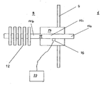
- a preferred embodiment of a measuring device 2 according to the invention is shown, which is arranged in a partition wall 4 between a process chamber 6 and the external environment 8.
- the process space 6, which is substantially closed may be, for example, the interior of a furnace for heating moist material such as e.g. Act food. Nevertheless, it is also conceivable to use any desired chemical processes in the process space 6, where the humidity of a gas present in the process space 6 plays a role, wherein a temperature range above the external ambient temperature is always relevant.
- the measuring device 2 has a so-called heat pipe 10, which extends with its first section 10a into the process space 6 and is located with its opposite second section 10b in the external environment 8.
- the heat pipe 10 which is also referred to as a "heat pipe”
- a liquid working fluid is circulated on the hot side, present in the first section 10 a, evaporated and condensed on the cold side, in the present case in the second section 10 b.
- the heat pipe 10 has an inner capillary structure, so that due to the capillary forces, the condensate is transported back. The finer the capillary structure, the greater the capillary forces.
- the choice of working fluid in the heat pipe depends on the temperature range in which heat is transferred.
- the heat pipe 10 uses the physical effect that quite large amounts of energy can be converted when evaporating and condensing a liquid. Since the heat pipe 10 is a known component, an illustration of the internal structure in the accompanying figure has been omitted.
- a heat sink 12 is disposed on the second portion 10 b of the heat pipe 10. Since, due to its high effect, the heat pipe 10 usually only needs to be designed in a small design and therefore preferably its diameter can be in a range of 3 mm, the energy to be absorbed by the heat pipe 10 is relatively low, so that one can make do with a small heat sink 12 , In most cases, however, the heat sink 12 can be completely dispensed with.
- the heat pipe 10 is provided at a portion 10 c, with which it extends through the partition wall 4, with a heat insulating body 14, which thermally insulated the heat pipe 10 of the partition wall 4.
- a temperature sensor 16 is provided, which is mounted directly on the lateral surface of the heat pipe 10 in the illustrated embodiment.
- the temperature sensor 16 is located inside the heat insulation body 14 outside the process space 6 in the area of the external environment 8.
- the temperature sensor 16 it is also conceivable to arrange the temperature sensor 16 at any other location provided that it correctly detects the temperature of the heat pipe 10. because the heat pipe 10 has substantially the same temperature over its entire length. Because of this substantially ideal temperature distribution of the heat pipe 10, in particular an arrangement of the temperature sensor 16 outside of the process chamber 6 and thus outside the usually prevailing harsh conditions is advantageous, the temperature sensor 16 nevertheless prevails at the lying in the process chamber 6 first portion 10a of the heat pipe 10 Temperature detected correctly.
- the temperature sensor 16 Due to the almost lossless heat transfer through the heat pipe 10, the temperature sensor 16 thus measures a temperature which corresponds to the temperature prevailing at the first section 10 a of the heat pipe 10. Because of the heat dissipation caused by the heat pipe 10, the temperature at the first section 10a drops to the dew point of the gas in the process chamber 6, so that the gas condenses at the first section 10a. Accordingly, the forms first section 10a of the heat pipe 10 a measuring point for the dew point, and the temperature sensor 16 measures a temperature value corresponding to the temperature at the first portion 10a in the process space 6 and represents the dew point of the gas located there.
- an evaluation device 20 shown only schematically in the figure is connected, which determines, for example from the temperature measured by the temperature sensor 16, the instantaneous moisture of the gas in the process chamber 6. At the beginning of a process, the evaluation should take place only when the temperature measured by the temperature sensor 16 substantially does not drop any further. Because the energy originally used for the cooling after the formation of dew on the first portion 10a of the heat pipe 10 in the process chamber 6 is then required for the condensation and maintenance of dew formation, with the result that despite continued heat dissipation, the temperature at the first portion 10a of Heat pipe essentially does not sink further.
Landscapes
- Physics & Mathematics (AREA)
- Health & Medical Sciences (AREA)
- Life Sciences & Earth Sciences (AREA)
- Chemical & Material Sciences (AREA)
- Analytical Chemistry (AREA)
- Biochemistry (AREA)
- General Health & Medical Sciences (AREA)
- General Physics & Mathematics (AREA)
- Immunology (AREA)
- Pathology (AREA)
- Investigating Or Analyzing Materials Using Thermal Means (AREA)
- Sampling And Sample Adjustment (AREA)
Description
- Die Erfindung betrifft eine Vorrichtung zur Messung der Kondensationstemperatur eines Gases an einer Messstelle, mit einem die Messstelle enthaltenden, durch eine Wand im wesentlichen geschlossenen Prozessraum zur Aufnahme des Gases, mit einer Wärmeableiteinrichtung zur Ableitung von Wärme aus dem Prozessraum derart, dass an der Messstelle die Temperatur des Gases auf den Taupunkt absinkt, und mit einem Temperatursensor. Ferner betrifft die Erfindung die Verwendung eines Wärmerohres und eines Temperatursensors zur Messung der Kondensationstemperatur eines Gases an einer Messstelle.
- Im Stand der Technik sind Vorrichtungen zur Messung der Kondensationstemperatur eines Gases bekannt, deren häufigster Verwendungszweck in der Ermittlung der Feuchtigkeit des Gases liegt.
- Beispielsweise offenbart die
EP 0 567 813 A1 eine Vorrichtung der eingangs genannten Art, bei welcher die Wärmeableiteinrichtung einen wärmeleitfähigen massiven Metallkörper aufweist, der in die den Prozessraum begrenzenden Wand eingesetzt und thermisch von dieser isoliert ist. Dabei ragt dieser Metallkörper mit seinem einen Ende in den Prozessraum und befindet sich mit seinem anderen Ende außerhalb des Prozessraumes. Es sind drei Temperatursensoren vorgesehen, von denen ein erster Temperatursensor mit dem im Prozessraum befindlichen ersten Ende des Metallkörpers und ein zweiter Temperatursensor mit dem zweiten Ende des Metallkörpers verbunden und ein dritter Temperatursensor entfernt vom Metallkörper in den Prozessraum eingesetzt ist. Der erste Temperaturfüller ermittelt den Taupunkt des Gases im Prozessraum am ersten Ende des Metallkörpers, während der zweite Temperatursensor die Temperatur am außerhalb des Prozessraumes liegenden zweiten Ende des Metallkörpers und der dritte Temperatursensor die im Prozessraum herrschende Temperatur misst. Die drei Temperatursensoren sind an eine Auswerteeinrichtung angeschlossen, in der kodierte Informationen gespeichert sind, die dem Temperaturbereich entsprechen, welche an den ersten und zweiten Enden des Metallkörpers und im Kochraum erreicht werden kann, und die auf der Grundlage der drei gemessenen Temperaturen und unter Verwendung der gespeicherten kodierten Informationen den Feuchtigkeitsgehalt des Gases im Prozessraum bestimmt. Ferner ist für die Ableitung der durch den Metallkörper geleiteten Wärme eine Kühleinrichtung zur Kühlung des außerhalb des Prozessraumes liegenden zweiten Endes des Metallkörpers vorgesehen, welche beispielsweise einen Kühlkörper, einen Lüfter und/oder ein ein flüssiges Kühlmedium enthaltendes Kühlelement aufweisen kann. Für die Bestimmung des Feuchtigkeitsgehaltes des Gases durch die Auswerteeinrichtung ist in diesem Zusammenhang die Messung der Temperatur am zweiten Ende des Metallkörpers durch den zweiten Temperatursensor von Bedeutung, weil im Metallkörper von dessen erstem Ende zu dessen zweitem Ende ein Temperaturabfall zu beobachten ist, der im wesentlichen zum einen von den Materialeigenschaften des Metallkörpers und zum anderen von der Wirkung der Kühleinrichtung bestimmt wird. Dieser aufgrund physikalischer Gegebenheiten unvermeintliche Temperaturabfall ist von Nachteil hinsichtlich Aufbau und Wirkungsweise der bekannten Vorrichtung. Denn der Temperaturabfall hat grundsätzlich negative Auswirkungen auf die Genauigkeit des Ergebnisses bei der Bestimmung des Feuchtigkeitsgehaltes. Dieser nachteilige Effekt kann zwar zumindest teilweise durch die Verwendung der drei beschriebenen Temperatursensoren ausglichen werden; jedoch bedingt deren Anordnung einen erhöhten konstruktiven Aufwand, was insbesondere zu höheren Kosten bei der Herstellung und für die Wartung der bekannten Vorrichtung führt, eine stärkere Anfälligkeit im Betrieb insbesondere bei den innerhalb des Prozessraumes angeordneten Temperatursensoren sowie eine kompliziertere Auswertung für die Bestimmung des Feuchtigkeitsgehaltes. - Die bekannte Vorrichtung findet hauptsächlich Verwendung in einem Backofen für Lebensmittel, um die Kondensationstemperatur bzw. den Taupunkt des Wasserdampfes als Funktion des Feuchtigkeitsgehaltes der Luft im Ofenraum zu bestimmen.
- Es ist Aufgabe der vorliegenden Erfindung, eine Vorrichtung der eingangs genannten Art mit einer einfacheren, kostengünstigeren und weniger anfälligen Konstruktion zu schaffen, die eine unkomplizierte und gleichwohl genaue Ermittlung der Kondensationstemperatur eines Gases ermöglicht.
- Zur Lösung dieser Aufgabe wird gemäß einem ersten Aspekt der Erfindung vorgeschlagen eine Vorrichtung zur Messung der Kondensationstemperatur eines Gases an einer Messstelle, mit einem die Messstelle enthaltenden, durch eine Wand im wesentlichen geschlossenen Prozessraum zur Aufnahme des Gases, mit einer Wärmeableiteinrichtung zur Ableitung von Wärme aus dem Prozessraum derart, dass an der Messstelle die Temperatur des Gases auf den Taupunkt absinkt, und mit einem Temperatursensor, dadurch gekennzeichnet, dass die Wärmeableiteinrichtung ein Wärmerohr aufweist, das mit einem ersten Abschnitt im Prozessraum und mit einem zweiten Abschnitt außerhalb des Prozessraumes angeordnet ist, und der Temperatursensor zur Messung der Temperatur im zweiten Abschnitt des Wärmerohres vorgesehen ist.
- Ferner wird gemäß einem zweiten Aspekt der vorliegenden Erfindung vorgeschlagen die Verwendung eines Wärmerohres und eines Temperatursensors zur Messung der Kondensationstemperatur eines Gases an einer Messstelle, dadurch gekennzeichnet, dass das Wärmerohr mit einem ersten Abschnitt innerhalb eines das Gas und die Messstelle enthaltenden und durch eine Wand im wesentlichen geschlossenen Prozessraumes und mit einem zweiten Abschnitt außerhalb des Prozessraumes positioniert und so ausgebildet ist, dass es aus dem Prozessraum Wärme derart ableitet, dass an der Messstelle die Temperatur des Gases auf den Taupunkt absinkt, und der Temperatursensor zur Messung der im Wärmerohr herrschenden Temperatur vorgesehen ist.
- Gegenüber dem zuvor erörterten Stand der Technik wird der dort verwendete massive Metallkörper erfindungsgemäß durch ein sog. Wärmerohr ersetzt. Bei einem Wärmerohr, das alternativ auch häufig als "Heatpipe" bezeichnet wird, handelt es sich um ein an sich bekanntes Bauteil, in dem ein flüssiges Arbeitsmedium einem Kreislauf unterworfen wird und nach Art einer Wärmepumpe nacheinander verdampft und wieder kondensiert, um Wärme sehr effizient von einem Ort zu einem anderen zu transportieren. Durch Verwendung eines solchen Wärmerohres nutzt demnach die Erfindung den physikalischen Effekt, dass beim Verdampfen und Kondensieren eines flüssigen Mediums sehr hohe Energiemengen ohne wesentliche Verluste umgesetzt werden. Dadurch ist es möglich, die Wärme von der Messstelle im Prozessraum im wesentlichen verlustfrei aus dem Prozessraum herauszuleiten, so dass das Wärmerohr über seine gesamte Länge im wesentlichen die gleiche Temperatur aufweist. Dadurch wird im Gegensatz zum Stand der Technik im wesentlichen nur noch ein einziger Temperatursensor benötigt, der eine Temperatur misst, die der auf den Taupunkt abgesenkten Temperatur des Gases im Prozessraum an der Messstelle entspricht. Somit ist die Messung der Temperatur im Prozessraum nicht mehr vonnöten, so dass auf die Anordnung eines weiteren Temperatursensors im Prozessraum verzichtet werden kann und somit negative Einflüsse auf die Funktion und Lebensdauer des Temperatursensors aufgrund der im Prozessraum gewöhnlich herrschenden recht rauen Bedingungen ausgeschlossen sind. Die im wesentlichen ideale Temperaturverteilung des Wärmerohres macht aber nicht nur eine Messung des im Prozessraum liegenden ersten Abschnittes des Wärmerohres, sondern auch eine Messung der im Prozessraum herrschenden normalen Temperatur entfernt vom Wärmerohr überflüssig. Neben der Verwendung nur eines einzigen Temperatursensors besteht ein weiterer Vorteil der Verwendung eines Wärmerohres darin, dass aufgrund seiner Fähigkeit, sehr hohe Energiemengen umsetzen zu können, in den meisten Fällen auch auf eine Kühleinrichtung verzichtet werden kann. Da ein Wärmerohr eine etwa 100- bis 1000-fach höhere Wärmemenge als ein Bauteil gleicher geometrischer Abmessungen aus massivem Kupfer transportieren kann, führt schließlich die Verwendung eines Wärmerohres zu einer vorteilhaften Verringerung der Baugröße der Vorrichtung. Dabei ist herausgefunden worden, dass das Wärmerohr bei der erfindungsgemäßen Anwendung gewöhnlich nur einen Durchmesser von wenigen Millimetern aufzuweisen braucht, wodurch sich die aufgenommene Energie reduziert und nicht zuletzt deshalb auf die Anordnung einer Kühleinrichtung in den meisten Fällen verzichtet werden kann.
- Die erfindungsgemäße Vorrichtung kann beispielsweise in einem Backofen verwendet werden, um den Wasserdampfgehalt der Luft im Ofenraum zu bestimmen, und zwar für Temperaturen, die oberhalb der Umgebungstemperatur liegen. Dennoch kann die erfindungsgemäße Vorrichtung in beliebigen anderen chemischen Prozessen Anwendung finden und die mit der erfindungsgemäßen Vorrichtung gewonnenen Messergebnisse nicht nur zur Ermittlung zur Feuchtigkeit eines Gases, sondern grundsätzlich auch zur Bestimmung von anderen Parametern eines Gases verwendet werden.
- Zwar schlägt die
EP 0 276 953 A2 vor, ein Wärmerohr zur Wärmeableitung sowie einen einzigen Temperatursensor zu verwenden, jedoch ist dieser Temperatursensor innerhalb der Kammer angeordnet. - Bevorzugte Ausführungen und Weiterbildungen der Erfindung sind in den abhängigen Ansprüchen angegeben.
- Zweckmäßigerweise sitzt der Temperatursensor im wesentlichen direkt am Wärmerohr.
- Wie zuvor ausgeführt, kann aufgrund der hohen Wirkungsweise des Wärmerohres in den meisten Fällen auf eine Kühleinrichtung verzichtet werden. Sollte dennoch eine Kühleinrichtung vonnöten sein, so ist diese zur Kühlung des zweiten Abschnittes des Wärmerohres außerhalb des Prozessraumes vorzusehen, wobei in derartigen Fällen gewöhnlich die Kühleinrichtung nur eine relativ geringe Leistung haben muss, da sie ja lediglich unterstützend wirkt, wodurch sie nur eine kleine Bauform benötigt. Die Kühleinrichtung kann mindestens einen am zweiten Abschnitt des Wärmerohres angeordneten Kühlkörper und/oder mindestens einen Lüfter aufweisen.
- Zweckmäßigerweise ist das Wärmerohr an einem Abschnitt, mit dem es in der Wand des Prozessraumes positionierbar ist und sich somit durch die Wand erstreckt, mit einem Wärmeisolationskörper versehen, der eine thermische Isolierung zwischen der Wand und dem Wärmerohr herstellt.
- Schließlich kann beispielsweise eine Auswerteeinrichtung vorgesehen sein, um die Feuchtigkeit des Gases im Prozessraum aus der vom Temperatursensor gemessenen Temperatur zu ermitteln. Insbesondere zu Beginn eines Prozesses sollte eine Auswertung erst dann stattfinden, wenn die vom Temperatursensor gemessene Temperatur im wesentlichen nicht weiter sinkt. Hierzu wird die Erkenntnis genutzt, dass die ursprünglich für die Kühlung verwendete Energie nach der Entstehung von Tau an der Messstelle nun für die Kondensation und Aufrechterhaltung der Taubildung benötigt wird, was zur Folge hat, dass dann trotzt fortgesetzter Wärmeableitung die Temperatur an dem von der Messstelle gebildeten Ort der Taubildung im wesentlichen nicht weiter sinkt.
- Nachfolgend wird die Erfindung anhand eines bevorzugten Ausführungsbeispiels näher erläutert, das in der beigefügten einzigen Figur schematisch dargestellt ist.
- In der beigefügten einzigen Figur ist ein bevorzugtes Ausführungsbeispiel einer erfindungsgemäßen Messvorrichtung 2 gezeigt, die in einer Trennwand 4 zwischen einem Prozessraum 6 und der äußeren Umgebung 8 angeordnet ist. Beim Prozessraum 6, der im wesentlichen geschlossen ist, kann es sich beispielsweise um den Innenraum eines Ofens zur Erhitzung von feuchtem Gut wie z.B. Lebensmitteln handeln. Gleichwohl ist aber auch die Anwendung beliebiger chemischer Prozesse im Prozessraum 6 denkbar, wo die Feuchtigkeit eines im Prozessraum 6 befindlichen Gases eine Rolle spielt, wobei stets ein Temperaturbereich oberhalb der äußeren Umgebungstemperatur relevant ist.
- Die Messvorrichtung 2 weist ein sog. Wärmerohr 10 auf, das sich mit ihrem ersten Abschnitt 10a in den Prozessraum 6 erstreckt und mit ihrem gegenüberliegenden zweiten Abschnitt 10b in der äußeren Umgebung 8 befindet. Im Wärmerohr 10, das auch als "Heatpipe" bezeichnet wird, wird ein flüssiges Arbeitsmittel im Kreislauf geführt, das an der heißen Seite, vorliegend im ersten Abschnitt 10a, verdampft und an der kalten Seite, vorliegend im zweiten Abschnitt 10b, kondensiert. Das Wärmerohr 10 weist eine innere kapillare Struktur auf, so dass aufgrund der Kapillarkräfte das Kondensat zurücktransportiert wird. Je feiner die Kapillarstruktur ist, desto größer sind die Kapillarkräfte. Die Wahl des Arbeitsmittels im Wärmerohr richtet sich nach dem Temperaturbereich, in dem Wärme transferiert wird. Gewöhnlich herrscht im Wärmerohr 10 ein Unterdruck, so dass das Arbeitsmittel bereits bei niedrigen Temperaturen verdampft. Somit nutzt das Wärmerohr 10 den physikalischen Effekt, dass beim Verdampfen und Kondensieren einer Flüssigkeit recht hohe Energiemengen umgesetzt werden können. Da es sich beim Wärmerohr 10 um ein bekanntes Bauteil handelt, ist auf eine Darstellung der inneren Struktur in der beiliegenden Figur verzichtet worden.
- Im dargestellten Ausführungsbeispiel ist ein Kühlkörper 12 am zweiten Abschnitt 10b des Wärmerohres 10 angeordnet. Da aufgrund seiner hohen Wirkung das Wärmerohr 10 gewöhnlich nur in einer geringen Bauform ausgeführt zu werden braucht und vorzugsweise dessen Durchmesser deshalb in einem Bereich von 3mm liegen kann, ist die vom Wärmerohr 10 aufzunehmende Energie relativ niedrig, so dass man mit einem kleinen Kühlkörper 12 auskommt. In den meisten Fällen kann aber auch auf den Kühlkörper 12 gänzlich verzichtet werden.
- Ferner ist das Wärmerohr 10 an einem Abschnitt 10c, mit dem es sich durch die Trennwand 4 erstreckt, mit einem Wärmeisolationskörper 14 versehen, der das Wärmerohr 10 von der Trennwand 4 thermisch isoliert.
- Schließlich ist ein Temperatursensor 16 vorgesehen, der im dargestellten Ausführungsbeispiel direkt auf der Mantelfläche des Wärmerohres 10 angebracht ist. Dabei sitzt der Temperatursensor 16 im dargestellten Ausführungsbeispiel innerhalb des Wärmeisolationskörpers 14 außerhalb des Prozessraumes 6 im Bereich der äußeren Umgebung 8. Es ist aber auch grundsätzlich denkbar, den Temperatursensor 16 an jeder beliebigen anderen Stelle anzuordnen, sofern er die Temperatur des Wärmerohres 10 korrekt erfasst, da das Wärmerohr 10 über seine gesamte Länge im wesentlichen die gleiche Temperatur hat. Wegen dieser im wesentlichen idealen Temperaturverteilung des Wärmerohres 10 ist insbesondere eine Anordnung des Temperatursensors 16 außerhalb des Prozessraumes 6 und somit außerhalb der gewöhnlich dort herrschenden rauen Bedingungen vorteilhaft, wobei der Temperatursensor 16 gleichwohl die an dem im Prozessraum 6 liegenden ersten Abschnitt 10a des Wärmerohres 10 herrschende Temperatur korrekt erfasst.
- Aufgrund der nahezu verlustlosen Wärmeübertragung durch das Wärmerohr 10 misst somit der Temperatursensor 16 eine Temperatur, die der am ersten Abschnitt 10a des Wärmerohres 10 herrschenden Temperatur entspricht. Wegen der vom Wärmerohr 10 bewirkten Wärmeableitung sinkt die Temperatur am ersten Abschnitt 10a auf den Taupunkt des im Prozessraum 6 befindlichen Gases, so dass am ersten Abschnitt 10a das Gas kondensiert. Demnach bildet der erste Abschnitt 10a des Wärmerohres 10 eine Messstelle für den Taupunkt, und der Temperatursensor 16 misst einen Temperaturwert, der der Temperatur am ersten Abschnitt 10a im Prozessraum 6 entspricht und den Taupunkt des dort befindlichen Gases repräsentiert.
- An den Temperatursensor 16 ist eine in der Figur nur schematisch dargestellte Auswerteeinrichtung 20 angeschlossen, die beispielsweise aus der vom Temperatursensor 16 gemessenen Temperatur die augenblickliche Feuchtigkeit des Gases im Prozessraum 6 ermittelt. Dabei sollte zu Beginn eines Prozesses die Auswertung erst dann stattfinden, wenn die vom Temperatursensor 16 gemessene Temperatur im wesentlichen nicht weiter sinkt. Denn die ursprünglich für die Kühlung verwendete Energie nach der Entstehung von Tau am ersten Abschnitt 10a des Wärmerohrs 10 im Prozessraum 6 wird dann für die Kondensation und Aufrechterhaltung der Taubildung benötigt, was zur Folge hat, dass trotz fortgesetzter Wärmeableitung die Temperatur am ersten Abschnitt 10a des Wärmerohres im wesentlichen nicht weiter absinkt.
Claims (15)
- Vorrichtung zur Messung der Kondensationstemperatur eines Gases an einer Messstelle, mit einem die Messstelle enthaltenden, durch eine Wand (4) im wesentlichen geschlossenen Prozessraum (6) zur Aufnahme des Gases, mit einer Wärmeableiteinrichtung (2), die mit einem ersten Abschnitt (10a) im Prozessraum (6) angeordnet und zur Ableitung von Wärme aus dem Prozessraum (6) derart ausgebildet ist, dass an der Messstelle die Temperatur des Gases auf den Taupunkt absinkt, und mit einem Temperatursensor (16), wobei die Wärmeableiteinrichtung (2) ein Wärmerohr (10) aufweist, das mit einem zweiten Abschnitt (10b) außerhalb des Prozessraumes (6) angeordnet ist, dadurch gekennzeichnet, dass der Temperatursensor (16) zur Messung der Temperatur im zweiten Abschnitt (10b) des Wärmerohres (10) vorgesehen ist.
- Vorrichtung nach Anspruch 1,
dadurch gekennzeichnet, dass der Temperatursensor (16) am zweiten Abschnitt (10b) des Wärmerohres (10) sitzt. - Vorrichtung nach mindestens einem der vorangegangenen Ansprüche,
gekennzeichnet durch eine Kühleinrichtung (12) zur Kühlung des zweiten Abschnittes (10b) des Wärmerohres (10). - Vorrichtung nach Anspruch 3,
dadurch gekennzeichnet, dass die Kühleinrichtung (12) mindestens einen am zweiten Abschnitt (10b) des Wärmerohres (10) angeordneten Kühlkörper aufweist. - Vorrichtung nach Anspruch 3 oder 4,
dadurch gekennzeichnet, dass die Kühleinrichtung mindestens einen Lüfter aufweist. - Vorrichtung nach mindestens einem der vorangegangenen Ansprüche,
dadurch gekennzeichnet, dass das Wärmerohr (10) an einem Abschnitt (10c), mit dem es in der Wand (4) des Prozessraumes (6) positionierbar ist, mit einem Wärmeisolationskörper (14) versehen ist. - Vorrichtung nach mindestens einem der vorangegangenen Ansprüche,
gekennzeichnet durch eine Auswerteeinrichtung (20) zur Ermittlung der Feuchtigkeit des Gases im Prozessraum (6) aus der vom Temperatursensor (16) gemessenen Temperatur. - Vorrichtung nach Anspruch 7,
dadurch gekennzeichnet, dass die Auswerteeinrichtung (20) zur Ermittlung der Feuchtigkeit des Gases im Prozessraum (6) aus der vom Temperatursensor (16) gemessenen Temperatur nach Feststellung, dass die vom Temperatursensor (18) gemessene Temperatur im Wesentlichen nicht weiter sinkt, eingerichtet ist. - Verwendung eines Wärmerohres und eines Temperatursensors zur Messung der Kondensationstemperatur eines Gases an einer Messstelle,
wobei das Wärmerohr (10) mit einem ersten Abschnitt (10a) innerhalb eines das Gas und die Messstelle enthaltenden und durch eine Wand (4) im Wesentlichen geschlossenen Prozessraumes (6) und mit einem zweiten Abschnitt (10b) außerhalb des Prozessraumes (6) positioniert und so ausgebildet ist, dass es aus dem Prozessraum (6) Wärme derart ableitet, dass an der Messstelle die Temperatur des Gases auf den Taupunkt absinkt, und der Temperatursensor (16) zur Messung der Temperatur im zweiten Abschnitt (10b) des Wärmerohres (10) vorgesehen ist. - Verwendung eines Wärmerohres und eines Temperatursensors zur Messung der Kondensationstemperatur eines Gases an einer Messstelle nach Anspruch 9,
dadurch gekennzeichnet, dass der Temperatursensor (16) am Wärmerohr (10) sitzt. - Verwendung eines Wärmerohres und eines Temperatursensors zur Messung der Kondensationstemperatur eines Gases an einer Messstelle nach Anspruch 10,
dadurch gekennzeichnet, dass der Temperatursensor (16) am zweiten Abschnitt (10b) des Wärmerohres (10) sitzt. - Verwendung eines Wärmerohres und eines Temperatursensors zur Messung der Kondensationstemperatur eines Gases an einer Messstelle nach mindestens einem der Ansprüche 9 bis 11,
dadurch gekennzeichnet, dass eine Kühleinrichtung (12) zur Kühlung des zweiten Abschnittes (10b) des Wärmerohres (10) vorgesehen ist. - Verwendung eines Wärmerohres und eines Temperatursensors zur Messung der Kondensationstemperatur eines Gases an einer Messstelle nach Anspruch 12,
dadurch gekennzeichnet, dass die Kühleinrichtung (12) mindestens einen am zweiten Abschnitt (10b) des Wärmerohres (10) angeordneten Kühlkörper aufweist. - Verwendung eines Wärmerohres und eines Temperatursensors zur Messung der Kondensationstemperatur eines Gases an einer Messstelle nach Anspruch 12 oder 13,
dadurch gekennzeichnet, dass die Kühleinrichtung mindestens einen Lüfter aufweist. - Verwendung eines Wärmerohres und eines Temperatursensors zur Messung der Kondensationstemperatur eines Gases an einer Messstelle nach mindestens einem der Ansprüche 9 bis 14,
dadurch gekennzeichnet, dass das Wärmerohr (10) an einem Abschnitt (10c), mit dem des in der Wand (4) des Prozessraumes (6) positionierbar ist, mit einem Wärmeisolationskörper (14) versehen ist.
Applications Claiming Priority (2)
| Application Number | Priority Date | Filing Date | Title |
|---|---|---|---|
| DE102005048756A DE102005048756A1 (de) | 2005-10-10 | 2005-10-10 | Vorrichtung zur Messung der Kondensationstemperatur eines Gases |
| PCT/EP2006/009526 WO2007042168A1 (de) | 2005-10-10 | 2006-10-02 | Vorrichtung zur messung der kondensationstemperatur eines gases |
Publications (2)
| Publication Number | Publication Date |
|---|---|
| EP1938092A1 EP1938092A1 (de) | 2008-07-02 |
| EP1938092B1 true EP1938092B1 (de) | 2011-07-06 |
Family
ID=37762450
Family Applications (1)
| Application Number | Title | Priority Date | Filing Date |
|---|---|---|---|
| EP06792348A Not-in-force EP1938092B1 (de) | 2005-10-10 | 2006-10-02 | Vorrichtung zur messung der kondensationstemperatur eines gases |
Country Status (5)
| Country | Link |
|---|---|
| EP (1) | EP1938092B1 (de) |
| AT (1) | ATE515691T1 (de) |
| DE (1) | DE102005048756A1 (de) |
| ES (1) | ES2367372T3 (de) |
| WO (1) | WO2007042168A1 (de) |
Cited By (2)
| Publication number | Priority date | Publication date | Assignee | Title |
|---|---|---|---|---|
| EP2136204A4 (de) * | 2007-04-04 | 2014-04-23 | Espec Corp | Hygrometer und taupunktinstrument |
| EP4001769A3 (de) * | 2020-11-24 | 2022-10-19 | Miele & Cie. KG | Gargerät mit einer kühlvorrichtung und kühlvorrichtung für ein gargerät |
Families Citing this family (5)
| Publication number | Priority date | Publication date | Assignee | Title |
|---|---|---|---|---|
| EP2467705B1 (de) | 2010-03-11 | 2014-12-03 | BARTEC BENKE GmbH | Vorrichtung und verfahren zum bestimmen des taupunktes eines gases |
| DE102010061472A1 (de) * | 2010-12-22 | 2012-06-28 | Miele & Cie. Kg | Gargerät |
| JP6027955B2 (ja) * | 2013-09-12 | 2016-11-16 | エスペック株式会社 | 湿度計構成部材、湿度計、および環境試験装置 |
| EP4112465B1 (de) | 2021-06-28 | 2025-02-19 | B/E Aerospace, Inc. | Kücheneinsatz mit ofen für die luftfahrt |
| CN114847748B (zh) * | 2022-06-02 | 2022-11-01 | 珠海格力电器股份有限公司 | 烹饪设备及烹饪设备清洁控制方法、装置、存储介质 |
Citations (1)
| Publication number | Priority date | Publication date | Assignee | Title |
|---|---|---|---|---|
| US4407353A (en) * | 1980-11-17 | 1983-10-04 | Snow Brand Milk Products Co., Ltd. | Waste heat recovery device for preventing corrosion by sulfur oxides |
Family Cites Families (4)
| Publication number | Priority date | Publication date | Assignee | Title |
|---|---|---|---|---|
| GB8701616D0 (en) | 1987-01-26 | 1987-03-04 | Michell Instr Ltd | Dewpoint meter |
| IT1258073B (it) | 1992-04-29 | 1996-02-20 | Zanussi Elettromecc | Dispositivo di misura dell'umidita' per forni, in particolare forni dicottura di alimenti |
| JP2001161556A (ja) * | 1999-12-08 | 2001-06-19 | Elco:Kk | 保温装置 |
| US7168850B2 (en) * | 2004-03-30 | 2007-01-30 | Yamatake Corporation | Mirror surface state detection device and moisture detection device |
-
2005
- 2005-10-10 DE DE102005048756A patent/DE102005048756A1/de not_active Withdrawn
-
2006
- 2006-10-02 ES ES06792348T patent/ES2367372T3/es active Active
- 2006-10-02 EP EP06792348A patent/EP1938092B1/de not_active Not-in-force
- 2006-10-02 WO PCT/EP2006/009526 patent/WO2007042168A1/de not_active Ceased
- 2006-10-02 AT AT06792348T patent/ATE515691T1/de active
Patent Citations (1)
| Publication number | Priority date | Publication date | Assignee | Title |
|---|---|---|---|---|
| US4407353A (en) * | 1980-11-17 | 1983-10-04 | Snow Brand Milk Products Co., Ltd. | Waste heat recovery device for preventing corrosion by sulfur oxides |
Cited By (4)
| Publication number | Priority date | Publication date | Assignee | Title |
|---|---|---|---|---|
| EP2136204A4 (de) * | 2007-04-04 | 2014-04-23 | Espec Corp | Hygrometer und taupunktinstrument |
| EP2894465A1 (de) * | 2007-04-04 | 2015-07-15 | Espec Corp. | Taupunktinstrument |
| EP3051279A1 (de) * | 2007-04-04 | 2016-08-03 | Espec Corp. | Hygrometer und taupunktinstrument |
| EP4001769A3 (de) * | 2020-11-24 | 2022-10-19 | Miele & Cie. KG | Gargerät mit einer kühlvorrichtung und kühlvorrichtung für ein gargerät |
Also Published As
| Publication number | Publication date |
|---|---|
| ES2367372T3 (es) | 2011-11-02 |
| EP1938092A1 (de) | 2008-07-02 |
| DE102005048756A1 (de) | 2007-04-12 |
| WO2007042168A1 (de) | 2007-04-19 |
| ATE515691T1 (de) | 2011-07-15 |
Similar Documents
| Publication | Publication Date | Title |
|---|---|---|
| DE69313507T2 (de) | Vorrichtung zur Messung der Feuchtigkeit, insbesondere in Nahrungsmittelöfen | |
| DE19638865A1 (de) | Kondensationswäschetrockner mit einer Wärmepumpeneinrichtung | |
| CH627275A5 (de) | ||
| EP1938092A1 (de) | Vorrichtung zur messung der kondensationstemperatur eines gases | |
| DE102009048248A1 (de) | Kühleinrichtung für einen bei erhöhter Umgebungstemperatur einsetzbaren Sensor | |
| DE19818627C5 (de) | Verfahren zum Konditionieren von Luft durch Einstellen der Temperatur und Luftfeuchtigkeit in einem Klimatisierungsschrank mittels eines Kältekreislaufs und Kältekreislauf | |
| DE102017105353A1 (de) | Hygrometer und Klimakammer | |
| EP2194370A1 (de) | Kondensationspartikelzähler | |
| DE102004055148B4 (de) | Vorrichtung für die Gefrier- oder Tieftemperatursubstitution | |
| DE8712814U1 (de) | Meßgaskühleinrichtung | |
| WO2021110430A1 (de) | Relativdrucksensor mit referenzdruckzuführung | |
| EP1624356B1 (de) | Vorrichtung zur Erzeugung von Referenzfeuchten | |
| EP2813782A1 (de) | Abschaltender Solarkollektor | |
| WO2015000526A1 (de) | Sensoreinheit | |
| EP4488598A1 (de) | Prüfkammer und verfahren zur steuerung | |
| EP3810999B1 (de) | Verfahren zum betrieb einer wärmepumpe und eine kältemaschine | |
| DE102005055773B4 (de) | Dampfgargerät zur Wärmebehandlung von Speisen | |
| EP2467705B1 (de) | Vorrichtung und verfahren zum bestimmen des taupunktes eines gases | |
| DE102008042285A1 (de) | Beheizbarer Zylinder zur Aufheizung einer Papier-, Karton-, Tissue- oder anderen Materialbahn | |
| DE102019124864A1 (de) | Temperaturüberwachung eines Wärmeleitsystems | |
| DE4232801A1 (de) | Ventil für Heizungs- oder Klimaanlagen | |
| WO2017137193A1 (de) | Hochspannungsvorrichtung | |
| DE3900943C1 (en) | Device for determining the thermal transfer between a quenching agent of a quenching device and a metallic workpiece | |
| WO2001081763A1 (de) | Messgaspumpe | |
| DE102004026181A1 (de) | Einrichtung zum Messen von Druck und Temperatur |
Legal Events
| Date | Code | Title | Description |
|---|---|---|---|
| PUAI | Public reference made under article 153(3) epc to a published international application that has entered the european phase |
Free format text: ORIGINAL CODE: 0009012 |
|
| 17P | Request for examination filed |
Effective date: 20080513 |
|
| AK | Designated contracting states |
Kind code of ref document: A1 Designated state(s): AT BE BG CH CY CZ DE DK EE ES FI FR GB GR HU IE IS IT LI LT LU LV MC NL PL PT RO SE SI SK TR |
|
| 17Q | First examination report despatched |
Effective date: 20080925 |
|
| DAX | Request for extension of the european patent (deleted) | ||
| GRAP | Despatch of communication of intention to grant a patent |
Free format text: ORIGINAL CODE: EPIDOSNIGR1 |
|
| GRAS | Grant fee paid |
Free format text: ORIGINAL CODE: EPIDOSNIGR3 |
|
| GRAA | (expected) grant |
Free format text: ORIGINAL CODE: 0009210 |
|
| AK | Designated contracting states |
Kind code of ref document: B1 Designated state(s): AT BE BG CH CY CZ DE DK EE ES FI FR GB GR HU IE IS IT LI LT LU LV MC NL PL PT RO SE SI SK TR |
|
| REG | Reference to a national code |
Ref country code: GB Ref legal event code: FG4D Free format text: NOT ENGLISH |
|
| REG | Reference to a national code |
Ref country code: CH Ref legal event code: EP |
|
| REG | Reference to a national code |
Ref country code: IE Ref legal event code: FG4D Free format text: LANGUAGE OF EP DOCUMENT: GERMAN |
|
| REG | Reference to a national code |
Ref country code: CH Ref legal event code: NV Representative=s name: RENTSCH PARTNER AG |
|
| REG | Reference to a national code |
Ref country code: DE Ref legal event code: R096 Ref document number: 502006009804 Country of ref document: DE Effective date: 20110825 |
|
| REG | Reference to a national code |
Ref country code: NL Ref legal event code: VDEP Effective date: 20110706 |
|
| REG | Reference to a national code |
Ref country code: ES Ref legal event code: FG2A Ref document number: 2367372 Country of ref document: ES Kind code of ref document: T3 Effective date: 20111102 |
|
| PG25 | Lapsed in a contracting state [announced via postgrant information from national office to epo] |
Ref country code: SI Free format text: LAPSE BECAUSE OF FAILURE TO SUBMIT A TRANSLATION OF THE DESCRIPTION OR TO PAY THE FEE WITHIN THE PRESCRIBED TIME-LIMIT Effective date: 20110706 |
|
| PG25 | Lapsed in a contracting state [announced via postgrant information from national office to epo] |
Ref country code: NL Free format text: LAPSE BECAUSE OF FAILURE TO SUBMIT A TRANSLATION OF THE DESCRIPTION OR TO PAY THE FEE WITHIN THE PRESCRIBED TIME-LIMIT Effective date: 20110706 Ref country code: IS Free format text: LAPSE BECAUSE OF FAILURE TO SUBMIT A TRANSLATION OF THE DESCRIPTION OR TO PAY THE FEE WITHIN THE PRESCRIBED TIME-LIMIT Effective date: 20111106 Ref country code: SE Free format text: LAPSE BECAUSE OF FAILURE TO SUBMIT A TRANSLATION OF THE DESCRIPTION OR TO PAY THE FEE WITHIN THE PRESCRIBED TIME-LIMIT Effective date: 20110706 Ref country code: LT Free format text: LAPSE BECAUSE OF FAILURE TO SUBMIT A TRANSLATION OF THE DESCRIPTION OR TO PAY THE FEE WITHIN THE PRESCRIBED TIME-LIMIT Effective date: 20110706 Ref country code: FI Free format text: LAPSE BECAUSE OF FAILURE TO SUBMIT A TRANSLATION OF THE DESCRIPTION OR TO PAY THE FEE WITHIN THE PRESCRIBED TIME-LIMIT Effective date: 20110706 Ref country code: PT Free format text: LAPSE BECAUSE OF FAILURE TO SUBMIT A TRANSLATION OF THE DESCRIPTION OR TO PAY THE FEE WITHIN THE PRESCRIBED TIME-LIMIT Effective date: 20111107 |
|
| REG | Reference to a national code |
Ref country code: IE Ref legal event code: FD4D |
|
| PG25 | Lapsed in a contracting state [announced via postgrant information from national office to epo] |
Ref country code: CY Free format text: LAPSE BECAUSE OF FAILURE TO SUBMIT A TRANSLATION OF THE DESCRIPTION OR TO PAY THE FEE WITHIN THE PRESCRIBED TIME-LIMIT Effective date: 20110706 Ref country code: PL Free format text: LAPSE BECAUSE OF FAILURE TO SUBMIT A TRANSLATION OF THE DESCRIPTION OR TO PAY THE FEE WITHIN THE PRESCRIBED TIME-LIMIT Effective date: 20110706 Ref country code: LV Free format text: LAPSE BECAUSE OF FAILURE TO SUBMIT A TRANSLATION OF THE DESCRIPTION OR TO PAY THE FEE WITHIN THE PRESCRIBED TIME-LIMIT Effective date: 20110706 Ref country code: GR Free format text: LAPSE BECAUSE OF FAILURE TO SUBMIT A TRANSLATION OF THE DESCRIPTION OR TO PAY THE FEE WITHIN THE PRESCRIBED TIME-LIMIT Effective date: 20111007 |
|
| BERE | Be: lapsed |
Owner name: VERETA G.M.B.H. Effective date: 20111031 |
|
| PG25 | Lapsed in a contracting state [announced via postgrant information from national office to epo] |
Ref country code: IE Free format text: LAPSE BECAUSE OF FAILURE TO SUBMIT A TRANSLATION OF THE DESCRIPTION OR TO PAY THE FEE WITHIN THE PRESCRIBED TIME-LIMIT Effective date: 20110706 Ref country code: CZ Free format text: LAPSE BECAUSE OF FAILURE TO SUBMIT A TRANSLATION OF THE DESCRIPTION OR TO PAY THE FEE WITHIN THE PRESCRIBED TIME-LIMIT Effective date: 20110706 Ref country code: SK Free format text: LAPSE BECAUSE OF FAILURE TO SUBMIT A TRANSLATION OF THE DESCRIPTION OR TO PAY THE FEE WITHIN THE PRESCRIBED TIME-LIMIT Effective date: 20110706 |
|
| PLBE | No opposition filed within time limit |
Free format text: ORIGINAL CODE: 0009261 |
|
| STAA | Information on the status of an ep patent application or granted ep patent |
Free format text: STATUS: NO OPPOSITION FILED WITHIN TIME LIMIT |
|
| PG25 | Lapsed in a contracting state [announced via postgrant information from national office to epo] |
Ref country code: MC Free format text: LAPSE BECAUSE OF NON-PAYMENT OF DUE FEES Effective date: 20111031 Ref country code: RO Free format text: LAPSE BECAUSE OF FAILURE TO SUBMIT A TRANSLATION OF THE DESCRIPTION OR TO PAY THE FEE WITHIN THE PRESCRIBED TIME-LIMIT Effective date: 20110706 Ref country code: EE Free format text: LAPSE BECAUSE OF FAILURE TO SUBMIT A TRANSLATION OF THE DESCRIPTION OR TO PAY THE FEE WITHIN THE PRESCRIBED TIME-LIMIT Effective date: 20110706 |
|
| 26N | No opposition filed |
Effective date: 20120411 |
|
| PG25 | Lapsed in a contracting state [announced via postgrant information from national office to epo] |
Ref country code: DK Free format text: LAPSE BECAUSE OF FAILURE TO SUBMIT A TRANSLATION OF THE DESCRIPTION OR TO PAY THE FEE WITHIN THE PRESCRIBED TIME-LIMIT Effective date: 20110706 |
|
| PG25 | Lapsed in a contracting state [announced via postgrant information from national office to epo] |
Ref country code: BE Free format text: LAPSE BECAUSE OF NON-PAYMENT OF DUE FEES Effective date: 20111031 |
|
| REG | Reference to a national code |
Ref country code: DE Ref legal event code: R097 Ref document number: 502006009804 Country of ref document: DE Effective date: 20120411 |
|
| PG25 | Lapsed in a contracting state [announced via postgrant information from national office to epo] |
Ref country code: LU Free format text: LAPSE BECAUSE OF NON-PAYMENT OF DUE FEES Effective date: 20111002 |
|
| PG25 | Lapsed in a contracting state [announced via postgrant information from national office to epo] |
Ref country code: BG Free format text: LAPSE BECAUSE OF FAILURE TO SUBMIT A TRANSLATION OF THE DESCRIPTION OR TO PAY THE FEE WITHIN THE PRESCRIBED TIME-LIMIT Effective date: 20111006 |
|
| PG25 | Lapsed in a contracting state [announced via postgrant information from national office to epo] |
Ref country code: TR Free format text: LAPSE BECAUSE OF FAILURE TO SUBMIT A TRANSLATION OF THE DESCRIPTION OR TO PAY THE FEE WITHIN THE PRESCRIBED TIME-LIMIT Effective date: 20110706 |
|
| PG25 | Lapsed in a contracting state [announced via postgrant information from national office to epo] |
Ref country code: HU Free format text: LAPSE BECAUSE OF FAILURE TO SUBMIT A TRANSLATION OF THE DESCRIPTION OR TO PAY THE FEE WITHIN THE PRESCRIBED TIME-LIMIT Effective date: 20110706 |
|
| REG | Reference to a national code |
Ref country code: FR Ref legal event code: PLFP Year of fee payment: 10 |
|
| REG | Reference to a national code |
Ref country code: FR Ref legal event code: PLFP Year of fee payment: 11 |
|
| REG | Reference to a national code |
Ref country code: CH Ref legal event code: PCAR Free format text: NEW ADDRESS: BELLERIVESTRASSE 203 POSTFACH, 8034 ZUERICH (CH) |
|
| REG | Reference to a national code |
Ref country code: FR Ref legal event code: PLFP Year of fee payment: 12 |
|
| PGFP | Annual fee paid to national office [announced via postgrant information from national office to epo] |
Ref country code: FR Payment date: 20171023 Year of fee payment: 12 |
|
| PGFP | Annual fee paid to national office [announced via postgrant information from national office to epo] |
Ref country code: ES Payment date: 20171103 Year of fee payment: 12 Ref country code: IT Payment date: 20171020 Year of fee payment: 12 Ref country code: GB Payment date: 20171024 Year of fee payment: 12 Ref country code: AT Payment date: 20171018 Year of fee payment: 12 Ref country code: CH Payment date: 20171023 Year of fee payment: 12 |
|
| REG | Reference to a national code |
Ref country code: CH Ref legal event code: PL |
|
| REG | Reference to a national code |
Ref country code: AT Ref legal event code: MM01 Ref document number: 515691 Country of ref document: AT Kind code of ref document: T Effective date: 20181002 |
|
| GBPC | Gb: european patent ceased through non-payment of renewal fee |
Effective date: 20181002 |
|
| PG25 | Lapsed in a contracting state [announced via postgrant information from national office to epo] |
Ref country code: FR Free format text: LAPSE BECAUSE OF NON-PAYMENT OF DUE FEES Effective date: 20181031 Ref country code: CH Free format text: LAPSE BECAUSE OF NON-PAYMENT OF DUE FEES Effective date: 20181031 Ref country code: LI Free format text: LAPSE BECAUSE OF NON-PAYMENT OF DUE FEES Effective date: 20181031 |
|
| PG25 | Lapsed in a contracting state [announced via postgrant information from national office to epo] |
Ref country code: GB Free format text: LAPSE BECAUSE OF NON-PAYMENT OF DUE FEES Effective date: 20181002 Ref country code: AT Free format text: LAPSE BECAUSE OF NON-PAYMENT OF DUE FEES Effective date: 20181002 Ref country code: IT Free format text: LAPSE BECAUSE OF NON-PAYMENT OF DUE FEES Effective date: 20181002 |
|
| REG | Reference to a national code |
Ref country code: ES Ref legal event code: FD2A Effective date: 20191129 |
|
| PG25 | Lapsed in a contracting state [announced via postgrant information from national office to epo] |
Ref country code: ES Free format text: LAPSE BECAUSE OF NON-PAYMENT OF DUE FEES Effective date: 20181003 |
|
| PGFP | Annual fee paid to national office [announced via postgrant information from national office to epo] |
Ref country code: DE Payment date: 20201105 Year of fee payment: 15 |
|
| REG | Reference to a national code |
Ref country code: DE Ref legal event code: R119 Ref document number: 502006009804 Country of ref document: DE |
|
| PG25 | Lapsed in a contracting state [announced via postgrant information from national office to epo] |
Ref country code: DE Free format text: LAPSE BECAUSE OF NON-PAYMENT OF DUE FEES Effective date: 20220503 |