EP1938010B1 - Wasserhahn mit kugelförmigem drehverschluss - Google Patents
Wasserhahn mit kugelförmigem drehverschluss Download PDFInfo
- Publication number
- EP1938010B1 EP1938010B1 EP06808198A EP06808198A EP1938010B1 EP 1938010 B1 EP1938010 B1 EP 1938010B1 EP 06808198 A EP06808198 A EP 06808198A EP 06808198 A EP06808198 A EP 06808198A EP 1938010 B1 EP1938010 B1 EP 1938010B1
- Authority
- EP
- European Patent Office
- Prior art keywords
- upstream
- axis
- obturator
- seat
- duct
- Prior art date
- Legal status (The legal status is an assumption and is not a legal conclusion. Google has not performed a legal analysis and makes no representation as to the accuracy of the status listed.)
- Active
Links
- 238000011144 upstream manufacturing Methods 0.000 claims abstract description 143
- 239000012530 fluid Substances 0.000 claims description 22
- 230000000712 assembly Effects 0.000 claims description 8
- 238000000429 assembly Methods 0.000 claims description 8
- 238000007789 sealing Methods 0.000 claims description 7
- 238000006073 displacement reaction Methods 0.000 claims description 2
- 230000000903 blocking effect Effects 0.000 claims 6
- 239000012528 membrane Substances 0.000 description 7
- 208000031968 Cadaver Diseases 0.000 description 6
- 230000000694 effects Effects 0.000 description 5
- 241000287107 Passer Species 0.000 description 2
- 230000002457 bidirectional effect Effects 0.000 description 2
- 238000007747 plating Methods 0.000 description 2
- 206010010904 Convulsion Diseases 0.000 description 1
- 241000897276 Termes Species 0.000 description 1
- 239000002184 metal Substances 0.000 description 1
Images


Classifications
-
- F—MECHANICAL ENGINEERING; LIGHTING; HEATING; WEAPONS; BLASTING
- F16—ENGINEERING ELEMENTS AND UNITS; GENERAL MEASURES FOR PRODUCING AND MAINTAINING EFFECTIVE FUNCTIONING OF MACHINES OR INSTALLATIONS; THERMAL INSULATION IN GENERAL
- F16K—VALVES; TAPS; COCKS; ACTUATING-FLOATS; DEVICES FOR VENTING OR AERATING
- F16K5/00—Plug valves; Taps or cocks comprising only cut-off apparatus having at least one of the sealing faces shaped as a more or less complete surface of a solid of revolution, the opening and closing movement being predominantly rotary
- F16K5/06—Plug valves; Taps or cocks comprising only cut-off apparatus having at least one of the sealing faces shaped as a more or less complete surface of a solid of revolution, the opening and closing movement being predominantly rotary with plugs having spherical surfaces; Packings therefor
- F16K5/0663—Packings
- F16K5/0673—Composite packings
-
- F—MECHANICAL ENGINEERING; LIGHTING; HEATING; WEAPONS; BLASTING
- F16—ENGINEERING ELEMENTS AND UNITS; GENERAL MEASURES FOR PRODUCING AND MAINTAINING EFFECTIVE FUNCTIONING OF MACHINES OR INSTALLATIONS; THERMAL INSULATION IN GENERAL
- F16K—VALVES; TAPS; COCKS; ACTUATING-FLOATS; DEVICES FOR VENTING OR AERATING
- F16K5/00—Plug valves; Taps or cocks comprising only cut-off apparatus having at least one of the sealing faces shaped as a more or less complete surface of a solid of revolution, the opening and closing movement being predominantly rotary
- F16K5/08—Details
- F16K5/14—Special arrangements for separating the sealing faces or for pressing them together
- F16K5/20—Special arrangements for separating the sealing faces or for pressing them together for plugs with spherical surfaces
- F16K5/205—Sealing effected by the flowing medium
Definitions
- the present invention relates to a ball valve.
- Such a valve conventionally comprises a body in which is formed a channel, and a spherical shutter which, mounted in the body pivotally about an axis perpendicular to the axis of the channel, has a through hole allowing the passage of fluid between an upstream pipe and a downstream pipe, in the open position.
- an upstream seat is generally mounted in the body channel upstream of the shutter, movably in translation along the axis of the channel of the body. The upstream seat is intended to seal the valve in the closed position, being pressed against the shutter.
- valves are not suitable for uses at low or medium pressures because in this case, the veneer of the upstream seat against the shutter by the pressure of the upstream pipe is insufficient to ensure satisfactory sealing of the valve in the closed position .
- the realization of this seal is also hindered by the presence of springs tending to move the upstream seat shutter.
- the present invention aims to overcome the drawbacks mentioned above, by providing a valve usable throughout the range of pressures (low, medium and high pressures), which has improved sealing while being easily manoeuvrable without risk of seizure.
- the invention relates to a tap according to claim 1.
- the upstream seat in its most downstream position since the boss is housed in the recess. Sealing is ensured by the action of the elastic means and the fluid pressure upstream (the relative importance of these two forces depending on the pressure of use of the valve), which tend to press the upstream seat against the shutter.
- the boss may be formed of a roller rotatably mounted about an axis integral with the upstream seat and substantially parallel to the axis of pivoting of the shutter, and / or be provided on a ring fixed on the downstream part of the upstream seat. substantially centered on the axis of the body channel.
- the upstream seat itself forms a crown.
- the shutter comprises a second recess located substantially at the same distance from the plane orthogonal to the axis of pivoting of the shutter passing through the axis of the through orifice as the first recess, said second recess being arranged to cooperate with the boss when the shutter is in the open position.
- the upstream seat is in its most downstream position since the boss is housed in the recess.
- the shutter comprises at least two assemblies each comprising a first recess or a first and a second recess, the two assemblies being substantially symmetrical to one another with respect to the plane orthogonal to the pivot axis of the shutter passing through the axis of the through orifice and the upstream seat comprises two bosses substantially symmetrical with respect to the axis of the channel of the body and located on a line substantially parallel to the axis of pivoting of the shutter , so that each boss can cooperate with the recess or recesses of one of the two sets.
- This symmetrical arrangement makes it possible to obtain a recoil of the upstream seat parallel to the axis of the channel of the body in avoiding a "cross" of the upstream seat in this channel, which could lead to the appearance of friction on the shutter during the pivoting of the latter.
- the shutter can comprise at least two assemblies each comprising a first recess or a first and a second recess, the two sets being substantially symmetrical to each other with respect to the axis of pivoting of the shutter .
- This provides a "bidirectional" valve, the recesses of an assembly cooperating with a boss formed on the downstream seat.
- the shutter can thus comprise four sets of one or two recesses each (on the upstream side / the downstream side and on either side of the axis of the body channel).
- the axis of the duct is substantially orthogonal to the axis of pivoting of the shutter and the cam comprises a part located opposite the bearing face of the obstruction means, a first end of which is fixed the body of the valve (or cap integral with the body) pivotally about an axis substantially parallel to the axis of pivoting of the shutter, and a second end has a boss projecting towards the actuating rod of the shutter, said boss being arranged to cooperate, when the valve is in closed and sealed position, with a cavity formed in the actuating rod.
- the valve 1 also comprises a shutter 6 rotating mounted in the body 2, by means of bearings 7, 8, pivotally about an axis 9 substantially perpendicular to the axis 3.
- the shutter 6 has a main portion spherical having a cylindrical through hole 10 of axis 11, the axis 11 being located in the plane orthogonal to the pivot axis 9 of the shutter 6 passing through the axis 3 of the channel of the body 2.
- the spherical main part the shutter 6 is extended by two cylindrical portions 12 of axis substantially coincident with the pivot axis 9 of the shutter 6, each extending on one side of the spherical main portion.
- the recesses have for example a semi-cylindrical shape with an axis substantially parallel to the axis of pivoting 9 of the shutter 6. Moreover, the four recesses formed in one of the cylindrical portions 12 and the four recesses formed in the other cylindrical portions 12 are substantially symmetrical to each other with respect to the plane orthogonal to the pivot axis 9 of the shutter 6 passing through the axis 11 of the through-orifice 10 of the shutter 6.
- An upstream seat 15 having a central passage 16 is mounted substantially coaxially in the channel of the body 2 upstream of the shutter 6, in a translationally movable manner along the axis 3, according to a limited amplitude.
- the upstream seat 15 From upstream to downstream, the upstream seat 15 comprises a first annular portion 17, a second annular portion 18 of larger external diameter, defining an abutment surface, a third annular portion 19 of even greater external diameter, and then a fourth annular portion 20 of outside diameter less than that of the third annular portion 19. These four annular portions have substantially the same internal diameter, so that the central passage 16 is substantially cylindrical.
- the upstream seat 15 comprises finally, the most downstream, a fifth annular portion 59 (delimiting the sealing surface of the upstream seat 15) of which the outside diameter is smaller than the outside diameter of the third annular portion 19 (and in this case substantially equal to the outside diameter of the fourth annular portion 20) and the inside diameter of which is greater than the outside diameter of the first annular portion 17. choice of these dimensions is explained later.
- the upstream seat 15 is mounted in the body 2 by means of an annular guide element 21, placed between the third annular portion 19 and the body 2, and an annular closure element 22 placed between the first annular portion 17 and the body 2. Seals 23, 24 are interposed between the body 2 and the guide member 21, respectively the closure member 22. In addition, segments 25 are placed between the closure member 22 and the upstream seat 15, a low radial clearance being formed between these two parts.
- an upstream annular chamber 26 which is in limited fluid communication with the central passage 16 of the upstream seat 15 via the segments 25 and the radial clearance supra.
- a spring washer 27 bearing on the one hand on the abutment surface formed between the first and second annular portions 17, 18 of the upstream seat 15 and on the other hand on a stop surface formed on the closure element 22. The washer 27 thus urges the upstream seat 15 towards the shutter 6, which has the effect of pressing the downstream end 28 of the upstream seat 15 against the shutter 6, and, consequently, sealing the valve 1 in the closed position of the shutter 6.
- a metal membrane 54 is further disposed in the upstream annular chamber 26 against the downstream face of this chamber, one end of the membrane 54 being fixed to the guide member 21 and the other end being fixed to the upstream seat 15.
- the membrane 54 seals between the upstream seat 15 and the body 2 when the valve is in closed and sealed position.
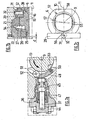
- a ring 29 is mounted on the fourth annular portion 20 of the upstream seat 15, in the channel of the body 2.
- the ring 29, illustrated on the figure 2 comprises two substantially parallelepipedal recesses 30, diametrically opposed, in each of which is mounted a roller 31, rotatably about the same axis 32 substantially joining the centers of the two recesses 30.
- the ring 29 is mounted on the upstream seat 15 of so that the axis 32 is substantially parallel to the pivot axis 9 of the shutter 6 and is secant with the axis 3 of the channel of the body 2.
- the rollers 31 are then each disposed facing a cylindrical portion 12 of the shutter 6, at the same axial level as the recesses 55, 56, 57, 58, and projecting towards the shutter 6 relative to the downstream end 28 of the seat upstream 15.
- a false downstream seat 33 having a central passage 34 is mounted inside the channel of the body 2, the downstream side of the shutter 6, with the interposition of a seal 35 to ensure continuity between the central passage 16 , the orifice 10 and the central passage 34.
- the false downstream seat 33 could have a structure similar to that of the upstream seat 15, in particular for the use of the valve 1 in the two directions of circulation of the fluid (direction of flow). arrow F and opposite direction).
- each of the two "upstream” and “downstream” seats is preferably equipped, in addition to the membrane 54, with a counter-membrane which, during the balancing phases, intervenes to protect the membrane associated with the seat on the "downstream” side against the effect of reverse pressure, which a simple membrane could not withstand.
- the upstream fluid duct, the central passage 16 of the upstream seat 15, the through-orifice 10 of the shutter 6, the central passage 34 of the downstream downstream seat 33 and the downstream fluid duct are substantially coaxial and from neighboring sections.
- valve 1 comprises means for balancing the pressure between the upstream and downstream of the upstream seat 15, prior to the opening of the valve 1, these means forming a bypass circuit.
- the balancing means firstly comprise a cylindrical duct 36 of axis 37 formed in the body 2 substantially orthogonal to the axis of pivoting 9 of the shutter 6 and to the axis 3 of the channel of the body 2
- the duct 36 comprises a first portion 38 having radial orifices 39 opening into a channel 40 pierced in the body 2 obliquely from the upstream annular chamber 26.
- the duct 36 also comprises a second portion 41 extending the first portion 38 in the direction of the actuating rod 13, and whose diameter is smaller than that of the first portion 38.
- the second portion 41 has radial orifices 42 opening into the central volume receiving the shutter 6, this volume forming, in closed and sealed position of the valve 1, a downstream annular chamber 43 located between the upstream seat 15 and the shutter 6 and not communicating with the central passage 16 of the upstream seat 15.
- the pressure equalization means furthermore comprise a cam 48 formed of a curved part linked to the cap 60, itself fixed to the body 2 of the valve 1 and whose convex outer face 49 is arranged opposite the face of the valve. 46 of the pusher 44.
- the cam 48 comprises a first end attached to the cap 60 rotatably about an axis 50 substantially parallel to the pivot axis 9 of the shutter 6 and a second end to which is fixed a roller 51, rotatably about an axis 52 substantially parallel to the axis 50.
- the roller 51 is arranged to cooperate, when the valve 1 is in closed and sealed position, with a cavity 53 formed in the actuating rod 13.
- the cavity 53 is spaced angularly from the axis 37 of the duct 36 by an angle 13 of the order of 20 °.
- the pivoting of the shutter 6 is thus facilitated by the fact that the friction against the upstream seat 15 is greatly reduced, because located only at the roller 31 and not over the entire contact surface between the upstream seat 15 and the spherical portion of the shutter 6.
- the valve 1 is in the intermediate open position ( Figures 6a, 6b, 6c ).
- the invention provides a decisive improvement to the prior art, providing a perfectly tight valve low or medium pressure and easily maneuverable.
Claims (10)
- Hahn, umfassend:- einen Körper (2), in dem ein Kanal mit einer Achse (3) eingerichtet ist, der dazu gedacht ist, zwischen einer vorgeschalteten Leitung und einer nachgeschalteten Leitung angeordnet zu werden;- einen im Wesentlichen sphärischen Drehverschluss (6), der in dem Körper um eine Achse (9), die zu der Achse (3) des Kanals im Wesentlichen rechtwinklig ist, zwischen einer geschlossenen Position und einer geöffneten Position schwenkbar angebracht ist, wobei der Verschluss (6) eine Durchgangsöffnung (10) mit einer Achse (11) umfasst, die dazu gedacht ist, in der geöffneten Position den Durchgang von Fluid von der vorgeschalteten Leitung in die nachgeschaltete Leitung zu erlauben;- einen vorgeschalteten Sitz (15), der einen mittleren Durchgang (16) aufweist, der in dem Kanal des Körpers (2) oberhalb des Verschlusses (6) translationsmäßig an der Achse (3) des Kanals des Körpers (2) entlang beweglich angebracht ist;- Mittel zum Ausgleichen des Fluiddrucks zwischen dem vorgeschalteten und dem nachgeschalteten Teil des vorgeschalteten Sitzes (15), vor dem Öffnen des Hahns (1);- elastische Mittel (27), die angeordnet sind, um den vorgeschalteten Sitz (15) zum Verschluss (6) hin vorzuspannen;
dadurch gekennzeichnet, dass er ferner Folgendes umfasst:- mindestens eine Erhebung (31), die auf dem vorgeschalteten Sitz (15) eingerichtet ist und im Wesentlichen parallel zur Achse (3) des Kanals des Körpers (2) in Richtung auf den Verschluss (6) vorsteht, und mindestens eine erste Ausnehmung (55, 56), die auf dem Verschluss (6) eingerichtet ist und angeordnet ist, um mit der Erhebung (31) zusammenzuwirken, wenn der Verschluss (6) sich in der geschlossenen Position befindet;- eine zweite Ausnehmung (56), die auf dem Verschluss (6) eingerichtet ist und angeordnet ist, um mit der Erhebung (31) zusammenzuwirken, wenn der Verschluss (6) sich in der geöffneten Position befindet, wobei die zweite Ausnehmung (56) sich im Wesentlichen von der Ebene, die zu der Schwenkachse (9) des Verschlusses (6) orthogonal ist, die durch die Achse (11) der Durchgangsöffnung (10) geht, in dem gleichen Abstand befindet wie die erste Ausnehmung (55), wobei die zweite Ausnehmung (56) sich im Wesentlichen in der Ebene befindet, die von der Schwenkachse (9) des Verschlusses (6) und der Achse (11) der Durchgangsöffnung (10) des Verschlusses (6) gebildet wird, wobei die erste Ausnehmung (55) winkelmäßig von der ersten Ausnehmung (56) um einen Winkel (α) zwischen 70° und 80° beabstandet ist. - Hahn nach Anspruch 1, dadurch gekennzeichnet, dass die Erhebung durch eine Rolle (31) gebildet wird, die um eine Achse (32), die mit dem nachgeschalteten Sitz (15) fest verbunden ist und zu der Schwenkachse (9) des Verschlusses (6) im Wesentlichen parallel ist, drehbar angebracht ist.
- Hahn nach Anspruch 1 oder 2, dadurch gekennzeichnet, dass die Erhebung (31) auf einem Kranz (29) eingerichtet ist, der auf dem nachgeschalteten Teil des vorgeschalteten Sitzes (15) befestigt ist, im Wesentlichen um die Achse (3) des Kanals des Körpers (2) zentriert, wobei die erste Ausnehmung (55) auf einem zylindrischen Teil (12) eingerichtet ist, der den sphärischen Hauptteil des Verschlusses (6) verlängert und dessen Achse im Wesentlichen mit der Schwenkachse (9) des Verschlusses (6) zusammenfällt.
- Hahn nach Anspruch 2 und 3, dadurch gekennzeichnet, dass die Rolle (31) in einer Aufnahme (30) angeordnet ist, die in dem Kranz (29) eingerichtet ist.
- Hahn nach einem der Ansprüche 1 bis 4, dadurch gekennzeichnet, dass der Verschluss (6) mindestens zwei Anordnungen umfasst, die jeweils eine erste und eine zweite Ausnehmung (55, 56) umfassen, wobei die beiden Anordnungen im Wesentlichen im Verhältnis zu der Ebene, die zur Schwenkachse (9) des Verschlusses (6) orthogonal ist und durch die Achse (11) der Durchgangsöffnung (10) geht, zueinander symmetrisch sind, und dass der vorgeschaltete Sitz (15) zwei Erhebungen (31) umfasst, die im Verhältnis zu der Achse (3) des Kanals des Körpers (2) im Wesentlichen symmetrisch sind und sich auf einer Linie befinden, die im Wesentlichen parallel zur Schwenkachse (9) des Verschlusses (6) ist, so dass jede Erhebung (31) mit den Ausnehmungen (55, 56) einer der beiden Anordnungen zusammenwirken kann.
- Hahn nach einem der Ansprüche 1 bis 5, dadurch gekennzeichnet, dass der Verschluss (6) mindestens zwei Anordnungen umfasst, die jeweils eine erste und eine zweite Ausnehmung (55, 56, 57, 58) umfassen, wobei die beiden Anordnungen im Verhältnis zu der Schwenkachse (9) des Verschlusses (6) im Wesentlichen zueinander symmetrisch sind.
- Hahn nach einem der Ansprüche 1 bis 6, dadurch gekennzeichnet, dass der vorgeschaltete Sitz (15) mehrere aufeinanderfolgende ringförmige Abschnitte (17, 18, 19, 20, 59) vom vorgeschalteten zum nachgeschalteten Teil umfasst, deren Abmessungen gewählt werden, damit durch den Fluiddruck oberhalb und unterhalb des vorgeschalteten Sitzes (15):- in der geschlossenen Position der Druckausgleichsmittel der vorgeschaltete Sitz (15) an den Verschluss (6) angedrückt wird und somit die Dichtigkeit des Hahns (1) sicherstellt;- in der geöffneten Position der Druckausgleichsmittel eine Schubkraft gegen die elastischen Mittel (27) auf den vorgeschalteten Sitz (15) ausgeübt wird.
- Hahn nach einem der Ansprüche 1 bis 7, dadurch gekennzeichnet, dass die Druckausgleichsmittel Folgendes umfassen:- eine vorgeschaltete ringförmige Kammer (26), deren nachgeschaltete Wand durch einen Ansatz gebildet wird, der auf dem vorgeschalteten Sitz (15) eingerichtet ist und nach oben gerichtet ist;- eine nachgeschaltete ringförmige Kammer (43), die sich zwischen dem vorgeschalteten Sitz (15) und dem Verschluss (6) befindet, die nicht mit dem mittleren Durchgang (16) des vorgeschalteten Sitzes (15) in Verbindung steht, wenn der Hahn (1) sich in der geschlossenen und dichten Position befindet;- eine Leitung (36) mit einer Achse (37), die in dem Körper (2) eingerichtet ist, die einen ersten Abschnitt (38) umfasst, der mit der vorgeschalteten ringförmigen Kammer (26) über einen Kanal (40) verbunden ist, und einen zweiten Abschnitt (41), der mit der nachgeschalteten ringförmigen Kammer (43) in Verbindung steht;- Mittel (44, 45) zum Sperren des Durchgangs zwischen dem ersten und dem zweiten Abschnitt (38, 41) der Leitung (36), die in der Leitung aufgenommen sind und translationsmäßig an der Achse (37) der Leitung (36) entlang bewegbar sind, wobei die Sperrmittel in die Verschlussposition des Durchgangs durch elastische Mittel (47) vorgespannt werden und eine Anlageseite (46) aufweisen, die sich in der Verschlussposition des Durchgangs außerhalb der Leitung (36) auf der Seite des zweiten Abschnitts (41) derselben befindet;- einen Nocken (48), der, indem er auf dem Körper (2) zwischen den Sperrmitteln und einem Betätigungsstab (13) der Schwenkbewegung des Verschlusses (6), der zur Schwenkachse (9) des Verschlusses (6) im Wesentlichen koaxial ist, eingerichtet ist, dazu geeignet ist, wenn der Betätigungsstab (13) gedreht wird, durch ein Zusammenwirken mit der Anlageseite (46) die Verschiebung der Sperrmittel in der Leitung (36) gegen die Kraft, die von den elastischen Mitteln (47) ausgeübt wird, und den Druck in eine Position zur Freigabe des Durchgangs zwischen den ersten und zweiten Abschnitten (38, 41) der Leitung (36) zu verursachen.
- Hahn nach Anspruch 8, dadurch gekennzeichnet, dass die sich vorgeschaltete ringförmige Kammer (26) über ein Radialspiel und über Segmente (25), die zwischen dem vorgeschalteten Sitz (15) und einem Verschlusselement (22), das die vorgeschaltete Seite der vorgeschalteten ringförmigen Kammer (26) bildet, angeordnet sind, in begrenzter Fluidkommunikation mit dem mittleren Durchgang (16) des vorgeschalteten Sitzes (15) befindet.
- Hahn nach Anspruch 8 oder 9, dadurch gekennzeichnet, dass die Achse (37) der Leitung (36) zur Schwenkachse (9) des Verschlusses (6) im Wesentlichen orthogonal ist, und dass der Nocken (48) ein Teil umfasst, das sich gegenüber der Anlagefläche (46) der Sperrmittel befindet, dessen erstes Ende an dem Körper (2) des Hahns um eine Achse (50), die im Wesentlichen parallel zu der Schwenkachse (9) des Verschlusses (6) ist, schwenkbar befestigt ist, und dessen zweites Ende eine Erhebung (51) umfasst, die in Richtung auf den Betätigungsstab (13) des Verschlusses (6) vorsteht, wobei die Erhebung (51) eingerichtet ist, um, wenn der Hahn (1) sich in der geschlossenen und dichten Position befindet, mit einem Hohlraum (53) zusammenzuwirken, der in dem Betätigungsstab (13) eingerichtet ist.
Priority Applications (1)
| Application Number | Priority Date | Filing Date | Title |
|---|---|---|---|
| PL06808198T PL1938010T3 (pl) | 2005-09-29 | 2006-09-25 | Kurek z zawieradłem obrotowym sferycznym |
Applications Claiming Priority (2)
| Application Number | Priority Date | Filing Date | Title |
|---|---|---|---|
| FR0509949A FR2891341B1 (fr) | 2005-09-29 | 2005-09-29 | Robinet a obturateur tournant spherique |
| PCT/FR2006/002182 WO2007036629A1 (fr) | 2005-09-29 | 2006-09-25 | Robinet à obturateur tournant sphérique |
Publications (2)
| Publication Number | Publication Date |
|---|---|
| EP1938010A1 EP1938010A1 (de) | 2008-07-02 |
| EP1938010B1 true EP1938010B1 (de) | 2010-08-11 |
Family
ID=36588780
Family Applications (1)
| Application Number | Title | Priority Date | Filing Date |
|---|---|---|---|
| EP06808198A Active EP1938010B1 (de) | 2005-09-29 | 2006-09-25 | Wasserhahn mit kugelförmigem drehverschluss |
Country Status (10)
| Country | Link |
|---|---|
| US (1) | US8167267B2 (de) |
| EP (1) | EP1938010B1 (de) |
| CN (1) | CN101273225B (de) |
| AT (1) | ATE477443T1 (de) |
| DE (1) | DE602006016148D1 (de) |
| FR (1) | FR2891341B1 (de) |
| PL (1) | PL1938010T3 (de) |
| RU (1) | RU2417336C2 (de) |
| WO (1) | WO2007036629A1 (de) |
| ZA (1) | ZA200802052B (de) |
Families Citing this family (3)
| Publication number | Priority date | Publication date | Assignee | Title |
|---|---|---|---|---|
| RU2629317C2 (ru) * | 2015-12-09 | 2017-08-28 | Акционерное общество "Опытное Конструкторское Бюро Машиностроения имени И.И. Африкантова" (АО "ОКБМ Африкантов") | Способ монтажа затвора шарового крана в корпус |
| RU2734989C2 (ru) * | 2019-04-22 | 2020-10-27 | Акционерное общество "Опытное Конструкторское Бюро Машиностроения имени И.И. Африкантова" (АО "ОКБМ Африкантов") | Шаровой кран |
| WO2021101805A1 (en) * | 2019-11-21 | 2021-05-27 | Consolidated Foam | Liquid flow regulation device |
Family Cites Families (16)
| Publication number | Priority date | Publication date | Assignee | Title |
|---|---|---|---|---|
| US3047265A (en) * | 1958-08-11 | 1962-07-31 | Kaiser Rudolf | Spherical-plug cock having a pistontype packing ring displaceably mounted at one side of the cock body |
| US3565392A (en) * | 1969-04-28 | 1971-02-23 | Grove Valve & Regulator Co | Flow-blocking device with retractable sealing means |
| US3737145A (en) * | 1971-08-02 | 1973-06-05 | Walworth Co | Fabricated valve ball |
| CS157817B1 (de) * | 1972-11-01 | 1974-10-15 | ||
| AU1914976A (en) * | 1975-11-10 | 1978-05-04 | Itt | Valve seal |
| US5338003A (en) * | 1983-11-14 | 1994-08-16 | John Beson | Dual seal ball valve |
| FR2564558B1 (fr) * | 1984-05-18 | 1986-10-03 | Vanatome | Robinet a boisseau tournant spherique |
| JPS6415575A (en) * | 1987-07-07 | 1989-01-19 | Kubota Ltd | Ball valve |
| DE3824919A1 (de) * | 1987-08-14 | 1989-02-23 | Gen Electric | Kugelventil |
| JPH01169179A (ja) * | 1987-12-22 | 1989-07-04 | Babcock Hitachi Kk | 無摺動式三方弁 |
| FR2646488B1 (fr) * | 1989-04-28 | 1991-07-26 | Vanatome | Robinet a tournant spherique |
| JPH0384269A (ja) * | 1989-08-28 | 1991-04-09 | Kurimoto Ltd | 球形弁の起動機構 |
| CA1318905C (en) * | 1989-10-10 | 1993-06-08 | John Steele | Ball valves for pipelines |
| CN2073058U (zh) * | 1990-08-18 | 1991-03-13 | 天津大学 | 可调补偿密封球阀 |
| CN1073247A (zh) * | 1991-12-14 | 1993-06-16 | 中国人民解放军后勤工程学院 | 摆动球低力矩球阀 |
| US6966537B2 (en) * | 2003-03-11 | 2005-11-22 | Worldwide Oilfield Machine, Inc. | Valve with seat assembly |
-
2005
- 2005-09-29 FR FR0509949A patent/FR2891341B1/fr active Active
-
2006
- 2006-09-25 DE DE602006016148T patent/DE602006016148D1/de active Active
- 2006-09-25 AT AT06808198T patent/ATE477443T1/de not_active IP Right Cessation
- 2006-09-25 PL PL06808198T patent/PL1938010T3/pl unknown
- 2006-09-25 US US12/088,801 patent/US8167267B2/en active Active
- 2006-09-25 WO PCT/FR2006/002182 patent/WO2007036629A1/fr active Application Filing
- 2006-09-25 RU RU2008110698/06A patent/RU2417336C2/ru active
- 2006-09-25 CN CN2006800351779A patent/CN101273225B/zh active Active
- 2006-09-25 EP EP06808198A patent/EP1938010B1/de active Active
-
2008
- 2008-03-04 ZA ZA200802052A patent/ZA200802052B/xx unknown
Also Published As
| Publication number | Publication date |
|---|---|
| ATE477443T1 (de) | 2010-08-15 |
| US8167267B2 (en) | 2012-05-01 |
| RU2008110698A (ru) | 2009-11-10 |
| DE602006016148D1 (de) | 2010-09-23 |
| WO2007036629A1 (fr) | 2007-04-05 |
| ZA200802052B (en) | 2009-02-25 |
| FR2891341B1 (fr) | 2011-04-22 |
| EP1938010A1 (de) | 2008-07-02 |
| CN101273225A (zh) | 2008-09-24 |
| FR2891341A1 (fr) | 2007-03-30 |
| RU2417336C2 (ru) | 2011-04-27 |
| CN101273225B (zh) | 2010-12-01 |
| PL1938010T3 (pl) | 2011-06-30 |
| US20090050833A1 (en) | 2009-02-26 |
Similar Documents
| Publication | Publication Date | Title |
|---|---|---|
| CA2715520C (fr) | Raccord rapide | |
| EP3074671B1 (de) | Absperrventil mit einer vakuumkammer | |
| FR2576080A1 (fr) | Vanne a obturateur spherique | |
| FR2950950A1 (fr) | Element femelle de raccord rapide et raccord rapide incorporant un tel element | |
| CA2015663C (fr) | Robinet a tournant spherique | |
| EP0165186B1 (de) | Kugelhahn | |
| FR2754583A1 (fr) | Vanne, notamment pour tubulure d'une ligne d'echappement | |
| EP1938010B1 (de) | Wasserhahn mit kugelförmigem drehverschluss | |
| FR2947318A1 (fr) | Vanne a obturateur pour un dispositif d'accouplement de conduits | |
| EP0268521B1 (de) | Schleusenventil | |
| EP0010038B1 (de) | Löt- bzw. Schweissbrenner für zwei Gase | |
| FR2553489A1 (fr) | Robinet d'arret pour liquides | |
| EP2273126B1 (de) | Rückschlagventil für automatische Rückführung | |
| FR2940828A1 (fr) | Robinet a obturateur tournant et siege commande | |
| FR2940827A1 (fr) | Robinet a obturateur spherique a double decentrement de grandes dimensions, notamment un robinet de garde de turbine de controle hydroelectrique | |
| FR2752609A1 (fr) | Vanne a boule a relachement de la pression residuelle | |
| FR2610692A1 (fr) | Vanne de regulation pour gaz | |
| FR2933760A1 (fr) | Dispositif d'actionnement de vanne a papillon | |
| FR2548754A1 (fr) | Vanne pour extincteur a poudre a pression permanente, assurant une etancheite apte a la reutilisation | |
| FR3006408A1 (fr) | Robinet d'isolement et de regulation | |
| WO2024052238A1 (fr) | Obturateur en ligne de grand diametre comportant une plaque d'obturation | |
| FR2715706A1 (fr) | Dispositif d'étanchéité à sièges télescopiques pour vanne à boisseau, vanne à bille ou vanne à tiroir. | |
| FR3097609A1 (fr) | Vanne papillon dont l’obturateur comporte un joint dont le montage sous contrainte provoque une saillie radiale | |
| BE397242A (de) | ||
| FR2891887A1 (fr) | Vanne papillon |
Legal Events
| Date | Code | Title | Description |
|---|---|---|---|
| PUAI | Public reference made under article 153(3) epc to a published international application that has entered the european phase |
Free format text: ORIGINAL CODE: 0009012 |
|
| 17P | Request for examination filed |
Effective date: 20080311 |
|
| AK | Designated contracting states |
Kind code of ref document: A1 Designated state(s): AT BE BG CH CY CZ DE DK EE ES FI FR GB GR HU IE IS IT LI LT LU LV MC NL PL PT RO SE SI SK TR |
|
| 17Q | First examination report despatched |
Effective date: 20080915 |
|
| GRAP | Despatch of communication of intention to grant a patent |
Free format text: ORIGINAL CODE: EPIDOSNIGR1 |
|
| DAX | Request for extension of the european patent (deleted) | ||
| GRAS | Grant fee paid |
Free format text: ORIGINAL CODE: EPIDOSNIGR3 |
|
| GRAA | (expected) grant |
Free format text: ORIGINAL CODE: 0009210 |
|
| AK | Designated contracting states |
Kind code of ref document: B1 Designated state(s): AT BE BG CH CY CZ DE DK EE ES FI FR GB GR HU IE IS IT LI LT LU LV MC NL PL PT RO SE SI SK TR |
|
| REG | Reference to a national code |
Ref country code: GB Ref legal event code: FG4D Free format text: NOT ENGLISH |
|
| REG | Reference to a national code |
Ref country code: CH Ref legal event code: EP |
|
| REG | Reference to a national code |
Ref country code: IE Ref legal event code: FG4D Free format text: LANGUAGE OF EP DOCUMENT: FRENCH |
|
| REF | Corresponds to: |
Ref document number: 602006016148 Country of ref document: DE Date of ref document: 20100923 Kind code of ref document: P |
|
| REG | Reference to a national code |
Ref country code: SE Ref legal event code: TRGR |
|
| REG | Reference to a national code |
Ref country code: NL Ref legal event code: VDEP Effective date: 20100811 |
|
| LTIE | Lt: invalidation of european patent or patent extension |
Effective date: 20100811 |
|
| PG25 | Lapsed in a contracting state [announced via postgrant information from national office to epo] |
Ref country code: LT Free format text: LAPSE BECAUSE OF FAILURE TO SUBMIT A TRANSLATION OF THE DESCRIPTION OR TO PAY THE FEE WITHIN THE PRESCRIBED TIME-LIMIT Effective date: 20100811 Ref country code: AT Free format text: LAPSE BECAUSE OF FAILURE TO SUBMIT A TRANSLATION OF THE DESCRIPTION OR TO PAY THE FEE WITHIN THE PRESCRIBED TIME-LIMIT Effective date: 20100811 Ref country code: NL Free format text: LAPSE BECAUSE OF FAILURE TO SUBMIT A TRANSLATION OF THE DESCRIPTION OR TO PAY THE FEE WITHIN THE PRESCRIBED TIME-LIMIT Effective date: 20100811 |
|
| PG25 | Lapsed in a contracting state [announced via postgrant information from national office to epo] |
Ref country code: IS Free format text: LAPSE BECAUSE OF FAILURE TO SUBMIT A TRANSLATION OF THE DESCRIPTION OR TO PAY THE FEE WITHIN THE PRESCRIBED TIME-LIMIT Effective date: 20101211 Ref country code: SI Free format text: LAPSE BECAUSE OF FAILURE TO SUBMIT A TRANSLATION OF THE DESCRIPTION OR TO PAY THE FEE WITHIN THE PRESCRIBED TIME-LIMIT Effective date: 20100811 Ref country code: PT Free format text: LAPSE BECAUSE OF FAILURE TO SUBMIT A TRANSLATION OF THE DESCRIPTION OR TO PAY THE FEE WITHIN THE PRESCRIBED TIME-LIMIT Effective date: 20101213 Ref country code: BG Free format text: LAPSE BECAUSE OF FAILURE TO SUBMIT A TRANSLATION OF THE DESCRIPTION OR TO PAY THE FEE WITHIN THE PRESCRIBED TIME-LIMIT Effective date: 20101111 Ref country code: CY Free format text: LAPSE BECAUSE OF FAILURE TO SUBMIT A TRANSLATION OF THE DESCRIPTION OR TO PAY THE FEE WITHIN THE PRESCRIBED TIME-LIMIT Effective date: 20100811 |
|
| REG | Reference to a national code |
Ref country code: IE Ref legal event code: FD4D |
|
| PG25 | Lapsed in a contracting state [announced via postgrant information from national office to epo] |
Ref country code: LV Free format text: LAPSE BECAUSE OF FAILURE TO SUBMIT A TRANSLATION OF THE DESCRIPTION OR TO PAY THE FEE WITHIN THE PRESCRIBED TIME-LIMIT Effective date: 20100811 Ref country code: GR Free format text: LAPSE BECAUSE OF FAILURE TO SUBMIT A TRANSLATION OF THE DESCRIPTION OR TO PAY THE FEE WITHIN THE PRESCRIBED TIME-LIMIT Effective date: 20101112 |
|
| PG25 | Lapsed in a contracting state [announced via postgrant information from national office to epo] |
Ref country code: MC Free format text: LAPSE BECAUSE OF NON-PAYMENT OF DUE FEES Effective date: 20100930 Ref country code: IE Free format text: LAPSE BECAUSE OF FAILURE TO SUBMIT A TRANSLATION OF THE DESCRIPTION OR TO PAY THE FEE WITHIN THE PRESCRIBED TIME-LIMIT Effective date: 20100811 Ref country code: DK Free format text: LAPSE BECAUSE OF FAILURE TO SUBMIT A TRANSLATION OF THE DESCRIPTION OR TO PAY THE FEE WITHIN THE PRESCRIBED TIME-LIMIT Effective date: 20100811 |
|
| REG | Reference to a national code |
Ref country code: CH Ref legal event code: PL |
|
| PG25 | Lapsed in a contracting state [announced via postgrant information from national office to epo] |
Ref country code: CZ Free format text: LAPSE BECAUSE OF FAILURE TO SUBMIT A TRANSLATION OF THE DESCRIPTION OR TO PAY THE FEE WITHIN THE PRESCRIBED TIME-LIMIT Effective date: 20100811 Ref country code: EE Free format text: LAPSE BECAUSE OF FAILURE TO SUBMIT A TRANSLATION OF THE DESCRIPTION OR TO PAY THE FEE WITHIN THE PRESCRIBED TIME-LIMIT Effective date: 20100811 Ref country code: SK Free format text: LAPSE BECAUSE OF FAILURE TO SUBMIT A TRANSLATION OF THE DESCRIPTION OR TO PAY THE FEE WITHIN THE PRESCRIBED TIME-LIMIT Effective date: 20100811 Ref country code: RO Free format text: LAPSE BECAUSE OF FAILURE TO SUBMIT A TRANSLATION OF THE DESCRIPTION OR TO PAY THE FEE WITHIN THE PRESCRIBED TIME-LIMIT Effective date: 20100811 |
|
| PLBE | No opposition filed within time limit |
Free format text: ORIGINAL CODE: 0009261 |
|
| STAA | Information on the status of an ep patent application or granted ep patent |
Free format text: STATUS: NO OPPOSITION FILED WITHIN TIME LIMIT |
|
| PG25 | Lapsed in a contracting state [announced via postgrant information from national office to epo] |
Ref country code: ES Free format text: LAPSE BECAUSE OF FAILURE TO SUBMIT A TRANSLATION OF THE DESCRIPTION OR TO PAY THE FEE WITHIN THE PRESCRIBED TIME-LIMIT Effective date: 20101122 |
|
| REG | Reference to a national code |
Ref country code: PL Ref legal event code: T3 |
|
| 26N | No opposition filed |
Effective date: 20110512 |
|
| PG25 | Lapsed in a contracting state [announced via postgrant information from national office to epo] |
Ref country code: CH Free format text: LAPSE BECAUSE OF NON-PAYMENT OF DUE FEES Effective date: 20100930 Ref country code: LI Free format text: LAPSE BECAUSE OF NON-PAYMENT OF DUE FEES Effective date: 20100930 |
|
| REG | Reference to a national code |
Ref country code: DE Ref legal event code: R097 Ref document number: 602006016148 Country of ref document: DE Effective date: 20110512 |
|
| PG25 | Lapsed in a contracting state [announced via postgrant information from national office to epo] |
Ref country code: LU Free format text: LAPSE BECAUSE OF NON-PAYMENT OF DUE FEES Effective date: 20100925 Ref country code: HU Free format text: LAPSE BECAUSE OF FAILURE TO SUBMIT A TRANSLATION OF THE DESCRIPTION OR TO PAY THE FEE WITHIN THE PRESCRIBED TIME-LIMIT Effective date: 20110212 |
|
| PG25 | Lapsed in a contracting state [announced via postgrant information from national office to epo] |
Ref country code: TR Free format text: LAPSE BECAUSE OF FAILURE TO SUBMIT A TRANSLATION OF THE DESCRIPTION OR TO PAY THE FEE WITHIN THE PRESCRIBED TIME-LIMIT Effective date: 20100811 |
|
| REG | Reference to a national code |
Ref country code: FR Ref legal event code: PLFP Year of fee payment: 10 |
|
| REG | Reference to a national code |
Ref country code: DE Ref legal event code: R082 Ref document number: 602006016148 Country of ref document: DE Representative=s name: PATENTANWAELTE MAGENBAUER & KOLLEGEN PARTNERSC, DE Ref country code: DE Ref legal event code: R081 Ref document number: 602006016148 Country of ref document: DE Owner name: DAHER VALVES, FR Free format text: FORMER OWNER: VANATOME, SAINT VALLIER, FR |
|
| REG | Reference to a national code |
Ref country code: FR Ref legal event code: TP Owner name: DAHER VALVES, FR Effective date: 20151112 |
|
| REG | Reference to a national code |
Ref country code: FR Ref legal event code: PLFP Year of fee payment: 11 |
|
| REG | Reference to a national code |
Ref country code: FR Ref legal event code: PLFP Year of fee payment: 12 |
|
| REG | Reference to a national code |
Ref country code: FR Ref legal event code: PLFP Year of fee payment: 13 |
|
| P01 | Opt-out of the competence of the unified patent court (upc) registered |
Effective date: 20230526 |
|
| PGFP | Annual fee paid to national office [announced via postgrant information from national office to epo] |
Ref country code: IT Payment date: 20230908 Year of fee payment: 18 Ref country code: GB Payment date: 20230830 Year of fee payment: 18 Ref country code: FI Payment date: 20230921 Year of fee payment: 18 |
|
| PGFP | Annual fee paid to national office [announced via postgrant information from national office to epo] |
Ref country code: SE Payment date: 20230922 Year of fee payment: 18 Ref country code: PL Payment date: 20230912 Year of fee payment: 18 Ref country code: FR Payment date: 20230830 Year of fee payment: 18 Ref country code: DE Payment date: 20230829 Year of fee payment: 18 Ref country code: BE Payment date: 20230914 Year of fee payment: 18 |