EP1937173B1 - Sicherheitsvorrichtung für ein hf-operationsgerät - Google Patents
Sicherheitsvorrichtung für ein hf-operationsgerät Download PDFInfo
- Publication number
- EP1937173B1 EP1937173B1 EP06776681.6A EP06776681A EP1937173B1 EP 1937173 B1 EP1937173 B1 EP 1937173B1 EP 06776681 A EP06776681 A EP 06776681A EP 1937173 B1 EP1937173 B1 EP 1937173B1
- Authority
- EP
- European Patent Office
- Prior art keywords
- working
- generator
- current
- instrument
- safety device
- Prior art date
- Legal status (The legal status is an assumption and is not a legal conclusion. Google has not performed a legal analysis and makes no representation as to the accuracy of the status listed.)
- Ceased
Links
Images
Classifications
-
- A—HUMAN NECESSITIES
- A61—MEDICAL OR VETERINARY SCIENCE; HYGIENE
- A61B—DIAGNOSIS; SURGERY; IDENTIFICATION
- A61B18/00—Surgical instruments, devices or methods for transferring non-mechanical forms of energy to or from the body
- A61B18/04—Surgical instruments, devices or methods for transferring non-mechanical forms of energy to or from the body by heating
- A61B18/12—Surgical instruments, devices or methods for transferring non-mechanical forms of energy to or from the body by heating by passing a current through the tissue to be heated, e.g. high-frequency current
- A61B18/1206—Generators therefor
- A61B18/1233—Generators therefor with circuits for assuring patient safety
Definitions
- the invention relates to a safety device for a HF-surgery appliance according to the precharacterizing clause of Claim 1.
- HF-surgery appliances In electrosurgical appliances that operate at high frequency - in the following termed HF-surgery appliances - alternating currents in the range of 300 kHz are employed. In this frequency range capacitive and also inductive couplings play a not inconsiderable role.
- the said capacitive couplings can allow currents to flow within the "inactive" leads. Then, if these leads make contact with the patient or the surgeon, injuries can result.
- the IEC standard 60601-1-6 describes measurement procedures with which to determine the limiting value of such a coupled current with respect to the earth potential or to the opposite electrode. This limiting value is 150 mA.
- the document DE 35 23 871 C3 discloses a safety circuit for a HF-surgery instrument that is intended to provide means by which, if leakage currents should appear, they can be prevented as far as possible from putting the patient at risk of injury.
- This known device is relatively elaborate.
- WO 2004/045436 A describes a HF-surgery appliance comprising two pairs of connectors to connect two difference instruments to the HF-generator.
- the HF-surgery appliance is designed such that each of the connector pairs can be connected with a monopolar or bipolar instrument.
- the document does not describe any safety device which would protect a patient or surgeon from injuries caused by a capacitive coupling of "inactive" leads.
- US-A-5496312 shows an automatic controller for electrosurgical HF-generators wherein the impedance between electrodes is measured. The measured impedance value is used to determine the power of the device. A safety device for protecting a patient or a surgeon is not disclosed therein.
- the objective of the present invention is to disclose a safety device of the kind cited at the outset that, by simple means, allows leakage currents to be avoided as completely as possible.
- the present safety device for a HF-surgery appliance comprises at least one HF generator with an active output and a neutral output to generate a working current, and at least two working connectors to each of which can be connected, by way of electrical leads, at least one instrument through which the working current can be conducted to a biological tissue, such that the safety device at least reduces the danger presented by unintended "fault currents" that can flow through an inactive instrument, the objective of the invention being achieved by constructing the safety device and connecting it to the working connectors as well as the neutral output in such a way that every working connector through which no working current is flowing is connected to the neutral output.
- the safety device preferably comprises switching elements with which to switch a working connector from the neutral output to an active output of the HF generator and to conduct the working current from the HF generator to an instrument.
- Such change-over switches are preferably constructed as relays and hence are simple to manufacture and to operate.
- a control means is provided which preferably is constructed as a microcomputer designed so that in response to an activation signal, the working connector of an instrument to be activated is first connected to an active output of the HF generator, and then the HF generator is triggered so that it delivers the working current.
- the working connectors are connected to the HF generator; instead, all of them are at the neutral potential.
- the working current need not immediately flow through the switch, which instead changes state while in a no-current condition. It is only after switching has occurred that the HF generator is triggered so as to deliver a "signal" set by the user, i.e. the actual working current.
- sampling elements to monitor the current and/or voltage, which are designed to generate a fault-current signal when the current and/or the voltage at a working connector through which no working current is flowing exceeds a pre-adjustable threshold. In this way it is easy to determine whether any fault currents are present. If that is the case, then appropriate measures can be taken. In particular, in such a case (threshold exceeded) a warning signal can be emitted by a signal element to announce an (excessive) fault current. This makes it possible for the user easily to check the operational state of the appliance. When this threshold is reached, or in certain cases a second, higher threshold, the HF generator is switched off by an appropriate control signal, as a result of which the operational safety of the appliance is further increased.
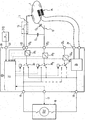
- a high-frequency.generator 10 is provided, which can be adjusted by way of the customary adjustment organs in a manner known per se.
- the HF generator 10 comprises an active output 15 and a neutral output 16, the latter being connected to an indifferent electrode 14 by way of a test-circuitry component 25 and a connector 24.
- the indifferent electrode 14 is attached to the patient 1 in such a way as to ensure that only a slight density of current will be transferred from the indifferent electrode 14 into the tissue 1. The safety of the contact is tested by the test circuitry 25.
- the signal from the active output 15 is sent to one pole of each of the change-over switches 30 1 to 30 n .
- the second pole of each switch 30, to 30 n is connected to the neutral output 16.
- the third pole (input) of the change-over switches 30 1 to 30 n is connected to working connectors 22 1 to 22 n of the safety device 20 by way of transformers 33 1 to 33 n .
- the transformers 33 1 to 33 n ascertain which currents are flowing through the working connectors 22 1 to 22 n , or which voltages are present at them.
- an active instrument 11 i.e. one that is being used at present, is attached to a first working connector 22 1 .
- the user actuates a switch 13 on the active instrument 11 or a pedal switch (13), each of which is connected by way of a control connector 23 or 23', respectively, to a control means 21 that is preferably designed as a microprocessor.
- the control means 21 receives the signals from the switch 13 and the transformers 33 1 to 33 n .
- control means 21 is connected to the HF generator 10 in such a way that on one hand the HF generator 10 is controlled by the control means 21, while on the other hand the control means 21 is informed about operational states of the HF generator 10. Furthermore, the control means 21 is in controlling communication with the change-over switches 30, to 30 n , which in the present case are constructed as relays, so that in response to relevant signals from the control means 21 the working connectors 22 1 to 22 n can be switched by the change-over switches 30 1 to 30 n either to the active output 15 or to the neutral output 16.
- the control means 21 changes the state of the change-over switch 30 1 in such a way that the working connector 22, is applied to the active output 15 of the HF generator 10.
- the other change-over switches 30 2 to 30 n remain in the position shown in the drawing, so that the working connectors 22 2 to 22 n remain in communication with the neutral output 16.
- the control means 21 controls the HF generator 10 accordingly, so that the latter supplies a working current to-the active instrument 11 by way of the change-over switch 30 1 , the transformer 33 1 and the working connector 22 1 .
- the current circuit is closed by the tissue 1, the indifferent electrode 14 and the test circuitry 25, terminating at the neutral output 16 of the HF generator 10.
- the control means 21 If the fault current (measured by the transformer 33 2 ) exceeds a threshold that has been preset in the control means 21, the latter emits an alarm signal (shown here as a warning lamp). Alternatively or in addition (if a still higher threshold is exceeded) the control means 21 switches off the HF generator 10.
Landscapes
- Health & Medical Sciences (AREA)
- Surgery (AREA)
- Engineering & Computer Science (AREA)
- Life Sciences & Earth Sciences (AREA)
- Biomedical Technology (AREA)
- Otolaryngology (AREA)
- Nuclear Medicine, Radiotherapy & Molecular Imaging (AREA)
- Plasma & Fusion (AREA)
- Physics & Mathematics (AREA)
- Heart & Thoracic Surgery (AREA)
- Medical Informatics (AREA)
- Molecular Biology (AREA)
- Animal Behavior & Ethology (AREA)
- General Health & Medical Sciences (AREA)
- Public Health (AREA)
- Veterinary Medicine (AREA)
- Surgical Instruments (AREA)
Claims (2)
- HF-Chirurgieanordnung, welche aufweist:- mindestens einen HF-Generator (10) mit einem aktiven Ausgang (15) und einem neutralen Ausgang (16) zur Erzeugung eines Arbeitsstromes,- mindestens zwei Arbeits-Verbinder (221 bis 22n) zum Anschluss mindestens eines Instruments (11, 12), durch die der Arbeitsstrom an biologisches Gewebe (1) geleitet werden kann,- eine Sicherheitseinrichtung (20) zur Verringerung der durch Fehlerströme, die durch ein inaktives Instrument (12) fließen können, geschaffenen Gefahr, wobei die Sicherheitseinrichtung (20) eine Steuereinrichtung (21) aufweist, die derart gestaltet ist, dass in Reaktion auf ein Aktivierungssignal anfangs der Arbeits-Verbinder (221 bis 22n) eines Instruments (11, 12), welches zu aktivieren ist, mit dem aktiven Ausgang (15) des HF-Generators (10) verbunden wird und dann der HF-Generator (10) so gesteuert wird, dass er den Arbeitsstrom liefert,wobei
die Sicherheitseinrichtung (20) so gestaltet und mit den Arbeits-Verbindern (221 bis 22n) sowie dem neutralen Ausgang (16) verbunden ist, dass jeder Arbeits-Verbinder (221 bis 22n), außer dem Arbeits-Verbinder (221 bis 22n) des zu aktivierenden Instruments (11, 12), mit dem neutralen Ausgang (16) verbunden ist, wobei bei den Arbeits-Verbindern (221 bis 22n) Sampling-Elemente (331 bis 33n) zur Erfassung der Größe eines Stroms und/oder einer Spannung vorgesehen sind, wobei die Steuereinrichtung (21) so gestaltet ist, dass sie den HF-Generator (10) immer ausschaltet, wenn der Strom und/oder die Spannung an den Arbeits-Verbindern (221 bis 22n), die mit dem neutralen Ausgang verbunden sind, eine vorbestimmte Schwelle übersteigt. - HF-Chirurgieanordnung nach Anspruch 1,
dadurch gekennzeichnet, dass
Umschalter (301 bis 30n) zum Zwecke des Schaltens eines Arbeits-Verbinders (221 bis 22n) vom neutralen Ausgang (16) an den aktiven Ausgang (15) des HF-Generators (10) und zum Leiten eines Arbeitsstromes vom HF-Generator (10) an das Instrument (11) vorgesehen sind.
Applications Claiming Priority (2)
| Application Number | Priority Date | Filing Date | Title |
|---|---|---|---|
| DE102005040487.1A DE102005040487B4 (de) | 2005-08-26 | 2005-08-26 | HF-Chirurgiegerät |
| PCT/EP2006/007844 WO2007022864A1 (en) | 2005-08-26 | 2006-08-08 | Safety device for a hf-surgery appliance |
Publications (2)
| Publication Number | Publication Date |
|---|---|
| EP1937173A1 EP1937173A1 (de) | 2008-07-02 |
| EP1937173B1 true EP1937173B1 (de) | 2016-06-29 |
Family
ID=37056567
Family Applications (1)
| Application Number | Title | Priority Date | Filing Date |
|---|---|---|---|
| EP06776681.6A Ceased EP1937173B1 (de) | 2005-08-26 | 2006-08-08 | Sicherheitsvorrichtung für ein hf-operationsgerät |
Country Status (6)
| Country | Link |
|---|---|
| US (1) | US20080221563A1 (de) |
| EP (1) | EP1937173B1 (de) |
| JP (1) | JP4970453B2 (de) |
| CN (1) | CN101247767B (de) |
| DE (1) | DE102005040487B4 (de) |
| WO (1) | WO2007022864A1 (de) |
Families Citing this family (6)
| Publication number | Priority date | Publication date | Assignee | Title |
|---|---|---|---|---|
| US9833281B2 (en) | 2008-08-18 | 2017-12-05 | Encision Inc. | Enhanced control systems including flexible shielding and support systems for electrosurgical applications |
| US8500728B2 (en) * | 2008-08-18 | 2013-08-06 | Encision, Inc. | Enhanced control systems including flexible shielding and support systems for electrosurgical applications |
| CN102159150B (zh) | 2008-10-01 | 2014-07-23 | 爱尔伯电子医疗设备公司 | 电外科高频发生器 |
| US8600334B2 (en) * | 2011-07-13 | 2013-12-03 | Biosense Webster (Israel), Ltd. | Patient leakage current limitation |
| CN109374952B (zh) * | 2018-12-03 | 2024-02-02 | 四川中测仪器科技有限公司 | 一种高频电刀漏电流的全自动测量系统和测量方法 |
| US12137986B2 (en) | 2021-09-29 | 2024-11-12 | Cilag Gmbh International | Methods for controlling cooperative surgical instruments |
Family Cites Families (11)
| Publication number | Priority date | Publication date | Assignee | Title |
|---|---|---|---|---|
| US4171700A (en) * | 1976-10-13 | 1979-10-23 | Erbe Elektromedizin Gmbh & Co. Kg | High-frequency surgical apparatus |
| DE3523871C3 (de) * | 1985-07-04 | 1994-07-28 | Erbe Elektromedizin | Hochfrequenz-Chirurgiegerät |
| US5152762A (en) * | 1990-11-16 | 1992-10-06 | Birtcher Medical Systems, Inc. | Current leakage control for electrosurgical generator |
| US5688269A (en) * | 1991-07-10 | 1997-11-18 | Electroscope, Inc. | Electrosurgical apparatus for laparoscopic and like procedures |
| US5372596A (en) * | 1993-07-27 | 1994-12-13 | Valleylab Inc. | Apparatus for leakage control and method for its use |
| US5496312A (en) | 1993-10-07 | 1996-03-05 | Valleylab Inc. | Impedance and temperature generator control |
| US6039732A (en) * | 1995-04-18 | 2000-03-21 | Olympus Optical Co., Ltd. | Electric operation apparatus |
| US5830212A (en) * | 1996-10-21 | 1998-11-03 | Ndm, Inc. | Electrosurgical generator and electrode |
| US5936536A (en) * | 1997-04-08 | 1999-08-10 | Medicor Corporation | Electrical insulation testing device and method for electrosurgical instruments |
| CN1463769A (zh) * | 2002-06-05 | 2003-12-31 | 马尔达卡股份有限公司 | 热疗器 |
| DE10253819A1 (de) * | 2002-11-18 | 2004-07-01 | Storz Endoskop Produktions Gmbh | Elektrochirurgische Vorrichtung sowie Verfahren zum Betreiben derselben |
-
2005
- 2005-08-26 DE DE102005040487.1A patent/DE102005040487B4/de not_active Expired - Fee Related
-
2006
- 2006-08-08 CN CN2006800306858A patent/CN101247767B/zh not_active Expired - Fee Related
- 2006-08-08 US US12/064,802 patent/US20080221563A1/en not_active Abandoned
- 2006-08-08 JP JP2008527338A patent/JP4970453B2/ja not_active Expired - Fee Related
- 2006-08-08 WO PCT/EP2006/007844 patent/WO2007022864A1/en not_active Ceased
- 2006-08-08 EP EP06776681.6A patent/EP1937173B1/de not_active Ceased
Non-Patent Citations (1)
| Title |
|---|
| None * |
Also Published As
| Publication number | Publication date |
|---|---|
| DE102005040487A1 (de) | 2007-04-05 |
| CN101247767A (zh) | 2008-08-20 |
| US20080221563A1 (en) | 2008-09-11 |
| DE102005040487B4 (de) | 2014-02-06 |
| JP4970453B2 (ja) | 2012-07-04 |
| JP2009505702A (ja) | 2009-02-12 |
| CN101247767B (zh) | 2010-09-01 |
| WO2007022864A1 (en) | 2007-03-01 |
| EP1937173A1 (de) | 2008-07-02 |
Similar Documents
| Publication | Publication Date | Title |
|---|---|---|
| EP2792326B1 (de) | Elektrochirurgische Vorrichtung mit mehreren Tasten | |
| EP1905373B1 (de) | Wandler für Hochfrequenzspannungsmessung | |
| ES3055909T3 (en) | Electrosurgical system | |
| US20210045804A1 (en) | Token-based electrosurgical instrument activation | |
| US8251989B1 (en) | Combined bipolar and monopolar electrosurgical instrument and method | |
| US7422589B2 (en) | System and method for performing an electrosurgical procedure | |
| US9687291B2 (en) | Treatment system | |
| EP2160993B1 (de) | Elektrochirurgische Vorrichtung mit Hochgeschwindigkeits-Energiewiederherstellung | |
| US20140249523A1 (en) | System and method for monitoring electrosurgical systems | |
| US9949782B2 (en) | Method for the control of a medical device as a function of neutral electrode impedance | |
| JPH0898845A (ja) | 組織を電気外科的に処置するための方法と器具 | |
| AU2009213017A1 (en) | Electrosurgical apparatus with high speed energy recovery | |
| AU2012201142A1 (en) | System and method for detecting and suppressing arc formation during an electrosurgical procedure | |
| JP2002078718A (ja) | 無線周波(アールエフ)漏洩を削減した電気外科用ジェネレータ | |
| EP1937173B1 (de) | Sicherheitsvorrichtung für ein hf-operationsgerät | |
| EP3641681A1 (de) | Chirurgische anordnung, system und elektrodenanordnung | |
| JP5662322B2 (ja) | 電気外科的hf生成器 | |
| JPH08280706A (ja) | 高周波焼灼装置 | |
| JPH10146344A (ja) | 電気手術装置 | |
| JPH08308851A (ja) | 電気手術装置 | |
| EP2540243B1 (de) | Elektrochirurgisches instrument | |
| JPH0134618B2 (de) | ||
| JPH0313897B2 (de) | ||
| JP2002000616A (ja) | 電気手術器およびそれに用いられる出力時間制御装置 |
Legal Events
| Date | Code | Title | Description |
|---|---|---|---|
| PUAI | Public reference made under article 153(3) epc to a published international application that has entered the european phase |
Free format text: ORIGINAL CODE: 0009012 |
|
| 17P | Request for examination filed |
Effective date: 20080314 |
|
| AK | Designated contracting states |
Kind code of ref document: A1 Designated state(s): DE FR GB IT |
|
| RBV | Designated contracting states (corrected) |
Designated state(s): DE FR GB IT |
|
| 17Q | First examination report despatched |
Effective date: 20100909 |
|
| DAX | Request for extension of the european patent (deleted) | ||
| GRAP | Despatch of communication of intention to grant a patent |
Free format text: ORIGINAL CODE: EPIDOSNIGR1 |
|
| INTG | Intention to grant announced |
Effective date: 20160210 |
|
| GRAR | Information related to intention to grant a patent recorded |
Free format text: ORIGINAL CODE: EPIDOSNIGR71 |
|
| GRAS | Grant fee paid |
Free format text: ORIGINAL CODE: EPIDOSNIGR3 |
|
| GRAA | (expected) grant |
Free format text: ORIGINAL CODE: 0009210 |
|
| AK | Designated contracting states |
Kind code of ref document: B1 Designated state(s): DE FR GB IT |
|
| INTG | Intention to grant announced |
Effective date: 20160520 |
|
| REG | Reference to a national code |
Ref country code: GB Ref legal event code: FG4D |
|
| REG | Reference to a national code |
Ref country code: DE Ref legal event code: R096 Ref document number: 602006049472 Country of ref document: DE |
|
| REG | Reference to a national code |
Ref country code: FR Ref legal event code: PLFP Year of fee payment: 11 |
|
| RAP2 | Party data changed (patent owner data changed or rights of a patent transferred) |
Owner name: ERBE ELEKTROMEDIZIN GMBH |
|
| REG | Reference to a national code |
Ref country code: DE Ref legal event code: R097 Ref document number: 602006049472 Country of ref document: DE |
|
| PLBE | No opposition filed within time limit |
Free format text: ORIGINAL CODE: 0009261 |
|
| STAA | Information on the status of an ep patent application or granted ep patent |
Free format text: STATUS: NO OPPOSITION FILED WITHIN TIME LIMIT |
|
| 26N | No opposition filed |
Effective date: 20170330 |
|
| REG | Reference to a national code |
Ref country code: FR Ref legal event code: PLFP Year of fee payment: 12 |
|
| PGFP | Annual fee paid to national office [announced via postgrant information from national office to epo] |
Ref country code: FR Payment date: 20170828 Year of fee payment: 12 Ref country code: IT Payment date: 20170822 Year of fee payment: 12 Ref country code: GB Payment date: 20170830 Year of fee payment: 12 |
|
| PGFP | Annual fee paid to national office [announced via postgrant information from national office to epo] |
Ref country code: DE Payment date: 20171030 Year of fee payment: 12 |
|
| REG | Reference to a national code |
Ref country code: DE Ref legal event code: R119 Ref document number: 602006049472 Country of ref document: DE |
|
| GBPC | Gb: european patent ceased through non-payment of renewal fee |
Effective date: 20180808 |
|
| PG25 | Lapsed in a contracting state [announced via postgrant information from national office to epo] |
Ref country code: DE Free format text: LAPSE BECAUSE OF NON-PAYMENT OF DUE FEES Effective date: 20190301 Ref country code: IT Free format text: LAPSE BECAUSE OF NON-PAYMENT OF DUE FEES Effective date: 20180808 |
|
| PG25 | Lapsed in a contracting state [announced via postgrant information from national office to epo] |
Ref country code: FR Free format text: LAPSE BECAUSE OF NON-PAYMENT OF DUE FEES Effective date: 20180831 |
|
| PG25 | Lapsed in a contracting state [announced via postgrant information from national office to epo] |
Ref country code: GB Free format text: LAPSE BECAUSE OF NON-PAYMENT OF DUE FEES Effective date: 20180808 |