EP1937155B1 - Dispositif de tension de ligaments - Google Patents
Dispositif de tension de ligaments Download PDFInfo
- Publication number
- EP1937155B1 EP1937155B1 EP06806368.4A EP06806368A EP1937155B1 EP 1937155 B1 EP1937155 B1 EP 1937155B1 EP 06806368 A EP06806368 A EP 06806368A EP 1937155 B1 EP1937155 B1 EP 1937155B1
- Authority
- EP
- European Patent Office
- Prior art keywords
- ligament
- tensioning device
- bearing plate
- proximal
- distal
- Prior art date
- Legal status (The legal status is an assumption and is not a legal conclusion. Google has not performed a legal analysis and makes no representation as to the accuracy of the status listed.)
- Active
Links
- 210000003041 ligament Anatomy 0.000 title claims description 11
- 238000006073 displacement reaction Methods 0.000 claims description 9
- 210000000629 knee joint Anatomy 0.000 claims description 7
- 210000000689 upper leg Anatomy 0.000 claims description 6
- 229910000831 Steel Inorganic materials 0.000 claims description 5
- 230000006835 compression Effects 0.000 claims description 5
- 238000007906 compression Methods 0.000 claims description 5
- 239000010959 steel Substances 0.000 claims description 5
- 230000008878 coupling Effects 0.000 claims description 4
- 238000010168 coupling process Methods 0.000 claims description 4
- 238000005859 coupling reaction Methods 0.000 claims description 4
- 210000002303 tibia Anatomy 0.000 claims description 4
- RTAQQCXQSZGOHL-UHFFFAOYSA-N Titanium Chemical compound [Ti] RTAQQCXQSZGOHL-UHFFFAOYSA-N 0.000 claims description 3
- 230000005540 biological transmission Effects 0.000 claims description 3
- 239000002775 capsule Substances 0.000 claims description 3
- 239000007943 implant Substances 0.000 claims description 3
- 239000010936 titanium Substances 0.000 claims description 3
- 229910052719 titanium Inorganic materials 0.000 claims description 3
- 238000002513 implantation Methods 0.000 claims description 2
- 238000003780 insertion Methods 0.000 claims description 2
- 230000037431 insertion Effects 0.000 claims description 2
- 210000000281 joint capsule Anatomy 0.000 claims description 2
- 239000000463 material Substances 0.000 claims description 2
- 238000004804 winding Methods 0.000 claims description 2
- 210000003414 extremity Anatomy 0.000 claims 6
- 230000004913 activation Effects 0.000 claims 1
- 238000010276 construction Methods 0.000 claims 1
- 229910052751 metal Inorganic materials 0.000 claims 1
- 239000002184 metal Substances 0.000 claims 1
- 210000002414 leg Anatomy 0.000 description 13
- 230000006978 adaptation Effects 0.000 description 4
- 210000000988 bone and bone Anatomy 0.000 description 4
- 210000003127 knee Anatomy 0.000 description 4
- 238000013461 design Methods 0.000 description 3
- 230000004048 modification Effects 0.000 description 3
- 238000012986 modification Methods 0.000 description 3
- 230000009471 action Effects 0.000 description 2
- 230000008901 benefit Effects 0.000 description 2
- 230000001419 dependent effect Effects 0.000 description 2
- 238000001356 surgical procedure Methods 0.000 description 2
- 238000011161 development Methods 0.000 description 1
- 230000018109 developmental process Effects 0.000 description 1
- 230000007246 mechanism Effects 0.000 description 1
- 238000000034 method Methods 0.000 description 1
- 125000006850 spacer group Chemical group 0.000 description 1
Images


Classifications
-
- A—HUMAN NECESSITIES
- A61—MEDICAL OR VETERINARY SCIENCE; HYGIENE
- A61F—FILTERS IMPLANTABLE INTO BLOOD VESSELS; PROSTHESES; DEVICES PROVIDING PATENCY TO, OR PREVENTING COLLAPSING OF, TUBULAR STRUCTURES OF THE BODY, e.g. STENTS; ORTHOPAEDIC, NURSING OR CONTRACEPTIVE DEVICES; FOMENTATION; TREATMENT OR PROTECTION OF EYES OR EARS; BANDAGES, DRESSINGS OR ABSORBENT PADS; FIRST-AID KITS
- A61F2/00—Filters implantable into blood vessels; Prostheses, i.e. artificial substitutes or replacements for parts of the body; Appliances for connecting them with the body; Devices providing patency to, or preventing collapsing of, tubular structures of the body, e.g. stents
- A61F2/02—Prostheses implantable into the body
- A61F2/08—Muscles; Tendons; Ligaments
- A61F2/0811—Fixation devices for tendons or ligaments
-
- A—HUMAN NECESSITIES
- A61—MEDICAL OR VETERINARY SCIENCE; HYGIENE
- A61B—DIAGNOSIS; SURGERY; IDENTIFICATION
- A61B17/00—Surgical instruments, devices or methods, e.g. tourniquets
- A61B17/02—Surgical instruments, devices or methods, e.g. tourniquets for holding wounds open; Tractors
- A61B17/025—Joint distractors
-
- A—HUMAN NECESSITIES
- A61—MEDICAL OR VETERINARY SCIENCE; HYGIENE
- A61F—FILTERS IMPLANTABLE INTO BLOOD VESSELS; PROSTHESES; DEVICES PROVIDING PATENCY TO, OR PREVENTING COLLAPSING OF, TUBULAR STRUCTURES OF THE BODY, e.g. STENTS; ORTHOPAEDIC, NURSING OR CONTRACEPTIVE DEVICES; FOMENTATION; TREATMENT OR PROTECTION OF EYES OR EARS; BANDAGES, DRESSINGS OR ABSORBENT PADS; FIRST-AID KITS
- A61F2/00—Filters implantable into blood vessels; Prostheses, i.e. artificial substitutes or replacements for parts of the body; Appliances for connecting them with the body; Devices providing patency to, or preventing collapsing of, tubular structures of the body, e.g. stents
- A61F2/02—Prostheses implantable into the body
- A61F2/08—Muscles; Tendons; Ligaments
- A61F2/0805—Implements for inserting tendons or ligaments
-
- A—HUMAN NECESSITIES
- A61—MEDICAL OR VETERINARY SCIENCE; HYGIENE
- A61F—FILTERS IMPLANTABLE INTO BLOOD VESSELS; PROSTHESES; DEVICES PROVIDING PATENCY TO, OR PREVENTING COLLAPSING OF, TUBULAR STRUCTURES OF THE BODY, e.g. STENTS; ORTHOPAEDIC, NURSING OR CONTRACEPTIVE DEVICES; FOMENTATION; TREATMENT OR PROTECTION OF EYES OR EARS; BANDAGES, DRESSINGS OR ABSORBENT PADS; FIRST-AID KITS
- A61F2/00—Filters implantable into blood vessels; Prostheses, i.e. artificial substitutes or replacements for parts of the body; Appliances for connecting them with the body; Devices providing patency to, or preventing collapsing of, tubular structures of the body, e.g. stents
- A61F2/02—Prostheses implantable into the body
- A61F2/30—Joints
- A61F2/46—Special tools or methods for implanting or extracting artificial joints, accessories, bone grafts or substitutes, or particular adaptations therefor
- A61F2/4657—Measuring instruments used for implanting artificial joints
-
- A—HUMAN NECESSITIES
- A61—MEDICAL OR VETERINARY SCIENCE; HYGIENE
- A61B—DIAGNOSIS; SURGERY; IDENTIFICATION
- A61B17/00—Surgical instruments, devices or methods, e.g. tourniquets
- A61B17/02—Surgical instruments, devices or methods, e.g. tourniquets for holding wounds open; Tractors
- A61B17/025—Joint distractors
- A61B2017/0268—Joint distractors for the knee
-
- A—HUMAN NECESSITIES
- A61—MEDICAL OR VETERINARY SCIENCE; HYGIENE
- A61F—FILTERS IMPLANTABLE INTO BLOOD VESSELS; PROSTHESES; DEVICES PROVIDING PATENCY TO, OR PREVENTING COLLAPSING OF, TUBULAR STRUCTURES OF THE BODY, e.g. STENTS; ORTHOPAEDIC, NURSING OR CONTRACEPTIVE DEVICES; FOMENTATION; TREATMENT OR PROTECTION OF EYES OR EARS; BANDAGES, DRESSINGS OR ABSORBENT PADS; FIRST-AID KITS
- A61F2/00—Filters implantable into blood vessels; Prostheses, i.e. artificial substitutes or replacements for parts of the body; Appliances for connecting them with the body; Devices providing patency to, or preventing collapsing of, tubular structures of the body, e.g. stents
- A61F2/02—Prostheses implantable into the body
- A61F2/30—Joints
- A61F2/38—Joints for elbows or knees
-
- A—HUMAN NECESSITIES
- A61—MEDICAL OR VETERINARY SCIENCE; HYGIENE
- A61F—FILTERS IMPLANTABLE INTO BLOOD VESSELS; PROSTHESES; DEVICES PROVIDING PATENCY TO, OR PREVENTING COLLAPSING OF, TUBULAR STRUCTURES OF THE BODY, e.g. STENTS; ORTHOPAEDIC, NURSING OR CONTRACEPTIVE DEVICES; FOMENTATION; TREATMENT OR PROTECTION OF EYES OR EARS; BANDAGES, DRESSINGS OR ABSORBENT PADS; FIRST-AID KITS
- A61F2/00—Filters implantable into blood vessels; Prostheses, i.e. artificial substitutes or replacements for parts of the body; Appliances for connecting them with the body; Devices providing patency to, or preventing collapsing of, tubular structures of the body, e.g. stents
- A61F2/02—Prostheses implantable into the body
- A61F2/30—Joints
- A61F2/46—Special tools or methods for implanting or extracting artificial joints, accessories, bone grafts or substitutes, or particular adaptations therefor
- A61F2/4603—Special tools or methods for implanting or extracting artificial joints, accessories, bone grafts or substitutes, or particular adaptations therefor for insertion or extraction of endoprosthetic joints or of accessories thereof
-
- A—HUMAN NECESSITIES
- A61—MEDICAL OR VETERINARY SCIENCE; HYGIENE
- A61F—FILTERS IMPLANTABLE INTO BLOOD VESSELS; PROSTHESES; DEVICES PROVIDING PATENCY TO, OR PREVENTING COLLAPSING OF, TUBULAR STRUCTURES OF THE BODY, e.g. STENTS; ORTHOPAEDIC, NURSING OR CONTRACEPTIVE DEVICES; FOMENTATION; TREATMENT OR PROTECTION OF EYES OR EARS; BANDAGES, DRESSINGS OR ABSORBENT PADS; FIRST-AID KITS
- A61F2/00—Filters implantable into blood vessels; Prostheses, i.e. artificial substitutes or replacements for parts of the body; Appliances for connecting them with the body; Devices providing patency to, or preventing collapsing of, tubular structures of the body, e.g. stents
- A61F2/02—Prostheses implantable into the body
- A61F2/30—Joints
- A61F2/46—Special tools or methods for implanting or extracting artificial joints, accessories, bone grafts or substitutes, or particular adaptations therefor
- A61F2/4684—Trial or dummy prostheses
-
- A—HUMAN NECESSITIES
- A61—MEDICAL OR VETERINARY SCIENCE; HYGIENE
- A61F—FILTERS IMPLANTABLE INTO BLOOD VESSELS; PROSTHESES; DEVICES PROVIDING PATENCY TO, OR PREVENTING COLLAPSING OF, TUBULAR STRUCTURES OF THE BODY, e.g. STENTS; ORTHOPAEDIC, NURSING OR CONTRACEPTIVE DEVICES; FOMENTATION; TREATMENT OR PROTECTION OF EYES OR EARS; BANDAGES, DRESSINGS OR ABSORBENT PADS; FIRST-AID KITS
- A61F2/00—Filters implantable into blood vessels; Prostheses, i.e. artificial substitutes or replacements for parts of the body; Appliances for connecting them with the body; Devices providing patency to, or preventing collapsing of, tubular structures of the body, e.g. stents
- A61F2/02—Prostheses implantable into the body
- A61F2/30—Joints
- A61F2/46—Special tools or methods for implanting or extracting artificial joints, accessories, bone grafts or substitutes, or particular adaptations therefor
- A61F2/4657—Measuring instruments used for implanting artificial joints
- A61F2002/4658—Measuring instruments used for implanting artificial joints for measuring dimensions, e.g. length
- A61F2002/4661—Measuring instruments used for implanting artificial joints for measuring dimensions, e.g. length for measuring thickness
Definitions
- the invention relates to a ligament-tensioning device for use in the implantation of joint or skeletal implants according to the preamble of claim 1.
- Ligament-tensioning devices with this function are known. So is about from the WO 00/78225 A1 a ligament-tensioning device known in addition to a prismatic, cylindrical or plate-shaped base body having a contact surface for engagement with a first, adjacent to a non-spherical joint bone and a right and left clamping lever with second bearing surfaces, which on the joint-side surface of a second To bring the joint of adjacent bone are coordinated by operating associated handles and levers. The opposing parts (contact surfaces) are supported against each other by four-bar lever mechanism.
- Another ligament-tensioning device which comprises a first, distal abutment plate for abutment with a first skeletal part and a second, proximal abutment plate for abutment with a second skeletal part, wherein the two abutment plates are displaceable relative to one another by a hydraulic drive and in particular via a central axis tilted against each other. They are also connected to each other via a base body, wherein the distal abutment plate is in particular firmly connected thereto.
- US 2005/02041 A1 describes a dynamic spacer for measuring a flexion-extension distance during knee arthoplasty.
- US 2005/177170 A1 discloses an apparatus for a knee surgery, the apparatus comprising a tibial component, a fixed femoral component and an adjustable femoral component.
- US 6 056 756 A describes an instrument for prosthetic joint replacement surgery with a lifting device for supporting a bone and a jig to facilitate the preparation of the bone for securing a prosthetic end component.
- the known ligament-tensioning devices in use according to the present experience, still have certain disadvantages. These relate in particular to the desired exact alignment between the opposing support plates and associated with a hydraulic drive device effort. In addition, the respective joint must be kept open when using the known ligament tensioning devices, since essential parts of the device protrude.
- the invention is therefore based on the object to provide an inexpensive and the requirements of practice in a reliable manner sufficient, improved ligament-tensioning device with versatile applications.
- the invention includes the essential idea to provide in the respective joint fully insertable ligament-tensioning device, which makes it possible to close the joint capsule after insertion again.
- the bearing plates in adaptation to the respective joint - such as a knee joint - to dimension, and protruding parts (such as in the prior art protruding handles or levers or hydraulic lines) are to be avoided as far as possible.
- the invention includes the idea of providing a purely internal drive or internal displacement means for the relative displacement of the opposing contact plates.
- the invention includes the idea of providing a precise parallel guidance between the distal abutment plate and the proximal abutment plates in anterior-dorsal as well as medial-lateral direction. This is realized by a suitable guidance according to the scissors principle.
- other two-level parallel guides eg using two non-axis parallel to each other (in particular an angle of 90 ° to each other enclosing) hinge joints.
- the invention includes, in a relatively independent form, the idea of providing a separate drive element for driving off each other between the distal abutment plate and the proximal abutment plates, namely a drive element without auxiliary energy.
- the invention finally includes the idea of associating with each proximal abutment plate a spring element which, in an initial state in which the proximal abutment plate is at a minimum distance from the distal abutment plate, stores the drive energy and, when the ligament adjuster is put into operation, increases the distance releases.
- this spring element or the opposite bearing plates a lock for releasable fixation in the starting position.
- auxiliary power such as an electric motor, electromagnetic, hydraulic or pneumatic drive
- This can drive both proximal abutment plates together, with their end position can be set in the balance of power with the surrounding capsule / ligament structure differently.
- the said drive means may also be provided separately for each proximal contact plate.
- proximal abutment plate are used with reference to preferred operating positions of the ligament-tensioner, such as when used in the knee.
- tibial attachment plate or femur attachment plate one could synonymously also speak of a tibial attachment plate or femur attachment plate;
- the spring element has a compression spring element which is arranged in a covering region of the proximal and distal abutment plates and is supported against both.
- the spring element on a steel or titanium coil spring with a suitable spring characteristic. It is characterized by a spring stiffness, which is tuned to a predetermined clamping force, in particular to provide over its stroke substantially constant clamping force in the range between 50 and 90 N, in particular of 70 N, to provide.
- the use of tailored special designs of the compression spring is preferred.
- a preferred form from the current point of view is characterized in that the steel or titanium coil spring is designed to increase the stroke conical or double-conical and in particular has a slope proportional to the local coil diameter diagonal.
- the conical shape of the spring element is chosen so that the overall height in the tensioned state is substantially reduced compared to a comparable coil spring with a cylindrical basic shape.
- the spring element on a spiral spring element namely, for example, a steel spiral or leaf spring.
- the present as a parallel guide scissors guide preferably has two near opposite ends of the proximal contact plate arranged, so as far as possible from each other spaced scissor hinges. In various embodiments of the invention, these can be arranged in a ventral-dorsal direction (behind one another) or in a medial-lateral direction (next to one another).
- An advantageous embodiment of the scissor guide is characterized in that the ends of the scissors joints are inserted into grooves of the distal or proximal contact plate and one leg or one end of both legs is rotatably fixed therein by perpendicular to the groove extension direction extending bearing pins.
- a sliding pin for guiding the respective leg or end is provided in a prepared in adaptation to the sliding pin groove at both ends of the free leg or at the respective free end of both legs.
- the scissor hinges are connected to one another via at least one connecting rod attached at the end of each leg.
- first and second proximal abutment plate each comprise an upper and lower part, wherein in the lower part means for holding the spring element and the scissor guide are provided and the upper part to increase the thickness of the respective Attachment plate is releasably fixed on the lower part.
- the ligament-tensioning device This can be used with a set of different thick tops for particularly precise solution of the mentioned adaptation task.
- the above-mentioned locking is conveniently accomplished by providing releasable locking means on the distal abutment plate or the first and second proximal abutment plates for independently locking the first and second proximal abutment plates to the distal abutment plate at a minimum distance and maximum spring tension therebetween are.
- the locking means each have a pivotally mounted on the respective bearing plate and engaging in the opposite bearing plate hook on which a first tool engagement portion is provided for actuation.
- the tool engagement portion is preferably designed to engage an Allen tool, such as a 3.5 mm Allen key.
- a first embodiment of the locking means with pivotable hook is provided that from the material of the first and second proximal abutment plate in spatial association with the hinged to the distal abutment plate hook an engagement portion is prepared for this.
- a second embodiment provides that in each case a first bearing pin of a scissors joint of the first and second proximal abutment plate protrudes beyond its outer edge and is arranged relative to the pivotable on the distal abutment plate hooks so that it forms the abutment of the locking means.
- a first bearing pin of a scissors joint of the first and second proximal abutment plate protrudes beyond its outer edge and is arranged relative to the pivotable on the distal abutment plate hooks so that it forms the abutment of the locking means.
- a second tool engagement section in particular a cylindrical recess, for engaging a positioning tool is preferably provided on the side edges of the distal abutment plate and the first and second proximal abutment plates intended.
- the provision of a separate tool is in view of the realization of a completely joint integrated ligament tensioner of particular advantage.
- a further expedient embodiment provides for a design for releasably coupling a sizer, which flexes the proximal and distal skeleton parts in such a way that an axis transmission from one skeleton part to the other is possible taking into account the ligament tension.
- the coupling also includes a simple application to suitably provided contact surfaces, but preferably connecting means for fixing the sizer to the distal abutment plate.
- the connecting means comprise two clamp-like extensions on the distal abutment plate, which each have a side edge of the proximal abutment plates guided around a base plate of the sizer.
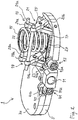
- Fig. 1 - 4th show in different views and different states a ligament-tensioning device 1, wherein Fig. 1 this interacts with a positioning tool.
- the ligament-tensioning device 1 comprises an approximately kidney-shaped distal abutment plate 5 in plan view and two of these proximal abutment plates 7 and 9, which are parallel and approximately half overlapping each, each comprising a lower part 7a, 9a and an upper part 7b, 9b.
- cylindrical recesses 11 are provided as engagement sections on the frontal side edges of the distal and proximal abutment plates. (In Fig. 1 thereof are the recesses in the proximal contact plates, more precisely: the upper parts 7b, 9b, shown during Fig. 2 the central recess 11 in the distal abutment plate 5 shows.)
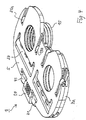
- proximal bearing plates 7 and 9 are each connected to one another via a scissors guide 13 and biased against each other by a steel compression spring 15 as a spring element.
- the coil spring 15 is seated in an adapted circular recess 17 on the upper side of the distal abutment plate 5; a similar (not shown) storage is provided on the underside of each associated proximal abutment plate.
- the scissors guide 13 comprises a medial and lateral scissors articulation 19 and 21, each of which comprises two legs 19a, 19b and 21a, 21b which are rotatably connected via a rotation axis 23 or 25.
- the legs 19a, 21a are integrally formed via a bridge or connecting rod 27 connected at one end to each other, while in their other end in each case a sliding pin or pin 29a and 31a for connection to the (in Fig. 2 and 3 omitted) lower part 9a of the second abutment plate is inserted.
- one end of the legs 19b, 21b is connected via a connecting rod 33 inserted perpendicular to the extension plane, which projects beyond the medial or lateral outer side of the respective leg and forms further (not separately designated) sliding pins there.
- a separate sliding pin 29b and 31b is provided at the opposite ends of the legs 19b, 21b.
- These slide pins 29b, 31b engage (as best in FIG Fig. 3 can be seen) in correspondingly dimensioned, in the position of use of the ligament-tensioning device dorsal-ventral grooves 35, 37 of the distal abutment plate 5 and fix the scissors hereby slidably in the distal abutment plate 5.
- As in the lower part 7a of the first proximal abutment plate 7 representing Section of Fig. 3 can be seen beginning to see - see detail "A" -, in the proximal contact plates a corresponding, not separately numbered groove structure is provided.
- Fig. 2 how best in Fig. 2 to recognize, on the ventral side edge (leading edge) of the distal abutment plate 5 on both sides of a cylindrical recess 11 containing extension two pivoting hook elements 41, 43 are mounted, each having an Allen-engaging portion 41a and 43a and a molded hook portion 41b and 43b.
- the hook sections engage as in Fig. 2 can be seen in the region of the first proximal contact plate, in a corresponding to the hook shape shaped recess on the upper side of the respective bearing plate lower part a - wherein in Fig. 2 only the recess 45 is shown in the lower part 7a of the first proximal contact plate.
- the proximal abutment plates are kept at a minimum distance from the distal abutment plate.
- this lock is released, and the respective proximal contact plate can move away from the distal abutment plate under the bias of the associated compression spring 15 until its movement in force equilibrium with the on-site capsule. / Ligament tension comes to a standstill.
- a cylindrical coil spring 15 is shown, shows Fig. 5 as a modification, a double-conical coil spring 15 ', due to their lower in the tensioned state height at the ligament-tensioning device 1 after Fig. 1 - 4th can preferably be used.
- the slope of the winding in the lower and upper regions of larger diameter be lower than in the middle range, so that a perfect spring action over the entire stroke is guaranteed.
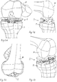
- the above-described ligament-tensioning device 1 is designed for use in a knee joint, and in Figs. 6A-6D This state of use is shown in different views. Good to see the adaptation of the dimensions, in particular the length / width ratio and the execution of the two proximal bearing plates 7, 9 on the anatomical conditions of the knee joint and especially the overall dimensions and size relations of the tibia T and the (resected) femur F.
- a ligament-tensioning device 1 'with a coupled sizer 47 is shown.
- An sizer is known to be used for intraoperative coupling of the tibia and femur in flexion such that axis transmission of the tibial axis can be made taking into account the ligament tension on the femur. It can also be used to define the optimal size and position of a knee implant in anterior-posterior direction and in rotation. The technical features of the sizer are not the subject of the present invention and are therefore not described here.
- connecting means between the ligament-tensioning device 1 'and the sizer 47 namely two clamp-like extensions or connecting straps 49a, 49b on the distal abutment plate 5, which overlap the proximal abutment plates (not designated here) on a lateral edge of the same and connect to a base 51 of the sizer 47.
- the embodiment of the invention is not limited to the embodiment described here and the last-mentioned modification of the spring element, but is also possible in a variety of modifications that are within the scope of professional action.
- a scissors guide which is arranged rotated relative to the embodiment shown by 90 ° and in the rest of a part of the sliding pins or spigots can also be formed as a bearing pin for stationary fixation of a respective leg end in the associated contact plate ,
- the upper parts may also be omitted, and numerous degrees of freedom exist with regard to the exact shape and dimensional relationships of the abutment plates.
Claims (29)
- Dispositif tenseur de ligaments (1), destiné à activer le système ligamentaire et/ou capsulaire lors de l'implantation d'un implant articulaire, pourvu d'une plaque d'appui distale (5) destinée à être appuyée sur une partie distale du squelette et d'une première et deuxième plaques d'appui proximales (7, 9), recouvrant chaque fois partiellement la plaque d'appui distale (5) dans une première position d'utilisation, destinées à être appuyées sur une partie proximale du squelette et de moyens destinés au déplacement relatif des plaques d'appui proximales (7, 9), pour agrandir leur écart par rapport à la plaque d'appui distale,
l'ensemble des composants majeurs du dispositif tenseur de ligaments, notamment la plaque d'appui distale (5) et la première et deuxième plaques d'appui proximales (7, 9) étant dimensionnées pour être logées entre des tronçons proches de l'articulation de la partie distale et proximale du squelette, de telle sorte qu'après l'insertion du dispositif tenseur de ligaments, une capsule articulaire puisse à nouveau être fermée,
caractérisé en ce que
les moyens de déplacement comportent un guidage par cisaillement (13) supportant la plaque d'appui proximale concernée en position parallèle par rapport à la plaque d'appui distale, laquelle entre la plaque d'appui distale et la plaque d'appui proximale concernée est conçue de manière rigide en torsion, de sorte à mettre à disposition un guidage parallèle précis, dans la direction ventrale-dorsale, ainsi que médiale-latérale, entre la plaque d'appui distale et la plaque d'appui proximale. - Dispositif tenseur de ligaments (1) selon la revendication 1,
caractérisé par
des moyens exclusivement internes pour le déplacement relatif des plaques d'appui proximales par rapport à la plaque d'appui distale. - Dispositif tenseur de ligaments (1) selon l'une quelconque des revendications précédentes,
caractérisé en ce que
les moyens de déplacement comportent au moins un élément à ressort (15), destiné à entraîner les plaques d'appui proximales, lequel dans une position initiale, dans laquelle les plaques d'appui proximales (7, 9) présentent un écart minimal par rapport à la plaque d'appui distale (5) garde accumulée l'énergie d'entraînement et la libère lors de la mise en fonction du tendeur de ligaments, pour agrandir l'écart. - Dispositif tenseur de ligaments (1) selon la revendication 3,
caractérisé en ce que
les moyens de déplacement comportent, en association à la première et deuxième plaques d'appui proximales chaque fois un élément à ressort (15), destiné à entraîner les plaques d'appui proximales. - Dispositif tenseur de ligaments (1) selon la revendication 3 ou 4,
caractérisé en ce que
le ou chaque élément à ressort (15) est conçu de sorte à être verrouillable. - Dispositif tenseur de ligaments (1) selon l'une quelconque des revendications 3 à 5,
caractérisé en ce que
l'élément à ressort (15) comporte un élément à ressort de pression qui est placé dans une zone de recouvrement des plaques d'appui proximales et distale. - Dispositif tenseur de ligaments (1) selon la revendication 6,
caractérisé en ce que
l'élément à ressort (15) comporte une vis hélicoïdale en acier ou en titane, qui pour agrandir la course est réalisée sous forme de cône ou de double cône et comporte notamment une inclinaison indirectement proportionnelle au diamètre local des spires. - Dispositif tenseur de ligaments (1) selon la revendication 3 ou 4,
caractérisé en ce que
l'élément à ressort (15) comporte un élément à ressort de flexion. - Dispositif tenseur de ligaments (1) selon la revendication 8,
caractérisé en ce que
l'élément à ressort (15) comporte un ressort métallique en spirale ou un ressort à lames. - Dispositif tenseur de ligaments (1) selon l'une quelconque des revendications précédentes,
caractérisé en ce que
le guidage par cisaillement (13) comporte deux articulations à cisaillement placées à proximité d'extrémités en vis-à-vis de la plaque d'appui proximale. - Dispositif tenseur de ligaments (1) selon la revendication 10,
caractérisé en ce que
les extrémités des articulations à cisaillement sont insérées dans des rainures de la plaque d'appui distale ou proximale et chaque fois une branche ou chaque fois une extrémité des deux branches y est fixée en rotation par tourillons et tenons coulissants s'écoulant dans la direction d'extension de la rainure. - Dispositif tenseur de ligaments (1) selon la revendication 11,
caractérisé en ce que
sur les deux extrémités de la branche libre ou sur les extrémités respectivement libres des deux branches est prévu un tenon glissant, destiné à guider la branche ou l'extrémité en question dans une rainure de la plaque d'appui distale ou proximale, façonnée en adaptation au tenon glissant. - Dispositif tenseur de ligaments (1) selon l'une quelconque des revendications 10 à 12,
caractérisé en ce que
les articulations en cisaillement sont assemblées par l'intermédiaire d'une tige d'assemblage, montée sur l'extrémité de chaque fois une branche. - Dispositif tenseur de ligaments (1) selon l'une quelconque des revendications précédentes,
caractérisé en ce que
la première et la deuxième plaques d'appui proximales (7, 9) comprennent chacune une partie supérieure et inférieure (7a, 7b, 9a, 9b), dans la partie inférieure (7a, 9a) étant prévus des moyens de maintien du guidage par cisaillement (13) et en option, de l'élément à ressort (15) et en ce que pour l'agrandissement à volonté de l'épaisseur de la plaque d'appui en question, la partie supérieure (7b, 9b) est fixée de manière amovible sur la partie inférieure. - Dispositif tenseur de ligaments (1) selon l'une quelconque des revendications précédentes,
caractérisé en ce que
sur la plaque d'appui distale (5) ou la première et deuxième plaques d'appui proximales (7, 9) sont prévus des moyens de verrouillage amovibles, pour le verrouillage indépendant de la première et de la deuxième plaques d'appui proximales avec la plaque d'appui distale, avec un écart minimal et au vis-à-vis de celle-ci. - Dispositif tenseur de ligaments (1) selon la revendication 15,
caractérisé en ce que
les moyens de verrouillage comportent chacun un crochet logé en pivotement sur la plaque d'appui en question et s'engageant dans la plaque d'appui opposée, sur lequel est prévu un premier segment d'engagement d'outil pour l'actionnement. - Dispositif tenseur de ligaments (1) selon la revendication 16,
caractérisé en ce que
le premier segment d'engagement d'outil est façonné pour l'engagement d'une clé Allen standard. - Dispositif tenseur de ligaments (1) selon la revendication 16 ou 17,
caractérisé en ce
qu'à partir de la matière de la première et de la deuxième plaques d'appui proximales (7, 9), en association physique au crochet articulé sur la plaque d'appui distale (5) est façonné un segment d'engagement pour celui-ci. - Dispositif tenseur de ligaments (1) selon l'une quelconque des revendications 16 à 18,
caractérisé en ce que
chaque fois un premier tenon d'une articulation par cisaillement de la première et de la deuxième plaques d'appui proximales (7, 9) déborde par-dessus leur bord extérieur et est placé par rapport au crochet pivotant sur la plaque d'appui distale (5), de sorte à former la butée des moyens de verrouillage. - Dispositif tenseur de ligaments (1) selon l'une quelconque des revendications 16 à 19,
caractérisé en ce que
chaque fois un deuxième tenon d'une articulation par cisaillement de la première et de la deuxième plaques d'appui proximales (7, 9) déborde par-dessus leur bord extérieur et est placé par rapport au crochet pivotant sur la plaque d'appui distale (5), de sorte à former son axe de pivotement. - Dispositif tenseur de ligaments (1) selon l'une quelconque des revendications précédentes,
caractérisé en ce que
sur les arêtes latérales de la plaque d'appui distale (5) et de la première et de la deuxième plaques d'appui proximales (7, 9) est prévu chaque fois un tronçon d'engagement d'outil, notamment un évidement cylindrique, pour l'engagement d'un outil de positionnement. - Dispositif tenseur de ligaments (1) selon l'une quelconque des revendications 3 à 21,
caractérisé par
un élément à ressort (15) dont la rigidité de ressort est adaptée à une force de tension prédéfinie, lequel met à disposition notamment une force de tension sensiblement constante sur sa course, de l'ordre compris entre 50 et 90 N, notamment de 70 N. - Dispositif tenseur de ligaments (1) selon l'une quelconque des revendications précédentes,
caractérisé en ce que
le rapport longueur/largeur, donc la dimension dans la direction médiale-latérale, par rapport à celle dans la direction ventrale-dorsale est adaptée aux proportions d'un tronçon coupé, proche de l'articulation de la partie de squelette voisine. - Dispositif tenseur de ligaments (1) selon l'une quelconque des revendications précédentes,
caractérisé par
la réalisation en adaptation à une rotule, les parties de squelette voisines étant un fémur et un tibia. - Dispositif tenseur de ligaments (1) selon la revendication 23 et 24,
caractérisé en ce
qu'en correspondance à un tibia proximal coupé, le rapport longueur/largeur correspond à 3/2. - Dispositif tenseur de ligaments (1) selon l'une quelconque des revendications précédentes,
caractérisé par
une conception pour un accouplement amovible d'un calibreur, lequel accouple la partie proximale et distale du squelette en flexion, de telle sorte qu'une transmission d'axe de l'une des parties du squelette sur l'autre soit possible sous considération de la tension des ligaments. - Dispositif tenseur de ligaments (1) selon la revendication 26,
caractérisé par
des moyens d'assemblage, destinés à fixer le calibreur sur la plaque d'appui distale (5). - Dispositif tenseur de ligaments (1) selon la revendication 27,
caractérisé en ce que
les moyens d'assemblage comportent deux prolongements en forme de crampons sur la plaque d'appui distale, lesquels, en enserrant chacun une arête latérale des plaques d'appui proximales (7, 9) sont guidés vers la plaque d'embase du calibreur. - Agencement d'un dispositif tenseur de ligaments (1) selon l'une quelconque des revendications précédentes et d'un calibreur, qui sont réalisés et accouplés l'un à l'autre de manière amovible, notamment en adaptation à une rotule.
Applications Claiming Priority (2)
| Application Number | Priority Date | Filing Date | Title |
|---|---|---|---|
| DE102005049851A DE102005049851A1 (de) | 2005-10-18 | 2005-10-18 | Bänderspanngerät |
| PCT/EP2006/010052 WO2007045460A2 (fr) | 2005-10-18 | 2006-10-18 | Dispositif de tension de ligaments |
Publications (2)
| Publication Number | Publication Date |
|---|---|
| EP1937155A2 EP1937155A2 (fr) | 2008-07-02 |
| EP1937155B1 true EP1937155B1 (fr) | 2018-09-26 |
Family
ID=37681381
Family Applications (1)
| Application Number | Title | Priority Date | Filing Date |
|---|---|---|---|
| EP06806368.4A Active EP1937155B1 (fr) | 2005-10-18 | 2006-10-18 | Dispositif de tension de ligaments |
Country Status (4)
| Country | Link |
|---|---|
| US (2) | US9216097B2 (fr) |
| EP (1) | EP1937155B1 (fr) |
| DE (1) | DE102005049851A1 (fr) |
| WO (1) | WO2007045460A2 (fr) |
Families Citing this family (85)
| Publication number | Priority date | Publication date | Assignee | Title |
|---|---|---|---|---|
| US8298262B2 (en) | 2006-02-03 | 2012-10-30 | Biomet Sports Medicine, Llc | Method for tissue fixation |
| US9017381B2 (en) | 2007-04-10 | 2015-04-28 | Biomet Sports Medicine, Llc | Adjustable knotless loops |
| US8137382B2 (en) | 2004-11-05 | 2012-03-20 | Biomet Sports Medicine, Llc | Method and apparatus for coupling anatomical features |
| US8128658B2 (en) | 2004-11-05 | 2012-03-06 | Biomet Sports Medicine, Llc | Method and apparatus for coupling soft tissue to bone |
| US7909851B2 (en) | 2006-02-03 | 2011-03-22 | Biomet Sports Medicine, Llc | Soft tissue repair device and associated methods |
| US7749250B2 (en) | 2006-02-03 | 2010-07-06 | Biomet Sports Medicine, Llc | Soft tissue repair assembly and associated method |
| US9801708B2 (en) | 2004-11-05 | 2017-10-31 | Biomet Sports Medicine, Llc | Method and apparatus for coupling soft tissue to a bone |
| US8118836B2 (en) | 2004-11-05 | 2012-02-21 | Biomet Sports Medicine, Llc | Method and apparatus for coupling soft tissue to a bone |
| US8361113B2 (en) | 2006-02-03 | 2013-01-29 | Biomet Sports Medicine, Llc | Method and apparatus for coupling soft tissue to a bone |
| US8840645B2 (en) | 2004-11-05 | 2014-09-23 | Biomet Sports Medicine, Llc | Method and apparatus for coupling soft tissue to a bone |
| US8303604B2 (en) | 2004-11-05 | 2012-11-06 | Biomet Sports Medicine, Llc | Soft tissue repair device and method |
| US7905904B2 (en) | 2006-02-03 | 2011-03-15 | Biomet Sports Medicine, Llc | Soft tissue repair device and associated methods |
| US7658751B2 (en) | 2006-09-29 | 2010-02-09 | Biomet Sports Medicine, Llc | Method for implanting soft tissue |
| US8088130B2 (en) | 2006-02-03 | 2012-01-03 | Biomet Sports Medicine, Llc | Method and apparatus for coupling soft tissue to a bone |
| US8998949B2 (en) | 2004-11-09 | 2015-04-07 | Biomet Sports Medicine, Llc | Soft tissue conduit device |
| US9538998B2 (en) | 2006-02-03 | 2017-01-10 | Biomet Sports Medicine, Llc | Method and apparatus for fracture fixation |
| US8652171B2 (en) | 2006-02-03 | 2014-02-18 | Biomet Sports Medicine, Llc | Method and apparatus for soft tissue fixation |
| US8251998B2 (en) | 2006-08-16 | 2012-08-28 | Biomet Sports Medicine, Llc | Chondral defect repair |
| US9078644B2 (en) | 2006-09-29 | 2015-07-14 | Biomet Sports Medicine, Llc | Fracture fixation device |
| US8597327B2 (en) | 2006-02-03 | 2013-12-03 | Biomet Manufacturing, Llc | Method and apparatus for sternal closure |
| US8506597B2 (en) | 2011-10-25 | 2013-08-13 | Biomet Sports Medicine, Llc | Method and apparatus for interosseous membrane reconstruction |
| US9149267B2 (en) | 2006-02-03 | 2015-10-06 | Biomet Sports Medicine, Llc | Method and apparatus for coupling soft tissue to a bone |
| US8562645B2 (en) | 2006-09-29 | 2013-10-22 | Biomet Sports Medicine, Llc | Method and apparatus for forming a self-locking adjustable loop |
| US8652172B2 (en) | 2006-02-03 | 2014-02-18 | Biomet Sports Medicine, Llc | Flexible anchors for tissue fixation |
| US8936621B2 (en) | 2006-02-03 | 2015-01-20 | Biomet Sports Medicine, Llc | Method and apparatus for forming a self-locking adjustable loop |
| US11311287B2 (en) | 2006-02-03 | 2022-04-26 | Biomet Sports Medicine, Llc | Method for tissue fixation |
| US8968364B2 (en) | 2006-02-03 | 2015-03-03 | Biomet Sports Medicine, Llc | Method and apparatus for fixation of an ACL graft |
| US8574235B2 (en) | 2006-02-03 | 2013-11-05 | Biomet Sports Medicine, Llc | Method for trochanteric reattachment |
| US8801783B2 (en) | 2006-09-29 | 2014-08-12 | Biomet Sports Medicine, Llc | Prosthetic ligament system for knee joint |
| US8771352B2 (en) | 2011-05-17 | 2014-07-08 | Biomet Sports Medicine, Llc | Method and apparatus for tibial fixation of an ACL graft |
| US10517587B2 (en) | 2006-02-03 | 2019-12-31 | Biomet Sports Medicine, Llc | Method and apparatus for forming a self-locking adjustable loop |
| US8562647B2 (en) | 2006-09-29 | 2013-10-22 | Biomet Sports Medicine, Llc | Method and apparatus for securing soft tissue to bone |
| US11259792B2 (en) | 2006-02-03 | 2022-03-01 | Biomet Sports Medicine, Llc | Method and apparatus for coupling anatomical features |
| US8500818B2 (en) | 2006-09-29 | 2013-08-06 | Biomet Manufacturing, Llc | Knee prosthesis assembly with ligament link |
| US9918826B2 (en) | 2006-09-29 | 2018-03-20 | Biomet Sports Medicine, Llc | Scaffold for spring ligament repair |
| US11259794B2 (en) | 2006-09-29 | 2022-03-01 | Biomet Sports Medicine, Llc | Method for implanting soft tissue |
| US8672969B2 (en) | 2006-09-29 | 2014-03-18 | Biomet Sports Medicine, Llc | Fracture fixation device |
| GB0621341D0 (en) | 2006-10-26 | 2006-12-06 | Howmedica Osteonics Corp | Knee distractor |
| US9005307B2 (en) | 2006-11-07 | 2015-04-14 | Biomedflex, Llc | Prosthetic ball-and-socket joint |
| US8308812B2 (en) | 2006-11-07 | 2012-11-13 | Biomedflex, Llc | Prosthetic joint assembly and joint member therefor |
| US8029574B2 (en) * | 2006-11-07 | 2011-10-04 | Biomedflex Llc | Prosthetic knee joint |
| US20110166671A1 (en) | 2006-11-07 | 2011-07-07 | Kellar Franz W | Prosthetic joint |
| DE102007040695A1 (de) * | 2007-08-29 | 2009-04-23 | Aesculap Ag | Chirurgischer Kontraktor |
| EP2158879A1 (fr) * | 2008-09-01 | 2010-03-03 | MMK Consulting GmbH | Maquette pour arthroplastie totale du genou |
| US20100250284A1 (en) * | 2009-03-26 | 2010-09-30 | Martin Roche | System and method for an orthopedic dynamic data repository and registry for request |
| US20100305710A1 (en) | 2009-05-28 | 2010-12-02 | Biomet Manufacturing Corp. | Knee Prosthesis |
| US8277456B2 (en) * | 2009-07-17 | 2012-10-02 | Ulrich Gmbh & Co. Kg | Spinal-column distractor |
| BR112012025998A2 (pt) | 2010-04-13 | 2016-06-28 | Smith & Nephew Inc | sistemas e métodos para tensionar ligamentos e outros tecidos moles |
| GB201006173D0 (en) | 2010-04-14 | 2010-06-02 | Depuy Ireland | A distractor |
| GB2479899A (en) | 2010-04-28 | 2011-11-02 | Biomet Uk Ltd | Alignment tool for use in joint replacement |
| GB201115411D0 (en) | 2011-09-07 | 2011-10-19 | Depuy Ireland | Surgical instrument |
| US9357991B2 (en) | 2011-11-03 | 2016-06-07 | Biomet Sports Medicine, Llc | Method and apparatus for stitching tendons |
| US9370350B2 (en) | 2011-11-10 | 2016-06-21 | Biomet Sports Medicine, Llc | Apparatus for coupling soft tissue to a bone |
| US9381013B2 (en) | 2011-11-10 | 2016-07-05 | Biomet Sports Medicine, Llc | Method for coupling soft tissue to a bone |
| US9314241B2 (en) | 2011-11-10 | 2016-04-19 | Biomet Sports Medicine, Llc | Apparatus for coupling soft tissue to a bone |
| US9381011B2 (en) | 2012-03-29 | 2016-07-05 | Depuy (Ireland) | Orthopedic surgical instrument for knee surgery |
| US9005208B2 (en) | 2013-02-28 | 2015-04-14 | Howmedica Osteonics Corp. | Ligament balancing femoral trial |
| US9757119B2 (en) | 2013-03-08 | 2017-09-12 | Biomet Sports Medicine, Llc | Visual aid for identifying suture limbs arthroscopically |
| US9918827B2 (en) | 2013-03-14 | 2018-03-20 | Biomet Sports Medicine, Llc | Scaffold for spring ligament repair |
| US11793424B2 (en) | 2013-03-18 | 2023-10-24 | Orthosensor, Inc. | Kinetic assessment and alignment of the muscular-skeletal system and method therefor |
| US9566020B2 (en) * | 2013-03-18 | 2017-02-14 | Orthosensor Inc | System and method for assessing, measuring, and correcting an anterior-posterior bone cut |
| WO2014183799A1 (fr) * | 2013-05-17 | 2014-11-20 | Brainlab Ag | Endoprothèse ajustable |
| GB2552759B (en) * | 2013-05-23 | 2018-05-02 | Moholkar Kirti | Kit of parts for use in knee replacement surgery |
| US10136886B2 (en) | 2013-12-20 | 2018-11-27 | Biomet Sports Medicine, Llc | Knotless soft tissue devices and techniques |
| US9615822B2 (en) | 2014-05-30 | 2017-04-11 | Biomet Sports Medicine, Llc | Insertion tools and method for soft anchor |
| US9700291B2 (en) | 2014-06-03 | 2017-07-11 | Biomet Sports Medicine, Llc | Capsule retractor |
| US10039543B2 (en) | 2014-08-22 | 2018-08-07 | Biomet Sports Medicine, Llc | Non-sliding soft anchor |
| US9955980B2 (en) | 2015-02-24 | 2018-05-01 | Biomet Sports Medicine, Llc | Anatomic soft tissue repair |
| US9974534B2 (en) | 2015-03-31 | 2018-05-22 | Biomet Sports Medicine, Llc | Suture anchor with soft anchor of electrospun fibers |
| US20170065438A1 (en) * | 2015-09-08 | 2017-03-09 | Brian G. Burnikel | Adjustable tibial trial |
| CN105178626B (zh) | 2015-09-16 | 2017-12-08 | 中建钢构有限公司 | 轻型多功能支承装置的顶紧力计算方法 |
| US9655740B1 (en) * | 2016-04-28 | 2017-05-23 | Spine Wave, Inc. | Expandable sizer instrument for spacing vertebral bodies |
| WO2017185108A2 (fr) * | 2016-04-28 | 2017-11-02 | Medfit Beratungs-Und Beteiligunges.M.B.H | Système d'équilibrage dynamique de ligaments (dlb) |
| US10136952B2 (en) * | 2016-06-16 | 2018-11-27 | Zimmer, Inc. | Soft tissue balancing in articular surgery |
| US11229489B2 (en) | 2016-06-16 | 2022-01-25 | Zimmer, Inc. | Soft tissue balancing in articular surgery |
| US11185425B2 (en) | 2016-12-22 | 2021-11-30 | Orthosensor Inc. | Surgical tensor configured to distribute loading through at least two pivot points |
| WO2018119360A1 (fr) * | 2016-12-22 | 2018-06-28 | Orthosensor Inc. | Appareil chirurgical pour supporter l'installation d'un élément prothétique et procédé associé |
| US11266512B2 (en) | 2016-12-22 | 2022-03-08 | Orthosensor Inc. | Surgical apparatus to support installation of a prosthetic component and method therefore |
| US11291437B2 (en) | 2016-12-22 | 2022-04-05 | Orthosensor Inc. | Tilting surgical tensor to support at least one bone cut |
| US11284873B2 (en) | 2016-12-22 | 2022-03-29 | Orthosensor Inc. | Surgical tensor where each distraction mechanism is supported and aligned by at least two guide shafts |
| US11678894B2 (en) | 2017-12-15 | 2023-06-20 | Jonathan P. Cabot | Knee balancing instrument |
| US10722168B2 (en) * | 2018-01-26 | 2020-07-28 | medFit Beratungs-und Beteiligungsges.m.B.H. | Dynamic ligament balancing system with pin positioning block |
| CN108904032A (zh) * | 2018-08-27 | 2018-11-30 | 黄玮 | 一种双纽扣钢板单袢固定机构及固定系统 |
| WO2021257702A1 (fr) * | 2020-06-16 | 2021-12-23 | Exactech, Inc. | Dispositifs d'équilibrage de ligament mécanique |
| US11612421B1 (en) * | 2021-09-20 | 2023-03-28 | Little Engine, LLC | Tensioner-balancer for knee joint |
Family Cites Families (17)
| Publication number | Priority date | Publication date | Assignee | Title |
|---|---|---|---|---|
| SE400922B (sv) * | 1971-11-06 | 1978-04-17 | Fujikoshi Kk | Godshanteringsanordning |
| US4501266A (en) * | 1983-03-04 | 1985-02-26 | Biomet, Inc. | Knee distraction device |
| DE3809793A1 (de) * | 1988-03-23 | 1989-10-05 | Link Waldemar Gmbh Co | Chirurgischer instrumentensatz |
| US5540696A (en) * | 1995-01-06 | 1996-07-30 | Zimmer, Inc. | Instrumentation for use in orthopaedic surgery |
| US6056756A (en) * | 1998-08-11 | 2000-05-02 | Johnson & Johnson Professional, Inc. | Femoral tensing and sizing device |
| DE29906909U1 (de) * | 1999-03-02 | 1999-09-30 | Plus Endoprothetik Ag Rotkreuz | Femurschlitten |
| DE29910761U1 (de) * | 1999-06-19 | 2000-11-23 | Mathys Medizinaltechnik Ag Bet | Bänderspannvorrichtung für nicht-kugelige Gelenke |
| US6251067B1 (en) | 1999-06-23 | 2001-06-26 | Advanced Research & Technology Institute | Male erectile prosthesis |
| US20030069644A1 (en) * | 2001-10-05 | 2003-04-10 | Nebojsa Kovacevic | Dual-tray teletibial implant |
| US20040097951A1 (en) * | 2002-11-18 | 2004-05-20 | Steffensmeier Scott J. | Measurement instrument for use in orthopaedic surgery |
| FR2851728B1 (fr) | 2003-02-27 | 2006-02-17 | Univ Joseph Fourier | Distracteur du genou |
| DE20320501U1 (de) * | 2003-06-23 | 2004-11-11 | Strempel, Archibald von, Prof. Dr.Dr. | Vorrichtung zur intraoperativen Messung der Seitenbänderspannung des Kniegelenks |
| US7455647B2 (en) * | 2003-07-24 | 2008-11-25 | Samih Tarabichi | Dynamic spacer for total knee arthroplasty |
| DE10348585A1 (de) | 2003-09-04 | 2005-04-07 | Mathys Medizinaltechnik Ag | Hydraulische Bänderspannvorrichtung |
| US7442196B2 (en) * | 2004-02-06 | 2008-10-28 | Synvasive Technology, Inc. | Dynamic knee balancer |
| US7309363B2 (en) * | 2004-11-24 | 2007-12-18 | Depuy Products, Inc. | Adjustable knee tibial trial insert |
| US7309357B2 (en) * | 2004-12-30 | 2007-12-18 | Infinesse, Corporation | Prosthetic spinal discs |
-
2005
- 2005-10-18 DE DE102005049851A patent/DE102005049851A1/de not_active Ceased
-
2006
- 2006-10-18 WO PCT/EP2006/010052 patent/WO2007045460A2/fr active Application Filing
- 2006-10-18 EP EP06806368.4A patent/EP1937155B1/fr active Active
- 2006-10-18 US US12/090,850 patent/US9216097B2/en active Active
-
2015
- 2015-12-14 US US14/967,976 patent/US9782249B2/en active Active
Non-Patent Citations (1)
| Title |
|---|
| None * |
Also Published As
| Publication number | Publication date |
|---|---|
| WO2007045460A3 (fr) | 2007-06-14 |
| EP1937155A2 (fr) | 2008-07-02 |
| WO2007045460A2 (fr) | 2007-04-26 |
| US9216097B2 (en) | 2015-12-22 |
| US20160095694A1 (en) | 2016-04-07 |
| US20090222089A1 (en) | 2009-09-03 |
| US9782249B2 (en) | 2017-10-10 |
| DE102005049851A1 (de) | 2007-04-26 |
Similar Documents
| Publication | Publication Date | Title |
|---|---|---|
| EP1937155B1 (fr) | Dispositif de tension de ligaments | |
| EP0913132B1 (fr) | Prothèse de genou | |
| EP1985264B1 (fr) | Orthèse | |
| EP2756825B1 (fr) | Outil à choc pour une révision de prothèse mini-invasive | |
| EP0713689B1 (fr) | Dispositif de pivotement entre parts d'un moyen orthopédique | |
| EP1568337B1 (fr) | Orthèse pour la correction de la position d'une articulation anatomique | |
| DE102005029165B4 (de) | Biegezange und Biegezangensystem für chirurgische Elemente | |
| EP0488378B1 (fr) | Endoprothèse de genou | |
| EP2621383B1 (fr) | Implant bilatéral de lame vertébrale | |
| DE102012105264B4 (de) | Einrichtung zum Fixieren eines Femurs in der Hüftendoprothetik | |
| EP0880346B1 (fr) | Orthese du genou | |
| EP0672397A1 (fr) | Plateau tibial pour l'articulation artificielle de genou | |
| EP1187556B1 (fr) | Dispositif de tension de ligaments pour des articulations non orbiculaires | |
| EP2189124A1 (fr) | Implant à saillie en tige | |
| EP2524672B1 (fr) | Articulation pour soutiens, orthèses ou prothèses du genou | |
| EP1539051A1 (fr) | Implant comprenant une articulation en deux parties | |
| WO2009056113A2 (fr) | Implant | |
| EP3448329B1 (fr) | Articulation pour une orthese, kit d'assemblage et utilisation | |
| DE102014019715A1 (de) | Orthese mit Inklinationsverstelleinrichtung | |
| AT8816U1 (de) | Knieorthese | |
| WO2010034287A2 (fr) | Implant | |
| EP3090708A1 (fr) | Orthese de genou pour appliquer une force de translation ventrale ou dorsale | |
| EP1579812A1 (fr) | Dispositif pour la mise en place d'un guide de coupe pour la résection du tibia | |
| WO2007101652A1 (fr) | INSTRUMENT pour mesurer la stabilité d'une colonne vertébrale | |
| DE202012004786U1 (de) | Gelenkschiene mit einem elastischen Extensionsvoranschlag |
Legal Events
| Date | Code | Title | Description |
|---|---|---|---|
| PUAI | Public reference made under article 153(3) epc to a published international application that has entered the european phase |
Free format text: ORIGINAL CODE: 0009012 |
|
| 17P | Request for examination filed |
Effective date: 20080319 |
|
| AK | Designated contracting states |
Kind code of ref document: A2 Designated state(s): AT BE BG CH CY CZ DE DK EE ES FI FR GB GR HU IE IS IT LI LT LU LV MC NL PL PT RO SE SI SK TR |
|
| RAP1 | Party data changed (applicant data changed or rights of an application transferred) |
Owner name: SMITH & NEPHEW ORTHOPAEDICS AG |
|
| 17Q | First examination report despatched |
Effective date: 20110331 |
|
| DAX | Request for extension of the european patent (deleted) | ||
| GRAP | Despatch of communication of intention to grant a patent |
Free format text: ORIGINAL CODE: EPIDOSNIGR1 |
|
| INTG | Intention to grant announced |
Effective date: 20171211 |
|
| GRAS | Grant fee paid |
Free format text: ORIGINAL CODE: EPIDOSNIGR3 |
|
| GRAA | (expected) grant |
Free format text: ORIGINAL CODE: 0009210 |
|
| AK | Designated contracting states |
Kind code of ref document: B1 Designated state(s): AT BE BG CH CY CZ DE DK EE ES FI FR GB GR HU IE IS IT LI LT LU LV MC NL PL PT RO SE SI SK TR |
|
| REG | Reference to a national code |
Ref country code: GB Ref legal event code: FG4D Free format text: NOT ENGLISH |
|
| REG | Reference to a national code |
Ref country code: CH Ref legal event code: EP |
|
| REG | Reference to a national code |
Ref country code: AT Ref legal event code: REF Ref document number: 1045073 Country of ref document: AT Kind code of ref document: T Effective date: 20181015 |
|
| REG | Reference to a national code |
Ref country code: IE Ref legal event code: FG4D Free format text: LANGUAGE OF EP DOCUMENT: GERMAN |
|
| REG | Reference to a national code |
Ref country code: DE Ref legal event code: R096 Ref document number: 502006016049 Country of ref document: DE |
|
| REG | Reference to a national code |
Ref country code: NL Ref legal event code: FP |
|
| PG25 | Lapsed in a contracting state [announced via postgrant information from national office to epo] |
Ref country code: FI Free format text: LAPSE BECAUSE OF FAILURE TO SUBMIT A TRANSLATION OF THE DESCRIPTION OR TO PAY THE FEE WITHIN THE PRESCRIBED TIME-LIMIT Effective date: 20180926 Ref country code: LT Free format text: LAPSE BECAUSE OF FAILURE TO SUBMIT A TRANSLATION OF THE DESCRIPTION OR TO PAY THE FEE WITHIN THE PRESCRIBED TIME-LIMIT Effective date: 20180926 Ref country code: BG Free format text: LAPSE BECAUSE OF FAILURE TO SUBMIT A TRANSLATION OF THE DESCRIPTION OR TO PAY THE FEE WITHIN THE PRESCRIBED TIME-LIMIT Effective date: 20181226 Ref country code: GR Free format text: LAPSE BECAUSE OF FAILURE TO SUBMIT A TRANSLATION OF THE DESCRIPTION OR TO PAY THE FEE WITHIN THE PRESCRIBED TIME-LIMIT Effective date: 20181227 Ref country code: SE Free format text: LAPSE BECAUSE OF FAILURE TO SUBMIT A TRANSLATION OF THE DESCRIPTION OR TO PAY THE FEE WITHIN THE PRESCRIBED TIME-LIMIT Effective date: 20180926 |
|
| REG | Reference to a national code |
Ref country code: LT Ref legal event code: MG4D |
|
| PG25 | Lapsed in a contracting state [announced via postgrant information from national office to epo] |
Ref country code: LV Free format text: LAPSE BECAUSE OF FAILURE TO SUBMIT A TRANSLATION OF THE DESCRIPTION OR TO PAY THE FEE WITHIN THE PRESCRIBED TIME-LIMIT Effective date: 20180926 |
|
| PG25 | Lapsed in a contracting state [announced via postgrant information from national office to epo] |
Ref country code: IS Free format text: LAPSE BECAUSE OF FAILURE TO SUBMIT A TRANSLATION OF THE DESCRIPTION OR TO PAY THE FEE WITHIN THE PRESCRIBED TIME-LIMIT Effective date: 20190126 Ref country code: IT Free format text: LAPSE BECAUSE OF FAILURE TO SUBMIT A TRANSLATION OF THE DESCRIPTION OR TO PAY THE FEE WITHIN THE PRESCRIBED TIME-LIMIT Effective date: 20180926 Ref country code: PL Free format text: LAPSE BECAUSE OF FAILURE TO SUBMIT A TRANSLATION OF THE DESCRIPTION OR TO PAY THE FEE WITHIN THE PRESCRIBED TIME-LIMIT Effective date: 20180926 Ref country code: EE Free format text: LAPSE BECAUSE OF FAILURE TO SUBMIT A TRANSLATION OF THE DESCRIPTION OR TO PAY THE FEE WITHIN THE PRESCRIBED TIME-LIMIT Effective date: 20180926 Ref country code: RO Free format text: LAPSE BECAUSE OF FAILURE TO SUBMIT A TRANSLATION OF THE DESCRIPTION OR TO PAY THE FEE WITHIN THE PRESCRIBED TIME-LIMIT Effective date: 20180926 Ref country code: CZ Free format text: LAPSE BECAUSE OF FAILURE TO SUBMIT A TRANSLATION OF THE DESCRIPTION OR TO PAY THE FEE WITHIN THE PRESCRIBED TIME-LIMIT Effective date: 20180926 Ref country code: ES Free format text: LAPSE BECAUSE OF FAILURE TO SUBMIT A TRANSLATION OF THE DESCRIPTION OR TO PAY THE FEE WITHIN THE PRESCRIBED TIME-LIMIT Effective date: 20180926 |
|
| PG25 | Lapsed in a contracting state [announced via postgrant information from national office to epo] |
Ref country code: SK Free format text: LAPSE BECAUSE OF FAILURE TO SUBMIT A TRANSLATION OF THE DESCRIPTION OR TO PAY THE FEE WITHIN THE PRESCRIBED TIME-LIMIT Effective date: 20180926 Ref country code: PT Free format text: LAPSE BECAUSE OF FAILURE TO SUBMIT A TRANSLATION OF THE DESCRIPTION OR TO PAY THE FEE WITHIN THE PRESCRIBED TIME-LIMIT Effective date: 20190126 |
|
| REG | Reference to a national code |
Ref country code: BE Ref legal event code: MM Effective date: 20181031 |
|
| REG | Reference to a national code |
Ref country code: DE Ref legal event code: R097 Ref document number: 502006016049 Country of ref document: DE |
|
| PG25 | Lapsed in a contracting state [announced via postgrant information from national office to epo] |
Ref country code: LU Free format text: LAPSE BECAUSE OF NON-PAYMENT OF DUE FEES Effective date: 20181018 |
|
| REG | Reference to a national code |
Ref country code: IE Ref legal event code: MM4A |
|
| PG25 | Lapsed in a contracting state [announced via postgrant information from national office to epo] |
Ref country code: MC Free format text: LAPSE BECAUSE OF FAILURE TO SUBMIT A TRANSLATION OF THE DESCRIPTION OR TO PAY THE FEE WITHIN THE PRESCRIBED TIME-LIMIT Effective date: 20180926 Ref country code: DK Free format text: LAPSE BECAUSE OF FAILURE TO SUBMIT A TRANSLATION OF THE DESCRIPTION OR TO PAY THE FEE WITHIN THE PRESCRIBED TIME-LIMIT Effective date: 20180926 |
|
| PLBE | No opposition filed within time limit |
Free format text: ORIGINAL CODE: 0009261 |
|
| STAA | Information on the status of an ep patent application or granted ep patent |
Free format text: STATUS: NO OPPOSITION FILED WITHIN TIME LIMIT |
|
| PG25 | Lapsed in a contracting state [announced via postgrant information from national office to epo] |
Ref country code: BE Free format text: LAPSE BECAUSE OF NON-PAYMENT OF DUE FEES Effective date: 20181031 |
|
| 26N | No opposition filed |
Effective date: 20190627 |
|
| PG25 | Lapsed in a contracting state [announced via postgrant information from national office to epo] |
Ref country code: SI Free format text: LAPSE BECAUSE OF FAILURE TO SUBMIT A TRANSLATION OF THE DESCRIPTION OR TO PAY THE FEE WITHIN THE PRESCRIBED TIME-LIMIT Effective date: 20180926 Ref country code: IE Free format text: LAPSE BECAUSE OF NON-PAYMENT OF DUE FEES Effective date: 20181018 |
|
| REG | Reference to a national code |
Ref country code: AT Ref legal event code: MM01 Ref document number: 1045073 Country of ref document: AT Kind code of ref document: T Effective date: 20181018 |
|
| PG25 | Lapsed in a contracting state [announced via postgrant information from national office to epo] |
Ref country code: AT Free format text: LAPSE BECAUSE OF NON-PAYMENT OF DUE FEES Effective date: 20181018 |
|
| PG25 | Lapsed in a contracting state [announced via postgrant information from national office to epo] |
Ref country code: TR Free format text: LAPSE BECAUSE OF FAILURE TO SUBMIT A TRANSLATION OF THE DESCRIPTION OR TO PAY THE FEE WITHIN THE PRESCRIBED TIME-LIMIT Effective date: 20180926 |
|
| REG | Reference to a national code |
Ref country code: CH Ref legal event code: NV Representative=s name: FELBER UND PARTNER AG, CH |
|
| REG | Reference to a national code |
Ref country code: DE Ref legal event code: R082 Ref document number: 502006016049 Country of ref document: DE Representative=s name: MEISSNER BOLTE PATENTANWAELTE RECHTSANWAELTE P, DE Ref country code: DE Ref legal event code: R081 Ref document number: 502006016049 Country of ref document: DE Owner name: SMITH & NEPHEW ORTHOPAEDICS AG, CH Free format text: FORMER OWNER: SMITH & NEPHEW ORTHOPAEDICS AG, ROTKREUZ, CH |
|
| PG25 | Lapsed in a contracting state [announced via postgrant information from national office to epo] |
Ref country code: HU Free format text: LAPSE BECAUSE OF FAILURE TO SUBMIT A TRANSLATION OF THE DESCRIPTION OR TO PAY THE FEE WITHIN THE PRESCRIBED TIME-LIMIT; INVALID AB INITIO Effective date: 20061018 Ref country code: CY Free format text: LAPSE BECAUSE OF FAILURE TO SUBMIT A TRANSLATION OF THE DESCRIPTION OR TO PAY THE FEE WITHIN THE PRESCRIBED TIME-LIMIT Effective date: 20180926 |
|
| REG | Reference to a national code |
Ref country code: CH Ref legal event code: PCOW Free format text: NEW ADDRESS: THEILERSTRASSE 1A, 6300 ZUG (CH) |
|
| PGFP | Annual fee paid to national office [announced via postgrant information from national office to epo] |
Ref country code: NL Payment date: 20210928 Year of fee payment: 16 |
|
| REG | Reference to a national code |
Ref country code: NL Ref legal event code: MM Effective date: 20221101 |
|
| P01 | Opt-out of the competence of the unified patent court (upc) registered |
Effective date: 20230522 |
|
| PG25 | Lapsed in a contracting state [announced via postgrant information from national office to epo] |
Ref country code: NL Free format text: LAPSE BECAUSE OF NON-PAYMENT OF DUE FEES Effective date: 20221101 |
|
| PGFP | Annual fee paid to national office [announced via postgrant information from national office to epo] |
Ref country code: GB Payment date: 20230921 Year of fee payment: 18 |
|
| PGFP | Annual fee paid to national office [announced via postgrant information from national office to epo] |
Ref country code: FR Payment date: 20230921 Year of fee payment: 18 |
|
| PGFP | Annual fee paid to national office [announced via postgrant information from national office to epo] |
Ref country code: DE Payment date: 20230919 Year of fee payment: 18 Ref country code: CH Payment date: 20231102 Year of fee payment: 18 |