EP1937155B1 - Ligament tensioning device - Google Patents
Ligament tensioning device Download PDFInfo
- Publication number
- EP1937155B1 EP1937155B1 EP06806368.4A EP06806368A EP1937155B1 EP 1937155 B1 EP1937155 B1 EP 1937155B1 EP 06806368 A EP06806368 A EP 06806368A EP 1937155 B1 EP1937155 B1 EP 1937155B1
- Authority
- EP
- European Patent Office
- Prior art keywords
- ligament
- tensioning device
- bearing plate
- proximal
- distal
- Prior art date
- Legal status (The legal status is an assumption and is not a legal conclusion. Google has not performed a legal analysis and makes no representation as to the accuracy of the status listed.)
- Active
Links
- 210000003041 ligament Anatomy 0.000 title claims description 11
- 238000006073 displacement reaction Methods 0.000 claims description 9
- 210000000629 knee joint Anatomy 0.000 claims description 7
- 210000000689 upper leg Anatomy 0.000 claims description 6
- 229910000831 Steel Inorganic materials 0.000 claims description 5
- 230000006835 compression Effects 0.000 claims description 5
- 238000007906 compression Methods 0.000 claims description 5
- 239000010959 steel Substances 0.000 claims description 5
- 230000008878 coupling Effects 0.000 claims description 4
- 238000010168 coupling process Methods 0.000 claims description 4
- 238000005859 coupling reaction Methods 0.000 claims description 4
- 210000002303 tibia Anatomy 0.000 claims description 4
- RTAQQCXQSZGOHL-UHFFFAOYSA-N Titanium Chemical compound [Ti] RTAQQCXQSZGOHL-UHFFFAOYSA-N 0.000 claims description 3
- 230000005540 biological transmission Effects 0.000 claims description 3
- 239000002775 capsule Substances 0.000 claims description 3
- 239000007943 implant Substances 0.000 claims description 3
- 239000010936 titanium Substances 0.000 claims description 3
- 229910052719 titanium Inorganic materials 0.000 claims description 3
- 238000002513 implantation Methods 0.000 claims description 2
- 238000003780 insertion Methods 0.000 claims description 2
- 230000037431 insertion Effects 0.000 claims description 2
- 210000000281 joint capsule Anatomy 0.000 claims description 2
- 239000000463 material Substances 0.000 claims description 2
- 238000004804 winding Methods 0.000 claims description 2
- 210000003414 extremity Anatomy 0.000 claims 6
- 230000004913 activation Effects 0.000 claims 1
- 238000010276 construction Methods 0.000 claims 1
- 229910052751 metal Inorganic materials 0.000 claims 1
- 239000002184 metal Substances 0.000 claims 1
- 210000002414 leg Anatomy 0.000 description 13
- 230000006978 adaptation Effects 0.000 description 4
- 210000000988 bone and bone Anatomy 0.000 description 4
- 210000003127 knee Anatomy 0.000 description 4
- 238000013461 design Methods 0.000 description 3
- 230000004048 modification Effects 0.000 description 3
- 238000012986 modification Methods 0.000 description 3
- 230000009471 action Effects 0.000 description 2
- 230000008901 benefit Effects 0.000 description 2
- 230000001419 dependent effect Effects 0.000 description 2
- 238000001356 surgical procedure Methods 0.000 description 2
- 238000011161 development Methods 0.000 description 1
- 230000018109 developmental process Effects 0.000 description 1
- 230000007246 mechanism Effects 0.000 description 1
- 238000000034 method Methods 0.000 description 1
- 125000006850 spacer group Chemical group 0.000 description 1
Images


Classifications
-
- A—HUMAN NECESSITIES
- A61—MEDICAL OR VETERINARY SCIENCE; HYGIENE
- A61F—FILTERS IMPLANTABLE INTO BLOOD VESSELS; PROSTHESES; DEVICES PROVIDING PATENCY TO, OR PREVENTING COLLAPSING OF, TUBULAR STRUCTURES OF THE BODY, e.g. STENTS; ORTHOPAEDIC, NURSING OR CONTRACEPTIVE DEVICES; FOMENTATION; TREATMENT OR PROTECTION OF EYES OR EARS; BANDAGES, DRESSINGS OR ABSORBENT PADS; FIRST-AID KITS
- A61F2/00—Filters implantable into blood vessels; Prostheses, i.e. artificial substitutes or replacements for parts of the body; Appliances for connecting them with the body; Devices providing patency to, or preventing collapsing of, tubular structures of the body, e.g. stents
- A61F2/02—Prostheses implantable into the body
- A61F2/08—Muscles; Tendons; Ligaments
- A61F2/0811—Fixation devices for tendons or ligaments
-
- A—HUMAN NECESSITIES
- A61—MEDICAL OR VETERINARY SCIENCE; HYGIENE
- A61B—DIAGNOSIS; SURGERY; IDENTIFICATION
- A61B17/00—Surgical instruments, devices or methods, e.g. tourniquets
- A61B17/02—Surgical instruments, devices or methods, e.g. tourniquets for holding wounds open; Tractors
- A61B17/025—Joint distractors
-
- A—HUMAN NECESSITIES
- A61—MEDICAL OR VETERINARY SCIENCE; HYGIENE
- A61F—FILTERS IMPLANTABLE INTO BLOOD VESSELS; PROSTHESES; DEVICES PROVIDING PATENCY TO, OR PREVENTING COLLAPSING OF, TUBULAR STRUCTURES OF THE BODY, e.g. STENTS; ORTHOPAEDIC, NURSING OR CONTRACEPTIVE DEVICES; FOMENTATION; TREATMENT OR PROTECTION OF EYES OR EARS; BANDAGES, DRESSINGS OR ABSORBENT PADS; FIRST-AID KITS
- A61F2/00—Filters implantable into blood vessels; Prostheses, i.e. artificial substitutes or replacements for parts of the body; Appliances for connecting them with the body; Devices providing patency to, or preventing collapsing of, tubular structures of the body, e.g. stents
- A61F2/02—Prostheses implantable into the body
- A61F2/08—Muscles; Tendons; Ligaments
- A61F2/0805—Implements for inserting tendons or ligaments
-
- A—HUMAN NECESSITIES
- A61—MEDICAL OR VETERINARY SCIENCE; HYGIENE
- A61F—FILTERS IMPLANTABLE INTO BLOOD VESSELS; PROSTHESES; DEVICES PROVIDING PATENCY TO, OR PREVENTING COLLAPSING OF, TUBULAR STRUCTURES OF THE BODY, e.g. STENTS; ORTHOPAEDIC, NURSING OR CONTRACEPTIVE DEVICES; FOMENTATION; TREATMENT OR PROTECTION OF EYES OR EARS; BANDAGES, DRESSINGS OR ABSORBENT PADS; FIRST-AID KITS
- A61F2/00—Filters implantable into blood vessels; Prostheses, i.e. artificial substitutes or replacements for parts of the body; Appliances for connecting them with the body; Devices providing patency to, or preventing collapsing of, tubular structures of the body, e.g. stents
- A61F2/02—Prostheses implantable into the body
- A61F2/30—Joints
- A61F2/46—Special tools or methods for implanting or extracting artificial joints, accessories, bone grafts or substitutes, or particular adaptations therefor
- A61F2/4657—Measuring instruments used for implanting artificial joints
-
- A—HUMAN NECESSITIES
- A61—MEDICAL OR VETERINARY SCIENCE; HYGIENE
- A61B—DIAGNOSIS; SURGERY; IDENTIFICATION
- A61B17/00—Surgical instruments, devices or methods, e.g. tourniquets
- A61B17/02—Surgical instruments, devices or methods, e.g. tourniquets for holding wounds open; Tractors
- A61B17/025—Joint distractors
- A61B2017/0268—Joint distractors for the knee
-
- A—HUMAN NECESSITIES
- A61—MEDICAL OR VETERINARY SCIENCE; HYGIENE
- A61F—FILTERS IMPLANTABLE INTO BLOOD VESSELS; PROSTHESES; DEVICES PROVIDING PATENCY TO, OR PREVENTING COLLAPSING OF, TUBULAR STRUCTURES OF THE BODY, e.g. STENTS; ORTHOPAEDIC, NURSING OR CONTRACEPTIVE DEVICES; FOMENTATION; TREATMENT OR PROTECTION OF EYES OR EARS; BANDAGES, DRESSINGS OR ABSORBENT PADS; FIRST-AID KITS
- A61F2/00—Filters implantable into blood vessels; Prostheses, i.e. artificial substitutes or replacements for parts of the body; Appliances for connecting them with the body; Devices providing patency to, or preventing collapsing of, tubular structures of the body, e.g. stents
- A61F2/02—Prostheses implantable into the body
- A61F2/30—Joints
- A61F2/38—Joints for elbows or knees
-
- A—HUMAN NECESSITIES
- A61—MEDICAL OR VETERINARY SCIENCE; HYGIENE
- A61F—FILTERS IMPLANTABLE INTO BLOOD VESSELS; PROSTHESES; DEVICES PROVIDING PATENCY TO, OR PREVENTING COLLAPSING OF, TUBULAR STRUCTURES OF THE BODY, e.g. STENTS; ORTHOPAEDIC, NURSING OR CONTRACEPTIVE DEVICES; FOMENTATION; TREATMENT OR PROTECTION OF EYES OR EARS; BANDAGES, DRESSINGS OR ABSORBENT PADS; FIRST-AID KITS
- A61F2/00—Filters implantable into blood vessels; Prostheses, i.e. artificial substitutes or replacements for parts of the body; Appliances for connecting them with the body; Devices providing patency to, or preventing collapsing of, tubular structures of the body, e.g. stents
- A61F2/02—Prostheses implantable into the body
- A61F2/30—Joints
- A61F2/46—Special tools or methods for implanting or extracting artificial joints, accessories, bone grafts or substitutes, or particular adaptations therefor
- A61F2/4603—Special tools or methods for implanting or extracting artificial joints, accessories, bone grafts or substitutes, or particular adaptations therefor for insertion or extraction of endoprosthetic joints or of accessories thereof
-
- A—HUMAN NECESSITIES
- A61—MEDICAL OR VETERINARY SCIENCE; HYGIENE
- A61F—FILTERS IMPLANTABLE INTO BLOOD VESSELS; PROSTHESES; DEVICES PROVIDING PATENCY TO, OR PREVENTING COLLAPSING OF, TUBULAR STRUCTURES OF THE BODY, e.g. STENTS; ORTHOPAEDIC, NURSING OR CONTRACEPTIVE DEVICES; FOMENTATION; TREATMENT OR PROTECTION OF EYES OR EARS; BANDAGES, DRESSINGS OR ABSORBENT PADS; FIRST-AID KITS
- A61F2/00—Filters implantable into blood vessels; Prostheses, i.e. artificial substitutes or replacements for parts of the body; Appliances for connecting them with the body; Devices providing patency to, or preventing collapsing of, tubular structures of the body, e.g. stents
- A61F2/02—Prostheses implantable into the body
- A61F2/30—Joints
- A61F2/46—Special tools or methods for implanting or extracting artificial joints, accessories, bone grafts or substitutes, or particular adaptations therefor
- A61F2/4684—Trial or dummy prostheses
-
- A—HUMAN NECESSITIES
- A61—MEDICAL OR VETERINARY SCIENCE; HYGIENE
- A61F—FILTERS IMPLANTABLE INTO BLOOD VESSELS; PROSTHESES; DEVICES PROVIDING PATENCY TO, OR PREVENTING COLLAPSING OF, TUBULAR STRUCTURES OF THE BODY, e.g. STENTS; ORTHOPAEDIC, NURSING OR CONTRACEPTIVE DEVICES; FOMENTATION; TREATMENT OR PROTECTION OF EYES OR EARS; BANDAGES, DRESSINGS OR ABSORBENT PADS; FIRST-AID KITS
- A61F2/00—Filters implantable into blood vessels; Prostheses, i.e. artificial substitutes or replacements for parts of the body; Appliances for connecting them with the body; Devices providing patency to, or preventing collapsing of, tubular structures of the body, e.g. stents
- A61F2/02—Prostheses implantable into the body
- A61F2/30—Joints
- A61F2/46—Special tools or methods for implanting or extracting artificial joints, accessories, bone grafts or substitutes, or particular adaptations therefor
- A61F2/4657—Measuring instruments used for implanting artificial joints
- A61F2002/4658—Measuring instruments used for implanting artificial joints for measuring dimensions, e.g. length
- A61F2002/4661—Measuring instruments used for implanting artificial joints for measuring dimensions, e.g. length for measuring thickness
Definitions
- the invention relates to a ligament-tensioning device for use in the implantation of joint or skeletal implants according to the preamble of claim 1.
- Ligament-tensioning devices with this function are known. So is about from the WO 00/78225 A1 a ligament-tensioning device known in addition to a prismatic, cylindrical or plate-shaped base body having a contact surface for engagement with a first, adjacent to a non-spherical joint bone and a right and left clamping lever with second bearing surfaces, which on the joint-side surface of a second To bring the joint of adjacent bone are coordinated by operating associated handles and levers. The opposing parts (contact surfaces) are supported against each other by four-bar lever mechanism.
- Another ligament-tensioning device which comprises a first, distal abutment plate for abutment with a first skeletal part and a second, proximal abutment plate for abutment with a second skeletal part, wherein the two abutment plates are displaceable relative to one another by a hydraulic drive and in particular via a central axis tilted against each other. They are also connected to each other via a base body, wherein the distal abutment plate is in particular firmly connected thereto.
- US 2005/02041 A1 describes a dynamic spacer for measuring a flexion-extension distance during knee arthoplasty.
- US 2005/177170 A1 discloses an apparatus for a knee surgery, the apparatus comprising a tibial component, a fixed femoral component and an adjustable femoral component.
- US 6 056 756 A describes an instrument for prosthetic joint replacement surgery with a lifting device for supporting a bone and a jig to facilitate the preparation of the bone for securing a prosthetic end component.
- the known ligament-tensioning devices in use according to the present experience, still have certain disadvantages. These relate in particular to the desired exact alignment between the opposing support plates and associated with a hydraulic drive device effort. In addition, the respective joint must be kept open when using the known ligament tensioning devices, since essential parts of the device protrude.
- the invention is therefore based on the object to provide an inexpensive and the requirements of practice in a reliable manner sufficient, improved ligament-tensioning device with versatile applications.
- the invention includes the essential idea to provide in the respective joint fully insertable ligament-tensioning device, which makes it possible to close the joint capsule after insertion again.
- the bearing plates in adaptation to the respective joint - such as a knee joint - to dimension, and protruding parts (such as in the prior art protruding handles or levers or hydraulic lines) are to be avoided as far as possible.
- the invention includes the idea of providing a purely internal drive or internal displacement means for the relative displacement of the opposing contact plates.
- the invention includes the idea of providing a precise parallel guidance between the distal abutment plate and the proximal abutment plates in anterior-dorsal as well as medial-lateral direction. This is realized by a suitable guidance according to the scissors principle.
- other two-level parallel guides eg using two non-axis parallel to each other (in particular an angle of 90 ° to each other enclosing) hinge joints.
- the invention includes, in a relatively independent form, the idea of providing a separate drive element for driving off each other between the distal abutment plate and the proximal abutment plates, namely a drive element without auxiliary energy.
- the invention finally includes the idea of associating with each proximal abutment plate a spring element which, in an initial state in which the proximal abutment plate is at a minimum distance from the distal abutment plate, stores the drive energy and, when the ligament adjuster is put into operation, increases the distance releases.
- this spring element or the opposite bearing plates a lock for releasable fixation in the starting position.
- auxiliary power such as an electric motor, electromagnetic, hydraulic or pneumatic drive
- This can drive both proximal abutment plates together, with their end position can be set in the balance of power with the surrounding capsule / ligament structure differently.
- the said drive means may also be provided separately for each proximal contact plate.
- proximal abutment plate are used with reference to preferred operating positions of the ligament-tensioner, such as when used in the knee.
- tibial attachment plate or femur attachment plate one could synonymously also speak of a tibial attachment plate or femur attachment plate;
- the spring element has a compression spring element which is arranged in a covering region of the proximal and distal abutment plates and is supported against both.
- the spring element on a steel or titanium coil spring with a suitable spring characteristic. It is characterized by a spring stiffness, which is tuned to a predetermined clamping force, in particular to provide over its stroke substantially constant clamping force in the range between 50 and 90 N, in particular of 70 N, to provide.
- the use of tailored special designs of the compression spring is preferred.
- a preferred form from the current point of view is characterized in that the steel or titanium coil spring is designed to increase the stroke conical or double-conical and in particular has a slope proportional to the local coil diameter diagonal.
- the conical shape of the spring element is chosen so that the overall height in the tensioned state is substantially reduced compared to a comparable coil spring with a cylindrical basic shape.
- the spring element on a spiral spring element namely, for example, a steel spiral or leaf spring.
- the present as a parallel guide scissors guide preferably has two near opposite ends of the proximal contact plate arranged, so as far as possible from each other spaced scissor hinges. In various embodiments of the invention, these can be arranged in a ventral-dorsal direction (behind one another) or in a medial-lateral direction (next to one another).
- An advantageous embodiment of the scissor guide is characterized in that the ends of the scissors joints are inserted into grooves of the distal or proximal contact plate and one leg or one end of both legs is rotatably fixed therein by perpendicular to the groove extension direction extending bearing pins.
- a sliding pin for guiding the respective leg or end is provided in a prepared in adaptation to the sliding pin groove at both ends of the free leg or at the respective free end of both legs.
- the scissor hinges are connected to one another via at least one connecting rod attached at the end of each leg.
- first and second proximal abutment plate each comprise an upper and lower part, wherein in the lower part means for holding the spring element and the scissor guide are provided and the upper part to increase the thickness of the respective Attachment plate is releasably fixed on the lower part.
- the ligament-tensioning device This can be used with a set of different thick tops for particularly precise solution of the mentioned adaptation task.
- the above-mentioned locking is conveniently accomplished by providing releasable locking means on the distal abutment plate or the first and second proximal abutment plates for independently locking the first and second proximal abutment plates to the distal abutment plate at a minimum distance and maximum spring tension therebetween are.
- the locking means each have a pivotally mounted on the respective bearing plate and engaging in the opposite bearing plate hook on which a first tool engagement portion is provided for actuation.
- the tool engagement portion is preferably designed to engage an Allen tool, such as a 3.5 mm Allen key.
- a first embodiment of the locking means with pivotable hook is provided that from the material of the first and second proximal abutment plate in spatial association with the hinged to the distal abutment plate hook an engagement portion is prepared for this.
- a second embodiment provides that in each case a first bearing pin of a scissors joint of the first and second proximal abutment plate protrudes beyond its outer edge and is arranged relative to the pivotable on the distal abutment plate hooks so that it forms the abutment of the locking means.
- a first bearing pin of a scissors joint of the first and second proximal abutment plate protrudes beyond its outer edge and is arranged relative to the pivotable on the distal abutment plate hooks so that it forms the abutment of the locking means.
- a second tool engagement section in particular a cylindrical recess, for engaging a positioning tool is preferably provided on the side edges of the distal abutment plate and the first and second proximal abutment plates intended.
- the provision of a separate tool is in view of the realization of a completely joint integrated ligament tensioner of particular advantage.
- a further expedient embodiment provides for a design for releasably coupling a sizer, which flexes the proximal and distal skeleton parts in such a way that an axis transmission from one skeleton part to the other is possible taking into account the ligament tension.
- the coupling also includes a simple application to suitably provided contact surfaces, but preferably connecting means for fixing the sizer to the distal abutment plate.
- the connecting means comprise two clamp-like extensions on the distal abutment plate, which each have a side edge of the proximal abutment plates guided around a base plate of the sizer.
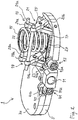
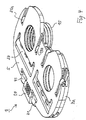
- Fig. 1 - 4th show in different views and different states a ligament-tensioning device 1, wherein Fig. 1 this interacts with a positioning tool.
- the ligament-tensioning device 1 comprises an approximately kidney-shaped distal abutment plate 5 in plan view and two of these proximal abutment plates 7 and 9, which are parallel and approximately half overlapping each, each comprising a lower part 7a, 9a and an upper part 7b, 9b.
- cylindrical recesses 11 are provided as engagement sections on the frontal side edges of the distal and proximal abutment plates. (In Fig. 1 thereof are the recesses in the proximal contact plates, more precisely: the upper parts 7b, 9b, shown during Fig. 2 the central recess 11 in the distal abutment plate 5 shows.)
- proximal bearing plates 7 and 9 are each connected to one another via a scissors guide 13 and biased against each other by a steel compression spring 15 as a spring element.
- the coil spring 15 is seated in an adapted circular recess 17 on the upper side of the distal abutment plate 5; a similar (not shown) storage is provided on the underside of each associated proximal abutment plate.
- the scissors guide 13 comprises a medial and lateral scissors articulation 19 and 21, each of which comprises two legs 19a, 19b and 21a, 21b which are rotatably connected via a rotation axis 23 or 25.
- the legs 19a, 21a are integrally formed via a bridge or connecting rod 27 connected at one end to each other, while in their other end in each case a sliding pin or pin 29a and 31a for connection to the (in Fig. 2 and 3 omitted) lower part 9a of the second abutment plate is inserted.
- one end of the legs 19b, 21b is connected via a connecting rod 33 inserted perpendicular to the extension plane, which projects beyond the medial or lateral outer side of the respective leg and forms further (not separately designated) sliding pins there.
- a separate sliding pin 29b and 31b is provided at the opposite ends of the legs 19b, 21b.
- These slide pins 29b, 31b engage (as best in FIG Fig. 3 can be seen) in correspondingly dimensioned, in the position of use of the ligament-tensioning device dorsal-ventral grooves 35, 37 of the distal abutment plate 5 and fix the scissors hereby slidably in the distal abutment plate 5.
- As in the lower part 7a of the first proximal abutment plate 7 representing Section of Fig. 3 can be seen beginning to see - see detail "A" -, in the proximal contact plates a corresponding, not separately numbered groove structure is provided.
- Fig. 2 how best in Fig. 2 to recognize, on the ventral side edge (leading edge) of the distal abutment plate 5 on both sides of a cylindrical recess 11 containing extension two pivoting hook elements 41, 43 are mounted, each having an Allen-engaging portion 41a and 43a and a molded hook portion 41b and 43b.
- the hook sections engage as in Fig. 2 can be seen in the region of the first proximal contact plate, in a corresponding to the hook shape shaped recess on the upper side of the respective bearing plate lower part a - wherein in Fig. 2 only the recess 45 is shown in the lower part 7a of the first proximal contact plate.
- the proximal abutment plates are kept at a minimum distance from the distal abutment plate.
- this lock is released, and the respective proximal contact plate can move away from the distal abutment plate under the bias of the associated compression spring 15 until its movement in force equilibrium with the on-site capsule. / Ligament tension comes to a standstill.
- a cylindrical coil spring 15 is shown, shows Fig. 5 as a modification, a double-conical coil spring 15 ', due to their lower in the tensioned state height at the ligament-tensioning device 1 after Fig. 1 - 4th can preferably be used.
- the slope of the winding in the lower and upper regions of larger diameter be lower than in the middle range, so that a perfect spring action over the entire stroke is guaranteed.
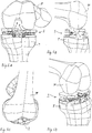
- the above-described ligament-tensioning device 1 is designed for use in a knee joint, and in Figs. 6A-6D This state of use is shown in different views. Good to see the adaptation of the dimensions, in particular the length / width ratio and the execution of the two proximal bearing plates 7, 9 on the anatomical conditions of the knee joint and especially the overall dimensions and size relations of the tibia T and the (resected) femur F.
- a ligament-tensioning device 1 'with a coupled sizer 47 is shown.
- An sizer is known to be used for intraoperative coupling of the tibia and femur in flexion such that axis transmission of the tibial axis can be made taking into account the ligament tension on the femur. It can also be used to define the optimal size and position of a knee implant in anterior-posterior direction and in rotation. The technical features of the sizer are not the subject of the present invention and are therefore not described here.
- connecting means between the ligament-tensioning device 1 'and the sizer 47 namely two clamp-like extensions or connecting straps 49a, 49b on the distal abutment plate 5, which overlap the proximal abutment plates (not designated here) on a lateral edge of the same and connect to a base 51 of the sizer 47.
- the embodiment of the invention is not limited to the embodiment described here and the last-mentioned modification of the spring element, but is also possible in a variety of modifications that are within the scope of professional action.
- a scissors guide which is arranged rotated relative to the embodiment shown by 90 ° and in the rest of a part of the sliding pins or spigots can also be formed as a bearing pin for stationary fixation of a respective leg end in the associated contact plate ,
- the upper parts may also be omitted, and numerous degrees of freedom exist with regard to the exact shape and dimensional relationships of the abutment plates.
Description
Die Erfindung betrifft ein Bänderspanngerät zum Einsatz bei der Implantation von Gelenk- oder Skelettimplantaten nach dem Oberbegriff des Anspruchs 1.The invention relates to a ligament-tensioning device for use in the implantation of joint or skeletal implants according to the preamble of
Bänderspannvorrichtungen mit dieser Funktion sind bekannt. So ist etwa aus der
Aus der
Aus der
Die bekannten Bänderspannvorrichtungen weisen im Gebrauch nach den jetzt vorliegenden Erfahrungen noch bestimmte Nachteile auf. Diese betreffen insbesondere die erwünschte exakte Ausrichtung zwischen den einander gegenüberliegenden Auflageplatten und den mit einer hydraulischen Antriebsvorrichtung verbundenen Aufwand. Zudem muss das jeweilige Gelenk bei Einsatz der bekannten Bänderspanngeräte offen gehalten werden, da wesentliche Teile der Vorrichtung herausragen.The known ligament-tensioning devices, in use according to the present experience, still have certain disadvantages. These relate in particular to the desired exact alignment between the opposing support plates and associated with a hydraulic drive device effort. In addition, the respective joint must be kept open when using the known ligament tensioning devices, since essential parts of the device protrude.
Der Erfindung liegt daher die Aufgabe zugrunde, ein unaufwendiges und den Anforderungen der Praxis in zuverlässiger Weise genügendes, verbessertes Bänderspanngerät mit vielseitigen Einsatzmöglichkeiten bereitzustellen.The invention is therefore based on the object to provide an inexpensive and the requirements of practice in a reliable manner sufficient, improved ligament-tensioning device with versatile applications.
Diese Aufgabe wird durch ein Bänderspanngerät mit den Merkmalen des Anspruchs 1 gelöst. Zweckmäßige Fortbildungen des Erfindungsgedankens sind Gegenstand der abhängigen Ansprüche.This object is achieved by a ligament-tensioning device having the features of
Die Erfindung schließt den wesentlichen Gedanken ein, in das jeweilige Gelenk vollständig einfügbares Bänderspanngerät bereitzustellen, welches es ermöglicht, die Gelenkkapsel nach Einsetzen wieder zu schließen. Hierzu sind insbesondere die Anlageplatten in Anpassung an das jeweilige Gelenk - etwa ein Kniegelenk - zu dimensionieren, und überstehende Teile (wie etwa beim Stand der Technik hervorstehende Handgriffe bzw. Hebel oder Hydraulikleitungen) sind weitestgehend zu vermeiden. Insofern schließt die Erfindung des Gedanken des Vorsehens eines rein internen Antriebes bzw. interner Verschiebemittel zur Relativverschiebung der einander gegenüberliegenden Anlageplatten ein.The invention includes the essential idea to provide in the respective joint fully insertable ligament-tensioning device, which makes it possible to close the joint capsule after insertion again. For this purpose, in particular the bearing plates in adaptation to the respective joint - such as a knee joint - to dimension, and protruding parts (such as in the prior art protruding handles or levers or hydraulic lines) are to be avoided as far as possible. In this respect, the invention includes the idea of providing a purely internal drive or internal displacement means for the relative displacement of the opposing contact plates.
Die Erfindung schließt den Gedanken ein, eine in ventral-dorsaler wie auch medial-lateraler Richtung präzise Parallelführung zwischen distaler Anlageplatte und den proximalen Anlageplatten bereitzustellen. Dies wird durch eine geeignete Führung nach dem Scheren-Prinzip realisiert. Nur beispielhaft, nicht erfindungsgemäß, kommen aber auch andere Zwei-Ebenen-Parallelführungen, z.B. unter Verwendung zweier nicht achsenparallel zueinander (insbesondere einen Winkel von 90° zueinander einschließender) Scharniergelenke.The invention includes the idea of providing a precise parallel guidance between the distal abutment plate and the proximal abutment plates in anterior-dorsal as well as medial-lateral direction. This is realized by a suitable guidance according to the scissors principle. By way of example only, not according to the invention, but also other two-level parallel guides, eg using two non-axis parallel to each other (in particular an angle of 90 ° to each other enclosing) hinge joints.
Weiterhin schließt die Erfindung, in einer relativ selbstständigen Ausprägung, den Gedanken ein, als Antrieb zum Voneinander-Abstoßen zwischen der distalen Anlageplatte und den proximalen Anlageplatten jeweils ein separates Antriebselement vorzusehen, und zwar ein ohne Hilfsenergie auskommendes Antriebselement. In dieser Ausprägung gehört zur Erfindung schließlich der Gedanke, jeder proximalen Anlageplatte ein Federelement zuzuordnen, welches in einem Ausgangszustand, in dem die proximale Anlageplatte minimalen Abstand zur distalen Anlageplatte hat, die Antriebsenergie gespeichert hält und sie beim In-Funktion-Setzen des Bänderspanners zur Abstandvergrößerung freigibt. Schließlich gehört zur Erfindung, in bevorzugter Ausführung noch der Gedanke, diesem Federelement bzw. den gegenüberliegenden Anlageplatten eine Verriegelung zur lösbaren Fixierung in der Ausgangslage zuzuordnen.Furthermore, the invention includes, in a relatively independent form, the idea of providing a separate drive element for driving off each other between the distal abutment plate and the proximal abutment plates, namely a drive element without auxiliary energy. In this form, the invention finally includes the idea of associating with each proximal abutment plate a spring element which, in an initial state in which the proximal abutment plate is at a minimum distance from the distal abutment plate, stores the drive energy and, when the ligament adjuster is put into operation, increases the distance releases. Finally belongs to the invention, in a preferred embodiment nor the idea to assign this spring element or the opposite bearing plates a lock for releasable fixation in the starting position.
Grundsätzlich kommt aber auch ein Antrieb mit Hilfsenergie, etwa ein elektromotorischer, elektromagnetischer, hydraulischer oder pneumatischer Antrieb, in Betracht. Dieser kann beide proximale Anlageplatten gemeinsam antreiben, wobei deren Endlage sich im Kräftegleichgewicht mit der umgebenden Kapsel- /Bänderstruktur unterschiedlich einstellen kann. Die genannten Antriebsmittel können aber auch separat für jede proximale Anlageplatte vorgesehen sein.In principle, however, is also a drive with auxiliary power, such as an electric motor, electromagnetic, hydraulic or pneumatic drive, into consideration. This can drive both proximal abutment plates together, with their end position can be set in the balance of power with the surrounding capsule / ligament structure differently. The said drive means may also be provided separately for each proximal contact plate.
An dieser Stelle ist darauf hinzuweisen, dass in der vorliegenden Beschreibung und den anhängenden Ansprüchen die Termini "distale Anlageplatte" und "proximale Anlageplatte" unter Bezugnahme auf bevorzugte Gebrauchslagen des Bänderspanners, etwa beim Einsatz im Knie, benutzt werden. Für diesen Einsatzfall könnte man synonym auch von einer Tibia-Anlageplatte bzw. Femur-Anlageplatte sprechen; es sind jedoch ausdrücklich auch Vertauschungen der Anlageplatten im Hinblick auf ihre entferntere oder nähere Lage zum Körperzentrum, (distal bzw. proximal) als zur Erfindung gehörig zu verstehen.It should be noted that in this specification and the appended claims, the terms "distal abutment plate" and "proximal abutment plate" are used with reference to preferred operating positions of the ligament-tensioner, such as when used in the knee. For this application, one could synonymously also speak of a tibial attachment plate or femur attachment plate; However, it is expressly permutations of the investment plates in terms of their distant or closer location to the body center, to understand (distal or proximal) as belonging to the invention.
In einer aus derseitiger Sicht bevorzugten Ausführung weist das Federelement ein Druckfederelement auf, das in einem Überdeckungsbereich der proximalen und distalen Anlageplatten angeordnet ist und sich gegen beide abstützt. Hierbei weist insbesondere das Federelement eine Stahl- oder Titan-Schraubenfeder mit geeigneter Federcharakteristik auf. Es zeichnet sich dabei aus durch eine Federsteifigkeit auf die auf, eine vorbestimmte Spannkraft abgestimmt ist, um insbesondere eine über seinen Hub im Wesentlichen konstante Spannkraft im Bereich zwischen 50 und 90 N, insbesondere von 70 N, bereitzustellen.In a preferred embodiment from the one side view, the spring element has a compression spring element which is arranged in a covering region of the proximal and distal abutment plates and is supported against both. In this case, in particular, the spring element on a steel or titanium coil spring with a suitable spring characteristic. It is characterized by a spring stiffness, which is tuned to a predetermined clamping force, in particular to provide over its stroke substantially constant clamping force in the range between 50 and 90 N, in particular of 70 N, to provide.
Im Hinblick auf die besonderen Anforderungen der Realisierung einer relativ hohen und konstanten Spannkraft einerseits und der Realisierung einer möglichst geringen Anfangs-Höhe des Federelementes im gespannten Zustand ist der Einsatz von hierauf zugeschnittenen Sonderbauformen der Druckfeder bevorzugt. Eine aus derzeitiger Sicht bevorzugte Bauform zeichnet sich dadurch aus, dass die Stahl- oder Titan-Schraubenfeder zur Vergrößerung des Hubes konisch oder doppelt-konisch ausgeführt ist und insbesondere eine zum lokalen Windungsdurchmesser indirekt proportionale Steigung aufweist. Der konische Verlauf des Federelementes ist dabei so gewählt, dass die Bauhöhe im gespannten Zustand sich gegenüber einer vergleichbaren Schraubenfeder mit zylindrischer Grundform wesentlich reduziert.In view of the special requirements of the realization of a relatively high and constant clamping force on the one hand and the realization of the lowest possible initial height of the spring element in the tensioned state, the use of tailored special designs of the compression spring is preferred. A preferred form from the current point of view is characterized in that the steel or titanium coil spring is designed to increase the stroke conical or double-conical and in particular has a slope proportional to the local coil diameter diagonal. The conical shape of the spring element is chosen so that the overall height in the tensioned state is substantially reduced compared to a comparable coil spring with a cylindrical basic shape.
In einer alternativen Ausführung weist das Federelement ein Biegefederelement auf, und zwar beispielsweise eine Stahl-Spiral- oder -Blattfeder.In an alternative embodiment, the spring element on a spiral spring element, namely, for example, a steel spiral or leaf spring.
Die als Parallelführung vorliegende Scherenführung weist bevorzugt zwei nahe gegenüberliegenden Enden der proximalen Anlageplatte angeordnete, also möglichst weit voneinander beabstandete Scherengelenke auf. In verschiedenen Ausführungen der Erfindung können diese in ventral-dorsaler Richtung (hintereinander) oder in medial-lateraler Richtung (nebeneinander) angeordnet sein. Eine vorteilhafte Ausführung der Scherenführung zeichnet sich dadurch aus, dass die Enden der Scherengelenke in Nuten der distalen bzw. proximalen Anlageplatte eingeschoben sind und jeweils ein Schenkel oder jeweils ein Ende beider Schenkel hierin durch senkrecht zur Nut-Erstreckungsrichtung verlaufende Lagerstifte drehfähig fixiert ist.The present as a parallel guide scissors guide preferably has two near opposite ends of the proximal contact plate arranged, so as far as possible from each other spaced scissor hinges. In various embodiments of the invention, these can be arranged in a ventral-dorsal direction (behind one another) or in a medial-lateral direction (next to one another). An advantageous embodiment of the scissor guide is characterized in that the ends of the scissors joints are inserted into grooves of the distal or proximal contact plate and one leg or one end of both legs is rotatably fixed therein by perpendicular to the groove extension direction extending bearing pins.
Eine zusätzlich verbesserte Führung und gegenseitige Fixierung der gegenüberliegenden Anlageplatten wird erreicht, indem an beiden Enden des freien Schenkels oder an dem jeweils freien Ende beider Schenkel ein Gleitstift zur Führung des jeweiligen Schenkels bzw. Endes in einer in Anpassung an den Gleitstift ausgearbeiteten Nut vorgesehen ist. Zur Erhöhung der Steifigkeit und einer noch weiter verbesserten Führung ist bevozugt auch vorgesehen, dass die Scherengelenke über mindestens einen am Ende jeweils einen Schenkels angebrachten Verbindungsstab miteinander verbunden sind.An additional improved guidance and mutual fixation of the opposite bearing plates is achieved by a sliding pin for guiding the respective leg or end is provided in a prepared in adaptation to the sliding pin groove at both ends of the free leg or at the respective free end of both legs. To increase the rigidity and even further improved guidance, it is also preferred that the scissor hinges are connected to one another via at least one connecting rod attached at the end of each leg.
Zur Anpassung an die konkreten anatomischen Gegebenheiten verschiedener Patienten ist weiterhin vorgesehen, dass die erste und zweite proximale Anlageplatte jeweils ein Ober- und Unterteil umfassen, wobei im Unterteil Mittel zur Halterung des Federelements und der Scherenführung vorgesehen sind und das Oberteil zur Vergrößerung der Dicke der jeweiligen Anlageplatte lösbar auf dem Unterteil fixiert ist. Das Bänderspanngerät kann hierbei mit einem Satz verschieden dicker Oberteile zur besonders präzisen Lösung der erwähnten Anpassungs-Aufgabe zum Einsatz kommen.To adapt to the specific anatomical conditions of different patients is further provided that the first and second proximal abutment plate each comprise an upper and lower part, wherein in the lower part means for holding the spring element and the scissor guide are provided and the upper part to increase the thickness of the respective Attachment plate is releasably fixed on the lower part. The ligament-tensioning device This can be used with a set of different thick tops for particularly precise solution of the mentioned adaptation task.
Die oben erwähnte Verriegelung wird in zweckmäßiger Weise dadurch gelöst, dass an der distalen Anlageplatte oder der ersten und zweiten proximalen Anlageplatte lösbare Verriegelungsmittel zur unabhängigen Verriegelung der ersten und zweiten proximalen Anlageplatte mit der distalen Anlageplatte in einem minimalen Abstand und mit einer maximalen Federspannung dieser gegenüber vorgesehen sind.The above-mentioned locking is conveniently accomplished by providing releasable locking means on the distal abutment plate or the first and second proximal abutment plates for independently locking the first and second proximal abutment plates to the distal abutment plate at a minimum distance and maximum spring tension therebetween are.
Eine bevorzugte Ausgestaltung ergibt sich dadurch, dass die Verriegelungsmittel jeweils eine an der jeweiligen Anlageplatte schwenkbar gelagerten und in die gegenüberliegende Anlageplatte eingreifenden Haken aufweisen, an dem ein erster Werkzeug-Eingriffsabschnitt zur Betätigung vorgesehen ist. Im Hinblick auf das auf dem Einsatzgebiet des vorgeschlagenen Bänderspanners verfügbare Werkzeug-Reservoir ist der Werkzeug-Eingriffsabschnitt bevorzugt zum Eingriff eines Inbus-Werkzeugs, etwa einem 3,5 mm-Inbus, ausgeführt.A preferred embodiment results from the fact that the locking means each have a pivotally mounted on the respective bearing plate and engaging in the opposite bearing plate hook on which a first tool engagement portion is provided for actuation. In view of the tool reservoir available in the field of application of the proposed band tensioner, the tool engagement portion is preferably designed to engage an Allen tool, such as a 3.5 mm Allen key.
In einer ersten Ausführung der Verriegelungsmittel mit schwenkbaren Haken ist vorgesehen, dass aus dem Material der ersten und zweiten proximalen Anlageplatte in räumlicher Zuordnung zum an der distalen Anlageplatte angelenkten Haken ein Eingriffsabschnitt für diesen ausgearbeitet ist.In a first embodiment of the locking means with pivotable hook is provided that from the material of the first and second proximal abutment plate in spatial association with the hinged to the distal abutment plate hook an engagement portion is prepared for this.
Eine zweite Ausführung sieht vor, dass jeweils ein erster Lagerstift eines Scherengelenks der ersten und zweiten proximalen Anlageplatte über deren Außenrand vorsteht und relativ zum an der distalen Anlageplatte schwenkbaren Haken so angeordnet ist, dass er das Widerlager der Verriegelungsmittel bildet. Hierbei - oder auch unabhängig davon - sieht eine sinnreiche konstruktive Lösung des weiteren vor, dass jeweils ein zweiter Lagerstift eines Scherengelenks der ersten und zweiten proximalen Anlageplatte über deren Außenrand vorsteht und relativ zum an der distalen Anlageplatte schwenkbaren Haken so angeordnet ist, dass er dessen Schwenkachse bildet.A second embodiment provides that in each case a first bearing pin of a scissors joint of the first and second proximal abutment plate protrudes beyond its outer edge and is arranged relative to the pivotable on the distal abutment plate hooks so that it forms the abutment of the locking means. Here - or independently thereof - provides an ingenious constructive solution further, that in each case a second bearing pin of a scissors joint of the first and second proximal abutment plate protrudes beyond the outer edge and is arranged relative to the pivotable on the distal abutment plate hook so that it the pivot axis forms.
Da wegen der hohen erforderlichen Kräfte auch zur Positionierung des Bänderspanners am Einsatzort zweckmäßigerweise ein Werkzeug eingesetzt wird, ist bevorzugt an den Seitenkanten der distalen Anlageplatte und der ersten und zweiten proximalen Anlageplatte jeweils ein zweiter Werkzeug-Eingriffsabschnitt, insbesondere eine zylindrische Ausnehmung, zum Eingriff eines Positionierungswerkzeugs vorgesehen. Das Vorsehen eines separaten Werkzeuges ist im Hinblick auf die Realisierung eines vollständig gelenkintegrierbaren Bänderspanners von besonderem Vorteil.Since a tool is expediently also used for positioning the ligament tensioner on site because of the high forces required, a second tool engagement section, in particular a cylindrical recess, for engaging a positioning tool is preferably provided on the side edges of the distal abutment plate and the first and second proximal abutment plates intended. The provision of a separate tool is in view of the realization of a completely joint integrated ligament tensioner of particular advantage.
Eine weitere zweckmäßige Ausführung sieht eine Ausbildung zum lösbaren Ankoppeln eines Sizers vor, welcher das proximale und distale Skelettteil in Beugung derart koppelt, dass eine Achsenübertragung von dem einen Skelettteil auf das andere unter Berücksichtigung der Bänderspannung möglich ist. Grundsätzlich umfasst das Ankoppeln auch ein einfaches Anlegen an geeignet bereitgestellte Anlageflächen, bevorzugt jedoch Verbindungsmittel zur Fixierung des Sizers an der distalen Anlageplatte. In einer aus derzeitiger Sicht zweckmäßigen Ausführung umfassen die Verbindungsmittel zwei klammerartige Fortsätze an der distalen Anlageplatte, welche jeweils eine Seitenkante der proximalen Anlageplatten umgreifend zu einer Grundplatte des Sizers geführt sind.A further expedient embodiment provides for a design for releasably coupling a sizer, which flexes the proximal and distal skeleton parts in such a way that an axis transmission from one skeleton part to the other is possible taking into account the ligament tension. Basically, the coupling also includes a simple application to suitably provided contact surfaces, but preferably connecting means for fixing the sizer to the distal abutment plate. In an embodiment which is expedient from a current point of view, the connecting means comprise two clamp-like extensions on the distal abutment plate, which each have a side edge of the proximal abutment plates guided around a base plate of the sizer.
Als zum Schutzbereich der Erfindung gehörig sollen auch Anordnungen aus dem vorgeschlagenen Bänderspanngerät und einem angepassten Positionierungswerkzeug und/oder einem daran angepassten Sizer angesehen werden.As belonging to the scope of the invention, arrangements of the proposed ligament-tensioning device and a customized positioning tool and / or an adapted sizer should also be considered.
Vorteile und Zweckmäßigkeiten der Erfindung ergeben sich im übrigen aus den abhängigen Ansprüchen sowie der nachfolgenden Beschreibung bevorzugter Ausführungsbeispiele anhand der Figuren. Von diesen zeigen:
- Fig. 1
- eine perspektivische Ansicht eines erfindungsgemäßen Bänderspanngerätes ventral schräg von oben, teilweise als Explosionsdarstellung, mit angesetztem Positionierungswerkzeug,
- Fig. 2
- eine perspektivische Ansicht des Bänderspanngerätes nach
Fig. 1 ventral schräg von oben, mit abgenommener zweiter proximaler Anlageplatte und den zugehörigen Verschiebemitteln im voll ausgefahrenen Zustand, - Fig. 3
- eine perspektivische Ansicht des Bänderspanngerätes nach
Fig. 1 und2 , mit abgenommener zweiter proximaler Anlageplatte und Verschiebemitteln in Zwischenstellung, dorsal schräg von oben, - Fig. 4
- eine perspektivische Ansicht des Bänderspanngerätes nach
Fig. 1 - 3 , mit abgenommener zweiter proximaler Anlageplatte, ventral schräg von unten, - Fig. 5
- eine perspektivische Darstellung einer als Federelement beim Bänderspanngerät nach
Fig. 1 - 4 einsetzbaren Schraubenfeder in doppelt-konischer Ausführung, - Fig. 6A - 6D
- verschiedene Ansichten des Bänderspanngerätes nach
Fig. 1 in seinem in ein Kniegelenk eingesetzten Gebrauchszustand, und - Fig. 7A - 7D
- verschiedene Ansichten des Bänderspanngerätes nach
Fig. 1 in seinem in ein Kniegelenk eingesetzten Gebrauchszustand, mit einem angekoppelten Sizer.
- Fig. 1
- a perspective view of a ligament-tensioning device according to the invention ventral obliquely from above, partially exploded view, with attached positioning tool,
- Fig. 2
- a perspective view of the ligament-tensioning device according to
Fig. 1 ventral obliquely from above, with removed second proximal abutment plate and the associated displacement means in the fully extended state, - Fig. 3
- a perspective view of the ligament-tensioning device according to
Fig. 1 and2 , with removed second proximal abutment plate and displacement means in intermediate position, dorsally obliquely from above, - Fig. 4
- a perspective view of the ligament-tensioning device according to
Fig. 1-3 , with removed second proximal abutment plate, anteriorly obliquely from below, - Fig. 5
- a perspective view of a spring element in the ligament-tensioning device according to
Fig. 1 - 4th insertable coil spring in double conical design, - Figs. 6A-6D
- different views of the ligament-tensioning device
Fig. 1 in his state of use inserted in a knee joint, and - Figs. 7A-7D
- different views of the ligament-tensioning device
Fig. 1 in his state of use inserted in a knee joint, with a coupled sizer.
Das Bänderspanngerät 1 umfasst eine in der Draufsicht annähernd nierenförmige distale Anlageplatte 5 und zwei dieser parallel gegenüberliegende und sie jeweils annähernd hälftig überdeckende proximale Anlageplatten 7 und 9, die jeweils ein Unterteil 7a, 9a und ein Oberteil 7b, 9b umfassen. Zur Positionierung des Bänderspanngerätes 1 mit Hilfe des Positionierungswerkzeuges 3 sind an den frontalen Seitenkanten der distalen und proximalen Anlageplatten jeweils zylindrische Ausnehmungen 11 als Eingriffsabschnitte vorgesehen. (In
Die proximalen Anlageplatten 7 und 9 (oder, genauer: deren Unterteile 7a, 9a) sind jeweils über eine Scherenführung 13 miteinander verbunden und durch eine Stahl-Druckfeder 15 als Federelement gegeneinander vorgespannt. Wie am besten in
Die Scherenführung 13 umfasst ein mediales und laterales Scherengelenk 19 bzw. 21, die jeweils zwei über eine Drehachse 23 bzw. 25 drehbar verbundene Schenkel 19a, 19b bzw. 21a, 21b umfassen. Die Schenkel 19a, 21a sind über eine einstückig angeformte Brücke bzw. Verbindungsstange 27 an jeweils einem Ende miteinander verbunden, während in ihr anderes Ende jeweils ein Gleitstift bzw. -zapfen 29a bzw. 31a zur Verbindung mit dem (in
An den gegenüberliegenden Enden der Schenkel 19b, 21b ist jeweils wiederum ein separater Gleitstift 29b bzw. 31b vorgesehen. Diese Gleitstifte 29b, 31b greifen (wie am besten in
Wie am besten in
Während in den
Da oben beschriebene Bänderspanngerät 1 ist zum Einsatz in einem Kniegelenk ausgebildet, und in
In
Die Ausführung der Erfindung beschränkt sich nicht auf das hier erläuterte Ausführungsbeispiel und die zuletzt erwähnte Modifikation des Federelementes, sondern ist ebenso in einer Vielzahl von Abwandlungen möglich, die im Rahmen fachgemäßen Handelns liegen. So ist sie insbesondere auch mit einer Scherenführung möglich, die gegenüber der dargestellten Ausführungsform um 90° gedreht angeordnet ist und bei der im übrigen ein Teil der Gleitstifte bzw. -zapfen zugleich als Lagerzapfen zur ortsfesten Fixierung jeweils eines Schenkelendes in der zugehörigen Anlageplatte ausgebildet sein kann. In einer solchen Ausführung ist es zudem möglich, jeweils einen solchen Lagerzapfen zugleich als Schwenkachse der schwenkbaren Verriegelungshaken zu nutzen. Weiterhin können bei den proximalen Anlageplatten die Oberteile auch fortgelassen sein, und zahlreiche Freiheitsgrade bestehen hinsichtlich der exakten Form und Abmessungs-Relationen der Anlageplatten.The embodiment of the invention is not limited to the embodiment described here and the last-mentioned modification of the spring element, but is also possible in a variety of modifications that are within the scope of professional action. Thus, it is particularly possible with a scissors guide, which is arranged rotated relative to the embodiment shown by 90 ° and in the rest of a part of the sliding pins or spigots can also be formed as a bearing pin for stationary fixation of a respective leg end in the associated contact plate , In such an embodiment, it is also possible to use such a bearing pin at the same time as a pivot axis of the pivotable locking hooks. Furthermore, in the case of the proximal abutment plates, the upper parts may also be omitted, and numerous degrees of freedom exist with regard to the exact shape and dimensional relationships of the abutment plates.
- 11
- BänderspanngerätStrapsTie device
- 22
- Positionierungswerkzeugposition tool
- 55
- distale Anlageplattedistal abutment plate
- 7, 97, 9
- proximale Anlageplattenproximal abutment plates
- 7a, 9a7a, 9a
- Unterteile der proximalen AnlageplattenLower parts of the proximal abutment plates
- 7b, 9b7b, 9b
- Oberteile der proximalen AnlageplattenTops of the proximal abutment plates
- 1111
- zylindrische Ausnehmungcylindrical recess
- 1313
- Scherenführungscissors leadership
- 1515
- zylindrische Schraubenfedercylindrical coil spring
- 15'15 '
- doppelt-konische Schraubenfederdouble conical coil spring
- 1717
- kreisförmige Ausnehmungcircular recess
- 1919
- mediales Scherengelenkmedial scissors joint
- 19a, 19b19a, 19b
- Schenkel des medialen ScherengelenksThighs of the medial scissors joint
- 2121
- laterales Scherengelenklateral scissors joint
- 21a, 21b21a, 21b
- Schenkel des lateralen ScherengelenksLegs of the lateral scissors joint
- 2323
- Drehachse des medialen ScherengelenksRotational axis of the medial scissors joint
- 2525
- Drehachse des lateralen ScherengelenksRotational axis of the lateral scissors joint
- 2727
- Verbindungsstangeconnecting rod
- 29a, 29b, 31a, 31b29a, 29b, 31a, 31b
- Gleitstifteslide pins
- 35, 3735, 37
- Nutengroove
- 41, 4341, 43
- Hakenelementehook elements
- 41a, 43a41a, 43a
- Inbus-EingriffsabschnitteAllen engaging portions
- 41b, 43b41b, 43b
- angeformte Hakenabschnittemolded hook sections
- 4545
- Ausnehmungrecess
- 4747
- SizerSizer
- 49a, 49b49a, 49b
- Fortsätzeprojections
- 5151
- Grundplattebaseplate
Claims (29)
- A ligament-tensioning device (1) for activation of the ligament and/or capsule system during the implantation of a joint implant, comprising a distal bearing plate (5) to bear against a distal skeletal part and a first and second proximal bearing plate (7, 9), each of which at least partially overlaps said distal bearing plate (5) in a first usage position, to bear against a proximal skeletal part and means for relative displacement of said proximal bearing plates (7, 9) to increase their spacing from the distal bearing plate,
wherein all the essential components of said ligament-tensioning device, in particular the distal bearing plate (5) and first and second proximal bearing plate (7, 9) are dimensioned such that they can be accommodated between portions of the distal and proximal skeletal parts adjacent to the joint in such a manner that a joint capsule can be closed again after insertion of the ligament-tensioning device,
characterized in that
the displacement means comprises scissor-type guide (13) which supports the respective proximal bearing plates in a parallel position with respect to the distal bearing plate, which is configured to be torsionally stiff construction between the distal bearing plate and the respective proximal bearing plate in such a manner that said guide provides precise parallel guidance between the distal bearing plate and the proximal bearing plates in both the ventral-dorsal and the medial-lateral directions. - The ligament-tensioning device (1) according to claim 1,
characterized by
exclusively internal means for the relative displacement of the proximal bearing plates with respect to the distal bearing plate. - The ligament-tensioning device (1) according to one of the preceding claims,
characterized in that
said displacement means comprises at least one spring element (15) to drive said proximal bearing plates, which spring element keeps the drive energy stored in a starting state in which said proximal bearing plates (7, 9) have a minimum spacing from said distal bearing plate (5), and releases said energy to increase the spacing when the ligament-tensioning device is actuated. - The ligament-tensioning device (1) according to claim 3,
characterized in that
the displacement means has, assigned to each of said first and second bearing plates, a spring element (15) for driving the proximal bearing plates. - The ligament-tensioning device (1) according to claim 3 or 4,
characterized in that
the or each spring element (15) is configured in such a manner that it is lockable. - The ligament-tensioning device (1) according to one of claims 3 to 5,
characterized in that
the spring element (15) comprises a compression spring element arranged in a region of overlap between said proximal and distal bearing plates. - The ligament-tensioning device (1) according to claim 6,
characterized in that
the spring element (15) comprises a steel or titanium helical spring which is designed to be conical or double-conical in order to increase the travel and in particular has a pitch indirectly proportional to the local winding diameter. - The ligament-tensioning device (1) according to claim 3 or 4,
characterized in that
the spring element (15) comprises a flexural spring element. - The ligament-tensioning device (1) according to claim 8,
characterized in that
said spring element (15) comprises a metal spiral spring or a leaf spring. - The ligament-tensioning device (1) according to one of the preceding claims,
characterized in that
the
scissor-type guide (13) comprises two scissor joints arranged close to opposite ends of said proximal bearing plate. - The ligament-tensioning device (1) according to claim 10,
characterized in that
the ends of the scissor joints are inserted in grooves in said distal or proximal bearing plates and one limb or one end of one limb of each joint is rotatably fixed herein by bearing pins or slide pegs extending perpendicular to the direction of extension of the groove. - The ligament-tensioning device (1) according to claim 11,
characterized in that
at both ends of the free limb or at the respectively free end of both limbs there is provided a slide peg for guiding the respective limb or end in a groove in said distal or proximal bearing plate, which groove is formed to match the slide peg. - The ligament-tensioning device (1) according to one of claims 10 to 12,
characterized in that
said scissor joints are joined to one another by a connecting rod mounted at the end of respectively one limb. - The ligament-tensioning device (1) according to one of the preceding claims,
characterized in that
said first and second proximal bearing plates (7, 9) each comprise an upper and a lower part (7a, 7b, 9a, 9b), wherein means for mounting the scissor-type guide (13) and optionally the spring element (15) are provided in the lower part (7a, 9a) and the upper part (7b, 9b) is fixed releasably on the lower part to increase, as desired, the thickness of the respective bearing plate. - The ligament-tensioning device (1) according to one of the preceding claims,
characterized in that
releasable locking means for independent locking of said first and second proximal bearing plates to said distal bearing plate at a minimum spacing and with respect thereto are provided on the distal bearing plate (5) or the first and second proximal bearing plate (7, 9). - The ligament-tensioning device (1) according to claim 15,
characterized in that
said locking means has respectively one hook pivotally mounted on the respective bearing plate and engaging in the opposing bearing plate, on which hook a first tool-engagement portion for actuation is provided. - The ligament-tensioning device (1) according to claim 16,
characterized in that
the first tool-engagement portion is formed for engagement of a hex key. - The ligament-tensioning device (1) according to claim 16 or 17,
characterized in that
from the material of said first and second proximal bearing plate (7, 9), in spatial association with the hook articulated on said distal bearing plate (5), there is formed an engagement portion for the hook. - The ligament-tensioning device (1) according to one of claims 16 to 18,
characterized in that
in each case a first bearing peg of a scissor joint of the first or second proximal bearing plate (7, 9) projects beyond the outer edge thereof and is so arranged relative to the hook pivotally mounted on said distal bearing plate (5) that it forms the counter-bearing of the locking means. - The ligament-tensioning device (1) according to one of claims 16 to 19,
characterized in that
in each case a second bearing peg of a scissor joint of said first or second proximal bearing plate (7, 9) projects beyond the outer edge thereof and is so arranged relative to the hook pivotally mounted on said distal bearing plate (5) that it forms a pivot axis thereof. - The ligament-tensioning device (1) according to one of the preceding claims,
characterized in that
on the side edges of the distal bearing plate (5) and of the first and second proximal bearing plate (7, 9) there is provided respectively one second tool-engagement portion, in particular a cylindrical recess, for engagement of a positioning tool. - The ligament-tensioning device (1) according to one of claims 3 to 21,
characterized by
a spring element (15) matched in spring constant to a predetermined tensioning force, which in particular provides a tensioning force that is substantially constant over its travel, in the range of between 50 and 90 N, in particular 70 N. - The ligament-tensioning device (1) according to one of the preceding claims,
characterized in that
the length/width ratio, i.e. the dimension in the medial-lateral direction with respect to that in the ventral-dorsal direction, is matched to the proportions of a resected portion of the adjacent skeletal part close to the joint. - The ligament-tensioning device (1) according to one of the preceding claims,
characterized by
a configuration matched to a knee joint, the adjacent skeletal parts being a femur and a tibia. - The ligament-tensioning device (1) according to claim 23 and 24,
characterized in that
the length/width ratio is 3/2 in accordance with that of a proximal resected tibia. - The ligament-tensioning device (1) according to one of the preceding claims,
characterized by
a configuration for releasable coupling of a sizer, which couples the proximal and distal skeletal parts in flexion in such a manner that axial transmission from the one skeletal part to the other is possible taking account of the ligament tension. - The ligament-tensioning device (1) according to claim 26,
characterized by
connecting means for fixing the sizer on the distal bearing plate (5). - The ligament-tensioning device (1) according to claim 27,
characterized in that
the connecting means comprise two clip-like extensions on the distal bearing plate which, each engaging around a side edge of the proximal bearing plates (7, 9), are guided to a base plate of the sizer. - Arrangement comprising a ligament-tensioning system (1) according to one of the preceding claims and a sizer which in particular are designed to match a knee joint and are releasably coupled together.
Applications Claiming Priority (2)
| Application Number | Priority Date | Filing Date | Title |
|---|---|---|---|
| DE102005049851A DE102005049851A1 (en) | 2005-10-18 | 2005-10-18 | StrapsTie device |
| PCT/EP2006/010052 WO2007045460A2 (en) | 2005-10-18 | 2006-10-18 | Ligament tensioning device |
Publications (2)
| Publication Number | Publication Date |
|---|---|
| EP1937155A2 EP1937155A2 (en) | 2008-07-02 |
| EP1937155B1 true EP1937155B1 (en) | 2018-09-26 |
Family
ID=37681381
Family Applications (1)
| Application Number | Title | Priority Date | Filing Date |
|---|---|---|---|
| EP06806368.4A Active EP1937155B1 (en) | 2005-10-18 | 2006-10-18 | Ligament tensioning device |
Country Status (4)
| Country | Link |
|---|---|
| US (2) | US9216097B2 (en) |
| EP (1) | EP1937155B1 (en) |
| DE (1) | DE102005049851A1 (en) |
| WO (1) | WO2007045460A2 (en) |
Families Citing this family (85)
| Publication number | Priority date | Publication date | Assignee | Title |
|---|---|---|---|---|
| US7658751B2 (en) | 2006-09-29 | 2010-02-09 | Biomet Sports Medicine, Llc | Method for implanting soft tissue |
| US8118836B2 (en) | 2004-11-05 | 2012-02-21 | Biomet Sports Medicine, Llc | Method and apparatus for coupling soft tissue to a bone |
| US7905904B2 (en) | 2006-02-03 | 2011-03-15 | Biomet Sports Medicine, Llc | Soft tissue repair device and associated methods |
| US9017381B2 (en) | 2007-04-10 | 2015-04-28 | Biomet Sports Medicine, Llc | Adjustable knotless loops |
| US7909851B2 (en) | 2006-02-03 | 2011-03-22 | Biomet Sports Medicine, Llc | Soft tissue repair device and associated methods |
| US8128658B2 (en) | 2004-11-05 | 2012-03-06 | Biomet Sports Medicine, Llc | Method and apparatus for coupling soft tissue to bone |
| US8361113B2 (en) | 2006-02-03 | 2013-01-29 | Biomet Sports Medicine, Llc | Method and apparatus for coupling soft tissue to a bone |
| US9801708B2 (en) | 2004-11-05 | 2017-10-31 | Biomet Sports Medicine, Llc | Method and apparatus for coupling soft tissue to a bone |
| US8840645B2 (en) | 2004-11-05 | 2014-09-23 | Biomet Sports Medicine, Llc | Method and apparatus for coupling soft tissue to a bone |
| US8303604B2 (en) | 2004-11-05 | 2012-11-06 | Biomet Sports Medicine, Llc | Soft tissue repair device and method |
| US8137382B2 (en) | 2004-11-05 | 2012-03-20 | Biomet Sports Medicine, Llc | Method and apparatus for coupling anatomical features |
| US8298262B2 (en) | 2006-02-03 | 2012-10-30 | Biomet Sports Medicine, Llc | Method for tissue fixation |
| US7749250B2 (en) | 2006-02-03 | 2010-07-06 | Biomet Sports Medicine, Llc | Soft tissue repair assembly and associated method |
| US8088130B2 (en) | 2006-02-03 | 2012-01-03 | Biomet Sports Medicine, Llc | Method and apparatus for coupling soft tissue to a bone |
| US8998949B2 (en) | 2004-11-09 | 2015-04-07 | Biomet Sports Medicine, Llc | Soft tissue conduit device |
| US8936621B2 (en) | 2006-02-03 | 2015-01-20 | Biomet Sports Medicine, Llc | Method and apparatus for forming a self-locking adjustable loop |
| US8968364B2 (en) | 2006-02-03 | 2015-03-03 | Biomet Sports Medicine, Llc | Method and apparatus for fixation of an ACL graft |
| US8652172B2 (en) | 2006-02-03 | 2014-02-18 | Biomet Sports Medicine, Llc | Flexible anchors for tissue fixation |
| US8506597B2 (en) | 2011-10-25 | 2013-08-13 | Biomet Sports Medicine, Llc | Method and apparatus for interosseous membrane reconstruction |
| US8771352B2 (en) | 2011-05-17 | 2014-07-08 | Biomet Sports Medicine, Llc | Method and apparatus for tibial fixation of an ACL graft |
| US9078644B2 (en) | 2006-09-29 | 2015-07-14 | Biomet Sports Medicine, Llc | Fracture fixation device |
| US8597327B2 (en) | 2006-02-03 | 2013-12-03 | Biomet Manufacturing, Llc | Method and apparatus for sternal closure |
| US11259792B2 (en) | 2006-02-03 | 2022-03-01 | Biomet Sports Medicine, Llc | Method and apparatus for coupling anatomical features |
| US9149267B2 (en) | 2006-02-03 | 2015-10-06 | Biomet Sports Medicine, Llc | Method and apparatus for coupling soft tissue to a bone |
| US8652171B2 (en) | 2006-02-03 | 2014-02-18 | Biomet Sports Medicine, Llc | Method and apparatus for soft tissue fixation |
| US8251998B2 (en) | 2006-08-16 | 2012-08-28 | Biomet Sports Medicine, Llc | Chondral defect repair |
| US8574235B2 (en) | 2006-02-03 | 2013-11-05 | Biomet Sports Medicine, Llc | Method for trochanteric reattachment |
| US10517587B2 (en) | 2006-02-03 | 2019-12-31 | Biomet Sports Medicine, Llc | Method and apparatus for forming a self-locking adjustable loop |
| US8562645B2 (en) | 2006-09-29 | 2013-10-22 | Biomet Sports Medicine, Llc | Method and apparatus for forming a self-locking adjustable loop |
| US11311287B2 (en) | 2006-02-03 | 2022-04-26 | Biomet Sports Medicine, Llc | Method for tissue fixation |
| US8562647B2 (en) | 2006-09-29 | 2013-10-22 | Biomet Sports Medicine, Llc | Method and apparatus for securing soft tissue to bone |
| US9538998B2 (en) | 2006-02-03 | 2017-01-10 | Biomet Sports Medicine, Llc | Method and apparatus for fracture fixation |
| US8801783B2 (en) | 2006-09-29 | 2014-08-12 | Biomet Sports Medicine, Llc | Prosthetic ligament system for knee joint |
| US9918826B2 (en) | 2006-09-29 | 2018-03-20 | Biomet Sports Medicine, Llc | Scaffold for spring ligament repair |
| US11259794B2 (en) | 2006-09-29 | 2022-03-01 | Biomet Sports Medicine, Llc | Method for implanting soft tissue |
| US8500818B2 (en) | 2006-09-29 | 2013-08-06 | Biomet Manufacturing, Llc | Knee prosthesis assembly with ligament link |
| US8672969B2 (en) | 2006-09-29 | 2014-03-18 | Biomet Sports Medicine, Llc | Fracture fixation device |
| GB0621341D0 (en) | 2006-10-26 | 2006-12-06 | Howmedica Osteonics Corp | Knee distractor |
| US9005307B2 (en) | 2006-11-07 | 2015-04-14 | Biomedflex, Llc | Prosthetic ball-and-socket joint |
| US20110166671A1 (en) | 2006-11-07 | 2011-07-07 | Kellar Franz W | Prosthetic joint |
| US8029574B2 (en) * | 2006-11-07 | 2011-10-04 | Biomedflex Llc | Prosthetic knee joint |
| US8308812B2 (en) | 2006-11-07 | 2012-11-13 | Biomedflex, Llc | Prosthetic joint assembly and joint member therefor |
| DE102007040695A1 (en) * | 2007-08-29 | 2009-04-23 | Aesculap Ag | Surgical contractor for holding together sections of bone, especially of sternum, has spring-loaded plate which moves along transverse rod to hold first section against second section, which fits against stationary plate |
| EP2158879A1 (en) * | 2008-09-01 | 2010-03-03 | MMK Consulting GmbH | Trial Prosthesis for total knee arthroplasty |
| US20100250284A1 (en) * | 2009-03-26 | 2010-09-30 | Martin Roche | System and method for an orthopedic dynamic data repository and registry for request |
| US20100305710A1 (en) | 2009-05-28 | 2010-12-02 | Biomet Manufacturing Corp. | Knee Prosthesis |
| US8277456B2 (en) * | 2009-07-17 | 2012-10-02 | Ulrich Gmbh & Co. Kg | Spinal-column distractor |
| US8496704B2 (en) | 2010-04-13 | 2013-07-30 | Smith & Nephew, Inc. | Systems and methods for tensioning ligaments and other soft tissues |
| GB201006173D0 (en) | 2010-04-14 | 2010-06-02 | Depuy Ireland | A distractor |
| GB2479899A (en) | 2010-04-28 | 2011-11-02 | Biomet Uk Ltd | Alignment tool for use in joint replacement |
| GB201115411D0 (en) | 2011-09-07 | 2011-10-19 | Depuy Ireland | Surgical instrument |
| US9357991B2 (en) | 2011-11-03 | 2016-06-07 | Biomet Sports Medicine, Llc | Method and apparatus for stitching tendons |
| US9357992B2 (en) | 2011-11-10 | 2016-06-07 | Biomet Sports Medicine, Llc | Method for coupling soft tissue to a bone |
| US9381013B2 (en) | 2011-11-10 | 2016-07-05 | Biomet Sports Medicine, Llc | Method for coupling soft tissue to a bone |
| US9370350B2 (en) | 2011-11-10 | 2016-06-21 | Biomet Sports Medicine, Llc | Apparatus for coupling soft tissue to a bone |
| US9381011B2 (en) * | 2012-03-29 | 2016-07-05 | Depuy (Ireland) | Orthopedic surgical instrument for knee surgery |
| US9005208B2 (en) | 2013-02-28 | 2015-04-14 | Howmedica Osteonics Corp. | Ligament balancing femoral trial |
| US9757119B2 (en) | 2013-03-08 | 2017-09-12 | Biomet Sports Medicine, Llc | Visual aid for identifying suture limbs arthroscopically |
| US9918827B2 (en) | 2013-03-14 | 2018-03-20 | Biomet Sports Medicine, Llc | Scaffold for spring ligament repair |
| US11793424B2 (en) | 2013-03-18 | 2023-10-24 | Orthosensor, Inc. | Kinetic assessment and alignment of the muscular-skeletal system and method therefor |
| US9339212B2 (en) | 2013-03-18 | 2016-05-17 | Orthosensor Inc | Bone cutting system for alignment relative to a mechanical axis |
| EP2996634B1 (en) * | 2013-05-17 | 2017-11-01 | Brainlab AG | Adjustable endoprosthesis |
| US10582918B2 (en) | 2013-05-23 | 2020-03-10 | Kirti MOHOLKAR | Assemblies for use in knee replacement surgery |
| US10136886B2 (en) | 2013-12-20 | 2018-11-27 | Biomet Sports Medicine, Llc | Knotless soft tissue devices and techniques |
| US9615822B2 (en) | 2014-05-30 | 2017-04-11 | Biomet Sports Medicine, Llc | Insertion tools and method for soft anchor |
| US9700291B2 (en) | 2014-06-03 | 2017-07-11 | Biomet Sports Medicine, Llc | Capsule retractor |
| US10039543B2 (en) | 2014-08-22 | 2018-08-07 | Biomet Sports Medicine, Llc | Non-sliding soft anchor |
| US9955980B2 (en) | 2015-02-24 | 2018-05-01 | Biomet Sports Medicine, Llc | Anatomic soft tissue repair |
| US9974534B2 (en) | 2015-03-31 | 2018-05-22 | Biomet Sports Medicine, Llc | Suture anchor with soft anchor of electrospun fibers |
| US20170065438A1 (en) * | 2015-09-08 | 2017-03-09 | Brian G. Burnikel | Adjustable tibial trial |
| CN105178626B (en) | 2015-09-16 | 2017-12-08 | 中建钢构有限公司 | The pressure computational methods of light-duty multifunctional supporting arrangement |
| US9655740B1 (en) * | 2016-04-28 | 2017-05-23 | Spine Wave, Inc. | Expandable sizer instrument for spacing vertebral bodies |
| WO2017185108A2 (en) * | 2016-04-28 | 2017-11-02 | Medfit Beratungs-Und Beteiligunges.M.B.H | Dynamic ligament balancing system (dlb) |
| US10136952B2 (en) * | 2016-06-16 | 2018-11-27 | Zimmer, Inc. | Soft tissue balancing in articular surgery |
| US11229489B2 (en) | 2016-06-16 | 2022-01-25 | Zimmer, Inc. | Soft tissue balancing in articular surgery |
| US11399818B2 (en) * | 2016-12-22 | 2022-08-02 | Orthosensor Inc. | Surgical apparatus to support installation of a prosthetic component with reduced alignment error |
| US11185425B2 (en) | 2016-12-22 | 2021-11-30 | Orthosensor Inc. | Surgical tensor configured to distribute loading through at least two pivot points |
| US11291437B2 (en) | 2016-12-22 | 2022-04-05 | Orthosensor Inc. | Tilting surgical tensor to support at least one bone cut |
| US11284873B2 (en) | 2016-12-22 | 2022-03-29 | Orthosensor Inc. | Surgical tensor where each distraction mechanism is supported and aligned by at least two guide shafts |
| US11266512B2 (en) | 2016-12-22 | 2022-03-08 | Orthosensor Inc. | Surgical apparatus to support installation of a prosthetic component and method therefore |
| WO2019115744A1 (en) | 2017-12-15 | 2019-06-20 | Depuy Ireland Unlimited Company | A knee balancing instrument |
| US10722168B2 (en) * | 2018-01-26 | 2020-07-28 | medFit Beratungs-und Beteiligungsges.m.B.H. | Dynamic ligament balancing system with pin positioning block |
| CN108904032A (en) * | 2018-08-27 | 2018-11-30 | 黄玮 | A kind of double button steel plate list loop fixed mechanisms and fixed system |
| US11278338B2 (en) * | 2020-06-16 | 2022-03-22 | Exactech, Inc. | Mechanical ligament balancing devices |
| US11612421B1 (en) * | 2021-09-20 | 2023-03-28 | Little Engine, LLC | Tensioner-balancer for knee joint |
Family Cites Families (17)
| Publication number | Priority date | Publication date | Assignee | Title |
|---|---|---|---|---|
| SE400922B (en) * | 1971-11-06 | 1978-04-17 | Fujikoshi Kk | GOODS HANDLING DEVICE |
| US4501266A (en) * | 1983-03-04 | 1985-02-26 | Biomet, Inc. | Knee distraction device |
| DE3809793A1 (en) | 1988-03-23 | 1989-10-05 | Link Waldemar Gmbh Co | SURGICAL INSTRUMENT SET |
| US5540696A (en) * | 1995-01-06 | 1996-07-30 | Zimmer, Inc. | Instrumentation for use in orthopaedic surgery |
| US6056756A (en) | 1998-08-11 | 2000-05-02 | Johnson & Johnson Professional, Inc. | Femoral tensing and sizing device |
| DE29906909U1 (en) | 1999-03-02 | 1999-09-30 | Plus Endoprothetik Ag Rotkreuz | Femur sledge |
| DE29910761U1 (en) * | 1999-06-19 | 2000-11-23 | Mathys Medizinaltechnik Ag Bet | Ligament tensioning device for non-spherical joints |
| US6251067B1 (en) | 1999-06-23 | 2001-06-26 | Advanced Research & Technology Institute | Male erectile prosthesis |
| US20030069644A1 (en) * | 2001-10-05 | 2003-04-10 | Nebojsa Kovacevic | Dual-tray teletibial implant |
| US20040097951A1 (en) * | 2002-11-18 | 2004-05-20 | Steffensmeier Scott J. | Measurement instrument for use in orthopaedic surgery |
| FR2851728B1 (en) | 2003-02-27 | 2006-02-17 | Univ Joseph Fourier | KNEE DISTRACTOR |
| DE20320501U1 (en) * | 2003-06-23 | 2004-11-11 | Strempel, Archibald von, Prof. Dr.Dr. | Instrument to restore the balance between inner and outer knee cartilages, after removal of the bones for a prosthesis implant, has pads inserted into the gap to be spread apart in parallel by a scissors linkage |
| US7455647B2 (en) * | 2003-07-24 | 2008-11-25 | Samih Tarabichi | Dynamic spacer for total knee arthroplasty |
| DE10348585A1 (en) | 2003-09-04 | 2005-04-07 | Mathys Medizinaltechnik Ag | Hydraulic ligament tensioning device |
| US7442196B2 (en) | 2004-02-06 | 2008-10-28 | Synvasive Technology, Inc. | Dynamic knee balancer |
| US7309363B2 (en) * | 2004-11-24 | 2007-12-18 | Depuy Products, Inc. | Adjustable knee tibial trial insert |
| US7309357B2 (en) * | 2004-12-30 | 2007-12-18 | Infinesse, Corporation | Prosthetic spinal discs |
-
2005
- 2005-10-18 DE DE102005049851A patent/DE102005049851A1/en not_active Ceased
-
2006
- 2006-10-18 US US12/090,850 patent/US9216097B2/en active Active
- 2006-10-18 WO PCT/EP2006/010052 patent/WO2007045460A2/en active Application Filing
- 2006-10-18 EP EP06806368.4A patent/EP1937155B1/en active Active
-
2015
- 2015-12-14 US US14/967,976 patent/US9782249B2/en active Active
Non-Patent Citations (1)
| Title |
|---|
| None * |
Also Published As
| Publication number | Publication date |
|---|---|
| US20090222089A1 (en) | 2009-09-03 |
| EP1937155A2 (en) | 2008-07-02 |
| US9782249B2 (en) | 2017-10-10 |
| DE102005049851A1 (en) | 2007-04-26 |
| US9216097B2 (en) | 2015-12-22 |
| WO2007045460A3 (en) | 2007-06-14 |
| WO2007045460A2 (en) | 2007-04-26 |
| US20160095694A1 (en) | 2016-04-07 |
Similar Documents
| Publication | Publication Date | Title |
|---|---|---|
| EP1937155B1 (en) | Ligament tensioning device | |
| EP0913132B1 (en) | Knee prosthesis | |
| EP1985264B1 (en) | Orthosis | |
| EP2756825B1 (en) | Drift for minimally invasive revision of prostheses | |
| EP1568337B1 (en) | Orthosis for the correction of the position of an anatomical joint | |
| DE102005029165B4 (en) | Bending pliers and bending forceps system for surgical elements | |
| EP0488378B1 (en) | Knee endoprosthesis | |
| EP2621383B1 (en) | Bilateral lamina implant | |
| EP0880346B1 (en) | Knee joint orthesis | |
| EP0672397A1 (en) | Tibial plate for an artificial knee joint | |
| EP1187556B1 (en) | Ligament-tensioning device for non-spheroid joints | |
| WO2005007041A1 (en) | Intervertebral implant comprising temporary blocking means | |
| EP2189124A1 (en) | Thorn removal set implant | |
| EP2524672B1 (en) | Joint for knee orthotics, prosthetics and supports | |
| DE102012105264A1 (en) | Device for fixing a femur in hip endoprosthesis | |
| EP1539051A1 (en) | Implant comprising a two-piece joint | |
| DE102007052799A1 (en) | implant | |
| EP3448329B1 (en) | Articulation for an orthosis, orthosis kit and use | |
| DE102014019715A1 (en) | Orthosis with inclination adjustment device | |
| AT8816U1 (en) | KNEE BRACE | |
| WO2010034287A2 (en) | Implant | |
| EP3090708A1 (en) | Knee brace for applying a ventrally or dorsally directed translatory force | |
| EP1579812A1 (en) | Device for positioning a cutting guide for tibial resection | |
| WO2007101652A1 (en) | Instrument for measuring the stability of the cervical spine | |
| DE202012004786U1 (en) | Joint splint with an elastic extension suggestion |
Legal Events
| Date | Code | Title | Description |
|---|---|---|---|
| PUAI | Public reference made under article 153(3) epc to a published international application that has entered the european phase |
Free format text: ORIGINAL CODE: 0009012 |
|
| 17P | Request for examination filed |
Effective date: 20080319 |
|
| AK | Designated contracting states |
Kind code of ref document: A2 Designated state(s): AT BE BG CH CY CZ DE DK EE ES FI FR GB GR HU IE IS IT LI LT LU LV MC NL PL PT RO SE SI SK TR |
|
| RAP1 | Party data changed (applicant data changed or rights of an application transferred) |
Owner name: SMITH & NEPHEW ORTHOPAEDICS AG |
|
| 17Q | First examination report despatched |
Effective date: 20110331 |
|
| DAX | Request for extension of the european patent (deleted) | ||
| GRAP | Despatch of communication of intention to grant a patent |
Free format text: ORIGINAL CODE: EPIDOSNIGR1 |
|
| INTG | Intention to grant announced |
Effective date: 20171211 |
|
| GRAS | Grant fee paid |
Free format text: ORIGINAL CODE: EPIDOSNIGR3 |
|
| GRAA | (expected) grant |
Free format text: ORIGINAL CODE: 0009210 |
|
| AK | Designated contracting states |
Kind code of ref document: B1 Designated state(s): AT BE BG CH CY CZ DE DK EE ES FI FR GB GR HU IE IS IT LI LT LU LV MC NL PL PT RO SE SI SK TR |
|
| REG | Reference to a national code |
Ref country code: GB Ref legal event code: FG4D Free format text: NOT ENGLISH |
|
| REG | Reference to a national code |
Ref country code: CH Ref legal event code: EP |
|
| REG | Reference to a national code |
Ref country code: AT Ref legal event code: REF Ref document number: 1045073 Country of ref document: AT Kind code of ref document: T Effective date: 20181015 |
|
| REG | Reference to a national code |
Ref country code: IE Ref legal event code: FG4D Free format text: LANGUAGE OF EP DOCUMENT: GERMAN |
|
| REG | Reference to a national code |
Ref country code: DE Ref legal event code: R096 Ref document number: 502006016049 Country of ref document: DE |
|
| REG | Reference to a national code |
Ref country code: NL Ref legal event code: FP |
|
| PG25 | Lapsed in a contracting state [announced via postgrant information from national office to epo] |
Ref country code: FI Free format text: LAPSE BECAUSE OF FAILURE TO SUBMIT A TRANSLATION OF THE DESCRIPTION OR TO PAY THE FEE WITHIN THE PRESCRIBED TIME-LIMIT Effective date: 20180926 Ref country code: LT Free format text: LAPSE BECAUSE OF FAILURE TO SUBMIT A TRANSLATION OF THE DESCRIPTION OR TO PAY THE FEE WITHIN THE PRESCRIBED TIME-LIMIT Effective date: 20180926 Ref country code: BG Free format text: LAPSE BECAUSE OF FAILURE TO SUBMIT A TRANSLATION OF THE DESCRIPTION OR TO PAY THE FEE WITHIN THE PRESCRIBED TIME-LIMIT Effective date: 20181226 Ref country code: GR Free format text: LAPSE BECAUSE OF FAILURE TO SUBMIT A TRANSLATION OF THE DESCRIPTION OR TO PAY THE FEE WITHIN THE PRESCRIBED TIME-LIMIT Effective date: 20181227 Ref country code: SE Free format text: LAPSE BECAUSE OF FAILURE TO SUBMIT A TRANSLATION OF THE DESCRIPTION OR TO PAY THE FEE WITHIN THE PRESCRIBED TIME-LIMIT Effective date: 20180926 |
|
| REG | Reference to a national code |
Ref country code: LT Ref legal event code: MG4D |
|
| PG25 | Lapsed in a contracting state [announced via postgrant information from national office to epo] |
Ref country code: LV Free format text: LAPSE BECAUSE OF FAILURE TO SUBMIT A TRANSLATION OF THE DESCRIPTION OR TO PAY THE FEE WITHIN THE PRESCRIBED TIME-LIMIT Effective date: 20180926 |
|
| PG25 | Lapsed in a contracting state [announced via postgrant information from national office to epo] |
Ref country code: IS Free format text: LAPSE BECAUSE OF FAILURE TO SUBMIT A TRANSLATION OF THE DESCRIPTION OR TO PAY THE FEE WITHIN THE PRESCRIBED TIME-LIMIT Effective date: 20190126 Ref country code: IT Free format text: LAPSE BECAUSE OF FAILURE TO SUBMIT A TRANSLATION OF THE DESCRIPTION OR TO PAY THE FEE WITHIN THE PRESCRIBED TIME-LIMIT Effective date: 20180926 Ref country code: PL Free format text: LAPSE BECAUSE OF FAILURE TO SUBMIT A TRANSLATION OF THE DESCRIPTION OR TO PAY THE FEE WITHIN THE PRESCRIBED TIME-LIMIT Effective date: 20180926 Ref country code: EE Free format text: LAPSE BECAUSE OF FAILURE TO SUBMIT A TRANSLATION OF THE DESCRIPTION OR TO PAY THE FEE WITHIN THE PRESCRIBED TIME-LIMIT Effective date: 20180926 Ref country code: RO Free format text: LAPSE BECAUSE OF FAILURE TO SUBMIT A TRANSLATION OF THE DESCRIPTION OR TO PAY THE FEE WITHIN THE PRESCRIBED TIME-LIMIT Effective date: 20180926 Ref country code: CZ Free format text: LAPSE BECAUSE OF FAILURE TO SUBMIT A TRANSLATION OF THE DESCRIPTION OR TO PAY THE FEE WITHIN THE PRESCRIBED TIME-LIMIT Effective date: 20180926 Ref country code: ES Free format text: LAPSE BECAUSE OF FAILURE TO SUBMIT A TRANSLATION OF THE DESCRIPTION OR TO PAY THE FEE WITHIN THE PRESCRIBED TIME-LIMIT Effective date: 20180926 |
|
| PG25 | Lapsed in a contracting state [announced via postgrant information from national office to epo] |
Ref country code: SK Free format text: LAPSE BECAUSE OF FAILURE TO SUBMIT A TRANSLATION OF THE DESCRIPTION OR TO PAY THE FEE WITHIN THE PRESCRIBED TIME-LIMIT Effective date: 20180926 Ref country code: PT Free format text: LAPSE BECAUSE OF FAILURE TO SUBMIT A TRANSLATION OF THE DESCRIPTION OR TO PAY THE FEE WITHIN THE PRESCRIBED TIME-LIMIT Effective date: 20190126 |
|
| REG | Reference to a national code |
Ref country code: BE Ref legal event code: MM Effective date: 20181031 |
|
| REG | Reference to a national code |
Ref country code: DE Ref legal event code: R097 Ref document number: 502006016049 Country of ref document: DE |
|
| PG25 | Lapsed in a contracting state [announced via postgrant information from national office to epo] |
Ref country code: LU Free format text: LAPSE BECAUSE OF NON-PAYMENT OF DUE FEES Effective date: 20181018 |
|
| REG | Reference to a national code |
Ref country code: IE Ref legal event code: MM4A |
|
| PG25 | Lapsed in a contracting state [announced via postgrant information from national office to epo] |
Ref country code: MC Free format text: LAPSE BECAUSE OF FAILURE TO SUBMIT A TRANSLATION OF THE DESCRIPTION OR TO PAY THE FEE WITHIN THE PRESCRIBED TIME-LIMIT Effective date: 20180926 Ref country code: DK Free format text: LAPSE BECAUSE OF FAILURE TO SUBMIT A TRANSLATION OF THE DESCRIPTION OR TO PAY THE FEE WITHIN THE PRESCRIBED TIME-LIMIT Effective date: 20180926 |
|
| PLBE | No opposition filed within time limit |
Free format text: ORIGINAL CODE: 0009261 |
|
| STAA | Information on the status of an ep patent application or granted ep patent |
Free format text: STATUS: NO OPPOSITION FILED WITHIN TIME LIMIT |
|
| PG25 | Lapsed in a contracting state [announced via postgrant information from national office to epo] |
Ref country code: BE Free format text: LAPSE BECAUSE OF NON-PAYMENT OF DUE FEES Effective date: 20181031 |
|
| 26N | No opposition filed |
Effective date: 20190627 |
|
| PG25 | Lapsed in a contracting state [announced via postgrant information from national office to epo] |
Ref country code: SI Free format text: LAPSE BECAUSE OF FAILURE TO SUBMIT A TRANSLATION OF THE DESCRIPTION OR TO PAY THE FEE WITHIN THE PRESCRIBED TIME-LIMIT Effective date: 20180926 Ref country code: IE Free format text: LAPSE BECAUSE OF NON-PAYMENT OF DUE FEES Effective date: 20181018 |
|
| REG | Reference to a national code |
Ref country code: AT Ref legal event code: MM01 Ref document number: 1045073 Country of ref document: AT Kind code of ref document: T Effective date: 20181018 |
|
| PG25 | Lapsed in a contracting state [announced via postgrant information from national office to epo] |
Ref country code: AT Free format text: LAPSE BECAUSE OF NON-PAYMENT OF DUE FEES Effective date: 20181018 |
|
| PG25 | Lapsed in a contracting state [announced via postgrant information from national office to epo] |
Ref country code: TR Free format text: LAPSE BECAUSE OF FAILURE TO SUBMIT A TRANSLATION OF THE DESCRIPTION OR TO PAY THE FEE WITHIN THE PRESCRIBED TIME-LIMIT Effective date: 20180926 |
|
| REG | Reference to a national code |
Ref country code: CH Ref legal event code: NV Representative=s name: FELBER UND PARTNER AG, CH |
|
| REG | Reference to a national code |
Ref country code: DE Ref legal event code: R082 Ref document number: 502006016049 Country of ref document: DE Representative=s name: MEISSNER BOLTE PATENTANWAELTE RECHTSANWAELTE P, DE Ref country code: DE Ref legal event code: R081 Ref document number: 502006016049 Country of ref document: DE Owner name: SMITH & NEPHEW ORTHOPAEDICS AG, CH Free format text: FORMER OWNER: SMITH & NEPHEW ORTHOPAEDICS AG, ROTKREUZ, CH |
|
| PG25 | Lapsed in a contracting state [announced via postgrant information from national office to epo] |
Ref country code: HU Free format text: LAPSE BECAUSE OF FAILURE TO SUBMIT A TRANSLATION OF THE DESCRIPTION OR TO PAY THE FEE WITHIN THE PRESCRIBED TIME-LIMIT; INVALID AB INITIO Effective date: 20061018 Ref country code: CY Free format text: LAPSE BECAUSE OF FAILURE TO SUBMIT A TRANSLATION OF THE DESCRIPTION OR TO PAY THE FEE WITHIN THE PRESCRIBED TIME-LIMIT Effective date: 20180926 |
|
| REG | Reference to a national code |
Ref country code: CH Ref legal event code: PCOW Free format text: NEW ADDRESS: THEILERSTRASSE 1A, 6300 ZUG (CH) |
|
| PGFP | Annual fee paid to national office [announced via postgrant information from national office to epo] |
Ref country code: NL Payment date: 20210928 Year of fee payment: 16 |
|
| REG | Reference to a national code |
Ref country code: NL Ref legal event code: MM Effective date: 20221101 |
|
| P01 | Opt-out of the competence of the unified patent court (upc) registered |
Effective date: 20230522 |
|
| PG25 | Lapsed in a contracting state [announced via postgrant information from national office to epo] |
Ref country code: NL Free format text: LAPSE BECAUSE OF NON-PAYMENT OF DUE FEES Effective date: 20221101 |
|
| PGFP | Annual fee paid to national office [announced via postgrant information from national office to epo] |
Ref country code: GB Payment date: 20230921 Year of fee payment: 18 |
|
| PGFP | Annual fee paid to national office [announced via postgrant information from national office to epo] |
Ref country code: FR Payment date: 20230921 Year of fee payment: 18 |
|
| PGFP | Annual fee paid to national office [announced via postgrant information from national office to epo] |
Ref country code: DE Payment date: 20230919 Year of fee payment: 18 Ref country code: CH Payment date: 20231102 Year of fee payment: 18 |