EP1936751B1 - Electrical connector assembly equipped with a device for protection against pollution - Google Patents
Electrical connector assembly equipped with a device for protection against pollution Download PDFInfo
- Publication number
- EP1936751B1 EP1936751B1 EP07150070A EP07150070A EP1936751B1 EP 1936751 B1 EP1936751 B1 EP 1936751B1 EP 07150070 A EP07150070 A EP 07150070A EP 07150070 A EP07150070 A EP 07150070A EP 1936751 B1 EP1936751 B1 EP 1936751B1
- Authority
- EP
- European Patent Office
- Prior art keywords
- plug
- sleeve
- base
- assembly according
- connector assembly
- Prior art date
- Legal status (The legal status is an assumption and is not a legal conclusion. Google has not performed a legal analysis and makes no representation as to the accuracy of the status listed.)
- Active
Links
- 229920001296 polysiloxane Polymers 0.000 claims description 3
- 230000000712 assembly Effects 0.000 description 6
- 238000000429 assembly Methods 0.000 description 6
- 239000003344 environmental pollutant Substances 0.000 description 6
- 231100000719 pollutant Toxicity 0.000 description 6
- 239000000463 material Substances 0.000 description 5
- 229920001971 elastomer Polymers 0.000 description 3
- 239000000806 elastomer Substances 0.000 description 3
- 230000000295 complement effect Effects 0.000 description 1
- 239000000428 dust Substances 0.000 description 1
- 230000000694 effects Effects 0.000 description 1
- 239000012530 fluid Substances 0.000 description 1
- 230000005484 gravity Effects 0.000 description 1
- 239000002184 metal Substances 0.000 description 1
- 238000000034 method Methods 0.000 description 1
- 230000035515 penetration Effects 0.000 description 1
Images


Classifications
-
- H—ELECTRICITY
- H01—ELECTRIC ELEMENTS
- H01R—ELECTRICALLY-CONDUCTIVE CONNECTIONS; STRUCTURAL ASSOCIATIONS OF A PLURALITY OF MUTUALLY-INSULATED ELECTRICAL CONNECTING ELEMENTS; COUPLING DEVICES; CURRENT COLLECTORS
- H01R13/00—Details of coupling devices of the kinds covered by groups H01R12/70 or H01R24/00 - H01R33/00
- H01R13/46—Bases; Cases
- H01R13/52—Dustproof, splashproof, drip-proof, waterproof, or flameproof cases
- H01R13/5213—Covers
-
- H—ELECTRICITY
- H01—ELECTRIC ELEMENTS
- H01R—ELECTRICALLY-CONDUCTIVE CONNECTIONS; STRUCTURAL ASSOCIATIONS OF A PLURALITY OF MUTUALLY-INSULATED ELECTRICAL CONNECTING ELEMENTS; COUPLING DEVICES; CURRENT COLLECTORS
- H01R13/00—Details of coupling devices of the kinds covered by groups H01R12/70 or H01R24/00 - H01R33/00
- H01R13/44—Means for preventing access to live contacts
- H01R13/447—Shutter or cover plate
Definitions
- the present invention relates to the general field of electrical connector assemblies of the type comprising a plug provided with primary contacts and a base provided with secondary contacts capable of cooperating with the primary contacts. More specifically, it relates to connector assemblies used in the aeronautical field, for example those fitted to electric thrust reverser control boxes, alternators, electric actuators or landing gear.
- An electric thrust reverser control unit is intended to equip the thrust reversers of aeronautical nacelles.
- a housing comprises an electronic computer which, associated with an electronic power amplifier and an electric motor, makes it possible to control the opening or the closing of the thrust reverser by means of electromechanical actuators.
- This electrical control unit comprises electrical connector power or signal assemblies allowing it to be connected, on the one hand to different sensors of the thrust reverser, and on the other hand to the full authority control device of the aircraft (also called FADEC for Full Authority Digital Engine Control).
- these electrical connector assemblies each comprise a plug provided with primary contacts and a base provided with secondary contacts capable of cooperating with the primary contacts.
- the main object of the present invention is thus to overcome such a disadvantage by proposing a connector assembly provided with a protection device against pollution.
- an electrical connector assembly comprising a valve fixed to the base and able to pivot between a closed position in which it obstructs access to the secondary contacts and an open position in which it releases access to the secondary contacts to enable connection.
- the plug on the base and in accordance with the invention, an annular sleeve attached to an electric cable, connected to the plug and adapted to be moved between two extreme positions, a low position in which it covers the valve when the plug and the base are connected and a high position in which it releases access to the plug.
- the valve is intended to protect the secondary contacts against the intrusion of pollutants when the plug of the connector assembly is disconnected from its base.
- the sleeve it makes it possible to isolate the valve from any contact with the pollutants during its long periods in the open position (that is to say when the plug and the base are connected) and thus to guarantee a permanent closure " clean of the valve.
- the sleeve also has a role of maintaining the valve when it is open position to avoid any damage related to vibration. In this way, the connector assembly is perfectly protected in all circumstances against pollution.
- the valve is mounted on a pivot axis parallel to a transverse plane of the base so that, in the closed position, the valve is substantially parallel to the transverse plane of the base, and in the open position, the valve is substantially parallel to a longitudinal plane of the base, and a spring is wound around the pivot in such a way that the valve is held in its closed position in the absence of force exerted on it. Due to the presence of the spring, the valve closes the secondary contacts "automatically" as soon as the plug is disconnected from the base. The protection against pollution is thus reinforced.
- the valve comprises a silicone seal on its internal face so as to ensure a sealed obstruction to the secondary contacts of the base when in its closed position.
- the sleeve has a bell-shaped structure centered on a longitudinal axis of the plug with a removable fastening system at one of its ends to ensure its attachment to the electrical cable connected to the plug, the opposite end of the sleeve being open and free, and the sleeve is slidable along the electrical cable so as to move from one of its extreme positions to the other.
- a sleeve has at its free end a rigid ring.
- the sleeve has a retractable structure centered on a longitudinal axis of the plug with one end attached to the electrical cable connected to the plug, the opposite end of the sleeve being open and free, and the sleeve is able to retract on itself along the electrical cable so as to go from its low position to its high position.
- the sleeve has a bellows shape centered on a longitudinal axis of the plug with one end attached to the electrical cable connected to the plug, the opposite end of the sleeve being open and free, and the sleeve is adapted to roll up on itself along the electrical cable so as to move from its low position to its high position.
- the invention also relates to an aeronautical nacelle and a turbomachine comprising at least one electrical connector assembly as defined above.
- the figures 1 , 2 and 3A to 3C schematically represent an electrical connector assembly according to a first embodiment of the invention.
- the connector assembly consists of a plug 10 and a base (or base) 12.
- the plug 10 is connected to an electric cable (or harness) 14.
- the base 12 it is intended to be fixed on a wall 16 of an electrical box, for example an electrical box for controlling a thrust reverser used in the aeronautical field.
- the plug 10 comprises a hollow body 18 of substantially cylindrical shape, of longitudinal axis XX and inside which are mounted one or more primary contacts 20.
- the base 12 also comprises a hollow body 22 of substantially cylindrical shape, axially longitudinal YY and inside which are mounted one or more secondary contacts 24 adapted to cooperate with the primary contacts 20.
- the primary contacts 20 are in the form of protruding longitudinal terminals and the secondary contacts 24 each have a hollow tubular shape for receiving a terminal.
- any other type of primary and secondary contacts for establishing an electrical connection is possible.
- the plug may also comprise a ring 26 slidably mounted around the cylindrical body 18 of the plug and provided with an internal thread, this ring being screwed on an external thread 28 complementary to the body 22 of the base when the plug and the base are connected.
- the connector assembly further comprises a valve 30 which is fixed to the base 12.
- This valve 30 is able to pivot between a closed position in which it obstructs an access to the secondary contacts 24 ( figures 1 and 3A ) and an open position in which it releases access to the secondary contacts to enable the plug 10 to be connected to the base ( figures 2 , 3B and 3C ).
- the valve 30 has a substantially planar lid shape of diameter at least equal to that of the cylindrical body 22 of the base 12.
- the valve is mounted on a pivot 32 articulated about an axis 34 parallel to a transverse plane P of basement ( Figures 3A and 3B ).
- the valve 30 in the closed position, the valve 30 is in a plane substantially parallel to the transverse plane P of the base and rests on the cylindrical body 22 of the base in order to close the latter ( figures 1 and 3A ).
- the valve 30 in its open position, has rotated about 90 ° relative to its closed position and is therefore in a plane parallel to a longitudinal plane of the base so as to allow the connection of the plug on the base ( figures 2 , 3B and 3C ).
- the passage from the closed position to the open position of the valve is done manually.
- a spring 36 is wound around the pivot 32 of the valve 30 with one end fixed to the valve and the other end fixed to the base ( figures 1 , 2 and 3B ).
- This spring is wound around the pivot 32 in such a way that at rest (that is to say in the absence of force exerted on the valve), it keeps the valve in the closed position.
- the spring winds around the pivot 32 and exerts a force on the pivot tending to close the valve. In this way, the valve can not be accidentally left open when the plug 10 and the base 12 of the connector assembly are disconnected.
- the valve 30 also comprises a silicone seal 38 on its internal face ( figure 1 ) to ensure, when in its closed position, a obstruction to the secondary contacts 24 of the base 12 which is perfectly sealed.
- the connector assembly also comprises an annular sleeve 40 fixed to the electric cable 14, connected to the plug 10 and able to be moved between two extreme positions, a low position in which it covers the valve 30 when the plug 10 and the base 12 are connected to protect the latter against pollutants ( figures 2 and 3C ) and a high position in which it releases access to the plug 10 so as to allow disconnection of the connector assembly ( figures 1 , 3A and 3B ).
- the sleeve 40 has a substantially conical bell-shaped structure made of a flexible or semi-rigid material, such as for example an elastomer.
- the bell 40 is more particularly centered on the longitudinal axis X-X of the plug 10 and is slidable along the electric cable 14 so as to pass from one of its extreme positions to the other.
- the bell 40 is held at one of its ends 42 on the electric cable 14 by means of a removable fastening system.
- the fastening system may be a loosening collar 44.
- the other end 46 of the bell it is open and free.
- the diameter of the free end 46 of the bell is greater than that of its end 42 held around the cable so as to completely cover the valve 30 when the plug and the base are connected.
- the free end 46 of the bell can advantageously come into contact with a ring 48 concentric with the body 22 of the base, fixed to the wall 16 and of diameter slightly less than the end. free 46 of the bell. Such a ring avoids inadvertent decentering of the bell relative to the connector assembly.
- the operation of connecting the plug 10 to the base 12 is obvious from the foregoing.
- the bell 40 is held fixed on the cable 14 in its high position thus giving access to the plug 10.
- the valve 30 is pivoted from its closed position ( figures 1 and 3A ) to its open position and is held manually in this position to allow the socket to fit on the base ( figure 3B ).
- the valve is released and thus comes to rest against the plug under the effect of the spring 36 ( figure 2 ).
- the clamping collar 44 of the bell 40 is then loosened and the bell is slid along the cable 14 to its lower position, the free end 46 of the bell engaging around the ring 48 ( figures 2 and 3C ).
- the clamp of the bell can be tightened again. As for the disconnection operation, it takes place in the opposite direction.
- the sleeve 40 has at its free end 46 a ring 50 of rigid material (for example metal).
- a ring 50 is intended to ensure rigidity to the cylindrical portion of the sleeve during its handling.
- FIGS. 4A and 4B represent a connector assembly according to a second embodiment of the invention.
- the plug 10, the base 12 and the valve 30 are identical to the first embodiment previously described.
- the assembly also connects a sleeve 40 'attached to the electrical cable 14 connected to the plug 10 and able to be moved between two extreme positions, a low position in which it covers the valve 30 when the plug 10 and the base 12 are connected to to protect it against pollutants ( Figure 4A ) and a high position in which it releases access to the plug 10 so as to allow disconnection of the connector assembly ( Figure 4B ).
- the sleeve 40 has a retractable structure of substantially cylindrical shape made of a flexible or semi-rigid material, such as for example an elastomer.
- This retractable structure 40 ' is centered on the longitudinal axis of the plug with one end 42' fixed around the electric cable 14 by means of a fastener 44 ', the other end 46' being open and free.
- the diameter of the free end 46 'of the retractable structure 40' is greater than that of its fixed end 42 'so as to completely cover the valve 30 when the plug and the base are connected.
- the structure 40 ' is able to retract on itself along the electric cable so as to go from its low position to its high position.
- the The sleeve may have a known bellows structure retracting accordion.
- the sleeve could have a telescopic structure. The procedure for connecting and disconnecting this connector assembly is identical to that described in connection with the first embodiment.
- FIGS. 5A and 5B represent a connector assembly according to a third embodiment.
- the plug 10, the base 12 and the valve 30 are identical to the first embodiment previously described.
- the connector assembly also comprises a sleeve 40 "attached to the electrical cable 14 connected to the plug 10 and able to be moved between two extreme positions, a low position in which it covers the valve 30 when the plug 10 and the base 12 are connected to protect it against pollutants ( Figure 5A ) and a high position in which it releases access to the plug 10 so as to allow disconnection of the connector assembly ( Figure 5B ).
- the sleeve 40 "has a substantially conical bellows-shaped structure made of a material such as for example an elastomer.
- This structure 40 is centered on the longitudinal axis of the plug with an end 42" fixed around the electric cable 14 by means of a fastener 44 ", the other end 46" being open and free.
- the diameter of the free end 46 "of the bellows 40” is greater than that of its fixed end 42 “so as to completely cover the valve 30 when the plug and the base are connected.
- the bellows 40 is able to roll up on itself along the electric cable 14 so as to move from its low position ( Figure 5A ) at its high position ( Figure 5B ).
- the material in which the bellows 40 "is made must be sufficiently flexible to allow it to roll up but also to have a certain rigidity so that it can be maintained without effort in its high position. and the disconnection of this connector assembly is identical to that described in connection with the first embodiment.
Abstract
Description
La présente invention se rapporte au domaine général des ensembles connecteurs électriques du type comprenant une fiche munie de contacts primaires et un socle muni de contacts secondaires aptes à coopérer avec les contacts primaires. Elle vise plus particulièrement des ensembles connecteurs utilisés dans le domaine aéronautique, par exemple ceux équipant les boîtiers électriques de commande d'inverseur de poussée, les alternateurs, les actionneurs électriques ou les trains d'atterrissage.The present invention relates to the general field of electrical connector assemblies of the type comprising a plug provided with primary contacts and a base provided with secondary contacts capable of cooperating with the primary contacts. More specifically, it relates to connector assemblies used in the aeronautical field, for example those fitted to electric thrust reverser control boxes, alternators, electric actuators or landing gear.
Un boîtier électrique de commande d'inverseur de poussée est destiné à équiper les inverseurs de poussée de nacelles aéronautiques. Typiquement, un tel boîtier comprend un calculateur électronique qui, associé à un amplificateur électronique de puissance et à un moteur électrique, permet de commander l'ouverture ou la fermeture de l'inverseur de poussée par l'intermédiaire d'actionneurs électromécaniques.An electric thrust reverser control unit is intended to equip the thrust reversers of aeronautical nacelles. Typically, such a housing comprises an electronic computer which, associated with an electronic power amplifier and an electric motor, makes it possible to control the opening or the closing of the thrust reverser by means of electromechanical actuators.
Ce boîtier électrique de commande comporte des ensembles connecteurs électriques de puissance ou de signaux lui permettant d'être relié, d'une part à différents capteurs de l'inverseur de poussée, et d'autre part au dispositif de régulation pleine autorité de l'avion (appelé aussi FADEC pour Full Authority Digital Engine Control). De façon connue en soi, ces ensembles connecteurs électriques comprennent chacun une fiche munie de contacts primaires et un socle muni de contacts secondaires apte à coopérer avec les contacts primaires.This electrical control unit comprises electrical connector power or signal assemblies allowing it to be connected, on the one hand to different sensors of the thrust reverser, and on the other hand to the full authority control device of the aircraft (also called FADEC for Full Authority Digital Engine Control). In a manner known per se, these electrical connector assemblies each comprise a plug provided with primary contacts and a base provided with secondary contacts capable of cooperating with the primary contacts.
Compte tenu de l'emplacement particulier du boîtier électrique de commande dans l'inverseur de poussée des nacelles, certains socles de ces ensembles connecteurs ont leurs contacts secondaires qui sont orientés face à la pesanteur. Or, lorsque la fiche antagoniste d'un tel ensemble connecteur est déconnectée, il est important pour des raisons de fiabilité et de durée de vie de l'ensemble connecteur d'éviter toute pénétration de corps étrangers polluants (tels que des fluides ou poussières) dans le socle de ces ensembles connecteurs.Given the particular location of the electrical control box in the thrust reverser nacelles, some bases of these connector assemblies have their secondary contacts which are oriented against gravity. However, when the opposite plug of such a connector assembly is disconnected, it is important for reasons of reliability and durability of the connector assembly to prevent penetration of foreign pollutants (such as fluids or dust) in the base of these connector assemblies.
Le document
La présente invention a donc pour but principal de pallier un tel inconvénient en proposant un ensemble connecteur muni d'un dispositif de protection contre la pollution.The main object of the present invention is thus to overcome such a disadvantage by proposing a connector assembly provided with a protection device against pollution.
Ce but est atteint grâce à un ensemble connecteur électrique comportant un clapet fixé au socle et apte à pivoter entre une position fermée dans laquelle il obstrue un accès aux contacts secondaires et une position ouverte dans laquelle il dégage un accès aux contacts secondaires pour permettre de connecter la fiche sur le socle, et conformément à l'invention, un manchon annulaire fixé à un câble électrique, relié à la fiche et apte à être déplacé entre deux positions extrêmes, une position basse dans laquelle il recouvre le clapet lorsque la fiche et le socle sont connectés et une position haute dans laquelle il dégage un accès à la fiche.This object is achieved by means of an electrical connector assembly comprising a valve fixed to the base and able to pivot between a closed position in which it obstructs access to the secondary contacts and an open position in which it releases access to the secondary contacts to enable connection. the plug on the base, and in accordance with the invention, an annular sleeve attached to an electric cable, connected to the plug and adapted to be moved between two extreme positions, a low position in which it covers the valve when the plug and the base are connected and a high position in which it releases access to the plug.
Le clapet a pour but de protéger les contacts secondaires contre l'intrusion de polluants lorsque la fiche de l'ensemble connecteur est déconnectée de son socle. Quant au manchon, il permet d'isoler le clapet de tout contact avec les polluants durant ses longues périodes en position ouverte (c'est-à-dire lorsque la fiche et le socle sont connectés) et ainsi de garantir en permanence une fermeture « propre » du clapet. Le manchon a également un rôle de maintien du clapet lorsque celui-ci est position ouverte pour éviter tout dommage lié aux vibrations. De la sorte, l'ensemble connecteur est parfaitement protégé en toutes circonstances contre la pollution.The valve is intended to protect the secondary contacts against the intrusion of pollutants when the plug of the connector assembly is disconnected from its base. As for the sleeve, it makes it possible to isolate the valve from any contact with the pollutants during its long periods in the open position (that is to say when the plug and the base are connected) and thus to guarantee a permanent closure " clean of the valve. The sleeve also has a role of maintaining the valve when it is open position to avoid any damage related to vibration. In this way, the connector assembly is perfectly protected in all circumstances against pollution.
Selon une disposition particulière de l'invention, le clapet est monté sur un pivot d'axe parallèle à un plan transversal du socle de sorte que, en position fermée, le clapet est sensiblement parallèle au plan transversal du socle, et en position ouverte, le clapet est sensiblement parallèle à un plan longitudinal du socle, et un ressort est enroulé autour du pivot d'une manière telle que le clapet est maintenu dans sa position fermée en l'absence de force exercée sur celui-ci. Grâce à la présence du ressort, le clapet vient obstruer les contacts secondaires de manière « automatique » dès que la fiche est déconnectée du socle. La protection contre la pollution est ainsi renforcée.According to a particular embodiment of the invention, the valve is mounted on a pivot axis parallel to a transverse plane of the base so that, in the closed position, the valve is substantially parallel to the transverse plane of the base, and in the open position, the valve is substantially parallel to a longitudinal plane of the base, and a spring is wound around the pivot in such a way that the valve is held in its closed position in the absence of force exerted on it. Due to the presence of the spring, the valve closes the secondary contacts "automatically" as soon as the plug is disconnected from the base. The protection against pollution is thus reinforced.
Selon une autre disposition particulière de l'invention, le clapet comporte un joint silicone sur sa face interne de façon à assurer une obstruction étanche aux contacts secondaires du socle lorsqu'il est dans sa position fermée.According to another particular embodiment of the invention, the valve comprises a silicone seal on its internal face so as to ensure a sealed obstruction to the secondary contacts of the base when in its closed position.
Selon un mode de réalisation de l'invention, le manchon présente une structure en forme de cloche centrée sur un axe longitudinal de la fiche avec un système de fixation amovible à l'une des ses extrémités pour assurer sa fixation sur le câble électrique relié à la fiche, l'extrémité opposée du manchon étant ouverte et libre, et le manchon est apte à coulisser le long du câble électrique de façon à passer de l'une de ses positions extrêmes vers l'autre. De préférence, un tel manchon comporte au niveau de son extrémité libre une bague rigide.According to one embodiment of the invention, the sleeve has a bell-shaped structure centered on a longitudinal axis of the plug with a removable fastening system at one of its ends to ensure its attachment to the electrical cable connected to the plug, the opposite end of the sleeve being open and free, and the sleeve is slidable along the electrical cable so as to move from one of its extreme positions to the other. Preferably, such a sleeve has at its free end a rigid ring.
Selon un autre mode de réalisation de l'invention, le manchon présente une structure rétractable centrée sur un axe longitudinal de la fiche avec une extrémité attachée au câble électrique relié à la fiche, l'extrémité opposée du manchon étant ouverte et libre, et le manchon est apte à se rétracter sur lui-même le long du câble électrique de façon à passer de sa position basse à sa position haute.According to another embodiment of the invention, the sleeve has a retractable structure centered on a longitudinal axis of the plug with one end attached to the electrical cable connected to the plug, the opposite end of the sleeve being open and free, and the sleeve is able to retract on itself along the electrical cable so as to go from its low position to its high position.
Selon encore un autre mode de réalisation de l'invention, le manchon présente une forme de soufflet centré sur un axe longitudinal de la fiche avec une extrémité attachée au câble électrique relié à la fiche, l'extrémité opposée du manchon étant ouverte et libre, et le manchon est apte à se retrousser sur lui-même le long du câble électrique de façon à passer de sa position basse à sa position haute.According to yet another embodiment of the invention, the sleeve has a bellows shape centered on a longitudinal axis of the plug with one end attached to the electrical cable connected to the plug, the opposite end of the sleeve being open and free, and the sleeve is adapted to roll up on itself along the electrical cable so as to move from its low position to its high position.
L'invention a également pour objet une nacelle aéronautique et une turbomachine comportant au moins un ensemble connecteur électrique tel que défini précédemment.The invention also relates to an aeronautical nacelle and a turbomachine comprising at least one electrical connector assembly as defined above.
D'autres caractéristiques et avantages de la présente invention ressortiront de la description faite ci-dessous, en référence aux dessins annexés qui en illustrent un exemple de réalisation dépourvu de tout caractère limitatif. Sur les figures :
- les
figures 1 et2 sont des vues en coupe longitudinale d'un ensemble connecteur dans deux positions différentes selon un premier mode de réalisation de l'invention ; - les
figures 3A à 3C sont des vues en perspective et en écorché partiel de l'ensemble de connecteur dans différentes positions selon le premier mode de réalisation de l'invention; - les
figures 4A et 4B sont des vues en perspective et en écorché partiel d'un ensemble de connecteur dans deux positions différentes selon un deuxième mode de réalisation de l'invention ; et - les
figures 5A et 5B des vues en perspective et en écorché partiel d'un ensemble de connecteur dans deux positions différentes selon un troisième mode de réalisation de l'invention.
- the
figures 1 and2 are views in longitudinal section of a connector assembly in two different positions according to a first embodiment of the invention; - the
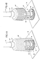
FIGS. 3A to 3C are perspective and partially cutaway views of the connector assembly in different positions according to the first embodiment of the invention; - the
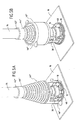
Figures 4A and 4B are views in perspective and partial cutaway of a connector assembly in two different positions according to a second embodiment of the invention; and - the
Figures 5A and 5B perspective and partial cutaway views of a connector assembly in two different positions according to a third embodiment of the invention.
Les
L'ensemble connecteur se compose d'une fiche 10 et d'un socle (ou embase) 12. La fiche 10 est reliée à un câble (ou harnais) électrique 14. Quant au socle 12, il est destiné à être fixé sur une paroi 16 d'un boîtier électrique, par exemple d'un boîtier électrique pour la commande d'un inverseur de poussée utilisé dans le domaine aéronautique.The connector assembly consists of a
La fiche 10 comporte un corps creux 18 de forme sensiblement cylindrique, d'axe longitudinal X-X et à l'intérieur duquel sont montés un ou plusieurs contacts primaires 20. Le socle 12 comporte également un corps creux 22 de forme sensiblement cylindrique, d'axe longitudinal Y-Y et à l'intérieur duquel sont montés un ou plusieurs contacts secondaires 24 aptes à coopérer avec les contacts primaires 20.The
Par coopération entre les contacts primaires 20 et les contacts secondaires 24, on entend une mise en relation permettant d'établir une connexion électrique, c'est-à-dire le passage d'un courant électrique plus ou moins puissant. Ainsi, dans l'exemple de réalisation des
Afin d'éviter toute déconnexion intempestive entre la fiche 10 et le socle 12 de l'ensemble connecteur, la fiche peut également comporter une bague 26 montée coulissante autour du corps cylindrique 18 de la fiche et munie d'un filetage interne, cette bague étant vissée sur un filetage externe 28 complémentaire du corps 22 du socle lorsque la fiche et le socle sont connectés.In order to avoid any inadvertent disconnection between the
Selon l'invention, l'ensemble connecteur comporte en outre un clapet 30 qui est fixé au socle 12. Ce clapet 30 est apte à pivoter entre une position fermée dans laquelle il obstrue un accès aux contacts secondaires 24 (
Plus précisément, le clapet 30 présente une forme de couvercle sensiblement plan de diamètre au moins égal à celui du corps cylindrique 22 du socle 12. Le clapet est monté sur un pivot 32 articulé autour d'un axe 34 parallèle à un plan transversal P du socle (
Selon une caractéristique avantageuse de l'invention, un ressort 36 est enroulé autour du pivot 32 du clapet 30 avec une extrémité fixée au clapet et l'autre extrémité fixée au socle (
Selon une autre caractéristique avantageuse de l'invention, le clapet 30 comporte également un joint silicone 38 sur sa face interne (
Toujours selon l'invention, l'ensemble connecteur comporte également un manchon annulaire 40 fixé au câble électrique 14, relié à la fiche 10 et apte à être déplacé entre deux positions extrêmes, une position basse dans laquelle il recouvre le clapet 30 lorsque la fiche 10 et le socle 12 sont connectés afin de protéger ce dernier contre les polluants (
Dans le premier mode de réalisation de l'invention illustré par les
La cloche 40 est plus particulièrement centrée sur l'axe longitudinal X-X de la fiche 10 et est apte à coulisser le long du câble électrique 14 de façon à passer de l'une de ses positions extrêmes vers l'autre. A cet effet, la cloche 40 est maintenue à l'une des ses extrémités 42 sur le câble électrique 14 au moyen d'un système de fixation amovible. Par exemple, le système de fixation peut être un collier de serrage 44 pouvant être desserré. Quant à l'autre extrémité 46 de la cloche, elle est ouverte et libre.The
Le diamètre de l'extrémité libre 46 de la cloche est plus important que celui de son extrémité 42 maintenue autour du câble de façon à pouvoir recouvrir entièrement le clapet 30 lorsque la fiche et le socle sont connectés. En outre, lorsque la fiche et le socle sont connectés, l'extrémité libre 46 de la cloche peut avantageusement venir en contact avec une bague 48 concentrique au corps 22 du socle, fixée à la paroi 16 et de diamètre légèrement inférieur à l'extrémité libre 46 de la cloche. Une telle bague permet d'éviter tout décentrage intempestif de la cloche par rapport à l'ensemble connecteur.The diameter of the
L'opération de connexion de la fiche 10 sur le socle 12 découle de manière évidente de ce qui précède. La cloche 40 est maintenue fixée sur le câble 14 dans sa position haute dégageant ainsi un accès à la fiche 10. Le clapet 30 est pivoté depuis sa position fermée (
Selon une caractéristique avantageuse de ce premier mode de réalisation représentée sur les
Les
L'ensemble connecteur également un manchon 40' fixé au câble électrique 14 relié à la fiche 10 et apte à être déplacé entre deux positions extrêmes, une position basse dans laquelle il recouvre le clapet 30 lorsque la fiche 10 et le socle 12 sont connectés afin de protéger ce dernier contre les polluants (
Dans ce deuxième mode de réalisation, le manchon 40' présente une structure rétractable de forme sensiblement cylindrique réalisée en un matériau souple ou semi-rigide, tel que par exemple un élastomère.In this second embodiment, the sleeve 40 'has a retractable structure of substantially cylindrical shape made of a flexible or semi-rigid material, such as for example an elastomer.
Cette structure rétractable 40' est centrée sur l'axe longitudinal de la fiche avec une extrémité 42' fixée autour du câble électrique 14 au moyen d'une attache 44', l'autre extrémité 46' étant ouverte et libre. Le diamètre de l'extrémité libre 46' de la structure rétractable 40' est plus important que celui de son extrémité fixe 42' de façon à pouvoir recouvrir entièrement le clapet 30 lorsque la fiche et le socle sont connectés.This retractable structure 40 'is centered on the longitudinal axis of the plug with one end 42' fixed around the
En outre, la structure 40' est apte à se rétracter sur elle-même le long du câble électrique de façon à passer de sa position basse à sa position haute. A cet effet, comme illustré aux
Les
L'ensemble connecteur comporte également un manchon 40" fixé au câble électrique 14 relié à la fiche 10 et apte à être déplacé entre deux positions extrêmes, une position basse dans laquelle il recouvre le clapet 30 lorsque la fiche 10 et le socle 12 sont connectés afin de protéger ce dernier contre les polluants (
Dans ce mode de réalisation, le manchon 40" présente une structure en forme de soufflet sensiblement conique réalisée en un matériau tel que par exemple un élastomère.In this embodiment, the
Cette structure 40" est centrée sur l'axe longitudinal de la fiche avec une extrémité 42" fixée autour du câble électrique 14 au moyen d'une attache 44", l'autre extrémité 46" étant ouverte et libre. Le diamètre de l'extrémité libre 46" du soufflet 40" est plus important que celui de son extrémité fixe 42" de façon à pouvoir recouvrir entièrement le clapet 30 lorsque la fiche et le socle sont connectés.This
De plus, le soufflet 40" est apte à se retrousser sur lui-même le long du câble électrique 14 de façon à passer de sa position basse (
Claims (9)
- Electric connector assembly comprising a plug (10) having primary contacts (20), a base (12) having secondary contacts (24) capable of interacting with the primary contacts, and a closure flap (30) fixed to the base and capable of pivoting between a closed position in which it closes off an access to the secondary contacts (24) and an open position in which it frees an access to the secondary contacts to make it possible to connect the plug to the base; characterized in that it also comprises an annular sleeve (40, 40', 40") fixed to an electric cable (14) connected to the plug (10) and capable of being moved between two extreme positions, a bottom position in which it covers the closure flap (30) when the plug and the base are connected and a top position in which it frees an access to the plug.
- An assembly according to Claim 1, in which:the closure flap (30) is mounted on a pivot (32) with a shaft (34) parallel to a transverse plane (P) of the base (12) so that, in the closed position, the closure flap is substantially parallel to the transverse plane (P) of the base,and in the open position, the closure flap is substantially parallel to a longitudinal plane of the base, anda spring (36) is wound around the pivot (32) in a manner such that the closure flap (30) is kept in its closed position in the absence of force exerted on the latter.
- An assembly according to Claims 1 or 2, in which the closure flap (30) comprises a silicone seal (38) on its inner face so as to provide a sealed obstruction to the secondary contacts (24) of the base (12) when it is in its closed position.
- An assembly according to any one of Claims 1 to 3, in which:the sleeve (40) has a bell-shaped structure centred on a longitudinal axis (X-X) of the plug (10) with a removable fastening system (44) at one of its ends (42) in order to fasten it to the electric cable (14) connected to the plug, the opposite end (46) of the sleeve being open and free, andthe sleeve (40) is capable of sliding along the electric cable (14) so as to pass from one of its extreme positions to the other.
- An assembly according to Claim 4, in which the sleeve (40) comprises at its free end (46) a rigid ring (50).
- An assembly according to any one of Claims 1 to 3, in which:the sleeve (40') has a retractable structure centred on a longitudinal axis (X-X) of the plug (10) with one end (42') attached to the electric cable (14) connected to the plug, the opposite end (46') of the sleeve being open and free, andthe sleeve (40') is capable of retracting on itself along the electric cable (14) so as to pass from its bottom position to its top position.
- An assembly according to any one of Claims 1 to 3, in which:the sleeve (40") has a bellows shape centred on a longitudinal axis (X-X) of the plug (10) with one end (42") attached to the electric cable (14) connected to the plug, the opposite end (46") of the sleeve being open and free, andthe sleeve (40") is capable of folding back on itself along the electric cable (14) so as to pass from its bottom position to its top position.
- Aircraft pod characterized in that it comprises at least one electric connector assembly according to any one of Claims 1 to 7.
- Turbomachine characterized in that it comprises at least one electric connector assembly according to any one of Claims 1 to 7.
Applications Claiming Priority (1)
| Application Number | Priority Date | Filing Date | Title |
|---|---|---|---|
| FR0655627A FR2910184B1 (en) | 2006-12-19 | 2006-12-19 | ELECTRICAL CONNECTOR ASSEMBLY WITH A POLLUTION PROTECTION DEVICE |
Publications (2)
| Publication Number | Publication Date |
|---|---|
| EP1936751A1 EP1936751A1 (en) | 2008-06-25 |
| EP1936751B1 true EP1936751B1 (en) | 2011-10-19 |
Family
ID=38180564
Family Applications (1)
| Application Number | Title | Priority Date | Filing Date |
|---|---|---|---|
| EP07150070A Active EP1936751B1 (en) | 2006-12-19 | 2007-12-17 | Electrical connector assembly equipped with a device for protection against pollution |
Country Status (16)
| Country | Link |
|---|---|
| US (1) | US7758360B2 (en) |
| EP (1) | EP1936751B1 (en) |
| JP (1) | JP5303756B2 (en) |
| CN (1) | CN101237091B (en) |
| AT (1) | ATE529926T1 (en) |
| BR (1) | BRPI0704673A (en) |
| CA (1) | CA2615034C (en) |
| ES (1) | ES2374065T3 (en) |
| FR (1) | FR2910184B1 (en) |
| IL (1) | IL188232A0 (en) |
| MA (1) | MA29902B1 (en) |
| MX (1) | MX2007016432A (en) |
| RU (1) | RU2446527C2 (en) |
| SG (1) | SG144095A1 (en) |
| UA (1) | UA98606C2 (en) |
| ZA (1) | ZA200710970B (en) |
Families Citing this family (19)
| Publication number | Priority date | Publication date | Assignee | Title |
|---|---|---|---|---|
| US8288651B2 (en) * | 2007-09-28 | 2012-10-16 | Kenneth Smith | Weatherproof connector |
| US8853542B2 (en) | 2009-03-30 | 2014-10-07 | John Mezzalingua Associates, LLC | Collar for sealingly engaging a cover for cable connectors |
| US8419467B2 (en) * | 2010-04-14 | 2013-04-16 | John Mezzalingua Associates, Inc. | Cover for cable connectors |
| AU2009201426B2 (en) * | 2009-04-13 | 2013-11-07 | Gravolin, Dennis Ronald Mr | Protective Housing Assembly |
| JP5394152B2 (en) * | 2009-07-17 | 2014-01-22 | 大崎電気工業株式会社 | Protective cover for conductive material |
| DE102009054639A1 (en) * | 2009-12-15 | 2011-06-16 | Robert Bosch Gmbh | Hand tool add-on module |
| US8764480B2 (en) | 2010-04-14 | 2014-07-01 | John Mezzalingua Associates, LLP | Cover for cable connectors |
| JP5732319B2 (en) * | 2011-06-02 | 2015-06-10 | 矢崎総業株式会社 | connector |
| KR20140091604A (en) * | 2011-12-13 | 2014-07-21 | 야자키 소교 가부시키가이샤 | Structute for fixing electrical connection section, connector, and method for connecting connector |
| US8480428B1 (en) * | 2012-01-09 | 2013-07-09 | Devin Sper | Waterproof BNC connector |
| DE102012202225B4 (en) * | 2012-02-14 | 2015-10-22 | Te Connectivity Germany Gmbh | Plug housing with seal |
| JP5931640B2 (en) * | 2012-08-06 | 2016-06-08 | 矢崎総業株式会社 | Spring retaining structure |
| US9597968B2 (en) * | 2013-08-08 | 2017-03-21 | GM Global Technology Operations LLC | Shroud for electric vehicle charger receptacle |
| CN104993289B (en) * | 2015-06-22 | 2018-02-16 | 中航光电科技股份有限公司 | Cable-assembly and the cable disc using the cable-assembly |
| US9796406B2 (en) * | 2015-07-02 | 2017-10-24 | Kubota Corporation | Electric power steering unit with offset link mechanism |
| EP3174160A1 (en) * | 2015-11-30 | 2017-05-31 | GE Energy Power Conversion Technology Ltd | Cover and method for covering a section of at least one conductor |
| US10711506B2 (en) * | 2017-10-13 | 2020-07-14 | Ford Global Technologies, Llc | Charge port assembly with motorized iris door |
| US10886679B1 (en) | 2019-09-27 | 2021-01-05 | Smartplug Systems, LLC | Retrofit electrical system for dockside power pedestals |
| JP2021191177A (en) * | 2020-06-03 | 2021-12-13 | 住友電装株式会社 | Wiring member |
Family Cites Families (20)
| Publication number | Priority date | Publication date | Assignee | Title |
|---|---|---|---|---|
| US3449706A (en) * | 1967-10-12 | 1969-06-10 | Hubbell Inc Harvey | Protective enclosure for electrical wiring devices |
| US4076360A (en) * | 1974-06-21 | 1978-02-28 | The Raymond Lee Organization, Inc. | Safety device for electrical connector device |
| US4245875A (en) * | 1979-06-18 | 1981-01-20 | Amp Incorporated | Heavy duty plug and socket |
| SU1019527A1 (en) * | 1982-02-23 | 1983-05-23 | Blinov Lev S | Electrical plug connector |
| US4702710A (en) * | 1986-06-20 | 1987-10-27 | Georgia Tech Research Corporation | Waterproof seal assembly for electrical connector |
| JPS6379075U (en) * | 1986-11-13 | 1988-05-25 | ||
| US4784610A (en) * | 1987-02-20 | 1988-11-15 | Stuart Clifton F | Electrical connector |
| US5041000A (en) * | 1990-10-12 | 1991-08-20 | Shotey Michael J | Shroud for electrical wall outlets |
| JPH04102171U (en) * | 1991-02-08 | 1992-09-03 | 日本無線株式会社 | Waterproof cap for connector |
| JPH0727346U (en) * | 1993-10-29 | 1995-05-23 | 日本アビオニクス株式会社 | Cover mechanism of the device body leg |
| JP3112226B2 (en) * | 1993-12-27 | 2000-11-27 | 矢崎総業株式会社 | Charging connector for electric vehicles |
| JPH08287998A (en) * | 1995-04-12 | 1996-11-01 | Sony Corp | Output terminal |
| JP3294543B2 (en) * | 1997-11-21 | 2002-06-24 | シャープ株式会社 | Converter for satellite broadcasting reception |
| JP3276142B2 (en) * | 1999-02-02 | 2002-04-22 | 保泉 利夫 | Leakage prevention cover for embedded outlet |
| FR2797097B1 (en) * | 1999-07-26 | 2001-10-05 | Selecom Sud Electronique Comm | SEALING DEVICE FOR SEALING A CONNECTION CONNECTION IN A SIGNAL TRANSMISSION AND / OR RECEPTION LINK |
| US6450833B1 (en) * | 2000-08-25 | 2002-09-17 | Wabash Technology Corporation | Seven-way trailer connector |
| JP4081003B2 (en) * | 2001-07-31 | 2008-04-23 | ライヒレ・ウント・デ−マサリ・アクチエンゲゼルシヤフト | Protection device for plug-in connectors |
| US6851958B1 (en) * | 2002-11-27 | 2005-02-08 | Theodore Bargman Company | Electrical connector assembly |
| CA2540612A1 (en) * | 2005-03-24 | 2006-09-24 | Bld Products, Ltd. | Electrical connector assembly |
| GB0516907D0 (en) * | 2005-08-18 | 2005-09-28 | Earlex Ltd | Connector cover |
-
2006
- 2006-12-19 FR FR0655627A patent/FR2910184B1/en not_active Expired - Fee Related
-
2007
- 2007-12-13 MA MA30481A patent/MA29902B1/en unknown
- 2007-12-14 CA CA2615034A patent/CA2615034C/en active Active
- 2007-12-17 EP EP07150070A patent/EP1936751B1/en active Active
- 2007-12-17 ES ES07150070T patent/ES2374065T3/en active Active
- 2007-12-17 AT AT07150070T patent/ATE529926T1/en not_active IP Right Cessation
- 2007-12-17 SG SG200718816-2A patent/SG144095A1/en unknown
- 2007-12-17 JP JP2007324558A patent/JP5303756B2/en active Active
- 2007-12-18 ZA ZA200710970A patent/ZA200710970B/en unknown
- 2007-12-18 US US11/958,770 patent/US7758360B2/en active Active
- 2007-12-18 BR BRPI0704673-1A patent/BRPI0704673A/en not_active Application Discontinuation
- 2007-12-18 IL IL188232A patent/IL188232A0/en active IP Right Grant
- 2007-12-18 RU RU2007147209/07A patent/RU2446527C2/en active
- 2007-12-18 UA UAA200714228A patent/UA98606C2/en unknown
- 2007-12-19 CN CN2007101610279A patent/CN101237091B/en active Active
- 2007-12-19 MX MX2007016432A patent/MX2007016432A/en active IP Right Grant
Also Published As
| Publication number | Publication date |
|---|---|
| JP5303756B2 (en) | 2013-10-02 |
| UA98606C2 (en) | 2012-06-11 |
| FR2910184B1 (en) | 2009-03-06 |
| ATE529926T1 (en) | 2011-11-15 |
| BRPI0704673A (en) | 2008-08-12 |
| JP2008153225A (en) | 2008-07-03 |
| CA2615034A1 (en) | 2008-06-19 |
| RU2007147209A (en) | 2009-06-27 |
| MA29902B1 (en) | 2008-11-03 |
| US7758360B2 (en) | 2010-07-20 |
| CN101237091B (en) | 2012-06-06 |
| CA2615034C (en) | 2015-07-14 |
| ZA200710970B (en) | 2008-10-29 |
| MX2007016432A (en) | 2009-02-23 |
| IL188232A0 (en) | 2008-11-03 |
| CN101237091A (en) | 2008-08-06 |
| US20080142637A1 (en) | 2008-06-19 |
| RU2446527C2 (en) | 2012-03-27 |
| EP1936751A1 (en) | 2008-06-25 |
| SG144095A1 (en) | 2008-07-29 |
| FR2910184A1 (en) | 2008-06-20 |
| ES2374065T3 (en) | 2012-02-13 |
Similar Documents
| Publication | Publication Date | Title |
|---|---|---|
| EP1936751B1 (en) | Electrical connector assembly equipped with a device for protection against pollution | |
| EP2393165B1 (en) | assembly for electrical connection | |
| EP0854547A1 (en) | Electrical coaxial connecting element with a movable contact and electrical coaxial connector with such a connecting element | |
| FR2619257A1 (en) | ELECTRICAL CONNECTOR ASSEMBLY WITH QUICK DISCONNECT | |
| EP0383661B1 (en) | Device for electrically connecting a cable, in particular one for ignition, with a terminal | |
| FR2923956A1 (en) | LOCKING DEVICE FOR QUICK CONNECT CONNECTION ASSEMBLY AND CONNECTORS EQUIPPED WITH SUCH A DEVICE. | |
| EP0715372B1 (en) | Socket for an electrical connection with protected contacts | |
| EP0112258A2 (en) | Electrical security socket, especially for an explosive atmosphere | |
| WO2015145003A1 (en) | Sealed bushing device for a wiring harness | |
| EP0435707B1 (en) | Ensemble of automatical interconnection, especially for the electrical connection of a modular block containing a plurality of missile launching tubes | |
| FR3045700B1 (en) | ARTICULATED ROTATION DEVICE HAVING AN ELECTRICAL CONNECTION SYSTEM | |
| FR2588414A1 (en) | Three-column insulating electrical switch | |
| FR2873237A1 (en) | Connector assembly for e.g. electronics component, has connection units with permanent protective coverings, and free end of contacts one unit opening in cavity, where each covering has conducting inserts with inner sides opening in cavity | |
| FR3050176B1 (en) | NACELLE FOR PROPULSIVE ASSEMBLY | |
| EP3793894B1 (en) | Fresh-air supply system for a submarine and submarine including such a system | |
| EP0525583A1 (en) | High or very high voltage cable junction assembly | |
| FR2702554A1 (en) | Ammunition, particularly for a large-calibre weapon | |
| FR2705502A1 (en) | Explosion-proof electric connector | |
| FR2774041A1 (en) | Vehicle fuel tank plastics orifice fitting with integral electrical earthing to prevent explosions from static electricity | |
| EP2792593B1 (en) | Improved assembly of a telescopic mast and a device for supporting equipment, for an underwater vehicle | |
| FR3070037A1 (en) | NACELLE FOR PROPULSIVE ASSEMBLY | |
| FR2563662A1 (en) | Electrical connector which can be automatically unplugged | |
| FR2825839A1 (en) | Satellite solar panel/portable computer frictionless electrical connection between elements having moving elements with contact elements and trigger structure disengaging contact surface/switching unit engaging connection position | |
| FR2504720A1 (en) | Self cleaning contact mechanism for artillery shell - has rotating contact completing electrical circuit as cover is removed and breaking circuit when inserted | |
| EP0837530A1 (en) | Electrical connector having a support structure of insulative material |
Legal Events
| Date | Code | Title | Description |
|---|---|---|---|
| PUAI | Public reference made under article 153(3) epc to a published international application that has entered the european phase |
Free format text: ORIGINAL CODE: 0009012 |
|
| 17P | Request for examination filed |
Effective date: 20071217 |
|
| AK | Designated contracting states |
Kind code of ref document: A1 Designated state(s): AT BE BG CH CY CZ DE DK EE ES FI FR GB GR HU IE IS IT LI LT LU LV MC MT NL PL PT RO SE SI SK TR |
|
| AX | Request for extension of the european patent |
Extension state: AL BA HR MK RS |
|
| AKX | Designation fees paid |
Designated state(s): AT BE BG CH CY CZ DE DK EE ES FI FR GB GR HU IE IS IT LI LT LU LV MC MT NL PL PT RO SE SI SK TR |
|
| 17Q | First examination report despatched |
Effective date: 20090420 |
|
| RAP1 | Party data changed (applicant data changed or rights of an application transferred) |
Owner name: SNECMA |
|
| GRAP | Despatch of communication of intention to grant a patent |
Free format text: ORIGINAL CODE: EPIDOSNIGR1 |
|
| GRAS | Grant fee paid |
Free format text: ORIGINAL CODE: EPIDOSNIGR3 |
|
| GRAA | (expected) grant |
Free format text: ORIGINAL CODE: 0009210 |
|
| AK | Designated contracting states |
Kind code of ref document: B1 Designated state(s): AT BE BG CH CY CZ DE DK EE ES FI FR GB GR HU IE IS IT LI LT LU LV MC MT NL PL PT RO SE SI SK TR |
|
| REG | Reference to a national code |
Ref country code: GB Ref legal event code: FG4D Free format text: NOT ENGLISH |
|
| REG | Reference to a national code |
Ref country code: CH Ref legal event code: EP |
|
| REG | Reference to a national code |
Ref country code: IE Ref legal event code: FG4D |
|
| REG | Reference to a national code |
Ref country code: DE Ref legal event code: R096 Ref document number: 602007017991 Country of ref document: DE Effective date: 20111222 |
|
| REG | Reference to a national code |
Ref country code: SE Ref legal event code: TRGR |
|
| REG | Reference to a national code |
Ref country code: NL Ref legal event code: VDEP Effective date: 20111019 |
|
| REG | Reference to a national code |
Ref country code: ES Ref legal event code: FG2A Ref document number: 2374065 Country of ref document: ES Kind code of ref document: T3 Effective date: 20120213 |
|
| LTIE | Lt: invalidation of european patent or patent extension |
Effective date: 20111019 |
|
| REG | Reference to a national code |
Ref country code: AT Ref legal event code: MK05 Ref document number: 529926 Country of ref document: AT Kind code of ref document: T Effective date: 20111019 |
|
| PG25 | Lapsed in a contracting state [announced via postgrant information from national office to epo] |
Ref country code: IS Free format text: LAPSE BECAUSE OF FAILURE TO SUBMIT A TRANSLATION OF THE DESCRIPTION OR TO PAY THE FEE WITHIN THE PRESCRIBED TIME-LIMIT Effective date: 20120219 Ref country code: LT Free format text: LAPSE BECAUSE OF FAILURE TO SUBMIT A TRANSLATION OF THE DESCRIPTION OR TO PAY THE FEE WITHIN THE PRESCRIBED TIME-LIMIT Effective date: 20111019 |
|
| REG | Reference to a national code |
Ref country code: IE Ref legal event code: FD4D |
|
| PG25 | Lapsed in a contracting state [announced via postgrant information from national office to epo] |
Ref country code: NL Free format text: LAPSE BECAUSE OF FAILURE TO SUBMIT A TRANSLATION OF THE DESCRIPTION OR TO PAY THE FEE WITHIN THE PRESCRIBED TIME-LIMIT Effective date: 20111019 Ref country code: GR Free format text: LAPSE BECAUSE OF FAILURE TO SUBMIT A TRANSLATION OF THE DESCRIPTION OR TO PAY THE FEE WITHIN THE PRESCRIBED TIME-LIMIT Effective date: 20120120 Ref country code: PT Free format text: LAPSE BECAUSE OF FAILURE TO SUBMIT A TRANSLATION OF THE DESCRIPTION OR TO PAY THE FEE WITHIN THE PRESCRIBED TIME-LIMIT Effective date: 20120220 Ref country code: LV Free format text: LAPSE BECAUSE OF FAILURE TO SUBMIT A TRANSLATION OF THE DESCRIPTION OR TO PAY THE FEE WITHIN THE PRESCRIBED TIME-LIMIT Effective date: 20111019 Ref country code: SI Free format text: LAPSE BECAUSE OF FAILURE TO SUBMIT A TRANSLATION OF THE DESCRIPTION OR TO PAY THE FEE WITHIN THE PRESCRIBED TIME-LIMIT Effective date: 20111019 |
|
| PG25 | Lapsed in a contracting state [announced via postgrant information from national office to epo] |
Ref country code: CY Free format text: LAPSE BECAUSE OF FAILURE TO SUBMIT A TRANSLATION OF THE DESCRIPTION OR TO PAY THE FEE WITHIN THE PRESCRIBED TIME-LIMIT Effective date: 20111019 |
|
| BERE | Be: lapsed |
Owner name: SNECMA Effective date: 20111231 |
|
| PG25 | Lapsed in a contracting state [announced via postgrant information from national office to epo] |
Ref country code: CZ Free format text: LAPSE BECAUSE OF FAILURE TO SUBMIT A TRANSLATION OF THE DESCRIPTION OR TO PAY THE FEE WITHIN THE PRESCRIBED TIME-LIMIT Effective date: 20111019 Ref country code: DK Free format text: LAPSE BECAUSE OF FAILURE TO SUBMIT A TRANSLATION OF THE DESCRIPTION OR TO PAY THE FEE WITHIN THE PRESCRIBED TIME-LIMIT Effective date: 20111019 Ref country code: BG Free format text: LAPSE BECAUSE OF FAILURE TO SUBMIT A TRANSLATION OF THE DESCRIPTION OR TO PAY THE FEE WITHIN THE PRESCRIBED TIME-LIMIT Effective date: 20120119 Ref country code: SK Free format text: LAPSE BECAUSE OF FAILURE TO SUBMIT A TRANSLATION OF THE DESCRIPTION OR TO PAY THE FEE WITHIN THE PRESCRIBED TIME-LIMIT Effective date: 20111019 Ref country code: IE Free format text: LAPSE BECAUSE OF FAILURE TO SUBMIT A TRANSLATION OF THE DESCRIPTION OR TO PAY THE FEE WITHIN THE PRESCRIBED TIME-LIMIT Effective date: 20111019 Ref country code: EE Free format text: LAPSE BECAUSE OF FAILURE TO SUBMIT A TRANSLATION OF THE DESCRIPTION OR TO PAY THE FEE WITHIN THE PRESCRIBED TIME-LIMIT Effective date: 20111019 Ref country code: MC Free format text: LAPSE BECAUSE OF NON-PAYMENT OF DUE FEES Effective date: 20111231 |
|
| REG | Reference to a national code |
Ref country code: CH Ref legal event code: PL |
|
| PLBE | No opposition filed within time limit |
Free format text: ORIGINAL CODE: 0009261 |
|
| STAA | Information on the status of an ep patent application or granted ep patent |
Free format text: STATUS: NO OPPOSITION FILED WITHIN TIME LIMIT |
|
| PG25 | Lapsed in a contracting state [announced via postgrant information from national office to epo] |
Ref country code: RO Free format text: LAPSE BECAUSE OF FAILURE TO SUBMIT A TRANSLATION OF THE DESCRIPTION OR TO PAY THE FEE WITHIN THE PRESCRIBED TIME-LIMIT Effective date: 20111019 Ref country code: PL Free format text: LAPSE BECAUSE OF FAILURE TO SUBMIT A TRANSLATION OF THE DESCRIPTION OR TO PAY THE FEE WITHIN THE PRESCRIBED TIME-LIMIT Effective date: 20111019 |
|
| 26N | No opposition filed |
Effective date: 20120720 |
|
| PG25 | Lapsed in a contracting state [announced via postgrant information from national office to epo] |
Ref country code: BE Free format text: LAPSE BECAUSE OF NON-PAYMENT OF DUE FEES Effective date: 20111231 Ref country code: LI Free format text: LAPSE BECAUSE OF NON-PAYMENT OF DUE FEES Effective date: 20111231 Ref country code: CH Free format text: LAPSE BECAUSE OF NON-PAYMENT OF DUE FEES Effective date: 20111231 |
|
| REG | Reference to a national code |
Ref country code: DE Ref legal event code: R097 Ref document number: 602007017991 Country of ref document: DE Effective date: 20120720 |
|
| PG25 | Lapsed in a contracting state [announced via postgrant information from national office to epo] |
Ref country code: AT Free format text: LAPSE BECAUSE OF FAILURE TO SUBMIT A TRANSLATION OF THE DESCRIPTION OR TO PAY THE FEE WITHIN THE PRESCRIBED TIME-LIMIT Effective date: 20111019 |
|
| PG25 | Lapsed in a contracting state [announced via postgrant information from national office to epo] |
Ref country code: MT Free format text: LAPSE BECAUSE OF FAILURE TO SUBMIT A TRANSLATION OF THE DESCRIPTION OR TO PAY THE FEE WITHIN THE PRESCRIBED TIME-LIMIT Effective date: 20111019 |
|
| PGFP | Annual fee paid to national office [announced via postgrant information from national office to epo] |
Ref country code: ES Payment date: 20121205 Year of fee payment: 6 |
|
| PG25 | Lapsed in a contracting state [announced via postgrant information from national office to epo] |
Ref country code: LU Free format text: LAPSE BECAUSE OF NON-PAYMENT OF DUE FEES Effective date: 20111217 |
|
| PG25 | Lapsed in a contracting state [announced via postgrant information from national office to epo] |
Ref country code: FI Free format text: LAPSE BECAUSE OF FAILURE TO SUBMIT A TRANSLATION OF THE DESCRIPTION OR TO PAY THE FEE WITHIN THE PRESCRIBED TIME-LIMIT Effective date: 20111019 |
|
| PG25 | Lapsed in a contracting state [announced via postgrant information from national office to epo] |
Ref country code: TR Free format text: LAPSE BECAUSE OF FAILURE TO SUBMIT A TRANSLATION OF THE DESCRIPTION OR TO PAY THE FEE WITHIN THE PRESCRIBED TIME-LIMIT Effective date: 20111019 |
|
| PG25 | Lapsed in a contracting state [announced via postgrant information from national office to epo] |
Ref country code: HU Free format text: LAPSE BECAUSE OF FAILURE TO SUBMIT A TRANSLATION OF THE DESCRIPTION OR TO PAY THE FEE WITHIN THE PRESCRIBED TIME-LIMIT Effective date: 20111019 |
|
| REG | Reference to a national code |
Ref country code: ES Ref legal event code: FD2A Effective date: 20150701 |
|
| PG25 | Lapsed in a contracting state [announced via postgrant information from national office to epo] |
Ref country code: ES Free format text: LAPSE BECAUSE OF NON-PAYMENT OF DUE FEES Effective date: 20131218 |
|
| REG | Reference to a national code |
Ref country code: FR Ref legal event code: PLFP Year of fee payment: 9 |
|
| REG | Reference to a national code |
Ref country code: FR Ref legal event code: PLFP Year of fee payment: 10 |
|
| REG | Reference to a national code |
Ref country code: FR Ref legal event code: PLFP Year of fee payment: 11 |
|
| REG | Reference to a national code |
Ref country code: FR Ref legal event code: CD Owner name: SAFRAN AIRCRAFT ENGINES, FR Effective date: 20170717 |
|
| PGFP | Annual fee paid to national office [announced via postgrant information from national office to epo] |
Ref country code: IT Payment date: 20221122 Year of fee payment: 16 |
|
| PGFP | Annual fee paid to national office [announced via postgrant information from national office to epo] |
Ref country code: GB Payment date: 20231121 Year of fee payment: 17 |
|
| PGFP | Annual fee paid to national office [announced via postgrant information from national office to epo] |
Ref country code: SE Payment date: 20231121 Year of fee payment: 17 Ref country code: FR Payment date: 20231122 Year of fee payment: 17 Ref country code: DE Payment date: 20231121 Year of fee payment: 17 |