EP1936315A1 - Protected carbon steel pipe for conveying flue gases in a heat exchange apparatus - Google Patents
Protected carbon steel pipe for conveying flue gases in a heat exchange apparatus Download PDFInfo
- Publication number
- EP1936315A1 EP1936315A1 EP07023047A EP07023047A EP1936315A1 EP 1936315 A1 EP1936315 A1 EP 1936315A1 EP 07023047 A EP07023047 A EP 07023047A EP 07023047 A EP07023047 A EP 07023047A EP 1936315 A1 EP1936315 A1 EP 1936315A1
- Authority
- EP
- European Patent Office
- Prior art keywords
- carbon steel
- flue gases
- heat exchange
- steel pipe
- exchange apparatus
- Prior art date
- Legal status (The legal status is an assumption and is not a legal conclusion. Google has not performed a legal analysis and makes no representation as to the accuracy of the status listed.)
- Withdrawn
Links
- 229910000975 Carbon steel Inorganic materials 0.000 title claims abstract description 17
- 239000010962 carbon steel Substances 0.000 title claims abstract description 17
- 239000003546 flue gas Substances 0.000 title claims abstract description 14
- 230000007797 corrosion Effects 0.000 claims abstract description 12
- 238000005260 corrosion Methods 0.000 claims abstract description 12
- 239000000463 material Substances 0.000 claims abstract description 11
- UGFAIRIUMAVXCW-UHFFFAOYSA-N Carbon monoxide Chemical compound [O+]#[C-] UGFAIRIUMAVXCW-UHFFFAOYSA-N 0.000 description 3
- 238000009833 condensation Methods 0.000 description 2
- 230000005494 condensation Effects 0.000 description 2
- 230000008595 infiltration Effects 0.000 description 2
- 238000001764 infiltration Methods 0.000 description 2
- 230000000670 limiting effect Effects 0.000 description 2
- XLYOFNOQVPJJNP-UHFFFAOYSA-N water Substances O XLYOFNOQVPJJNP-UHFFFAOYSA-N 0.000 description 2
- 229910000838 Al alloy Inorganic materials 0.000 description 1
- 238000002485 combustion reaction Methods 0.000 description 1
- 239000012530 fluid Substances 0.000 description 1
- 239000013529 heat transfer fluid Substances 0.000 description 1
- 238000012986 modification Methods 0.000 description 1
- 230000004048 modification Effects 0.000 description 1
- 239000010935 stainless steel Substances 0.000 description 1
- 229910001220 stainless steel Inorganic materials 0.000 description 1
Images

Classifications
-
- F—MECHANICAL ENGINEERING; LIGHTING; HEATING; WEAPONS; BLASTING
- F28—HEAT EXCHANGE IN GENERAL
- F28F—DETAILS OF HEAT-EXCHANGE AND HEAT-TRANSFER APPARATUS, OF GENERAL APPLICATION
- F28F1/00—Tubular elements; Assemblies of tubular elements
- F28F1/10—Tubular elements and assemblies thereof with means for increasing heat-transfer area, e.g. with fins, with projections, with recesses
- F28F1/40—Tubular elements and assemblies thereof with means for increasing heat-transfer area, e.g. with fins, with projections, with recesses the means being only inside the tubular element
-
- F—MECHANICAL ENGINEERING; LIGHTING; HEATING; WEAPONS; BLASTING
- F28—HEAT EXCHANGE IN GENERAL
- F28F—DETAILS OF HEAT-EXCHANGE AND HEAT-TRANSFER APPARATUS, OF GENERAL APPLICATION
- F28F19/00—Preventing the formation of deposits or corrosion, e.g. by using filters or scrapers
- F28F19/02—Preventing the formation of deposits or corrosion, e.g. by using filters or scrapers by using coatings, e.g. vitreous or enamel coatings
-
- F—MECHANICAL ENGINEERING; LIGHTING; HEATING; WEAPONS; BLASTING
- F28—HEAT EXCHANGE IN GENERAL
- F28F—DETAILS OF HEAT-EXCHANGE AND HEAT-TRANSFER APPARATUS, OF GENERAL APPLICATION
- F28F21/00—Constructions of heat-exchange apparatus characterised by the selection of particular materials
- F28F21/08—Constructions of heat-exchange apparatus characterised by the selection of particular materials of metal
- F28F21/081—Heat exchange elements made from metals or metal alloys
- F28F21/082—Heat exchange elements made from metals or metal alloys from steel or ferrous alloys
Definitions
- the invention relates to a protected carbon steel pipe for conveying flue gases in a heat exchange apparatus.
- heat exchange apparatuses such as for example fire tube boilers for generating hot water or another heat transfer fluid
- different apparatuses of industrial thermal cycles such as for example condensers, economizers, heat exchangers, which provide for the presence of pipes designed to convey flue gases produced by combustion in appropriately provided furnaces, inserted within a vessel which contains the fluid to be heated.
- the pipes comprised within such apparatuses are made of carbon steel in order to ensure optimum quality of the welded joints between the pipes and the structures of the apparatuses, which are also made of carbon steel, and in the case of apparatuses such as for example condensing boilers, in which the water vapor contained in the flue gases condenses inside the flue gas conveyance pipes, forming corrosive condensation, the internal surface of the pipes is protected in different manners.
- pipes have been proposed which comprise an outer jacket which is made of carbon steel and is provided internally with a plurality of contiguous sectors which are made of corrosion-resistant material and are provided with variously shaped fins, but in this embodiment flue gases can penetrate between one sector and the other, with the consequent possibility of contact of such flue gas, which has cooled and therefore carries corrosive condensation, with the outer jacket, which accordingly is not protected fully.
- the aim of the present invention is to provide a protected carbon steel pipe which comprises the elements described above and in which full protection of the outer jacket made of carbon steel is ensured.
- a protected carbon steel pipe for conveying flue gases in a heat exchange apparatus comprising an outer jacket made of carbon steel, which is provided internally with a plurality of contiguous sectors made of corrosion-resistant material and provided with variously shaped fins, characterized by the presence of a continuous layer made of corrosion-resistant material which is interposed and in contact between said outer jacket and said plurality of contiguous sectors.
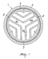
- the reference numeral 1 generally designates a pipe according to the invention, which comprises an outer jacket 2 made of carbon steel and provided internally with contiguous sectors 3, 4, 5 made of corrosion-resistant material, such as for example aluminum alloy or stainless steel, and which are provided with fins 3a, 4a, 5a respectively for the sectors 3, 4, 5.
- An important feature of the invention is the presence of a continuous layer 6 made of corrosion-resistant material, which is interposed between the outer jacket 2 and the sectors 3, 4, 5 and adheres both to the jacket and to the sectors.
- the outer jacket 2 made of carbon steel has a complete protection against corrosion, because any infiltrations of flue gases between one sector and the other are blocked by the layer 6 and any contact between the flue gases and the jacket is thus prevented.
- FIG. 2 illustrates a pipe 7 in which the outer jacket 8 made of carbon steel is provided internally with a plurality of sectors 9 which are made of corrosion-resistant material and are provided with fins 9a, 9b, which are shaped so as to define a plurality of flue gas conveyance modules which are substantially shaped like sectors.
- the reference numeral 10 designates the continuous layer made of corrosion-resistant material which, interposed so as to adhere between the outer jacket 8 and the plurality of sectors 9, provides full protection of the jacket against any infiltrations of flue gases which may occur between one sector and another.
Landscapes
- Engineering & Computer Science (AREA)
- Physics & Mathematics (AREA)
- Thermal Sciences (AREA)
- Mechanical Engineering (AREA)
- General Engineering & Computer Science (AREA)
- Geometry (AREA)
- Heat-Exchange Devices With Radiators And Conduit Assemblies (AREA)
- Rigid Pipes And Flexible Pipes (AREA)
Abstract
Description
- The invention relates to a protected carbon steel pipe for conveying flue gases in a heat exchange apparatus.
- It is known that there are heat exchange apparatuses, such as for example fire tube boilers for generating hot water or another heat transfer fluid, or different apparatuses of industrial thermal cycles, such as for example condensers, economizers, heat exchangers, which provide for the presence of pipes designed to convey flue gases produced by combustion in appropriately provided furnaces, inserted within a vessel which contains the fluid to be heated.
- The pipes comprised within such apparatuses are made of carbon steel in order to ensure optimum quality of the welded joints between the pipes and the structures of the apparatuses, which are also made of carbon steel, and in the case of apparatuses such as for example condensing boilers, in which the water vapor contained in the flue gases condenses inside the flue gas conveyance pipes, forming corrosive condensation, the internal surface of the pipes is protected in different manners.
- For example, pipes have been proposed which comprise an outer jacket which is made of carbon steel and is provided internally with a plurality of contiguous sectors which are made of corrosion-resistant material and are provided with variously shaped fins, but in this embodiment flue gases can penetrate between one sector and the other, with the consequent possibility of contact of such flue gas, which has cooled and therefore carries corrosive condensation, with the outer jacket, which accordingly is not protected fully.
- The aim of the present invention is to provide a protected carbon steel pipe which comprises the elements described above and in which full protection of the outer jacket made of carbon steel is ensured.
- The proposed aim is achieved by a protected carbon steel pipe for conveying flue gases in a heat exchange apparatus, according to the invention, comprising an outer jacket made of carbon steel, which is provided internally with a plurality of contiguous sectors made of corrosion-resistant material and provided with variously shaped fins, characterized by the presence of a continuous layer made of corrosion-resistant material which is interposed and in contact between said outer jacket and said plurality of contiguous sectors.
- Further characteristics and advantages of the present invention will become better apparent from the description of two preferred but not exclusive embodiments of the invention, illustrated by way of non-limiting example in the accompanying drawings, wherein:
-
Figure 1 is a transverse sectional view of the protected carbon steel pipe according to the invention; -
Figure 2 is a transverse sectional view according to a different embodiment. - With reference to
Figure 1 , the reference numeral 1 generally designates a pipe according to the invention, which comprises anouter jacket 2 made of carbon steel and provided internally withcontiguous sectors fins 3a, 4a, 5a respectively for thesectors - An important feature of the invention is the presence of a
continuous layer 6 made of corrosion-resistant material, which is interposed between theouter jacket 2 and thesectors - In this manner, the
outer jacket 2 made of carbon steel has a complete protection against corrosion, because any infiltrations of flue gases between one sector and the other are blocked by thelayer 6 and any contact between the flue gases and the jacket is thus prevented. - The embodiment of
Figure 2 illustrates a pipe 7 in which the outer jacket 8 made of carbon steel is provided internally with a plurality ofsectors 9 which are made of corrosion-resistant material and are provided withfins 9a, 9b, which are shaped so as to define a plurality of flue gas conveyance modules which are substantially shaped like sectors. - In the second embodiment, the
reference numeral 10 designates the continuous layer made of corrosion-resistant material which, interposed so as to adhere between the outer jacket 8 and the plurality ofsectors 9, provides full protection of the jacket against any infiltrations of flue gases which may occur between one sector and another. - The described invention is susceptible of numerous modifications and variations, all of which are within the scope of the appended claims; all the details may further be replaced with other technically equivalent elements.
- The disclosures in
Italian Patent Application No. MN2006A000071 - Where technical features mentioned in any claim are followed by reference signs, those reference signs have been included for the sole purpose of increasing the intelligibility of the claims and accordingly, such reference signs do not have any limiting effect on the interpretation of each element identified by way of example by such reference signs.
Claims (1)
- A protected carbon steel pipe (1; 7) for conveying flue gases in a heat exchange apparatus, comprising an outer jacket (2; 8) made of carbon steel, which is provided internally with a plurality of contiguous sectors (3, 4, 5; 9) made of corrosion-resistant material and provided with variously shaped fins (3a, 4a, 5a; 9a), characterized by the presence of a continuous layer (6; 10) made of corrosion-resistant material which is interposed and in contact between the outer jacket (2; 8) and said plurality of contiguous sectors (3, 4, 5; 9).
Applications Claiming Priority (1)
| Application Number | Priority Date | Filing Date | Title |
|---|---|---|---|
| IT000071A ITMN20060071A1 (en) | 2006-12-13 | 2006-12-13 | CARBON STEEL PIPE PROTECTED FOR THE CONVEYANCE OF FUMES IN HEAT EXCHANGE APPLIANCE. |
Publications (1)
| Publication Number | Publication Date |
|---|---|
| EP1936315A1 true EP1936315A1 (en) | 2008-06-25 |
Family
ID=39111884
Family Applications (1)
| Application Number | Title | Priority Date | Filing Date |
|---|---|---|---|
| EP07023047A Withdrawn EP1936315A1 (en) | 2006-12-13 | 2007-11-28 | Protected carbon steel pipe for conveying flue gases in a heat exchange apparatus |
Country Status (4)
| Country | Link |
|---|---|
| US (1) | US20080142205A1 (en) |
| EP (1) | EP1936315A1 (en) |
| CA (1) | CA2613575A1 (en) |
| IT (1) | ITMN20060071A1 (en) |
Cited By (3)
| Publication number | Priority date | Publication date | Assignee | Title |
|---|---|---|---|---|
| WO2010129847A3 (en) * | 2009-05-08 | 2011-11-10 | E. I. Du Pont De Nemours And Company | Process of using an improved flue in a titanium dioxide process |
| ITMI20101086A1 (en) * | 2010-06-16 | 2011-12-17 | Unical Ag Spa | TUBE IN BOILER WITH SMOKE PIPES. |
| EP2944910A1 (en) * | 2014-05-13 | 2015-11-18 | Grand Hall Enterprise Co., Ltd. | Heat exchanger tube |
Families Citing this family (2)
| Publication number | Priority date | Publication date | Assignee | Title |
|---|---|---|---|---|
| CN105757643B (en) * | 2016-04-11 | 2019-12-17 | 深圳市龙瑞泰兴能源环境科技有限公司 | A boiler using enhanced heat transfer parts |
| US20180202724A1 (en) * | 2017-01-19 | 2018-07-19 | Dong Yong Hot Water System Inc. | Conductive structure of heat exchange pipe |
Citations (3)
| Publication number | Priority date | Publication date | Assignee | Title |
|---|---|---|---|---|
| WO1992020975A1 (en) * | 1991-05-22 | 1992-11-26 | Philipp Kreis Gmbh & Co. Truma-Gerätebau | Air heater |
| EP1617139A1 (en) * | 2004-07-13 | 2006-01-18 | UNICAL AG S.p.A. | Pipe in a fire tube boiler |
| WO2006111315A1 (en) | 2005-04-18 | 2006-10-26 | Unical Ag S.P.A. | Protected carbon steel pipe for fire tube heat exchange devices, particularly boilers |
Family Cites Families (1)
| Publication number | Priority date | Publication date | Assignee | Title |
|---|---|---|---|---|
| DE9405062U1 (en) * | 1994-03-24 | 1994-05-26 | Hoval Interliz Ag, Vaduz-Neugut | Heat exchanger tube for boilers |
-
2006
- 2006-12-13 IT IT000071A patent/ITMN20060071A1/en unknown
-
2007
- 2007-11-28 EP EP07023047A patent/EP1936315A1/en not_active Withdrawn
- 2007-11-30 US US11/987,436 patent/US20080142205A1/en not_active Abandoned
- 2007-12-04 CA CA002613575A patent/CA2613575A1/en not_active Abandoned
Patent Citations (3)
| Publication number | Priority date | Publication date | Assignee | Title |
|---|---|---|---|---|
| WO1992020975A1 (en) * | 1991-05-22 | 1992-11-26 | Philipp Kreis Gmbh & Co. Truma-Gerätebau | Air heater |
| EP1617139A1 (en) * | 2004-07-13 | 2006-01-18 | UNICAL AG S.p.A. | Pipe in a fire tube boiler |
| WO2006111315A1 (en) | 2005-04-18 | 2006-10-26 | Unical Ag S.P.A. | Protected carbon steel pipe for fire tube heat exchange devices, particularly boilers |
Cited By (5)
| Publication number | Priority date | Publication date | Assignee | Title |
|---|---|---|---|---|
| WO2010129847A3 (en) * | 2009-05-08 | 2011-11-10 | E. I. Du Pont De Nemours And Company | Process of using an improved flue in a titanium dioxide process |
| CN102422115A (en) * | 2009-05-08 | 2012-04-18 | 纳幕尔杜邦公司 | Method for using improved flue in titania process |
| ITMI20101086A1 (en) * | 2010-06-16 | 2011-12-17 | Unical Ag Spa | TUBE IN BOILER WITH SMOKE PIPES. |
| WO2011157495A1 (en) * | 2010-06-16 | 2011-12-22 | Unical Ag S.P.A | Tube in fire tube boiler |
| EP2944910A1 (en) * | 2014-05-13 | 2015-11-18 | Grand Hall Enterprise Co., Ltd. | Heat exchanger tube |
Also Published As
| Publication number | Publication date |
|---|---|
| CA2613575A1 (en) | 2008-06-13 |
| US20080142205A1 (en) | 2008-06-19 |
| ITMN20060071A1 (en) | 2008-06-14 |
Similar Documents
| Publication | Publication Date | Title |
|---|---|---|
| CN100535500C (en) | Flow through tube plug | |
| US20080314378A1 (en) | Heat exchanger | |
| US20080142205A1 (en) | Protected carbon steel pipe for conveying flue gases in a heat exchange apparatus | |
| EP2482020A2 (en) | Heat exchanger | |
| CN101631998A (en) | Heat exchange tube and method for manufacturing heat exchange tube | |
| CN112229242A (en) | Heat exchanger for quenching reaction gas | |
| EP1617139B1 (en) | Pipe in a fire tube boiler | |
| CN113487120B (en) | Method for establishing boiler flue anti-corrosion strategy and boiler flue anti-corrosion method | |
| MX2010006119A (en) | Firetube heat exchanger. | |
| US20090266529A1 (en) | Protected Carbon Steel Pipe for Fire Tube Heat Exchange Devices, Particularly Boilers | |
| JP2009257608A (en) | Fin tube, heat exchanger, and manufacturing method of fin tube | |
| JP2018162917A (en) | Method for operating gas preheating device | |
| JP2005061712A (en) | Latent heat recovering economizer with enhanced corrosion resistance | |
| JP4754959B2 (en) | Heat exchanger | |
| JP4615422B2 (en) | Heat transfer tubes, heat exchangers for hot water supply and heat pump water heaters | |
| US11859911B2 (en) | Coaxial heat transfer tube suitable for a fluidized bed boiler and a method for manufacturing same | |
| JP2007163115A (en) | Heat exchanger | |
| TWI554728B (en) | Alloy coated boiler component | |
| US11371694B2 (en) | Fire tube | |
| EP2409105A1 (en) | Tube for conveying exhaust gases in heat exchange devices, particularly boilers for generating hot water or steam | |
| CN104121801A (en) | Welding spot protecting structure of condensation heat exchanger | |
| JP2003254626A (en) | Heat exchange equipment | |
| JP2012037124A (en) | Heat exchanger for corrosive high-temperature gas | |
| KR20110082351A (en) | Heat transfer tube made of release material | |
| JP2001004228A (en) | Latent heat recovery heat exchanger |
Legal Events
| Date | Code | Title | Description |
|---|---|---|---|
| PUAI | Public reference made under article 153(3) epc to a published international application that has entered the european phase |
Free format text: ORIGINAL CODE: 0009012 |
|
| AK | Designated contracting states |
Kind code of ref document: A1 Designated state(s): AT BE BG CH CY CZ DE DK EE ES FI FR GB GR HU IE IS IT LI LT LU LV MC MT NL PL PT RO SE SI SK TR |
|
| AX | Request for extension of the european patent |
Extension state: AL BA HR MK RS |
|
| 17P | Request for examination filed |
Effective date: 20081224 |
|
| AKX | Designation fees paid |
Designated state(s): AT BE BG CH CY CZ DE DK EE ES FI FR GB GR HU IE IS IT LI LT LU LV MC MT NL PL PT RO SE SI SK TR |
|
| 17Q | First examination report despatched |
Effective date: 20090220 |
|
| STAA | Information on the status of an ep patent application or granted ep patent |
Free format text: STATUS: THE APPLICATION IS DEEMED TO BE WITHDRAWN |
|
| 18D | Application deemed to be withdrawn |
Effective date: 20090703 |