EP1936238B1 - Couplage magnétique variable de machinerie rotative - Google Patents
Couplage magnétique variable de machinerie rotative Download PDFInfo
- Publication number
- EP1936238B1 EP1936238B1 EP07123135.1A EP07123135A EP1936238B1 EP 1936238 B1 EP1936238 B1 EP 1936238B1 EP 07123135 A EP07123135 A EP 07123135A EP 1936238 B1 EP1936238 B1 EP 1936238B1
- Authority
- EP
- European Patent Office
- Prior art keywords
- ring structure
- engine
- torque
- magnetic
- spool
- Prior art date
- Legal status (The legal status is an assumption and is not a legal conclusion. Google has not performed a legal analysis and makes no representation as to the accuracy of the status listed.)
- Not-in-force
Links
- 230000005291 magnetic effect Effects 0.000 title claims description 74
- 238000010168 coupling process Methods 0.000 title description 23
- 238000005859 coupling reaction Methods 0.000 title description 21
- 230000008878 coupling Effects 0.000 title description 20
- 230000004044 response Effects 0.000 claims description 3
- 230000006698 induction Effects 0.000 claims description 2
- 230000005672 electromagnetic field Effects 0.000 claims 1
- 239000007789 gas Substances 0.000 description 8
- 230000008901 benefit Effects 0.000 description 7
- 238000000034 method Methods 0.000 description 7
- 239000000567 combustion gas Substances 0.000 description 5
- 230000005540 biological transmission Effects 0.000 description 4
- 239000000446 fuel Substances 0.000 description 4
- 239000007858 starting material Substances 0.000 description 4
- 239000000969 carrier Substances 0.000 description 3
- 239000000284 extract Substances 0.000 description 3
- 230000001965 increasing effect Effects 0.000 description 3
- 230000001133 acceleration Effects 0.000 description 2
- 238000006243 chemical reaction Methods 0.000 description 2
- 230000001419 dependent effect Effects 0.000 description 2
- 238000006073 displacement reaction Methods 0.000 description 2
- 238000000605 extraction Methods 0.000 description 2
- 239000000463 material Substances 0.000 description 2
- 230000009466 transformation Effects 0.000 description 2
- 230000009286 beneficial effect Effects 0.000 description 1
- 230000008859 change Effects 0.000 description 1
- 238000002485 combustion reaction Methods 0.000 description 1
- 238000004891 communication Methods 0.000 description 1
- 230000006835 compression Effects 0.000 description 1
- 238000007906 compression Methods 0.000 description 1
- 230000003247 decreasing effect Effects 0.000 description 1
- 238000010586 diagram Methods 0.000 description 1
- 238000009826 distribution Methods 0.000 description 1
- 230000002708 enhancing effect Effects 0.000 description 1
- 238000004519 manufacturing process Methods 0.000 description 1
- 230000009347 mechanical transmission Effects 0.000 description 1
- 230000007246 mechanism Effects 0.000 description 1
- 239000000203 mixture Substances 0.000 description 1
- 238000005457 optimization Methods 0.000 description 1
- 238000010079 rubber tapping Methods 0.000 description 1
- 238000009987 spinning Methods 0.000 description 1
Images


Classifications
-
- H—ELECTRICITY
- H02—GENERATION; CONVERSION OR DISTRIBUTION OF ELECTRIC POWER
- H02K—DYNAMO-ELECTRIC MACHINES
- H02K49/00—Dynamo-electric clutches; Dynamo-electric brakes
- H02K49/10—Dynamo-electric clutches; Dynamo-electric brakes of the permanent-magnet type
- H02K49/102—Magnetic gearings, i.e. assembly of gears, linear or rotary, by which motion is magnetically transferred without physical contact
-
- F—MECHANICAL ENGINEERING; LIGHTING; HEATING; WEAPONS; BLASTING
- F01—MACHINES OR ENGINES IN GENERAL; ENGINE PLANTS IN GENERAL; STEAM ENGINES
- F01D—NON-POSITIVE DISPLACEMENT MACHINES OR ENGINES, e.g. STEAM TURBINES
- F01D15/00—Adaptations of machines or engines for special use; Combinations of engines with devices driven thereby
- F01D15/10—Adaptations for driving, or combinations with, electric generators
-
- F—MECHANICAL ENGINEERING; LIGHTING; HEATING; WEAPONS; BLASTING
- F02—COMBUSTION ENGINES; HOT-GAS OR COMBUSTION-PRODUCT ENGINE PLANTS
- F02C—GAS-TURBINE PLANTS; AIR INTAKES FOR JET-PROPULSION PLANTS; CONTROLLING FUEL SUPPLY IN AIR-BREATHING JET-PROPULSION PLANTS
- F02C3/00—Gas-turbine plants characterised by the use of combustion products as the working fluid
- F02C3/04—Gas-turbine plants characterised by the use of combustion products as the working fluid having a turbine driving a compressor
- F02C3/107—Gas-turbine plants characterised by the use of combustion products as the working fluid having a turbine driving a compressor with two or more rotors connected by power transmission
- F02C3/113—Gas-turbine plants characterised by the use of combustion products as the working fluid having a turbine driving a compressor with two or more rotors connected by power transmission with variable power transmission between rotors
-
- F—MECHANICAL ENGINEERING; LIGHTING; HEATING; WEAPONS; BLASTING
- F02—COMBUSTION ENGINES; HOT-GAS OR COMBUSTION-PRODUCT ENGINE PLANTS
- F02C—GAS-TURBINE PLANTS; AIR INTAKES FOR JET-PROPULSION PLANTS; CONTROLLING FUEL SUPPLY IN AIR-BREATHING JET-PROPULSION PLANTS
- F02C7/00—Features, components parts, details or accessories, not provided for in, or of interest apart form groups F02C1/00 - F02C6/00; Air intakes for jet-propulsion plants
- F02C7/32—Arrangement, mounting, or driving, of auxiliaries
-
- F—MECHANICAL ENGINEERING; LIGHTING; HEATING; WEAPONS; BLASTING
- F02—COMBUSTION ENGINES; HOT-GAS OR COMBUSTION-PRODUCT ENGINE PLANTS
- F02C—GAS-TURBINE PLANTS; AIR INTAKES FOR JET-PROPULSION PLANTS; CONTROLLING FUEL SUPPLY IN AIR-BREATHING JET-PROPULSION PLANTS
- F02C7/00—Features, components parts, details or accessories, not provided for in, or of interest apart form groups F02C1/00 - F02C6/00; Air intakes for jet-propulsion plants
- F02C7/36—Power transmission arrangements between the different shafts of the gas turbine plant, or between the gas-turbine plant and the power user
-
- F—MECHANICAL ENGINEERING; LIGHTING; HEATING; WEAPONS; BLASTING
- F05—INDEXING SCHEMES RELATING TO ENGINES OR PUMPS IN VARIOUS SUBCLASSES OF CLASSES F01-F04
- F05D—INDEXING SCHEME FOR ASPECTS RELATING TO NON-POSITIVE-DISPLACEMENT MACHINES OR ENGINES, GAS-TURBINES OR JET-PROPULSION PLANTS
- F05D2220/00—Application
- F05D2220/30—Application in turbines
- F05D2220/32—Application in turbines in gas turbines
- F05D2220/327—Application in turbines in gas turbines to drive shrouded, high solidity propeller
-
- F—MECHANICAL ENGINEERING; LIGHTING; HEATING; WEAPONS; BLASTING
- F05—INDEXING SCHEMES RELATING TO ENGINES OR PUMPS IN VARIOUS SUBCLASSES OF CLASSES F01-F04
- F05D—INDEXING SCHEME FOR ASPECTS RELATING TO NON-POSITIVE-DISPLACEMENT MACHINES OR ENGINES, GAS-TURBINES OR JET-PROPULSION PLANTS
- F05D2220/00—Application
- F05D2220/70—Application in combination with
- F05D2220/76—Application in combination with an electrical generator
- F05D2220/768—Application in combination with an electrical generator equipped with permanent magnets
-
- F—MECHANICAL ENGINEERING; LIGHTING; HEATING; WEAPONS; BLASTING
- F05—INDEXING SCHEMES RELATING TO ENGINES OR PUMPS IN VARIOUS SUBCLASSES OF CLASSES F01-F04
- F05D—INDEXING SCHEME FOR ASPECTS RELATING TO NON-POSITIVE-DISPLACEMENT MACHINES OR ENGINES, GAS-TURBINES OR JET-PROPULSION PLANTS
- F05D2260/00—Function
- F05D2260/40—Transmission of power
- F05D2260/403—Transmission of power through the shape of the drive components
- F05D2260/4031—Transmission of power through the shape of the drive components as in toothed gearing
- F05D2260/40311—Transmission of power through the shape of the drive components as in toothed gearing of the epicyclical, planetary or differential type
-
- F—MECHANICAL ENGINEERING; LIGHTING; HEATING; WEAPONS; BLASTING
- F05—INDEXING SCHEMES RELATING TO ENGINES OR PUMPS IN VARIOUS SUBCLASSES OF CLASSES F01-F04
- F05D—INDEXING SCHEME FOR ASPECTS RELATING TO NON-POSITIVE-DISPLACEMENT MACHINES OR ENGINES, GAS-TURBINES OR JET-PROPULSION PLANTS
- F05D2260/00—Function
- F05D2260/40—Transmission of power
- F05D2260/404—Transmission of power through magnetic drive coupling
Definitions
- the present invention is directed to a method and apparatus for coupling of rotating machines, and more specifically to coupling of high pressure (HP) and low pressure (LP) turbine shafts of a turbofan machine
- a gas turbine engine generally includes one or more compressors followed in turn by a combustor and high and low pressure turbines. These engine components are arranged in serial flow communication and disposed about a longitudinal axis centerline of the engine within an annular outer casing.
- the compressors are driven by the respective turbines and compressor air during operation.
- the compressor air is mixed with fuel and ignited in the combustor for generating hot combustion gases.
- the combustion gases flow through the high and low pressure turbines, which extract the energy generated by the hot combustion gases for driving the compressors, and for producing auxiliary output power.
- the engine power is transferred either as shaft power or thrust for powering an aircraft in flight.
- rotatable loads such as a fan rotor in a by-pass turbofan engine, or propellers in a gas turbine propeller engine
- power is extracted from the high and low pressure turbines for driving the respective fan rotor and the propellers.
- turbofan engines in operation, require different power parameters.
- the fan rotational speed is limited to a degree by the tip velocity and, since the fan diameter is very large, rotational speed must be very low.
- the core compressor on the other hand, because of its much smaller tip diameter, can be driven at a higher rotational speed. Therefore, separate high and low turbines with independent power transmitting devices are necessary for the fan and core compressor in aircraft gas turbine engines.
- the lower speed turbine driving the fan requires additional stages to extract the necessary power.
- LP low-pressure
- IP intermediate-pressure
- U.S. Patent No. US 6,895,741, issued May 24, 2005 , and entitled "Differential Geared Turbine Engine with Torque Modulation Capacity”, discloses a mechanically geared engine having three shafts.
- the fan, compressor, and turbine shafts are mechanically coupled by applying additional epicyclic gear arrangements.
- Electromagnetic machines can be controlled for selectively modulating the torque versus speed characteristic of the compressor and the fan, and for modulating the rotational speed relationship between the turbine, compressor and the fan.
- the machines can be used as electric starters.
- Either or both of the compressor rotor shaft and the fan rotor shaft can be rotated by machines which receive electrical power and operate as motors to electrically start the engine.
- this does not provide a solution to coupling of concurrently rotating HP and LP turboshafts without using a mechanical gearbox.
- US 5,569,111 discloses a torque/force transfer apparatus without physical gear teeth.
- the apparatus is shown in figure 2 of the document and includes a rigid annular ring 10 (with permanent magnets fixed to the interior of the ring), a cylindrical central member 20 (having mounted thereon permanent magnets 22) and planetary members 40 (on which are mounted permanent magnets 42) located between the ring 10 and central member 20, i.e.
- US 5,569,111 discloses a system falling under the wording of the preamble of claim 1.
- a method for variably transferring mechanical torque from one rotating machine to another, relying solely upon magnetic effects in a planetary magnetic gearbox, to couple one machine to another.
- a second means is used to variably control the torque transfer.
- the present invention is applicable to turbofan engines to couple rotating shafts at differing speeds within the turbofan engine for controllably transferring power.
- an effective gear ratio can be modulated by variably operating on a third input of the epicyclic gearbox.
- the torque modulation provides controllable power transfer between shafts.
- the present invention can be particularly useful for extracting greater amounts of mechanical power from an engine, or in enhancing dynamic engine performance.
- additional gearing may be employed to achieve a desired range of operability.
- a system for transferring torque between a pair of independently, concurrently rotating shafts of an engine.
- the system includes a magnetic gearbox.
- the magnetic gearbox has a first ring structure, a second ring structure and an intermediate ring structure.
- the first, second and intermediate ring structures each include an annular aperture therethrough and have a plurality of magnetic pole pieces embedded therein.
- the intermediate ring structure is disposed between the first ring structure and the second ring structure.
- the first, second and intermediate ring structures are coaxially disposed, are concentric with, and are independently rotatable, with respect to the remaining ring structures.
- the first and second ring structures are coupled to separate ones of the rotating engine shafts.
- the intermediate ring structure cooperates with the first ring structure and second ring structure and determines the level of torque transferred torque between the pair of shafts.
- the intermediate ring structure may be coupled to a rotating machine.
- the rotating machine has a controller and is operable for adjusting a ratio of angular speed and hence the ratio of power transferred between the pair of shafts.
- the rotating machine is a motor/generator configured to receive power from and to supply power to the intermediate ring structure in response to a signal generated by the controller, such that the power is distributed variably between the pair of rotating shafts.
- a gas turbine engine is also described.
- the gas turbine engine includes a low pressure turbine spool and a high pressure turbine spool, at least one compression stage, a combustion chamber, an exhaust system and a rotary fan blade arrangement.
- the low pressure turbine spool and the high pressure turbine spool are magnetically coupled through a magnetic gearbox.
- the magnetic gearbox has a first ring structure, a second ring structure and an intermediate ring structure.
- the first, second and intermediate ring structures each include an annular aperture therethrough and have a plurality of magnetic pole pieces embedded therein.
- the intermediate ring structure is disposed between the first ring structure and the second ring structure.
- the first, second and intermediate ring structures are coaxially disposed, are concentric with, and are independently rotatable, with respect to the remaining ring structures.
- the first and second ring structures are coupled to separate ones of the rotating engine shafts.
- the intermediate ring is operable to transfer torque between the high pressure turbine spool and the low pressure turbine spool.
- the intermediate ring structure may be coupled to a rotating machine.
- the rotating machine has a controller and is operable for adjusting a ratio of power transferred between the high pressure turbine spool and the low pressure turbine spool.
- the rotating machine may be a motor/generator configured to receive power from and to supply power to the intermediate ring structure in response to a signal generated by the controller, such that the torque is distributed variably between the pair of rotating shafts.
- a method is also described of transferring torque between first and second independently rotating shafts of a gas turbine engine.
- the method includes the steps of providing an adjustable magnetic gearbox having a first ring structure, a second ring structure and an intermediate ring structure, each of the first, second and intermediate ring structure having an annular aperture therethrough and a plurality of magnetic pole pieces embedded therein, the intermediate ring structure disposed between the first ring structure and the second ring structure, each of the first, second and intermediate ring structure being coaxially disposed, concentric with, and independently rotatable with respect to the remaining ring structures; coupling the first shaft of the magnetic gearbox to the first ring structure; coupling the second shaft of the magnetic gearbox to the second ring structure; coupling a rotating machine to the intermediate ring structure, concurrently rotating at least two of the first and second shafts and the rotating machine; and controlling the ratio of power transferred between the first and second ring structures by operating the rotating machine to supply or extract power from the intermediate ring structure.
- An advantage of the present invention is that no mechanical linkage or contact is required between the engine spools, reducing vibration transfer.
- Another advantage of the present invention is that it may be internal or external to the engine.
- Yet another advantage of the present invention is that it may be applied on other types of mechanical device that require variable torque transmission (e.g., hybrid automotive transmissions, etc.)
- Still another advantage of the present invention is that it permits constant torque variable power coupling of one rotating shaft to another without any mechanical contact.
- the present invention further permits torque or power coupling without an intermediate conversion to electrical power.
- a further advantage of the present invention is that it provides a method for controllably transferring mechanical power between spools of any multi-spool turbine engine which is tolerant to faults caused otherwise when mechanical gearing is used. Since there is no mechanical contact between input and output, there is less chance of catastrophic failure or jamming.
- the present invention provides a system for extracting greater amounts of mechanical power from turbine engines in a manner that minimizes impact on engine capability, and can potentially enhance engine operability by variably selecting the source of the power extraction
- FIG. 1 Illustrated in FIG. 1 is an exemplary generic turbofan engine 10 having a fan 35, booster 11, high-pressure compressor 20, a combustor 22, a high-pressure turbine 23 and a how-pressure turbine 27, all arranged in a serial, axial flow relationship.
- the fan 35, booster 11, and how-pressure turbine are serially connected by the how-pressure spool 29.
- the high-pressure compressor 20, combustor 22 and high-pressure turbine are serially connected by the high-pressure spool 21.
- a combustor 22 in the core engine mixes pressurized air from the high- pressure compressor 20 with fuel and ignites the resulting fuel and air mixture to produce combustion gases. Some work is extracted from these gases by the high- pressure turbine blades (not shown), which drive the high-pressure compressor 20.
- the combustion gases are discharged from the core engine into a power turbine or low-pressure turbine (not shown) having a row of low-pressure turbine blades.
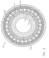
- a magnetic epicyclic gear arrangement or gearbox 110 includes an inner magnet ring 112, a middle or intermediate ring 114 and an outer magnet ring 116.
- Each ring (inner 112, middle 114 and outer 116) is constructed of a predetermined number of magnetic pole pieces 112a, 114a and 116a embedded at intervals along the ring structures 112, 114 and 116.
- the pole pieces 112a and 116a are composed of permanent magnets, and pole pieces 114a are composed of magnetically permeable material, the pole pieces 114a separated by magnetically non-permeable sectors 114b.
- the inner and outer ring structures 112, 116 are composed of magnetically permeable material.
- the magnetic gear box 110 has a fixed torque ratio defined by the number of poles in each of the rings 112, 114 and 116.
- the magnetic gear box 110 couples the HP and LP spools 21, 29 of a turbofan engine 10. Note that the fixed torque ratio applies but only in the situation where the rotational velocities of the rings 112, 114 and 116, satisfy Equation 1, which is set forth below. Since the forces in the engine are such that the speeds of the rotors are independent of one another, the ideal torque split is realized only when the intermediate ring is free to rotate with low enough load to preclude slip.
- the fixed torque ratio is an ideal property that describes where the magnetic gear box 110 tends to operate.
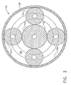
- the magnetic gear box 110 provides a fully passive magnetic equivalent of a mechanical epicyclic planetary gearbox 120, shown in Figure 3 .
- a high degree of magnetic coupling is achieved in the magnetic gear arrangement 110, which enables torque densities comparable to the mechanical epicyclic planetary gearbox 120.
- the magnetic gear box 110 operates without mechanical contact between the rings 112, 114 and 116, thus reducing mechanical vibration.
- the pullout torque allows the magnetic gear box 110 to slip, which permits a factor of safety compared with mechanical gear arrangements that jam and break when subjected to excessive torques.
- the magnetic gear box 110 has an inner ring 112, an intermediate ring 114 and an outer ring 116, which are analogous with the three main components of the mechanical epicyclic gearbox 120, i.e., the innermost "sun” gear 122, the middle "planet” carriers 124, and the outermost ring gear 126 correspond to the inner ring 112, an intermediate ring 114 and an outer ring 116, respectively.
- Each of the gears 122, 124 and 126 has teeth indicated as 122a, 124a and 126a, respectively.
- a planet carrier 121 is used to maintain uniform positions of the middle "planet" carriers 124 around the "sun” gear 122.
- each gear angular velocity ⁇ s , ⁇ p and ⁇ r is represented by a vertical axis 132, 134 and 136, respectively.
- ⁇ r number of teeth of the ring gear
- z s number of teeth of the sun gear
- the ordinate 140 of the carrier velocity ⁇ c is disposed along the horizontal axis 138 between the ordinates 142, 144 of the sun gear velocity ⁇ s , and the ring gear velocity ⁇ r .
- the carrier ordinate 140 divides the distance between the two outer ordinates 142, 144, in the ratio of 1 to - i 0 , as indicated by arrows 146, 148 beneath the horizontal axis 138.
- turbofan engine 10 having a variable magnetic gearbox 110 disposed between the HP spool 21 and the LP spool 29.
- the outer ring 116 of the magnetic gear box 110 is coupled to the HP spool 21, the inner ring 112 is coupled to the LP spool 29, and the third ring 114 is coupled to a motor/generator (M/G) 160.
- the engine 10 also includes a conventional gearbox 162 coupled with HP spool 21 for driving starter/generators 164, 166, which provide the primary source of electrical power for the aircraft systems.
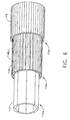
- the intermediate ring 114 is coupled to the M/G 160.
- the intermediate ring 114 may be split into two effective rings 114b and 114c, which may be controllably adjusted to advance or retard the phasing of the magnetic fields, for cancellation so that the intermediate ring 114 is allowed to free-wheel such that no coupling is provided between the engine spools 21, 29 by the magnetic gear box 110, or for adjusting the degree or percentage of coupling between the inner ring 112 and the outer ring 116.
- An alternate method is to provide a single, integrated ring 114 having interleaved poles 114b, 114c with an external phase control (not shown) for the respective magnetic fields.
- the ability to control the magnetic coupling between the shafts connected to the magnetic gear box 110, particularly by allowing the intermediate ring to free-wheel such that no coupling is provided between the shafts 21, 29 by the magnetic gear box 110, provides a safety feature when it is necessary to separate the two shafts, such as the HP spool 21 and the LP spool 29.
- the arrangement of the HP spool 21, LP spool 29 and the M/G may be selectively modified as discussed in further detail below, such that the inner ring 112, intermediate ring 114 and outer ring 116 are coupled with any of the HP spool 21, LP spool 29 and the M/G, to achieve alternate torque transfer characteristics.
- Inner ring 112 contains the LP spool magnets 112a.
- the poles 114b, 114c of the intermediate ring 114 are interleaved, as indicated by the coaxial striations 114b, 144c.
- the intermediate ring 114 is coupled to the M/G 160 and is used to control the relative distribution of torque between the HP spool 21 and the LP spool 29.
- the outer magnet ring 116 is coupled to the HP spool 21, and the inner magnet ring 112 is coupled to the LP spool 29.
- Each of the rings 112, 114 and 116 is coaxial and concentric, and is independently rotatable with respect to the others.
- the magnetic gear box 110 is configure so that the HP spool 21, which normally rotates at a higher speed than the LP spool 29, is coupled to the inner ring magnets 112 for driving the inner ring magnets 112 at a higher speed, and the LP spool 29 is coupled to the outer magnet ring 116 operating at lower speed than the HP spool 21.
- This relationship follows the natural gearing ratio of the magnetic gear box 10, for a fixed set of planetary teeth 122a, for example.
- the HP & LP spools 21, 29 may operate independently of one another, and at varying speeds.
- the intermediate magnet ring 114 is arranged to rotate independently as well.
- the intermediate magnet ring 114 will rotate at the angular velocity defined by Equations 1 and 2.
- Line 158 (See Figure 4 ) could pass through zero speed at some particular ratio of HP to LP speed.
- the applied torque on the movable intermediate ring 114 can be positive or negative to transfer power in the desired direction. This torque is applied to the spinning intermediate ring 114, and therefore power will flow in either direction at this location.
- the power source and the load for this transferred power must be supplied variably.
- a motor-generator 160 could be used to supply or to expend power in the intermediate ring 114, as shown in Figure 5 .
- this electrical power must be obtained from the existing electrical power system. In doing so, circulating power can result, in both mechanical and electrical form. Increases in power system weight and size may result if not carefully taken into account in the design.
- a variable torque coupler 200 varies the output torque applied to the intermediate ring 114 or other input to the epicyclic magnetic gear box 110.
- variable torque coupler 200 has rotating permanent magnets 202 for inputs, a rotating squirrel-cage-type induction rotor 204 drives an output shaft 206, and a sliding magnetic shield control (not shown).
- the rotor 204 slides on a keyed output shaft 206 to selectively control the output torque of the variable torque coupler 200.
- the output of this coupler 200 is applied through shaft 206 to the intermediate ring 114 input of the magnetic gear box 110, which thus controls the flow of power therethrough.
- variable torque coupler 200 In addition to the variable torque coupler 200, several other configurations may be employed, including continuously- and infinitely-variable mechanical transmissions, hydraulic transmissions, motor-generator combinations, and novel electromechanical arrangements.
- the present invention discloses an epicyclic magnetic gear box 110 in combination with a continuously variable method for controlling the flow of power therethrough.
- the application of this continuous variability may optionally be applied throughout the operating ranges of the HP and LP spools 21, 29, so that, for example, in some operating schemes the intermediate ring 114 may be fully free to rotate without any applied torque. Conversely, in other operating schemes, the intermediate ring 114 may be constrained to rotate in one direction, providing the torque necessary to maintain the speed ratio of the HP spool 21 to the LP spool 29 fixed.
- the fixed gear ratio of a magnetic gear box is made variable.
- the magnetic gear box 110 with a variable gear ratio provides the ability to control the transfer of power from a first mechanical rotating shaft to a second mechanical rotating shaft.
- additional gearing stages may be provided to allow optimization of engine spool operating speeds.
- the magnetic gear box 110 may provide a fixed ratio of torque transfer between the HP spool 21 and the LP spool 29 of the turbofan engine, wherein the third inputs such as the M/G 160 or the variable torque coupler 200 are not connected to the intermediate magnetic ring 114.
- the magnetic gear box 110 is coupled to the HP spool 21 and the LP spool 29. This arrangement extracts power from the HP spool 21 through the standard mechanical gearbox arrangement 162, wherein the gearbox 162 is coupled to one or more starters 168 or starter/generators 164.
- the LP spool 29 can provide the additional power via magnetic gearbox 110 such that the amount of power provided by the HP spool 21 is approximately constant, allowing the speed of the HP spool 21 to remain constant.”
- This has at least three beneficial effects, namely, (1) low acceleration time for increasing emergency thrust, (2) a high stability margin of the HP spool, and (3) reduced idle thrust due to decreasing LP spool speed.
- the torque coupling magnetic gear box 110 can be used internally to enhance performance and operability in other ways, e.g., transferring torque to optimize the power split between the HP turbine 23 and the LP turbine 27, or to utilize LP spool 21 as a power source/sink to aid in acceleration or deceleration of the core engine 18. Note that this configuration would not be used as a thrust control device for steady-state airspeed stability, as moving power to the fan while under fan speed control would rebalance the cycle. This could change the fuel flow, but it would not create more thrust.
- a three-spool turbofan (e.g., HP, LP and auxiliary) may be configured with the magnetic gearbox 110, such that any two spools of the three spools can be connected.
- two magnetic gearboxes 110 may be configured to connect any spool to the remaining two spools.
- a three spool turbofan may be configured such that one magnetic gearbox 110 can be connected to all three spools, with one ring 112, 114 and 116, connected to each spool.
- the input power to the magnetic gearbox 110 may be sourced from the third spool of a turbofan. Or in a two spool turbofan, a third, dependent spool that is formed by use of a gearbox may be employed to separate parts of the HP spool, such as with a geared fan or a geared booster.
- both rings rotate at the same speed in opposite directions.
- the ring speeds deviate slightly, one faster and one slower, and small restoring torques will tend to slow the fast axle and accelerate the slow axle. If one wheel breaks away, there will be some slip speed at which substantial torques act to transfer power from the slipping wheel to the wheel with traction generated to return the wheels to the same rotational speed.
- a multi-generator power system may be driven from one prime mover, wherein there is one master generator and the rest of the generators are slave generators.
- the coupling from the prime mover to the master generator is rigid and it is connected to a first ring of multiple magnetic gearboxes 110.
- the coupling or couplings between the prime mover and the slave generators will be torsionally flexible with limited range of tangential displacement from nominal.
- the slave generators are connected to one or more secondary rings of a similar number of magnetic gearboxes 110.
- the intermediate rings 114 are controlled to retard or advance the slave generators within said limited range of tangential displacement such that all slave generators are operating at identical phase angles to the master generator.
Landscapes
- Engineering & Computer Science (AREA)
- Chemical & Material Sciences (AREA)
- Combustion & Propulsion (AREA)
- Mechanical Engineering (AREA)
- General Engineering & Computer Science (AREA)
- Power Engineering (AREA)
- Dynamo-Electric Clutches, Dynamo-Electric Brakes (AREA)
- Retarders (AREA)
- Connection Of Motors, Electrical Generators, Mechanical Devices, And The Like (AREA)
- Turbine Rotor Nozzle Sealing (AREA)
- General Details Of Gearings (AREA)
Claims (8)
- Système, comprenant une paire d'arbres (LP, HP) tournant de façon indépendante et simultanée, et transmettant un couple entre eux, le système comprenant en outre :un engrenage magnétique (110), l'engrenage magnétique (110) comportant une première structure de bague (116), une deuxième structure de bague (112) et une structure de bague intermédiaire (114), chacune des première (116) et deuxième (112) structures de bague et de la structure de bague intermédiaire (114) présentant une ouverture annulaire, qui les traverse, et plusieurs pièces polaires magnétiques (112a, 114a, 116a) encastrées dans ces structures, la structure de bague intermédiaire (114) étant disposée entre la première structure de bague (116) et la deuxième structure de bague (112), chacune des première (116) et deuxième (112) structures de bague et de la structure de bague intermédiaire (114) étant disposée de façon coaxiale et concentrique et avec possibilité de rotation indépendante par rapport aux deux autres structures de bague;les première (116) et deuxième (112) structures de bague étant accouplées chacune à des arbres séparés parmi les arbres tournants, et la structure de bague intermédiaire (114) coopérant avec la première structure de bague (116) et la deuxième structure de bague (112) et déterminant le niveau du couple transmis entre la paire d'arbres tournants, caractérisé en ce quela structure de bague intermédiaire (114) est accouplée à une machine tournante (200 - fig. 7,B), la machine tournante comportant un contrôleur et pouvant être actionnée pour régler le niveau du couple transmis entre la paire d'arbres tournants (LP, HP);où la machine tournante (200) comprend une partie formant rotor (204) et une troisième structure de bague annulaire présentant plusieurs aimants permanents (202) qui y sont encastrés, la partie rotor (204) comprenant un arbre de sortie (206) et étant configurée pour se déplacer dans deux directions le long d'un axe de la machine tournante, pour coupler magnétiquement la partie rotor (204) dans la troisième structure de bague annulaire, la troisième structure de bague annulaire étant accouplée en vue de l'entraînement à l'un (HP) des arbres (LP, HP) tournant de façon indépendante, afin d'induire un champ électromagnétique dans la partie rotor (204) pour régler de manière sélective un couple de sortie de l'arbre de sortie (206), et l'arbre de sortie (206) de la partie rotor (204) étant accouplé à la structure de bague intermédiaire (114).
- Système selon la revendication 1, dans lequel la partie rotor (204) est un rotor à induction de type à cage d'écureuil.
- Système selon la revendication 1, dans lequel la machine tournante est un moteur/générateur (160) configuré pour recevoir du courant de la structure de bague intermédiaire (114) et pour fournir du courant à celle-ci, en réponse à un signal produit par le contrôleur, de manière à ce que le couple soit transmis de façon variable entre la paire d'arbres tournants.
- Système selon la revendication 1, dans lequel la transmission magnétique (110) est constituée d'un équivalent magnétique totalement passif d'un train planétaire épicycloïdal mécanique.
- Système selon la revendication 1, dans lequel les première (116) et deuxième (112) structures de bague et la structure de bague intermédiaire (114) ont des vitesses angulaires ωr, ωs et ωc qui sont mises en relation par l'équation suivante :

où le rapport est i0 = zr/zs, et zr/zs est un rapport défini par le nombre d'aimants permanents (202) dans la première structure de bague (116), sur une bague planétaire extérieure de l'engrenage magnétique (110), par rapport au nombre d'aimants permanents (202) dans la deuxième structure de bague (112). - Système selon la revendication 5, dans lequel les couples Tr, Ts et Tc correspondent à la première structure de bague (116), à la deuxième structure de bague (112) et à la structure de bague intermédiaire (114) et exercent un couple sur les première (116) et deuxième (112) structures de bague et sur la structure de bague intermédiaire (114), conformément à l'équation suivante :

- Moteur (10) comprenant le système selon la revendication 1, dans lequel les arbres tournants (LP, HP) sont des arbres tournants du moteur.
- Moteur (10) selon la revendication 7, dans lequel le moteur (10) est un moteur d'avion à turboréacteur à double flux qui est doté d'une turbine haute pression (23), accouplée au premier arbre, et une turbine basse pression (27) accouplée au deuxième arbre.
Applications Claiming Priority (1)
| Application Number | Priority Date | Filing Date | Title |
|---|---|---|---|
| US11/615,627 US7791235B2 (en) | 2006-12-22 | 2006-12-22 | Variable magnetic coupling of rotating machinery |
Publications (3)
| Publication Number | Publication Date |
|---|---|
| EP1936238A2 EP1936238A2 (fr) | 2008-06-25 |
| EP1936238A3 EP1936238A3 (fr) | 2011-06-15 |
| EP1936238B1 true EP1936238B1 (fr) | 2013-04-17 |
Family
ID=39154380
Family Applications (1)
| Application Number | Title | Priority Date | Filing Date |
|---|---|---|---|
| EP07123135.1A Not-in-force EP1936238B1 (fr) | 2006-12-22 | 2007-12-13 | Couplage magnétique variable de machinerie rotative |
Country Status (5)
| Country | Link |
|---|---|
| US (1) | US7791235B2 (fr) |
| EP (1) | EP1936238B1 (fr) |
| JP (1) | JP5188169B2 (fr) |
| CN (1) | CN101222172B (fr) |
| CA (1) | CA2613767C (fr) |
Cited By (1)
| Publication number | Priority date | Publication date | Assignee | Title |
|---|---|---|---|---|
| US9890704B2 (en) | 2013-05-01 | 2018-02-13 | Derwent Aviation Consulting Ltd. | Compressor system |
Families Citing this family (115)
| Publication number | Priority date | Publication date | Assignee | Title |
|---|---|---|---|---|
| FR2915523A1 (fr) * | 2007-04-27 | 2008-10-31 | Snecma Sa | Dispositif de production d'energie electrique dans un moteur a turbine a gaz a double corps |
| US8337147B2 (en) | 2007-09-21 | 2012-12-25 | United Technologies Corporation | Gas turbine engine compressor arrangement |
| US8277174B2 (en) | 2007-09-21 | 2012-10-02 | United Technologies Corporation | Gas turbine engine compressor arrangement |
| US20140157754A1 (en) | 2007-09-21 | 2014-06-12 | United Technologies Corporation | Gas turbine engine compressor arrangement |
| GB0800463D0 (en) * | 2008-01-11 | 2008-02-20 | Magnomatics Ltd | Magnetic drive systems |
| GB2457682B (en) * | 2008-02-21 | 2012-03-28 | Magnomatics Ltd | Variable magnetic gears |
| GB0813173D0 (en) * | 2008-02-21 | 2008-08-27 | Magnomatics Ltd | Wind turbine power train |
| GB0810097D0 (en) | 2008-06-03 | 2008-07-09 | Magnomatics Ltd | Magnetic gear |
| GB0808524D0 (en) * | 2008-05-12 | 2008-06-18 | Magnomatics Ltd | Magnetic pole-piece structure |
| US20140174056A1 (en) | 2008-06-02 | 2014-06-26 | United Technologies Corporation | Gas turbine engine with low stage count low pressure turbine |
| US8128021B2 (en) | 2008-06-02 | 2012-03-06 | United Technologies Corporation | Engine mount system for a turbofan gas turbine engine |
| DE102008028883A1 (de) * | 2008-06-18 | 2009-12-24 | Rolls-Royce Deutschland Ltd & Co Kg | Gasturbine mit zumindest einer mehrstufigen, mehrere Verdichtermodule umfassenden Verdichtereinheit |
| DE102008031932A1 (de) * | 2008-07-07 | 2010-01-14 | Rolls-Royce Deutschland Ltd & Co Kg | Gasturbine mit zumindest einer mehrstufigen, mehrere Verdichtermodule umfassenden Verdichtereinheit |
| US8143738B2 (en) * | 2008-08-06 | 2012-03-27 | Infinite Wind Energy LLC | Hyper-surface wind generator |
| GB0814399D0 (en) * | 2008-08-08 | 2008-09-10 | Rolls Royce Plc | Variable gear ratio magnetic gearbox |
| US8019522B2 (en) * | 2008-09-30 | 2011-09-13 | General Electric Company | Method and system for providing cooling and power |
| EP2177735A3 (fr) * | 2008-10-20 | 2012-02-15 | Rolls-Royce North American Technologies, Inc. | Turbosoufflante |
| US8203316B2 (en) * | 2008-12-18 | 2012-06-19 | Hamilton Sundstrand Corporation | Eddy current torsional damper for generator |
| GB0900022D0 (en) * | 2009-01-05 | 2009-02-11 | Rolls Royce Plc | Management gear arrangement |
| US20100192595A1 (en) | 2009-01-30 | 2010-08-05 | Robert Joseph Orlando | Gas turbine engine assembly and methods of assembling same |
| GB0903830D0 (en) * | 2009-03-06 | 2009-04-22 | Cummins Turbo Tech Ltd | Gas expander system |
| JP5309293B2 (ja) * | 2009-06-24 | 2013-10-09 | 宮城県 | 動力伝達装置 |
| GB2474286B (en) | 2009-10-12 | 2011-08-31 | Rolls Royce Plc | A propulsion engine |
| US8188629B2 (en) * | 2010-03-03 | 2012-05-29 | Industrial Technology Research Institute | Magnetic transmission assembly |
| US8541922B2 (en) * | 2010-03-03 | 2013-09-24 | Industrial Technology Research Institute | Magnetic transmission assembly |
| JP5286373B2 (ja) * | 2011-01-28 | 2013-09-11 | 株式会社日立製作所 | 磁気歯車 |
| US9239012B2 (en) | 2011-06-08 | 2016-01-19 | United Technologies Corporation | Flexible support structure for a geared architecture gas turbine engine |
| US9631558B2 (en) | 2012-01-03 | 2017-04-25 | United Technologies Corporation | Geared architecture for high speed and small volume fan drive turbine |
| US9021778B2 (en) | 2011-06-28 | 2015-05-05 | United Technologies Corporation | Differential gear system with carrier drive |
| US8723385B2 (en) | 2011-10-07 | 2014-05-13 | General Electric Company | Generator |
| US8723349B2 (en) | 2011-10-07 | 2014-05-13 | General Electric Company | Apparatus for generating power from a turbine engine |
| US8464511B1 (en) | 2012-01-06 | 2013-06-18 | Hamilton Sundstrand Corporation | Magnetically coupled contra-rotating propulsion stages |
| US20130186058A1 (en) * | 2012-01-24 | 2013-07-25 | William G. Sheridan | Geared turbomachine fan and compressor rotation |
| EP2820232A4 (fr) * | 2012-03-02 | 2016-03-02 | Nat Oilwell Varco Lp | Dispositifs de disque magnétique et systèmes et procédés associés |
| CA2865906A1 (fr) * | 2012-03-02 | 2013-09-06 | National Oilwell Varco, L.P. | Engrenages magnetiques et systemes et procedes associes |
| US20130232941A1 (en) * | 2012-03-07 | 2013-09-12 | Ge Aviation Systems Llc | Apparatus for extracting input power from the low pressure spool of a turbine engine |
| CN104221269B (zh) * | 2012-03-27 | 2017-07-25 | 日立金属株式会社 | 频率转换装置 |
| US10125693B2 (en) | 2012-04-02 | 2018-11-13 | United Technologies Corporation | Geared turbofan engine with power density range |
| GB201207754D0 (en) * | 2012-05-03 | 2012-06-13 | Rolls Royce Plc | Electro-magnetic coupling system |
| US8756908B2 (en) | 2012-05-31 | 2014-06-24 | United Technologies Corporation | Fundamental gear system architecture |
| US8572943B1 (en) | 2012-05-31 | 2013-11-05 | United Technologies Corporation | Fundamental gear system architecture |
| US9239007B2 (en) * | 2012-05-31 | 2016-01-19 | General Electric Company | Gas turbine compressor inlet pressurization having a torque converter system |
| US20150308351A1 (en) | 2012-05-31 | 2015-10-29 | United Technologies Corporation | Fundamental gear system architecture |
| IN2015KN00237A (fr) | 2012-06-27 | 2015-06-12 | Pentair Water Pool & Spa Inc | |
| EP2877716A4 (fr) | 2012-07-24 | 2015-08-12 | Brent Wei-Teh Lee | Moteur à détonation interne, moteurs hybrides le comprenant et leurs procédés de fabrication et d'utilisation |
| GB201219544D0 (en) * | 2012-10-31 | 2012-12-12 | Rolls Royce Deutschland | Geared compressor for gas turbine engine |
| US9045996B2 (en) | 2012-11-20 | 2015-06-02 | Honeywell International Inc. | Gas turbine engine optimization by electric power transfer |
| US9752832B2 (en) | 2012-12-21 | 2017-09-05 | Elwha Llc | Heat pipe |
| US9404392B2 (en) | 2012-12-21 | 2016-08-02 | Elwha Llc | Heat engine system |
| US20160006335A1 (en) * | 2013-01-11 | 2016-01-07 | Hitachi Metals, Ltd. | Magnetic gear device |
| BR112015017110A2 (pt) | 2013-01-18 | 2017-07-11 | Gen Electric | motor de turbina a gás |
| WO2014143219A1 (fr) * | 2013-03-13 | 2014-09-18 | Phillips Steven D | Contrôle de santé de moteur et commande d'attribution de puissance pour un moteur à turbine à l'aide de générateurs électriques |
| EP3019709B1 (fr) | 2013-07-07 | 2022-05-11 | Raytheon Technologies Corporation | Dispositif de commande mécanique pour système d'engrenage d'entraînement de ventilateur |
| EP3039276B1 (fr) * | 2013-08-29 | 2019-12-25 | United Technologies Corporation | Réacteur triple corps à réducteur avec pignon de commande de compresseur basse pression et contrôleur mécanique |
| US20150300264A1 (en) | 2013-09-30 | 2015-10-22 | United Technologies Corporation | Geared turbofan architecture for regional jet aircraft |
| CN103580448B (zh) * | 2013-10-21 | 2015-09-30 | 苏州科睿特能源科技有限公司 | 一种柔性扭矩传递装置 |
| CN103532339B (zh) * | 2013-10-21 | 2016-05-18 | 苏州科睿特能源科技有限公司 | 一种柔性动力传递装置 |
| US10267228B2 (en) | 2013-10-31 | 2019-04-23 | United Technologies Corporation | Geared turbofan arrangement with core split power ratio |
| US10502163B2 (en) | 2013-11-01 | 2019-12-10 | United Technologies Corporation | Geared turbofan arrangement with core split power ratio |
| WO2015112212A2 (fr) | 2013-11-01 | 2015-07-30 | United Technologies Corporation | Agencement de réacteur à réducteur présentant un rapport de puissance divisé par noyau |
| WO2015121647A1 (fr) | 2014-02-11 | 2015-08-20 | Magnomatics Limited | Système d'engrenage magnétique et procédé de réduction de transmission de pulsation de couple |
| GB2523088A (en) * | 2014-02-11 | 2015-08-19 | Magnomatics Ltd | Magnetic power-split |
| US9869190B2 (en) | 2014-05-30 | 2018-01-16 | General Electric Company | Variable-pitch rotor with remote counterweights |
| DE102014210299A1 (de) * | 2014-05-30 | 2015-12-03 | Mahle International Gmbh | Magnetkupplung |
| EP3161321B1 (fr) | 2014-06-24 | 2019-03-13 | Grundfos Holding A/S | Un engrenage magnétique |
| AU2014240249B1 (en) * | 2014-10-02 | 2015-04-23 | Zenin, Vladimir Mr | Magnet engine |
| US10072510B2 (en) | 2014-11-21 | 2018-09-11 | General Electric Company | Variable pitch fan for gas turbine engine and method of assembling the same |
| FR3029172B1 (fr) * | 2014-11-27 | 2018-05-25 | Safran Helicopter Engines | Groupe propulseur a moyens d'accouplement selectif |
| CN104632464B (zh) * | 2015-01-29 | 2017-03-08 | 西北工业大学 | 一种电磁互带转动装置 |
| US20160258356A1 (en) * | 2015-03-05 | 2016-09-08 | Rolls-Royce North American Technologies, Inc. | Gas turbine engine with magnetic gearbox |
| WO2016164932A1 (fr) * | 2015-04-10 | 2016-10-13 | Lugg Richard H | Turbine électrique à jet hypersonique, de génération avancée |
| GB2541225B (en) * | 2015-08-13 | 2019-05-29 | Jaguar Land Rover Ltd | Supercharger Assembly comprising a Magnetic Gear |
| US10100653B2 (en) | 2015-10-08 | 2018-10-16 | General Electric Company | Variable pitch fan blade retention system |
| US20170107845A1 (en) * | 2015-10-15 | 2017-04-20 | General Electric Company | Systems and methods to facilitate enhancing turbine output using an auxiliary generator |
| US10273883B2 (en) | 2016-02-26 | 2019-04-30 | The Boeing Company | Engine accessory drives systems and methods |
| US11014513B2 (en) * | 2016-05-18 | 2021-05-25 | Rolls-Royce North American Technologies Inc. | Control of low pressure generator for gas turbine engine |
| GB2551545B (en) * | 2016-06-21 | 2022-03-09 | Lynley Ashley Adrian | Servo differential turbofan engine |
| CN110291282B (zh) * | 2016-12-15 | 2021-12-31 | 通用电气航空系统有限责任公司 | 具有分离器的空气涡轮启动器 |
| US10975717B2 (en) * | 2016-12-19 | 2021-04-13 | General Electric Company | Torque monitoring device for a gas turbine engine |
| US10519866B2 (en) | 2017-05-15 | 2019-12-31 | Unison Industries, Llc | Decoupler assemblies for engine starter |
| GB201708289D0 (en) * | 2017-05-24 | 2017-07-05 | Rolls Royce Plc | Preventing electrical breakdown |
| DE102017208985A1 (de) * | 2017-05-29 | 2018-11-29 | Deere & Company | Magnetisches Umlaufgetriebe mit variierbarem Drehmoment |
| US11230385B2 (en) * | 2017-06-08 | 2022-01-25 | General Electric Company | Hybrid-electric propulsion system for an aircraft |
| US10174629B1 (en) | 2017-09-11 | 2019-01-08 | United Technologies Corporation | Phonic seal seat |
| US11008883B2 (en) | 2017-09-20 | 2021-05-18 | General Electric Company | Turbomachine with a gearbox and integrated electric machine assembly |
| GB2568093A (en) * | 2017-11-06 | 2019-05-08 | Rolls Royce Plc | Multi-shaft gas turbine engine |
| DE102018110151A1 (de) * | 2018-04-26 | 2019-10-31 | Linz Center Of Mechatronics Gmbh | Elektrische Maschine mit Elektromotor und Magnetgetriebe |
| BE1026407B1 (fr) * | 2018-06-22 | 2020-01-28 | Safran Aero Boosters Sa | Turbomachine a transmission hybride |
| RU2708416C1 (ru) * | 2018-09-04 | 2019-12-06 | Дмитрий Леонидович Егоров | Механизм для преобразования неравномерного движения двух и более рабочих органов устройства в равномерное вращение выходного вала этого устройства с функцией предохранения и его работа (варианты) |
| FR3086340B1 (fr) * | 2018-09-21 | 2021-02-26 | Safran Aircraft Engines | Turboreacteur comprenant un dispositif d'apport de puissance |
| FR3086348B1 (fr) | 2018-09-21 | 2020-12-04 | Safran Aircraft Engines | Turboreacteur a reducteur |
| EP3853466A1 (fr) * | 2018-09-21 | 2021-07-28 | Safran Aircraft Engines | Turboréacteur comprenant un dispositif d'apport de puissance |
| US11015532B2 (en) | 2018-10-18 | 2021-05-25 | Rolls-Royce North American Technologies, Inc. | Parallel starter/generator and air turbine starter |
| US11261795B2 (en) | 2018-10-18 | 2022-03-01 | Rolls-Royce North American Technologies, Inc. | Dual mode starter generator |
| US12024302B2 (en) * | 2018-10-26 | 2024-07-02 | Rolls-Royce Corporation | Hybrid starter motor-generator |
| US11067006B2 (en) | 2019-03-05 | 2021-07-20 | Rolls-Royce Corporation | Gas turbine engine system with synchronization features for gearbox operation |
| US11110800B2 (en) * | 2019-04-04 | 2021-09-07 | Ford Global Technologies, Llc | Method for auxiliary load control |
| US11046404B2 (en) | 2019-07-31 | 2021-06-29 | Abb Schweiz Ag | Dual propeller drive system for a ship |
| GB2589193B (en) * | 2019-08-23 | 2022-09-21 | Raytheon Tech Corp | Augmented drive of compressors via differential and multistage turbine |
| US11421590B2 (en) * | 2019-08-23 | 2022-08-23 | Raytheon Technologies Corporation | Augmented drive of compressors via differential and multistage turbine |
| US11296588B2 (en) * | 2019-10-15 | 2022-04-05 | Darrell Schmidt Enterprises, Inc. | Magnetic coupler |
| US11522436B2 (en) | 2019-10-15 | 2022-12-06 | Darrell Schmidt Enterprises, Inc. | Permanently magnetized enhanced generator |
| GB201917774D0 (en) | 2019-12-05 | 2020-01-22 | Rolls Royce Plc | Gas turbine engine arrangement |
| GB201917773D0 (en) | 2019-12-05 | 2020-01-22 | Rolls Royce Plc | High power epicyclic gearbox and operation thereof |
| GB201917765D0 (en) | 2019-12-05 | 2020-01-22 | Rolls Royce Plc | Aircraft engine |
| GB201917764D0 (en) | 2019-12-05 | 2020-01-22 | Rolls Royce Plc | Reliable gearbox for gas turbine engine |
| CN110748417B (zh) * | 2019-12-24 | 2020-04-10 | 沈阳微控新能源技术有限公司 | 一种基于磁耦合联轴器的涡轮增压器和发动机 |
| US11454172B2 (en) | 2019-12-26 | 2022-09-27 | Unison Industries, Llc | Starter/generator system |
| CN111585385B (zh) * | 2020-05-27 | 2021-07-30 | 苏州维斯勒姆智能科技有限公司 | 一种电磁摩擦抵消传动辅助装置 |
| US11781506B2 (en) | 2020-06-03 | 2023-10-10 | Rtx Corporation | Splitter and guide vane arrangement for gas turbine engines |
| IT202000020596A1 (it) * | 2020-08-28 | 2022-02-28 | Nuovo Pignone Tecnologie Srl | Metodo per far funzionare un sistema a treno per un’attrezzatura ad azionamento meccanico |
| US11428160B2 (en) | 2020-12-31 | 2022-08-30 | General Electric Company | Gas turbine engine with interdigitated turbine and gear assembly |
| US11674435B2 (en) | 2021-06-29 | 2023-06-13 | General Electric Company | Levered counterweight feathering system |
| US11795964B2 (en) | 2021-07-16 | 2023-10-24 | General Electric Company | Levered counterweight feathering system |
| CN113890294B (zh) * | 2021-10-27 | 2024-05-10 | 华北电力大学 | 一种电流调制型同心磁齿轮结构及其电流控制方法 |
Family Cites Families (36)
| Publication number | Priority date | Publication date | Assignee | Title |
|---|---|---|---|---|
| US1697292A (en) * | 1919-12-17 | 1929-01-01 | Elmer A Sperry | Engine and the transmission of power therefrom |
| US2311331A (en) * | 1937-03-01 | 1943-02-16 | Asea Ab | Means for measuring the torque of combustion engines |
| US2523046A (en) | 1946-03-06 | 1950-09-19 | Allis Chalmers Mfg Co | Control system for dynamoelectric machines with differentially excited fields |
| US2689920A (en) | 1951-04-04 | 1954-09-21 | Eaton Mfg Co | Electromagnetic slip-coupling control |
| FR1498392A (fr) | 1966-06-22 | 1967-10-20 | Perfectionnements aux ralentisseurs, aux freins et aux coupleurs à glissement permanent | |
| GB1489055A (en) * | 1973-08-17 | 1977-10-19 | Pont Res & Investment Services | Magnetic coupling |
| FR2540951B1 (fr) | 1983-02-16 | 1988-12-02 | Renault | Dispositif electromagnetique de commande d'embrayage en effort |
| US4864812A (en) * | 1987-11-13 | 1989-09-12 | Sundstrand Corporation | Combined auxiliary and emergency power unit |
| US4808869A (en) * | 1987-11-18 | 1989-02-28 | Sundstrand Corp. | Integral magnetic torque limiting coupling/motor |
| DE3841508A1 (de) * | 1988-12-09 | 1990-06-13 | Walter Stuke | Drehmoment-uebertragungsgetriebe |
| US5834872A (en) | 1993-05-21 | 1998-11-10 | Magna Force, Inc. | Adjustable magnetic coupler |
| USRE37743E1 (en) | 1994-10-03 | 2002-06-11 | Tai-Her Yang | Distributed differential mixing combined power system |
| US5569111A (en) * | 1994-10-11 | 1996-10-29 | The United States Of America As Represented By The Secretary Of The Navy | Permanent magnet torque/force transfer apparatus |
| US5523638A (en) | 1994-10-11 | 1996-06-04 | Albrecht; James W. | Shaft mounted eddy current drive with rotary electrical connector |
| US5508574A (en) | 1994-11-23 | 1996-04-16 | Vlock; Alexander | Vehicle transmission system with variable speed drive |
| JP3434602B2 (ja) | 1995-01-13 | 2003-08-11 | 株式会社東芝 | 変速装置 |
| DE19604710A1 (de) | 1996-02-09 | 1997-08-14 | Ingelheim Peter Graf Von | Elektromagnetisches Getriebe mit verstellbarem Drehmoment |
| TW355869B (en) | 1996-11-16 | 1999-04-11 | Gerd Schuessler | Magnetic planetarization method |
| DE19652490A1 (de) * | 1996-12-17 | 1998-06-18 | Philips Patentverwaltung | Magnetisches Getriebe |
| US6121705A (en) * | 1996-12-31 | 2000-09-19 | Hoong; Fong Chean | Alternating pole AC motor/generator with two inner rotating rotors and an external static stator |
| DE19717340A1 (de) | 1997-04-24 | 1998-10-29 | Erich Mehnert | Getriebe-Zahnrad |
| JPH10314569A (ja) * | 1997-05-16 | 1998-12-02 | Hiroshi Miyauchi | 撹拌装置 |
| US5947248A (en) | 1997-08-29 | 1999-09-07 | American Cooling Systems, Llc | Electric fan clutch |
| WO1999014847A1 (fr) | 1997-09-18 | 1999-03-25 | Mildice James W | Systeme machine universelle a vitesse variable |
| EP0954087A1 (fr) * | 1998-04-30 | 1999-11-03 | Sulzer Innotec Ag | Transmission dynamoélectrique et pompe centrifuge avec une telle transmission |
| DE19905862A1 (de) | 1999-02-12 | 2000-08-17 | Adwest Heidemann Einbeck Gmbh | Vorrichtung zum elektromechanischen Schalten eines Gangwechselgetriebes |
| JP3458891B2 (ja) * | 1999-05-19 | 2003-10-20 | ウシオ電機株式会社 | エキシマレーザ装置の磁気カップリング機構 |
| FR2826052B1 (fr) * | 2001-06-19 | 2003-12-19 | Snecma Moteurs | Dispositif de secours au rallumage d'un turboreacteur en autorotation |
| EP1477705B8 (fr) * | 2002-02-21 | 2011-01-26 | Ebara Corporation | Dispositif de mise en marche comprenant un dispositif de train planétaire différentiel et procédé de mise en marche de dispositif de train planétaire différentiel |
| DE10215488A1 (de) | 2002-04-09 | 2003-10-23 | Uli Streich | Magnetisches Getriebe |
| GB0208565D0 (en) | 2002-04-13 | 2002-05-22 | Rolls Royce Plc | A compact electrical machine |
| US6895741B2 (en) * | 2003-06-23 | 2005-05-24 | Pratt & Whitney Canada Corp. | Differential geared turbine engine with torque modulation capability |
| JP4434815B2 (ja) * | 2004-03-31 | 2010-03-17 | 本田技研工業株式会社 | ガスタービン・エンジンの制御装置 |
| JP2005315370A (ja) * | 2004-04-30 | 2005-11-10 | Chugoku Electric Power Co Inc:The | 動力伝達装置 |
| FR2882096B1 (fr) * | 2005-02-11 | 2012-04-20 | Snecma Moteurs | Turbomoteur a double corps avec des moyens de prise de mouvement sur les rotors basse pression et haute pression, module de prise de mouvement pour le turbomoteur et procede de montage du turbomoteur |
| CN2845305Y (zh) * | 2005-03-03 | 2006-12-06 | 广州汽车工业集团有限公司 | 电磁耦合无级变速器 |
-
2006
- 2006-12-22 US US11/615,627 patent/US7791235B2/en active Active
-
2007
- 2007-12-06 CA CA2613767A patent/CA2613767C/fr active Active
- 2007-12-13 EP EP07123135.1A patent/EP1936238B1/fr not_active Not-in-force
- 2007-12-21 JP JP2007329436A patent/JP5188169B2/ja not_active Expired - Fee Related
- 2007-12-21 CN CN2007103053532A patent/CN101222172B/zh not_active Expired - Fee Related
Cited By (1)
| Publication number | Priority date | Publication date | Assignee | Title |
|---|---|---|---|---|
| US9890704B2 (en) | 2013-05-01 | 2018-02-13 | Derwent Aviation Consulting Ltd. | Compressor system |
Also Published As
| Publication number | Publication date |
|---|---|
| CA2613767C (fr) | 2015-05-19 |
| EP1936238A2 (fr) | 2008-06-25 |
| EP1936238A3 (fr) | 2011-06-15 |
| JP5188169B2 (ja) | 2013-04-24 |
| CN101222172B (zh) | 2013-03-27 |
| CA2613767A1 (fr) | 2008-06-22 |
| US7791235B2 (en) | 2010-09-07 |
| US20080149445A1 (en) | 2008-06-26 |
| JP2008157458A (ja) | 2008-07-10 |
| CN101222172A (zh) | 2008-07-16 |
Similar Documents
| Publication | Publication Date | Title |
|---|---|---|
| EP1936238B1 (fr) | Couplage magnétique variable de machinerie rotative | |
| CA2612030C (fr) | Accouplement variable de corps de reacteur a double flux par differentiel libre ou train epicycloidal avec accouplement par couple pour captation de la puissance et exploitabilitedu reacteur | |
| EP3835562B1 (fr) | Système de propulsion hybride d'aéronef | |
| CA2612040C (fr) | Turboreacteur a double paroi pour aeronefs | |
| CA2612041C (fr) | Transmission a variation electromagnetique | |
| EP1936150B1 (fr) | Générateurs grande vitesse à nombre élevé de pôles | |
| US8324746B2 (en) | Variable drive gas turbine engine | |
| EP2320067B1 (fr) | Alternateur-démarreur d'avion | |
| CN110636971A (zh) | 用于包括具有安装在两个轴上的可逆电机的马达的飞行器的混合式推进结构 | |
| WO2009067048A1 (fr) | Moteur à turbine à gaz | |
| CA3146012A1 (fr) | Groupe motopropulseur hybride pour aeronef | |
| CN114026313A (zh) | 包括具有起动器-发电机功能的电机的涡轮机以及用于控制这种电机的速度的方法 | |
| EP3540198B1 (fr) | Système générateur de puissance électrique | |
| EP4036392A1 (fr) | Centrale électrique hybride pour aéronef | |
| EP3722577B1 (fr) | Moteur à turbine à gaz à entraînement multiple variable | |
| US4817459A (en) | Engine starting and power generating system |
Legal Events
| Date | Code | Title | Description |
|---|---|---|---|
| PUAI | Public reference made under article 153(3) epc to a published international application that has entered the european phase |
Free format text: ORIGINAL CODE: 0009012 |
|
| AK | Designated contracting states |
Kind code of ref document: A2 Designated state(s): AT BE BG CH CY CZ DE DK EE ES FI FR GB GR HU IE IS IT LI LT LU LV MC MT NL PL PT RO SE SI SK TR |
|
| AX | Request for extension of the european patent |
Extension state: AL BA HR MK RS |
|
| RIN1 | Information on inventor provided before grant (corrected) |
Inventor name: QU, RONGHAI Inventor name: CHUNG, KIYOUNG Inventor name: DE BEDOUT, JUAN M. Inventor name: KERN, JOHN M. Inventor name: TOOT, PETER D. Inventor name: WU, WEI Inventor name: SHAH, MANOJ Inventor name: THE OTHER INVENTORS HAVE AGREED TO WAIVE THEIR ENT |
|
| PUAL | Search report despatched |
Free format text: ORIGINAL CODE: 0009013 |
|
| AK | Designated contracting states |
Kind code of ref document: A3 Designated state(s): AT BE BG CH CY CZ DE DK EE ES FI FR GB GR HU IE IS IT LI LT LU LV MC MT NL PL PT RO SE SI SK TR |
|
| AX | Request for extension of the european patent |
Extension state: AL BA HR MK RS |
|
| 17P | Request for examination filed |
Effective date: 20111215 |
|
| AKX | Designation fees paid |
Designated state(s): DE FR GB |
|
| RIC1 | Information provided on ipc code assigned before grant |
Ipc: F02C 7/32 20060101ALI20120523BHEP Ipc: F16H 49/00 20060101AFI20120523BHEP Ipc: H02K 49/10 20060101ALI20120523BHEP Ipc: F01D 15/10 20060101ALI20120523BHEP Ipc: F02C 3/113 20060101ALI20120523BHEP Ipc: F02C 7/36 20060101ALI20120523BHEP Ipc: F02K 3/00 20060101ALI20120523BHEP |
|
| GRAP | Despatch of communication of intention to grant a patent |
Free format text: ORIGINAL CODE: EPIDOSNIGR1 |
|
| GRAP | Despatch of communication of intention to grant a patent |
Free format text: ORIGINAL CODE: EPIDOSNIGR1 |
|
| GRAS | Grant fee paid |
Free format text: ORIGINAL CODE: EPIDOSNIGR3 |
|
| GRAA | (expected) grant |
Free format text: ORIGINAL CODE: 0009210 |
|
| AK | Designated contracting states |
Kind code of ref document: B1 Designated state(s): DE FR GB |
|
| REG | Reference to a national code |
Ref country code: GB Ref legal event code: FG4D |
|
| REG | Reference to a national code |
Ref country code: DE Ref legal event code: R096 Ref document number: 602007029792 Country of ref document: DE Effective date: 20130613 |
|
| PLBE | No opposition filed within time limit |
Free format text: ORIGINAL CODE: 0009261 |
|
| STAA | Information on the status of an ep patent application or granted ep patent |
Free format text: STATUS: NO OPPOSITION FILED WITHIN TIME LIMIT |
|
| 26N | No opposition filed |
Effective date: 20140120 |
|
| REG | Reference to a national code |
Ref country code: DE Ref legal event code: R097 Ref document number: 602007029792 Country of ref document: DE Effective date: 20140120 |
|
| REG | Reference to a national code |
Ref country code: FR Ref legal event code: PLFP Year of fee payment: 9 |
|
| REG | Reference to a national code |
Ref country code: FR Ref legal event code: PLFP Year of fee payment: 10 |
|
| REG | Reference to a national code |
Ref country code: FR Ref legal event code: PLFP Year of fee payment: 11 |
|
| PGFP | Annual fee paid to national office [announced via postgrant information from national office to epo] |
Ref country code: DE Payment date: 20191119 Year of fee payment: 13 |
|
| PGFP | Annual fee paid to national office [announced via postgrant information from national office to epo] |
Ref country code: FR Payment date: 20191120 Year of fee payment: 13 |
|
| PGFP | Annual fee paid to national office [announced via postgrant information from national office to epo] |
Ref country code: GB Payment date: 20191122 Year of fee payment: 13 |
|
| REG | Reference to a national code |
Ref country code: DE Ref legal event code: R119 Ref document number: 602007029792 Country of ref document: DE |
|
| GBPC | Gb: european patent ceased through non-payment of renewal fee |
Effective date: 20201213 |
|
| PG25 | Lapsed in a contracting state [announced via postgrant information from national office to epo] |
Ref country code: FR Free format text: LAPSE BECAUSE OF NON-PAYMENT OF DUE FEES Effective date: 20201231 |
|
| PG25 | Lapsed in a contracting state [announced via postgrant information from national office to epo] |
Ref country code: GB Free format text: LAPSE BECAUSE OF NON-PAYMENT OF DUE FEES Effective date: 20201213 Ref country code: DE Free format text: LAPSE BECAUSE OF NON-PAYMENT OF DUE FEES Effective date: 20210701 |