EP1936144B1 - Spark ignition engine - Google Patents
Spark ignition engine Download PDFInfo
- Publication number
- EP1936144B1 EP1936144B1 EP06797044A EP06797044A EP1936144B1 EP 1936144 B1 EP1936144 B1 EP 1936144B1 EP 06797044 A EP06797044 A EP 06797044A EP 06797044 A EP06797044 A EP 06797044A EP 1936144 B1 EP1936144 B1 EP 1936144B1
- Authority
- EP
- European Patent Office
- Prior art keywords
- auxiliary chamber
- ignition
- chamber
- volume
- sleeve
- Prior art date
- Legal status (The legal status is an assumption and is not a legal conclusion. Google has not performed a legal analysis and makes no representation as to the accuracy of the status listed.)
- Not-in-force
Links
Images




Classifications
-
- F—MECHANICAL ENGINEERING; LIGHTING; HEATING; WEAPONS; BLASTING
- F02—COMBUSTION ENGINES; HOT-GAS OR COMBUSTION-PRODUCT ENGINE PLANTS
- F02B—INTERNAL-COMBUSTION PISTON ENGINES; COMBUSTION ENGINES IN GENERAL
- F02B19/00—Engines characterised by precombustion chambers
- F02B19/12—Engines characterised by precombustion chambers with positive ignition
-
- F—MECHANICAL ENGINEERING; LIGHTING; HEATING; WEAPONS; BLASTING
- F02—COMBUSTION ENGINES; HOT-GAS OR COMBUSTION-PRODUCT ENGINE PLANTS
- F02B—INTERNAL-COMBUSTION PISTON ENGINES; COMBUSTION ENGINES IN GENERAL
- F02B19/00—Engines characterised by precombustion chambers
- F02B19/16—Chamber shapes or constructions not specific to sub-groups F02B19/02 - F02B19/10
-
- F—MECHANICAL ENGINEERING; LIGHTING; HEATING; WEAPONS; BLASTING
- F02—COMBUSTION ENGINES; HOT-GAS OR COMBUSTION-PRODUCT ENGINE PLANTS
- F02B—INTERNAL-COMBUSTION PISTON ENGINES; COMBUSTION ENGINES IN GENERAL
- F02B19/00—Engines characterised by precombustion chambers
- F02B19/16—Chamber shapes or constructions not specific to sub-groups F02B19/02 - F02B19/10
- F02B19/18—Transfer passages between chamber and cylinder
-
- F—MECHANICAL ENGINEERING; LIGHTING; HEATING; WEAPONS; BLASTING
- F02—COMBUSTION ENGINES; HOT-GAS OR COMBUSTION-PRODUCT ENGINE PLANTS
- F02P—IGNITION, OTHER THAN COMPRESSION IGNITION, FOR INTERNAL-COMBUSTION ENGINES; TESTING OF IGNITION TIMING IN COMPRESSION-IGNITION ENGINES
- F02P13/00—Sparking plugs structurally combined with other parts of internal-combustion engines
-
- H—ELECTRICITY
- H01—ELECTRIC ELEMENTS
- H01T—SPARK GAPS; OVERVOLTAGE ARRESTERS USING SPARK GAPS; SPARKING PLUGS; CORONA DEVICES; GENERATING IONS TO BE INTRODUCED INTO NON-ENCLOSED GASES
- H01T13/00—Sparking plugs
- H01T13/54—Sparking plugs having electrodes arranged in a partly-enclosed ignition chamber
-
- F—MECHANICAL ENGINEERING; LIGHTING; HEATING; WEAPONS; BLASTING
- F02—COMBUSTION ENGINES; HOT-GAS OR COMBUSTION-PRODUCT ENGINE PLANTS
- F02B—INTERNAL-COMBUSTION PISTON ENGINES; COMBUSTION ENGINES IN GENERAL
- F02B23/00—Other engines characterised by special shape or construction of combustion chambers to improve operation
- F02B23/08—Other engines characterised by special shape or construction of combustion chambers to improve operation with positive ignition
-
- Y—GENERAL TAGGING OF NEW TECHNOLOGICAL DEVELOPMENTS; GENERAL TAGGING OF CROSS-SECTIONAL TECHNOLOGIES SPANNING OVER SEVERAL SECTIONS OF THE IPC; TECHNICAL SUBJECTS COVERED BY FORMER USPC CROSS-REFERENCE ART COLLECTIONS [XRACs] AND DIGESTS
- Y02—TECHNOLOGIES OR APPLICATIONS FOR MITIGATION OR ADAPTATION AGAINST CLIMATE CHANGE
- Y02T—CLIMATE CHANGE MITIGATION TECHNOLOGIES RELATED TO TRANSPORTATION
- Y02T10/00—Road transport of goods or passengers
- Y02T10/10—Internal combustion engine [ICE] based vehicles
- Y02T10/12—Improving ICE efficiencies
Definitions
- the present invention relates to spark ignition engines comprising a single chamber type combustion chamber.
- a combustion chamber 25 is formed between a cylinder head 21 and the top of a piston 23 installed in a cylinder 22, and an ignition plug 27 is provided in the cylinder head 21 in such a way that ignition electrodes 27a are disposed over the combustion chamber 25.
- a cap 28 having a plurality of nozzle holes 28a is provided at the tip of the ignition plug 27 so as to cover the ignition electrodes 27a, and an auxiliary chamber 30 is thus formed in the cap 28, communicated with the combustion chamber 25 through the plurality of nozzle holes 28a. Therefore, when the air-fuel mixture flowed into the auxiliary chamber 30 from the cylinder 22 is spark-ignited with the ignition electrodes 27a of the ignition plug 27, the flame blown off out of the plurality of nozzle holes 28a becomes a flame jet. The flame jet makes the turbulence and is transmitted into the combustion chamber 25. As a result, the air-fuel mixture in the combustion chamber 25 is fully combusted. Hence, the turbulence generated by the flame jet makes the rapid combustion possible.
- a spark ignition engine comprising a cylinder with a cylinder head, a main chamber (combustion chamber) and a precombustion chamber (auxiliary chamber), whereby a head separates the main chamber from the combustion chamber and communicates the main chamber with the precombustion chamber via one or more passageways.
- the precombustion chamber is formed at the bottom of a sleeve, whereby the bottom of the sleeve is projected to the inside of the main chamber from an explosion surface of the cylinder head and the ignition position by ignition electrodes is set near the explosion surface.
- Japanese Publication JP 2004-204835 discloses a spark ignition engine comprising a sleeve in a blind cylindrical shape in the cylinder head forming an auxiliary chamber, which is larger in diameter than in height.
- the auxiliary chamber is formed at the tip of the lower portion of the ignition plug, provided with the cap formed in the blind cylindrical shape.
- the diameter of the auxiliary chamber is limited by the diameter of the ignition plug. So, in order to secure the effective volume in the auxiliary chamber, the height thereof has to be higher. Therefore, the height of the auxiliary chamber becomes much longer than the width thereof, so that the length between the position of ignition by the ignition electrodes and the nozzle holes provided at the lower portion of the auxiliary chamber, and the residual gas is easy to remain around the position of ignition.
- the ignition in the auxiliary chamber or the flame expansion is prevented by the effect of the residual gas, so that the stable ignition and combustion performance with leaner air-fuel mixture is difficult to achieve.
- the objective of the present invention is to provide a spark ignition engine capable of operating with a leaner air-fuel mixture to achieve stable ignition and combustion performance.
- a spark ignition engine comprises a cylinder, a cylinder head disposed above the cylinder, a piston disposed in the cylinder and a single chamber type combustion chamber provided in the cylinder above the piston, wherein the cylinder head has a bottom surface facing the combustion chamber, and the bottom surface of the cylinder head is defined as an explosion surface.
- a cylindrical sleeve has a first bottom and a second bottom extended downward from the first bottom, and an ignition plug is fitted to the cylinder head through the sleeve.
- an auxiliary chamber is formed so as to be surrounded by the sleeve and the ignition plug, wherein the auxiliary chamber has a vertical length L1 between an inside bottom of the second bottom of the sleeve and a bottom of the ignition plug fitted in the sleeve, and the auxiliary chamber has a diameter L2, which is equal to the inside diameter of the sleeve.
- a set of ignition electrodes of the ignition plug is disposed in the auxiliary chamber so as to face the combustion chamber in the cylinder, and one or more nozzle holes allow the auxiliary chamber to communicate with the combustion chamber, wherein the second bottom of the sleeve serving as the bottom of the auxiliary chamber is projected to the inside of the combustion chamber from the explosion surface of the cylinder head so as to locate an ignition position for ignition by the ignition electrodes at a height that is substantially equal to a height of the explosion surface.
- the set of ignition electrodes of the ignition plug in the auxiliary chamber and, therefore, the ignition position is located at a distance L3 to the top of auxiliary chamber so that a volume of a space between the ignition position and the upper end of the auxiliary chamber is calculated on the basis of the length L3 and the diameter L2 and said volume of space is larger than a volume of residual gas remaining in the auxiliary chamber at an ignition timing before the piston reaches a top dead center during its compression stroke, whereby said volume of residual gas remaining in the auxiliary chamber is calculated by multiplying a volume V1 of the auxiliary chamber by a ratio of a volume of the cylinder including the volume V1 of the auxiliary chamber at the ignition timing to a volume of the cylinder including the volume V1 of the auxiliary chamber when an intake valve is closed.
- a length L4 between the upper end of the auxiliary chamber and the lower end of the residual gas existing in the auxiliary chamber is smaller than the length L3, thereby setting the ignition position lower than the residual gas remaining in the auxiliary chamber at the ignition timing, whereby a ratio of a length L3 between an inside upper surface of the auxiliary chamber defined by the bottom of the ignition plug and the ignition position to the vertical length L1 of the auxiliary chamber is set within a range of 0.5 to 0.8.
- the auxiliary chamber surrounded by the sleeve and the ignition plug is formed in a cylindrical shape having a horizontal diameter L2, and wherein a ratio of the vertical length L1 of the auxiliary chamber to the diameter L2 thereof is set within a range of 0.5 to 1.0.
- the ratio of the volume of the auxiliary chamber to that of the combustion chamber when the piston reaches top dead center is set within the range of 0.010 to 0.015.
- the nozzle holes are set as one or more pairs of the nozzle holes symmetrical relative to the ignition position in the gravity direction and wherein an angle between the nozzle holes of each pair is set within a range a of 80 to 100 degrees.
- the directions of the nozzle holes are set as the directions of the lines between the position of ignition and the centers of valve recesses provided in the outer periphery of the combustion chamber or the centers of the valve recesses adjacent to each other, and in that the tolerance angles that the directions of the nozzle holes and the directions of the lines make are set within the range of -10 to 10 degrees in the horizontal direction.
- valve recesses are formed on the piston at an outer peripheral area of the combustion chamber, wherein each of the nozzle holes is directed in the horizontal direction within a tolerance angle range ⁇ of -10 to 10 degrees from either a line O1 passed on a center of each of the valve recesses or a line 02 passed between each pair of neighboring valve recesses.
- the standard ignition plugs can be used for the spark ignition engine and cost reduction can be achieved.
- the flame jet can be generated by the flame blown into the combustion chamber out of the auxiliary chamber through the nozzle holes provided in the sleeve, so that the flame jet can generate the turbulence, which makes rapid combustion possible without the conventional auxiliary chamber type ignition plug.
- the nozzle holes can be provided away from the explosion surface of the piston, so that the flame jet can prevent from being affected by the temperature of the explosion surface.
- the auxiliary chamber can be simply formed, so that the auxiliary chamber can be freely designed, the position of ignition can be freely disposed and, thus, the auxiliary chamber that is capable of preventing from being affected by the residual gas can be easily formed.
- the ratio of the height of the auxiliary chamber to the width of the same can be appropriately set, so that the spark ignition engine can be operated with the leaner air-fuel mixture than conventional.
- the position of ignition with the ignition plug can be disposed at an appropriate position to the auxiliary chamber, so that the auxiliary chamber can prevent the residual gas therein from affecting the ignition and combustion performance. Consequently, the stable ignition and combustion can be achieved even with the leaner air-fuel mixture, and thus the available operation range of the engine can be expanded to the lean side.
- the position of ignition with the ignition plug can be disposed at an appropriate position to the auxiliary chamber, so that the auxiliary chamber can prevent the residual gas therein from affecting the ignition and combustion performance. Consequently, the stable ignition and combustion can be achieved even with the leaner air-fuel mixture, and thus the available operation range of the engine can be expanded to the lean side.
- the ratio of the volume of the auxiliary chamber to the volume of the combustion chamber can be appropriately set, so that the stable combustion can be secured and thus the available operation range of the engine can be expanded to the lean side.
- the angles of the nozzle holes make can be appropriately set, so that the stable combustion can be secured as the flame jet is surely blown off out of the nozzle holes and thus the available operation range of the engine can be expanded to the lean side.
- the directions of the nozzle holes can be appropriately set, so that the stable combustion can be secured and thus the available operation range of the engine can be expanded to the lean side.
- a cylinder 2 is disposed under a cylinder head 1 and a piston 3 is slidably installed in the cylinder 2 in the vertical direction.
- a concave-shaped surface 3a is formed at the upper end of the piston 3, facing the cylinder head 1.
- a combustion chamber 5 is formed as the space surrounded by the cylinder head 1, the cylinder 2 and the concave-shaped surface 3a.
- An intake valve and an exhaust valve are provided in the cylinder head 1, facing respective valve recesses 3b provided on the piston 3(see FIG. 3 ). Opening and shutting the intake valve and the exhaust valve alternately, the intake and exhaust for the combustion chamber 5 can be carried out.
- An ignition plug 7 is provided in the sleeve 6.
- Ignition electrodes (a ground electrode) 7a and (a center electrode) 7b are provided at the lower tip of the ignition plug 7 so as to dispose over the combustion chamber 5.
- the ignition electrodes 7a and 7b are covered with the bottom of the sleeve 6 projected into the combustion chamber 5.
- an auxiliary chamber 10 storing the ignition electrodes 7a and 7b is formed at the bottom part of the sleeve 6.
- the auxiliary chamber 10 is disposed at the center of the combustion chamber 5 viewed from the top and the valve recesses 3b provided on the piston 3 are disposed around the auxiliary chamber 10.
- the valve recesses 3b serve as a valve recess for the intake valve or for the exhaust valve.
- four valve recesses 3b (the two of them are for the intake valve and the remainder for the exhaust valve) are disposed laterally symmetrically related to the auxiliary chamber 10 and arranged every 90 degrees.
- Plural nozzle holes 6a are drilled at the lower periphery of the sleeve 6 at equal intervals and thus the auxiliary chamber 10 is communicated with the combustion chamber 5 through the plural nozzle holes 6a.
- the air-fuel mixture taken into the cylinder 2 by the intake valve flows into the auxiliary chamber 10 through the plural nozzle holes 6a, and then the air-fuel mixture is spark-ignited by the ignition electrodes 7a and 7b of the ignition plug 7.
- the flame is blown into the combustion chamber 5 out of the plural nozzle holes 6a and transmitted.
- the bottom part of the sleeve 6 provided with the plural nozzle holes 6a is projected into the combustion chamber 5 and extended lower than an explosion surface 1a (the bottom surface of the cylinder head 1 facing the cylinder 2).
- the ignition electrodes 7a and 7b of the ignition plug 7 are projected near the explosion surface 1a.
- the position 12 of ignition by the ignition electrodes 7a and 7b in the auxiliary chamber 10 is set near the explosion surface 1a in the vertical direction.
- the flame jet can be generated by the flame blown into the combustion chamber 5 out of the auxiliary chamber 10 through the plural nozzle holes 6a provided in the sleeve 6, so that the flame jet can generate the turbulence, which makes rapid combustion possible without the conventional auxiliary chamber type ignition plug.
- the plural nozzle holes 6a can be provided away from the explosion surface 1a, so that the flame jet can prevent from being affected by the temperature of the explosion surface 1a.
- the auxiliary chamber 10 is configured as the space formed between the sleeve 6 and the ignition plug 7, so that the shape thereof is obviously decided.
- the auxiliary chamber 10 can be simply formed, so that the auxiliary chamber 10 that is capable of preventing from being affected by the residual gas can be easily formed.
- the auxiliary chamber 10 is formed in the cylindrical shape and the diameter thereof substantially corresponds to the outside diameter of the sleeve 6.
- the height (vertical length) of the auxiliary chamber 10 is defined as a length L1, which is the length from the inside bottom of the sleeve 6 to the bottom of the ignition plug 7 and the diameter (lateral length) of the auxiliary chamber 10 is defined as a length L2, which is equal to the inside diameter of the sleeve 6.
- the auxiliary chamber 10 is formed in such a way that the relation between the lengths L1 and L2 implements a formula (1).
- the ratio L1/L2 of the auxiliary chamber 10 is calculated by dividing the height of the auxiliary chamber 10 by the diameter of the auxiliary chamber 10 and the ratio L1/L2 of the auxiliary chamber 10 is set within the range of 0.5 to 1.0, namely, the auxiliary chamber 10 is formed with the longer side at the top thereof in a cross-section view.
- the auxiliary chamber 10 is formed as described above, so that the density of the air-fuel mixture in misfire limit when the ratio L1/L2 is small can be leaner than when the ratio is large. In other words, the excess air ratio in misfire limit becomes larger.
- the ratio of the auxiliary chamber 10 is set as an appropriate value within the above-mentioned range, so that the engine can be operated with as lean air-fuel mixture as possible.
- the ratio L1/L2 of the auxiliary chamber 10 is set within the range of 0.5 to 1.0, then the variation ratio in combustion can become the smallest and the stability of combustion can be increased. Therefore, the stable combustion can be achieved with lean air-fuel mixture, and thus the high-compression operation can be achieved.
- the position of ignition by the ignition electrodes in the auxiliary chamber is conventionally set at the upper part of the auxiliary chamber, namely, at the opposite side to the nozzle holes communicating to the combustion chamber, then much residual gas exists around the position of ignition in the auxiliary chamber before the piston reaches top dead center.
- the new air-fuel mixture cannot efficiently reach the position of ignition, affected by the residual gas, and when spark-ignited the stable combustion cannot be achieved.
- the position 12 of ignition is set at the appropriate position where the residual gas may not affect.
- the ignition electrodes 7a and 7b of the ignition plug 7 are projected into the auxiliary chamber 10 and the position 12 of ignition by the ignition electrodes 7a and 7b is set near the nozzle holes 6a of the sleeve 6 and near the explosion surface 1a.
- the position 12 of ignition by the ignition electrodes 7a and 7b is set as discussed below. Concretely, the volume of the residual gas that is remaining in the auxiliary chamber 10 at the ignition timing before the piston 3 reaches top dead center during the compression stroke is calculated. The volume that the calculated volume of the residual gas occupies in the auxiliary chamber 10 is set smaller than the predetermined one. In other words, the volume of the residual gas that is remaining in the auxiliary chamber 10 at the ignition timing before the piston 3 reaches top dead center during the compression stroke is calculated according to a formula (2).
- Volume of auxiliary chamber * volume of cylinder at ignition timing includes volume of auxiliary chamber / volume of cylinder when intake valve closed includes volume of auxiliary chamber
- the position 12 of ignition is determined according to the volume of the space over the position 12 of ignition in the auxiliary chamber 10, which is set larger than the volume of the residual gas calculated according to the formula (2).
- the volume of the residual exhaust gas is set smaller than the volume of the space over the position 12 of ignition in the auxiliary chamber 10, so that the residual exhaust gas can be positioned over the position of ignition when spark-ignited. Consequently, the combustion in the auxiliary chamber 10 can prevent from being affected.
- the volume of the space over the position 12 of ignition in the auxiliary chamber 10 can be calculated on the basis of a length L3 between the top of the auxiliary chamber (the bottom of the ignition plug 7) and the position 12 of ignition and the length L2 (the diameter of the auxiliary chamber 10).
- the bottom area is common. Therefore, the value calculated by dividing the volume of residual gas by the bottom area is set shorter than the length L3.
- the length L3 between the top of the auxiliary chamber 10 and the position 12 of ignition is set longer than a length L4 between the upper end of the auxiliary chamber 10 and the lower end of the residual gas existing in the auxiliary chamber 10 (i.e. L3>L4).
- the position 12 of ignition of the air-fuel mixture by the ignition electrodes 7a and 7b of the ignition plug 7 is set at nearer the nozzle holes 6a than the residual gas remained in the auxiliary chamber 10. Therefore, the position 12 of ignition by the ignition plug 7 can be set at the appropriate position in the auxiliary chamber 10, so that the ignition and combustion performance can prevent from being affected by the residual gas in the auxiliary chamber 10. Consequently, the stable ignition and combustion can be achieved even with the leaner air-fuel mixture, and thus the available operation range of the engine can be expanded to the lean side.
- the position 12 of ignition is set against the auxiliary chamber 10 in such a way that the relation between the length L3 between the inside upper surface of the auxiliary chamber 10 and the position 12 of ignition and the length L1 defined as the height of the auxiliary chamber 10 implements a formula (3).
- the value L3/L1 calculated by dividing the length L3 by the length L1 is set within the range of 0.5 to 0.8.
- the density of the air-fuel mixture in misfire limit when the calculated value L3/L1 is large can be leaner than when the value L3/L1 is small.
- the excess air ratio in misfire limit becomes larger.
- the calculated value L3/L1 is set as an appropriate value within the above-mentioned range and the position 12 of ignition is set against the auxiliary chamber 10, so that the engine can be operated with as lean air-fuel mixture as possible.
- a volume V1 is defined as the volume of the auxiliary chamber 10 and a volume V2 is defined as the volume of the combustion chamber 5 when the piston 3 reaches top dead center.
- the relation between the volume V1 and V2 implements a formula (4). 0.010 ⁇ V ⁇ 1 / V ⁇ 2 ⁇ 0.015
- the ratio V1/V2 is calculated by dividing the volume V1 by the volume V2 and the ratio V1/V2 is set within the range of 0.010 to 0.015.
- the volume ratio of the auxiliary chamber to the combustion chamber is set as an appropriate value within the above-mentioned range, so that the engine can be operated with as lean air-fuel mixture as possible.
- the ratio V1/V2 is set within the range of 0.010 to 0.015, then the variation ratio in combustion can become the smallest and the stability of combustion can be increased. Therefore, the stable combustion can be achieved with lean air-fuel mixture, and thus the high-compression operation can be achieved.
- the auxiliary chamber 10 is formed as above-mentioned, whereas the plural nozzle holes 6a are drilled at the bottom of the sleeve 6 in such a way that there are plural pairs of two nozzle holes 6a drilled in the diameter direction. That is to say, the plural pairs of two nozzle holes 6a are set symmetrically relative to the position 12 of ignition by the ignition plug 7. Moreover, the nozzle holes 6a are formed inclined downward toward the outer periphery of the combustion chamber 5 and the flame jet can be blown radially into the combustion chamber 5 out of the auxiliary chamber 10 through the nozzle holes 6a. Furthermore, as shown in FIG. 6 , the angle ⁇ that each of the pair of nozzle holes 6a makes in the gravity direction is set within the range of 80 to 100 degrees.
- the angle ⁇ is set within the range of 80 to 100 degrees, then the density of the air-fuel mixture becomes leanest in misfire limit. In other words, the excess air ratio in misfire limit becomes larger.
- the angle ⁇ is set at the appropriate value within the above-mentioned range, so that the engine can be operated with as lean air-fuel mixture as possible.
- the angle ⁇ is set within the range of 80 to 100 degrees, then the variation ratio in combustion can become smaller and the stability of combustion can be increased to the best. Therefore, the stable combustion can be achieved with lean air-fuel mixture, and thus the high-compression operation can be achieved.
- pairs of nozzle holes 6a are spaced at equal intervals related to the position 12 of ignition by the ignition plug 7 in a top view.
- two pairs of nozzle holes 6a are drilled and arranged every 90 degrees.
- four nozzle holes are drilled and arranged every 90 degrees at the bottom periphery of the auxiliary chamber 10.
- the directions of drilling the nozzle holes are set in such a way that, as shown in FIG. 3(a) , each of the blowout direction of the flame jet out of the nozzle hole 6a points the each center of the valve recess 3b (the directions of the nozzle holes are the same as the directions of the line O1)
- the directions of the nozzle holes are set in such a way that each of the blowout direction of the flame jet out of the nozzle hole 6a points the each center of the two adjacent valve recesses 3b (the directions of the nozzle holes are the same as the directions of the line 02).
- a tolerance angle ⁇ that the drilling direction of the nozzle hole 6a and the line O1 or O2 makes is set within the range of -10 to 10 degrees in the horizontal direction.
- the directions of drilling the nozzle holes 6a are determined whether the directions of the line O1 or O2 according to the shape of the combustion chamber 5.
- the arrows in FIG. 3(a) and 3(b) show the blowout directions of the flame jets blown off out of the nozzle holes 6a.
- the directions of drilling the nozzle holes 6a are set as the directions of the line O1 or O2 and the tolerance angle ⁇ is set within the range of -10 to 10 degrees in the horizontal direction, then the density of the air-fuel mixture becomes leanest in misfire limit. In other words, the excess air ratio in misfire limit becomes larger.
- the directions of drilling the nozzle holes 6a are set as the appropriate value within the above-mentioned range, so that the engine can be operated with as lean air-fuel mixture as possible.
- the tolerance angle ⁇ is set within the range of -10 to 10 degrees, then the variation ratio in combustion can become smaller and the stability of combustion can be increased. Therefore, the stable combustion can be achieved with lean air-fuel mixture, and thus the high-compression operation can be achieved.
- the spark ignition engine can be suitably applicable to spark ignition engines comprising the single chamber type combustion chamber.
Landscapes
- Engineering & Computer Science (AREA)
- Chemical & Material Sciences (AREA)
- Combustion & Propulsion (AREA)
- Mechanical Engineering (AREA)
- General Engineering & Computer Science (AREA)
- Combustion Methods Of Internal-Combustion Engines (AREA)
- Spark Plugs (AREA)
- Ignition Installations For Internal Combustion Engines (AREA)
Description
- The present invention relates to spark ignition engines comprising a single chamber type combustion chamber.
- Conventionally, in order to achieve the stable ignition performance even with the leaner air-fuel mixture, the spark ignition engine comprising the single chamber type combustion chamber comprises an ignition plug, which is provided in an auxiliary chamber without fuel supply (e.g. see
JP-A-4-287826 FIGS. 15 and16 , acombustion chamber 25 is formed between acylinder head 21 and the top of apiston 23 installed in acylinder 22, and anignition plug 27 is provided in thecylinder head 21 in such a way thatignition electrodes 27a are disposed over thecombustion chamber 25. Acap 28 having a plurality ofnozzle holes 28a is provided at the tip of theignition plug 27 so as to cover theignition electrodes 27a, and anauxiliary chamber 30 is thus formed in thecap 28, communicated with thecombustion chamber 25 through the plurality ofnozzle holes 28a. Therefore, when the air-fuel mixture flowed into theauxiliary chamber 30 from thecylinder 22 is spark-ignited with theignition electrodes 27a of theignition plug 27, the flame blown off out of the plurality ofnozzle holes 28a becomes a flame jet. The flame jet makes the turbulence and is transmitted into thecombustion chamber 25. As a result, the air-fuel mixture in thecombustion chamber 25 is fully combusted. Hence, the turbulence generated by the flame jet makes the rapid combustion possible. - Furthermore, International Patent Application
WO 2004/036014 describes a spark ignition engine comprising a cylinder with a cylinder head, a main chamber (combustion chamber) and a precombustion chamber (auxiliary chamber), whereby a head separates the main chamber from the combustion chamber and communicates the main chamber with the precombustion chamber via one or more passageways. The precombustion chamber is formed at the bottom of a sleeve, whereby the bottom of the sleeve is projected to the inside of the main chamber from an explosion surface of the cylinder head and the ignition position by ignition electrodes is set near the explosion surface. - In addition, Japanese Publication
JP 2004-204835 - With respect to the conventional spark ignition engine, the auxiliary chamber is formed at the tip of the lower portion of the ignition plug, provided with the cap formed in the blind cylindrical shape. Thus, the diameter of the auxiliary chamber is limited by the diameter of the ignition plug. So, in order to secure the effective volume in the auxiliary chamber, the height thereof has to be higher. Therefore, the height of the auxiliary chamber becomes much longer than the width thereof, so that the length between the position of ignition by the ignition electrodes and the nozzle holes provided at the lower portion of the auxiliary chamber, and the residual gas is easy to remain around the position of ignition. As a result, the ignition in the auxiliary chamber or the flame expansion is prevented by the effect of the residual gas, so that the stable ignition and combustion performance with leaner air-fuel mixture is difficult to achieve.
- The objective of the present invention is to provide a spark ignition engine capable of operating with a leaner air-fuel mixture to achieve stable ignition and combustion performance.
- The objective of the present invention is described above. The means of solving the problem are described below.
- In accordance with the present invention, a spark ignition engine comprises a cylinder, a cylinder head disposed above the cylinder, a piston disposed in the cylinder and a single chamber type combustion chamber provided in the cylinder above the piston, wherein the cylinder head has a bottom surface facing the combustion chamber, and the bottom surface of the cylinder head is defined as an explosion surface. A cylindrical sleeve has a first bottom and a second bottom extended downward from the first bottom, and an ignition plug is fitted to the cylinder head through the sleeve. Furthermore, an auxiliary chamber is formed so as to be surrounded by the sleeve and the ignition plug, wherein the auxiliary chamber has a vertical length L1 between an inside bottom of the second bottom of the sleeve and a bottom of the ignition plug fitted in the sleeve, and the auxiliary chamber has a diameter L2, which is equal to the inside diameter of the sleeve. A set of ignition electrodes of the ignition plug is disposed in the auxiliary chamber so as to face the combustion chamber in the cylinder, and one or more nozzle holes allow the auxiliary chamber to communicate with the combustion chamber, wherein the second bottom of the sleeve serving as the bottom of the auxiliary chamber is projected to the inside of the combustion chamber from the explosion surface of the cylinder head so as to locate an ignition position for ignition by the ignition electrodes at a height that is substantially equal to a height of the explosion surface. According to
claim 1, the set of ignition electrodes of the ignition plug in the auxiliary chamber and, therefore, the ignition position is located at a distance L3 to the top of auxiliary chamber so that a volume of a space between the ignition position and the upper end of the auxiliary chamber is calculated on the basis of the length L3 and the diameter L2 and said volume of space is larger than a volume of residual gas remaining in the auxiliary chamber at an ignition timing before the piston reaches a top dead center during its compression stroke, whereby said volume of residual gas remaining in the auxiliary chamber is calculated by multiplying a volume V1 of the auxiliary chamber by a ratio of a volume of the cylinder including the volume V1 of the auxiliary chamber at the ignition timing to a volume of the cylinder including the volume V1 of the auxiliary chamber when an intake valve is closed. When said calculated volume of residual gas remaining in the auxiliary chamber is compressed upward in the auxiliary chamber, a length L4 between the upper end of the auxiliary chamber and the lower end of the residual gas existing in the auxiliary chamber is smaller than the length L3, thereby setting the ignition position lower than the residual gas remaining in the auxiliary chamber at the ignition timing, whereby a ratio of a length L3 between an inside upper surface of
the auxiliary chamber defined by the bottom of the ignition plug and the ignition position to the vertical length L1 of the auxiliary chamber is set within a range of 0.5 to 0.8. - Preferably, the auxiliary chamber surrounded by the sleeve and the ignition plug is formed in a cylindrical shape having a horizontal diameter L2, and wherein a ratio of the vertical length L1 of the auxiliary chamber to the diameter L2 thereof is set within a range of 0.5 to 1.0.
- Preferably, the ratio of the volume of the auxiliary chamber to that of the combustion chamber when the piston reaches top dead center is set within the range of 0.010 to 0.015.
- Preferably, the nozzle holes are set as one or more pairs of the nozzle holes symmetrical relative to the ignition position in the gravity direction and wherein an angle between the nozzle holes of each pair is set within a range a of 80 to 100 degrees.
- Preferably, the directions of the nozzle holes are set as the directions of the lines between the position of ignition and the centers of valve recesses provided in the outer periphery of the combustion chamber or the centers of the valve recesses adjacent to each other, and in that the tolerance angles that the directions of the nozzle holes and the directions of the lines make are set within the range of -10 to 10 degrees in the horizontal direction. In particular, valve recesses are formed on the piston at an outer peripheral area of the combustion chamber, wherein each of the nozzle holes is directed in the horizontal direction within a tolerance angle range β of -10 to 10 degrees from either a line O1 passed on a center of each of the valve recesses or a
line 02 passed between each pair of neighboring valve recesses. - The effects of the present invention are described below.
- According to the present invention, the standard ignition plugs can be used for the spark ignition engine and cost reduction can be achieved. The flame jet can be generated by the flame blown into the combustion chamber out of the auxiliary chamber through the nozzle holes provided in the sleeve, so that the flame jet can generate the turbulence, which makes rapid combustion possible without the conventional auxiliary chamber type ignition plug. Moreover, the nozzle holes can be provided away from the explosion surface of the piston, so that the flame jet can prevent from being affected by the temperature of the explosion surface. Furthermore, the auxiliary chamber can be simply formed, so that the auxiliary chamber can be freely designed, the position of ignition can be freely disposed and, thus, the auxiliary chamber that is capable of preventing from being affected by the residual gas can be easily formed.
- According to the present invention, the ratio of the height of the auxiliary chamber to the width of the same can be appropriately set, so that the spark ignition engine can be operated with the leaner air-fuel mixture than conventional.
- According to the present invention, the position of ignition with the ignition plug can be disposed at an appropriate position to the auxiliary chamber, so that the auxiliary chamber can prevent the residual gas therein from affecting the ignition and combustion performance. Consequently, the stable ignition and combustion can be achieved even with the leaner air-fuel mixture, and thus the available operation range of the engine can be expanded to the lean side.
- According to the present invention, the position of ignition with the ignition plug can be disposed at an appropriate position to the auxiliary chamber, so that the auxiliary chamber can prevent the residual gas therein from affecting the ignition and combustion performance. Consequently, the stable ignition and combustion can be achieved even with the leaner air-fuel mixture, and thus the available operation range of the engine can be expanded to the lean side.
- According to the present invention, the ratio of the volume of the auxiliary chamber to the volume of the combustion chamber can be appropriately set, so that the stable combustion can be secured and thus the available operation range of the engine can be expanded to the lean side.
- According to the present invention, the angles of the nozzle holes make can be appropriately set, so that the stable combustion can be secured as the flame jet is surely blown off out of the nozzle holes and thus the available operation range of the engine can be expanded to the lean side.
- According to the present invention, the directions of the nozzle holes can be appropriately set, so that the stable combustion can be secured and thus the available operation range of the engine can be expanded to the lean side.
-
-
FIG. 1 is a cross-section view of a combustion chamber, an ignition plug and a sleeve according to an embodiment of the present invention. -
FIG. 2 is a cross-section view of the ignition plug and an auxiliary chamber formed in the sleeve. -
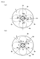
FIG. 3 is a cross-section plan view of the sleeve. -
FIG. 3(a) is a cross-section plan view of the sleeve in the case the directions of the nozzle holes are the same as the directions of theline 01. -
FIG. 3(b) is a cross-section plan view of the sleeve in the case the directions of the nozzle holes are the same as the directions of theline 02. -
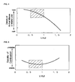
FIG. 4 is a graph showing the relation between the ratio of the height to the width of the auxiliary chamber (i.e. L1/L2) and the density of the air-fuel mixture in misfire limit. -
FIG. 5 is a graph showing the relation between the ratio of the height to the width of the auxiliary chamber (i.e. L1/L2) and the stability of combustion. -
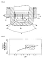
FIG. 6 is a cross-section view of the auxiliary chamber including the residual gas. -
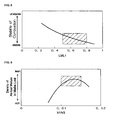
FIG. 7 is a graph showing the relation between the ratio of the length from the top of the auxiliary chamber to the position of ignition to the height of the auxiliary chamber (i.e. L3/L1) and the density of the air-fuel mixture in misfire limit. -
FIG. 8 is a graph showing the relation between the ratio of the length from the top of the auxiliary chamber to the position of ignition to the height of the auxiliary chamber (i.e. L3/L1) and the stability of combustion. -
FIG. 9 is a graph showing the relation between the ratio of the volume of the auxiliary chamber to that of the combustion chamber (i.e. V1/V2) and the density of the air-fuel mixture in misfire limit. -
FIG. 10 is a graph showing the relation between the ratio of the volume of the auxiliary chamber to that of the combustion chamber (i.e. V1/V2) and the stability of combustion. -
FIG. 11 is a graph showing the relation between the angles of the nozzle holes (i.e. the angle α) and the density of the air-fuel mixture in misfire limit. -
FIG. 12 is a graph showing the relation between the angles of the nozzle holes (i.e. the angle α) and the stability of combustion. -
FIG. 13 is a graph showing the relation between the direction of the nozzle holes (i.e. the angle β) and the density of the air-fuel mixture in misfire limit. -
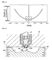
FIG. 14 is a graph showing the relation between the direction of the nozzle holes (i.e. the angle β) and the stability of combustion. -
FIG. 15 is a cross-section view of the conventional combustion chamber comprising the auxiliary chamber type ignition plug. -
FIG. 16 is an enlarged cross-section view of the conventional auxiliary chamber. -
- 1
- cylinder head
- 2
- cylinder
- 5
- combustion chamber
- 6
- sleeve
- 7
- ignition plug
- 7a
- ignition electrode (ground electrode)
- 7b
- ignition electrode (center electrode)
- 10
- auxiliary chamber
- 12
- position of ignition
- The best mode for carrying out the present invention will be described below.
-
-
FIG. 1 is a cross-section view of a combustion chamber, an ignition plug and a sleeve according to an embodiment of the present invention. -
FIG. 2 is a cross-section view of the ignition plug and an auxiliary chamber formed in the sleeve. -
FIG. 3 is a cross-section plan view of the sleeve. -
FIG. 3(a) is a cross-section plan view of the sleeve in the case the directions of the nozzle holes are the same as the directions of the line O1. -
FIG. 3(b) is a cross-section plan view of the sleeve in the case the directions of the nozzle holes are the same as the directions of theline 02. -
FIG. 4 is a graph showing the relation between the ratio of the height to the width of the auxiliary chamber (i.e. L1/L2) and the density of the air-fuel mixture in misfire limit. -
FIG. 5 is a graph showing the relation between the ratio of the height to the width of the auxiliary chamber (i.e. L1/L2) and the stability of combustion. -
FIG. 6 is a cross-section view of the auxiliary chamber including the residual gas. -
FIG. 7 is a graph showing the relation between the ratio of the length from the top of the auxiliary chamber to the position of ignition to the height of the auxiliary chamber (i.e. L3/L1) and the density of the air-fuel mixture in misfire limit. -
FIG. 8 is a graph showing the relation between the ratio of the length from the top of the auxiliary chamber to the position of ignition to the height of the auxiliary chamber (i.e. L3/L1) and the stability of combustion. -
FIG. 9 is a graph showing the relation between the ratio of the volume of the auxiliary chamber to that of the combustion chamber (i.e. V1/V2) and the density of the air-fuel mixture in misfire limit. -
FIG 10 is a graph showing the relation between the ratio of the volume of the auxiliary chamber to that of the combustion chamber (i.e. V1/V2) and the stability of combustion. -
FIG. 11 is a graph showing the relation between the angles of the nozzle holes (i.e. the angle α) and the density of the air-fuel mixture in misfire limit. -
FIG. 12 is a graph showing the relation between the angles of the nozzle holes (i.e. the angle α) and the stability of combustion. -
FIG. 13 is a graph showing the relation between the direction of the nozzle holes (i.e. the angle β) and the density of the air-fuel mixture in misfire limit. -
FIG. 14 is a graph showing the relation between the direction of the nozzle holes (i.e. the angle β) and the stability of combustion. -
FIG. 15 is a cross-section view of the conventional combustion chamber comprising the auxiliary chamber type ignition plug. -
FIG. 16 is an enlarged cross-section view of the conventional auxiliary chamber. - In the spark ignition engine according to the present invention, as shown in
FIGS. 1 and 2 , acylinder 2 is disposed under acylinder head 1 and apiston 3 is slidably installed in thecylinder 2 in the vertical direction. A concave-shapedsurface 3a is formed at the upper end of thepiston 3, facing thecylinder head 1. Acombustion chamber 5 is formed as the space surrounded by thecylinder head 1, thecylinder 2 and the concave-shapedsurface 3a. An intake valve and an exhaust valve (both not shown) are provided in thecylinder head 1, facingrespective valve recesses 3b provided on the piston 3(seeFIG. 3 ). Opening and shutting the intake valve and the exhaust valve alternately, the intake and exhaust for thecombustion chamber 5 can be carried out. - A
sleeve 6, which is formed in the blind cylindrical shape, is fitted in the vertical direction at the center of thecylinder head 1 related to thecombustion chamber 5. Anignition plug 7 is provided in thesleeve 6. Ignition electrodes (a ground electrode) 7a and (a center electrode) 7b are provided at the lower tip of theignition plug 7 so as to dispose over thecombustion chamber 5. Theignition electrodes sleeve 6 projected into thecombustion chamber 5. Thus, anauxiliary chamber 10 storing theignition electrodes sleeve 6. - As shown in
FIG. 3 , theauxiliary chamber 10 is disposed at the center of thecombustion chamber 5 viewed from the top and thevalve recesses 3b provided on thepiston 3 are disposed around theauxiliary chamber 10. The valve recesses 3b serve as a valve recess for the intake valve or for the exhaust valve. In this embodiment, fourvalve recesses 3b (the two of them are for the intake valve and the remainder for the exhaust valve) are disposed laterally symmetrically related to theauxiliary chamber 10 and arranged every 90 degrees. -
Plural nozzle holes 6a are drilled at the lower periphery of thesleeve 6 at equal intervals and thus theauxiliary chamber 10 is communicated with thecombustion chamber 5 through theplural nozzle holes 6a. Thus, the air-fuel mixture taken into thecylinder 2 by the intake valve flows into theauxiliary chamber 10 through theplural nozzle holes 6a, and then the air-fuel mixture is spark-ignited by theignition electrodes ignition plug 7. Hence, the flame is blown into thecombustion chamber 5 out of theplural nozzle holes 6a and transmitted. - Here, the bottom part of the
sleeve 6 provided with theplural nozzle holes 6a is projected into thecombustion chamber 5 and extended lower than anexplosion surface 1a (the bottom surface of thecylinder head 1 facing the cylinder 2). In thesleeve 6, theignition electrodes ignition plug 7 are projected near theexplosion surface 1a. Hence, theposition 12 of ignition by theignition electrodes auxiliary chamber 10 is set near theexplosion surface 1a in the vertical direction. - Consequently, when the air-fuel mixture in the
auxiliary chamber 10 is spark-ignited by theignition plug 7 in order to achieve the lean burn without another fuel supply, the flame jet can be generated by the flame blown into thecombustion chamber 5 out of theauxiliary chamber 10 through theplural nozzle holes 6a provided in thesleeve 6, so that the flame jet can generate the turbulence, which makes rapid combustion possible without the conventional auxiliary chamber type ignition plug. Moreover, theplural nozzle holes 6a can be provided away from theexplosion surface 1a, so that the flame jet can prevent from being affected by the temperature of theexplosion surface 1a. - Furthermore, the
auxiliary chamber 10 is configured as the space formed between thesleeve 6 and theignition plug 7, so that the shape thereof is obviously decided. Thus, theauxiliary chamber 10 can be simply formed, so that theauxiliary chamber 10 that is capable of preventing from being affected by the residual gas can be easily formed. - In this embodiment, the
auxiliary chamber 10 is formed in the cylindrical shape and the diameter thereof substantially corresponds to the outside diameter of thesleeve 6. As shown inFIG. 2 , the height (vertical length) of theauxiliary chamber 10 is defined as a length L1, which is the length from the inside bottom of thesleeve 6 to the bottom of theignition plug 7 and the diameter (lateral length) of theauxiliary chamber 10 is defined as a length L2, which is equal to the inside diameter of thesleeve 6. Theauxiliary chamber 10 is formed in such a way that the relation between the lengths L1 and L2 implements a formula (1).
auxiliary chamber 10 is calculated by dividing the height of theauxiliary chamber 10 by the diameter of theauxiliary chamber 10 and the ratio L1/L2 of theauxiliary chamber 10 is set within the range of 0.5 to 1.0, namely, theauxiliary chamber 10 is formed with the longer side at the top thereof in a cross-section view. - As shown in
FIG. 4 , theauxiliary chamber 10 is formed as described above, so that the density of the air-fuel mixture in misfire limit when the ratio L1/L2 is small can be leaner than when the ratio is large. In other words, the excess air ratio in misfire limit becomes larger. Thus, the ratio of theauxiliary chamber 10 is set as an appropriate value within the above-mentioned range, so that the engine can be operated with as lean air-fuel mixture as possible. - As shown in
FIG. 5 , if the ratio L1/L2 of theauxiliary chamber 10 is set within the range of 0.5 to 1.0, then the variation ratio in combustion can become the smallest and the stability of combustion can be increased. Therefore, the stable combustion can be achieved with lean air-fuel mixture, and thus the high-compression operation can be achieved. - If the position of ignition by the ignition electrodes in the auxiliary chamber is conventionally set at the upper part of the auxiliary chamber, namely, at the opposite side to the nozzle holes communicating to the combustion chamber, then much residual gas exists around the position of ignition in the auxiliary chamber before the piston reaches top dead center. Thus, when new air-fuel mixture is flowed into the auxiliary chamber through the nozzle holes, the new air-fuel mixture cannot efficiently reach the position of ignition, affected by the residual gas, and when spark-ignited the stable combustion cannot be achieved.
- In order to secure stable ignition and combustion performance with the lean air-fuel mixture, the
position 12 of ignition is set at the appropriate position where the residual gas may not affect. As shown inFIG. 6 , in theauxiliary chamber 10 set at the appropriate ratio above-mentioned, theignition electrodes ignition plug 7 are projected into theauxiliary chamber 10 and theposition 12 of ignition by theignition electrodes sleeve 6 and near theexplosion surface 1a. - The
position 12 of ignition by theignition electrodes auxiliary chamber 10 at the ignition timing before thepiston 3 reaches top dead center during the compression stroke is calculated. The volume that the calculated volume of the residual gas occupies in theauxiliary chamber 10 is set smaller than the predetermined one. In other words, the volume of the residual gas that is remaining in theauxiliary chamber 10 at the ignition timing before thepiston 3 reaches top dead center during the compression stroke is calculated according to a formula (2).
- The
position 12 of ignition is determined according to the volume of the space over theposition 12 of ignition in theauxiliary chamber 10, which is set larger than the volume of the residual gas calculated according to the formula (2). Here, when thepiston 3 is pushed up, the residual exhaust gas is compressed upward. The volume of the residual exhaust gas is set smaller than the volume of the space over theposition 12 of ignition in theauxiliary chamber 10, so that the residual exhaust gas can be positioned over the position of ignition when spark-ignited. Consequently, the combustion in theauxiliary chamber 10 can prevent from being affected. - The volume of the space over the
position 12 of ignition in theauxiliary chamber 10 can be calculated on the basis of a length L3 between the top of the auxiliary chamber (the bottom of the ignition plug 7) and theposition 12 of ignition and the length L2 (the diameter of the auxiliary chamber 10). Here, the bottom area is common. Therefore, the value calculated by dividing the volume of residual gas by the bottom area is set shorter than the length L3. - In other words, at the ignition timing before the
piston 3 reaches top dead center, if the position of ignition is set appropriately, then the length L3 between the top of theauxiliary chamber 10 and theposition 12 of ignition is set longer than a length L4 between the upper end of theauxiliary chamber 10 and the lower end of the residual gas existing in the auxiliary chamber 10 (i.e. L3>L4). - Thus, the
position 12 of ignition of the air-fuel mixture by theignition electrodes ignition plug 7 is set at nearer thenozzle holes 6a than the residual gas remained in theauxiliary chamber 10. Therefore, theposition 12 of ignition by theignition plug 7 can be set at the appropriate position in theauxiliary chamber 10, so that the ignition and combustion performance can prevent from being affected by the residual gas in theauxiliary chamber 10. Consequently, the stable ignition and combustion can be achieved even with the leaner air-fuel mixture, and thus the available operation range of the engine can be expanded to the lean side. - Concretely, the
position 12 of ignition is set against theauxiliary chamber 10 in such a way that the relation between the length L3 between the inside upper surface of theauxiliary chamber 10 and theposition 12 of ignition and the length L1 defined as the height of theauxiliary chamber 10 implements a formula (3).
- In this case, as shown in
FIG. 7 , the density of the air-fuel mixture in misfire limit when the calculated value L3/L1 is large can be leaner than when the value L3/L1 is small. In other words, the excess air ratio in misfire limit becomes larger. Thus, the calculated value L3/L1 is set as an appropriate value within the above-mentioned range and theposition 12 of ignition is set against theauxiliary chamber 10, so that the engine can be operated with as lean air-fuel mixture as possible. - As shown in
FIG. 8 , if the density of the air-fuel mixture in misfire limit is constant, then when the calculated value L3/L1 is large the stability of combustion can be increased and the variation ratio in combustion can become smaller than when the value L3/L1 is small. Therefore, the stable combustion can be achieved with lean air-fuel mixture, and thus the high-compression operation can be achieved. - A volume V1 is defined as the volume of the
auxiliary chamber 10 and a volume V2 is defined as the volume of thecombustion chamber 5 when thepiston 3 reaches top dead center. The relation between the volume V1 and V2 implements a formula (4).
- In the
auxiliary chamber 10, as shown inFIG. 9 , if the ratio V1/V2 is set within the range of 0.010 to 0.015, then the density of the air-fuel mixture becomes leanest in misfire limit. In other words, the excess air ratio in misfire limit becomes larger. Thus, the volume ratio of the auxiliary chamber to the combustion chamber is set as an appropriate value within the above-mentioned range, so that the engine can be operated with as lean air-fuel mixture as possible. - As shown in
FIG. 10 , if the ratio V1/V2 is set within the range of 0.010 to 0.015, then the variation ratio in combustion can become the smallest and the stability of combustion can be increased. Therefore, the stable combustion can be achieved with lean air-fuel mixture, and thus the high-compression operation can be achieved. - The
auxiliary chamber 10 is formed as above-mentioned, whereas theplural nozzle holes 6a are drilled at the bottom of thesleeve 6 in such a way that there are plural pairs of twonozzle holes 6a drilled in the diameter direction. That is to say, the plural pairs of twonozzle holes 6a are set symmetrically relative to theposition 12 of ignition by theignition plug 7. Moreover, thenozzle holes 6a are formed inclined downward toward the outer periphery of thecombustion chamber 5 and the flame jet can be blown radially into thecombustion chamber 5 out of theauxiliary chamber 10 through thenozzle holes 6a. Furthermore, as shown inFIG. 6 , the angle α that each of the pair ofnozzle holes 6a makes in the gravity direction is set within the range of 80 to 100 degrees. - As shown in
FIG.11 , if the angle α is set within the range of 80 to 100 degrees, then the density of the air-fuel mixture becomes leanest in misfire limit. In other words, the excess air ratio in misfire limit becomes larger. Thus, the angle α is set at the appropriate value within the above-mentioned range, so that the engine can be operated with as lean air-fuel mixture as possible. - As shown in
FIG. 12 , if the angle α is set within the range of 80 to 100 degrees, then the variation ratio in combustion can become smaller and the stability of combustion can be increased to the best. Therefore, the stable combustion can be achieved with lean air-fuel mixture, and thus the high-compression operation can be achieved. - Moreover, the pairs of
nozzle holes 6a are spaced at equal intervals related to theposition 12 of ignition by theignition plug 7 in a top view. In this embodiment, two pairs ofnozzle holes 6a are drilled and arranged every 90 degrees. In other words, four nozzle holes are drilled and arranged every 90 degrees at the bottom periphery of theauxiliary chamber 10. - The directions of drilling the nozzle holes are set in such a way that, as shown in
FIG. 3(a) , each of the blowout direction of the flame jet out of thenozzle hole 6a points the each center of thevalve recess 3b (the directions of the nozzle holes are the same as the directions of the line O1) In an alternative embodiment, as shown inFIG 3(b) , the directions of the nozzle holes are set in such a way that each of the blowout direction of the flame jet out of thenozzle hole 6a points the each center of the twoadjacent valve recesses 3b (the directions of the nozzle holes are the same as the directions of the line 02). - Moreover, a tolerance angle β that the drilling direction of the
nozzle hole 6a and the line O1 or O2 makes is set within the range of -10 to 10 degrees in the horizontal direction. Furthermore, the directions of drilling thenozzle holes 6a are determined whether the directions of the line O1 or O2 according to the shape of thecombustion chamber 5. Here, the arrows inFIG. 3(a) and 3(b) show the blowout directions of the flame jets blown off out of thenozzle holes 6a. - As shown in
FIG.13 , if the directions of drilling thenozzle holes 6a is set as the directions of the line O1 or O2 and the tolerance angle β is set within the range of -10 to 10 degrees in the horizontal direction, then the density of the air-fuel mixture becomes leanest in misfire limit. In other words, the excess air ratio in misfire limit becomes larger. Thus, the directions of drilling thenozzle holes 6a are set as the appropriate value within the above-mentioned range, so that the engine can be operated with as lean air-fuel mixture as possible. - As shown in
FIG. 14 , if the tolerance angle β is set within the range of -10 to 10 degrees, then the variation ratio in combustion can become smaller and the stability of combustion can be increased. Therefore, the stable combustion can be achieved with lean air-fuel mixture, and thus the high-compression operation can be achieved. - According to the present invention, the spark ignition engine can be suitably applicable to spark ignition engines comprising the single chamber type combustion chamber.
Claims (5)
- A spark ignition engine comprising:a cylinder (2);a cylinder head (1) disposed above the cylinder (2);a piston (3) disposed in the cylinder (2);a single chamber type combustion chamber (5) provided in the cylinder (2) above the piston (3), wherein the cylinder head (1) has a bottom surface facing the combustion chamber (5), the bottom surface of the cylinder head (1) being defined as an explosion surface (1a);a cylindrical sleeve (6) having a first bottom and a second bottom extended downward from the first bottom;an ignition plug (7) fitted to the cylinder head (1) through the sleeve (6);an auxiliary chamber (10) formed so as to be surrounded by the sleeve (6) and the ignition plug (7), wherein the auxiliary chamber (10) has a vertical length (L1) between an inside bottom of the second bottom of the sleeve (6) and a bottom of the ignition plug (7) fitted in the sleeve (6), and the auxiliary chamber (10) has a diameter (L2), which is equal to the inside diameter of the sleeve (6);a set of ignition electrodes (7a,7b) of the ignition plug (7) disposed in the auxiliary chamber (10) so as to face the combustion chamber (5) in the cylinder (2); andone or more nozzle holes (6a) allowing the auxiliary chamber (10) to communicate with the combustion chamber (5),wherein the second bottom of the sleeve (6) serving as the bottom of the auxiliary chamber (10) is projected to the inside of the combustion chamber (5) from the explosion surface (1a) of the cylinder head (1) so as to locate an ignition position (12) for ignition by the ignition electrodes (7a,7b) at a height that is substantially equal to a height of the explosion surface (1a),characterized in that the set of ignition electrodes (7a,7b) of the ignition plug (7) in the auxiliary chamber (10) and, therefore, the ignition position (12) is located at a distance (L3) to the top of auxiliary chamber (10) so that a volume of a space between the ignition position (12) and the upper end of the auxiliary chamber (10) is calculated on the basis of the length (L3) and the diameter (L2) and said volume of space is larger than a volume of residual gas remaining in the auxiliary chamber (10) at an ignition timing before the piston (3) reaches a top dead center during its compression stroke, whereby said volume of residual gas remaining in the auxiliary chamber (10) is calculated by multiplying a volume (V1) of the auxiliary chamber (10) by a ratio of a volume of the cylinder (2) including the volume (V1) of the auxiliary chamber (10) at the ignition timing to a volume of the cylinder (2) including the volume (V1) of the auxiliary chamber (10) when an intake valve is closed, and when said calculated volume of residual gas remaining in the auxiliary chamber (10) is compressed upward in the auxiliary chamber (10), a length (L4) between the upper end of the auxiliary chamber (10) and the lower end of the residual gas existing in the auxiliary chamber (10) is smaller than the length (L3), thereby setting the ignition position (12) lower than the residual gas remaining in the auxiliary chamber (10) at the ignition timing, whereby a ratio of a length (L3) between an inside upper surface of the auxiliary chamber (10) defined by the bottom of the ignition plug (7) and the ignition position (12) to the vertical length (L1) of the auxiliary chamber (10) is set within a range of 0.5 to 0.8.
- The spark ignition engine according to claim 1, wherein the auxiliary chamber (10) surrounded by the sleeve (6) and the ignition plug (7) is formed in a cylindrical shape having a horizontal diameter (L2), and wherein a ratio of the vertical length (L1) of the auxiliary chamber (10) to the diameter (L2) thereof is set within a range of 0.5 to 1.0.
- The spark ignition engine according to claim 1 or 2, wherein a ratio of a volume (V1) of the auxiliary chamber (10) to a volume (V2) of the combustion chamber (5) when the piston (3) reaches the top dead center is set within a range of 0.010 to 0.015.
- The spark ignition engine according to any one of claim 1 to 3, wherein the nozzle holes (6a) are set as one or more pairs of the nozzle holes (6a) symmetrical relative to the ignition position (12) in the gravity direction and wherein an angle between the nozzle holes (6a) of each pair is set within a range (α) of 80 to 100 degrees.
- The spark ignition engine according to any one of claim 1 to 3, wherein valve recesses (3b) are formed on the piston (3) at an outer peripheral area of the combustion chamber (5), wherein each of the nozzle holes (6a) is directed in the horizontal direction within a tolerance angle range (β) of -10 to 10 degrees from either a line (O1) passed on a center of each of the valve recesses (3b) or a line (02) passed between each pair of neighboring valve recesses (3b).
Applications Claiming Priority (2)
| Application Number | Priority Date | Filing Date | Title |
|---|---|---|---|
| JP2005268090A JP4473802B2 (en) | 2005-09-15 | 2005-09-15 | Spark ignition engine |
| PCT/JP2006/317070 WO2007032206A1 (en) | 2005-09-15 | 2006-08-30 | Spark ignition engine |
Publications (3)
| Publication Number | Publication Date |
|---|---|
| EP1936144A1 EP1936144A1 (en) | 2008-06-25 |
| EP1936144A4 EP1936144A4 (en) | 2009-05-13 |
| EP1936144B1 true EP1936144B1 (en) | 2010-10-13 |
Family
ID=37864804
Family Applications (1)
| Application Number | Title | Priority Date | Filing Date |
|---|---|---|---|
| EP06797044A Not-in-force EP1936144B1 (en) | 2005-09-15 | 2006-08-30 | Spark ignition engine |
Country Status (8)
| Country | Link |
|---|---|
| US (1) | US7856956B2 (en) |
| EP (1) | EP1936144B1 (en) |
| JP (1) | JP4473802B2 (en) |
| KR (1) | KR100969738B1 (en) |
| CN (1) | CN101243245B (en) |
| DE (1) | DE602006017573D1 (en) |
| ES (1) | ES2354050T3 (en) |
| WO (1) | WO2007032206A1 (en) |
Families Citing this family (46)
| Publication number | Priority date | Publication date | Assignee | Title |
|---|---|---|---|---|
| JP5085419B2 (en) * | 2008-05-09 | 2012-11-28 | 大阪瓦斯株式会社 | Engine and spark plug for engine |
| JP5122367B2 (en) * | 2008-05-09 | 2013-01-16 | 大阪瓦斯株式会社 | Engine and spark plug for engine |
| JP5060386B2 (en) * | 2008-05-09 | 2012-10-31 | 大阪瓦斯株式会社 | engine |
| JP5002566B2 (en) * | 2008-10-16 | 2012-08-15 | 大阪瓦斯株式会社 | Engine and spark plug for engine |
| JP5426998B2 (en) * | 2009-11-06 | 2014-02-26 | 大阪瓦斯株式会社 | Spark plug and engine equipped with the spark plug |
| DE102009047021A1 (en) * | 2009-11-23 | 2011-05-26 | Robert Bosch Gmbh | laser spark plug |
| DE102009047019A1 (en) * | 2009-11-23 | 2011-05-26 | Robert Bosch Gmbh | laser spark plug |
| EP2525452B1 (en) * | 2010-01-15 | 2020-05-13 | NGK Sparkplug Co., Ltd. | Spark plug and method of manufacturing spark plug |
| JP5451490B2 (en) | 2010-03-31 | 2014-03-26 | 株式会社デンソー | Spark plug and engine |
| DE102010003899A1 (en) * | 2010-04-13 | 2011-10-13 | Robert Bosch Gmbh | Laser spark plug with an antechamber |
| US9353674B2 (en) * | 2010-11-01 | 2016-05-31 | Mahle Powertrain, Llc | Turbulent jet ignition pre-chamber combustion system for spark ignition engines |
| US9476347B2 (en) | 2010-11-23 | 2016-10-25 | Woodward, Inc. | Controlled spark ignited flame kernel flow in fuel-fed prechambers |
| US9172217B2 (en) | 2010-11-23 | 2015-10-27 | Woodward, Inc. | Pre-chamber spark plug with tubular electrode and method of manufacturing same |
| US8584648B2 (en) | 2010-11-23 | 2013-11-19 | Woodward, Inc. | Controlled spark ignited flame kernel flow |
| JP2014502692A (en) * | 2010-12-31 | 2014-02-03 | プロメテウス アプライド テクノロジーズ,エルエルシー | Pre-chamber ignition device |
| RU2535308C2 (en) | 2012-04-20 | 2014-12-10 | Константин Иванович Федин | Method of operation for gas piston engine with spark ignition |
| US9856848B2 (en) | 2013-01-08 | 2018-01-02 | Woodward, Inc. | Quiescent chamber hot gas igniter |
| JP6030473B2 (en) * | 2013-02-20 | 2016-11-24 | 日本特殊陶業株式会社 | Spark plug and engine |
| US8839762B1 (en) | 2013-06-10 | 2014-09-23 | Woodward, Inc. | Multi-chamber igniter |
| US9765682B2 (en) | 2013-06-10 | 2017-09-19 | Woodward, Inc. | Multi-chamber igniter |
| CN103399036A (en) * | 2013-08-22 | 2013-11-20 | 天津出入境检验检疫局工业产品安全技术中心 | Ignition device of solid dangerous goods pressure test equipment |
| DE102014117714B4 (en) * | 2014-12-02 | 2016-06-09 | Federal-Mogul Ignition Gmbh | Spark plug for a gas-powered internal combustion engine |
| JP6580701B2 (en) | 2015-03-20 | 2019-09-25 | ウッドワード, インコーポレーテッドWoodward, Inc. | Parallel pre-combustion chamber ignition system |
| US9653886B2 (en) | 2015-03-20 | 2017-05-16 | Woodward, Inc. | Cap shielded ignition system |
| CN108026827B (en) * | 2015-06-30 | 2019-12-31 | 康明斯公司 | Nozzle Combustion Guard |
| CN108779702A (en) * | 2015-10-08 | 2018-11-09 | 康明斯公司 | Pre-chamber components |
| US10066580B2 (en) * | 2015-10-15 | 2018-09-04 | The Regents Of The University Of Michigan | Lean burn internal combustion engine |
| US9890689B2 (en) | 2015-10-29 | 2018-02-13 | Woodward, Inc. | Gaseous fuel combustion |
| JP2017103179A (en) * | 2015-12-04 | 2017-06-08 | 株式会社デンソー | Spark plug |
| JP6556037B2 (en) * | 2015-12-04 | 2019-08-07 | 株式会社デンソー | Internal combustion engine and spark plug |
| JP6674268B2 (en) * | 2016-02-04 | 2020-04-01 | 本田技研工業株式会社 | Gas engine |
| JP6919558B2 (en) * | 2017-12-27 | 2021-08-18 | トヨタ自動車株式会社 | Internal combustion engine |
| JP2019206960A (en) * | 2018-05-30 | 2019-12-05 | 株式会社Soken | Internal combustion engine |
| JP7095570B2 (en) * | 2018-11-26 | 2022-07-05 | トヨタ自動車株式会社 | Internal combustion engine with sub-chamber |
| JP7260331B2 (en) * | 2019-02-27 | 2023-04-18 | ダイハツ工業株式会社 | Internal combustion engine with auxiliary combustion chamber |
| JP7143936B2 (en) * | 2019-03-27 | 2022-09-29 | 三菱自動車工業株式会社 | pre-chamber internal combustion engine |
| JP7365790B2 (en) * | 2019-05-20 | 2023-10-20 | 株式会社デンソー | Internal combustion engine and spark plug |
| US11415041B2 (en) * | 2019-09-16 | 2022-08-16 | Woodward, Inc. | Flame triggered and controlled volumetric ignition |
| US11840954B2 (en) | 2020-02-24 | 2023-12-12 | Mahle International Gmbh | Spark ignited engine with a pre-chamber, a prechamber and an adapter insert for the engine |
| US11280278B2 (en) * | 2020-07-06 | 2022-03-22 | Ford Global Technologies, Llc | Methods and systems for a series gap igniter with a passive pre-chamber |
| CN113969825B (en) * | 2020-07-23 | 2022-12-20 | 广州汽车集团股份有限公司 | Split type precombustion chamber |
| JP7653233B2 (en) * | 2020-09-03 | 2025-03-28 | 株式会社Soken | Spark plugs for internal combustion engines |
| JP7426511B2 (en) * | 2022-02-15 | 2024-02-01 | ヤマハ発動機株式会社 | Pre-chamber combustion 4-stroke engine |
| US12565849B2 (en) * | 2022-10-27 | 2026-03-03 | Saudi Arabian Oil Company | Spray guided stratification for fueling a passive pre-chamber |
| DE102024211729A1 (en) * | 2024-12-09 | 2026-06-11 | Robert Bosch Gesellschaft mit beschränkter Haftung | Method for operating an internal combustion engine with hydrogen and a pre-chamber spark plug for igniting an air-hydrogen mixture in a combustion chamber |
| GB2703459A (en) * | 2024-12-18 | 2026-07-29 | Jcb Res | An internal combustion engine |
Family Cites Families (26)
| Publication number | Priority date | Publication date | Assignee | Title |
|---|---|---|---|---|
| GB478929A (en) * | 1937-04-30 | 1938-01-27 | Maurice Delattre | Improvements in sparking plugs for internal combustion engines |
| JPS5642115B2 (en) * | 1973-11-01 | 1981-10-02 | ||
| JPS5830135B2 (en) * | 1974-04-02 | 1983-06-27 | 古河電気工業株式会社 | Plastic Hatsupoutai no Osidashi Seikeihou |
| CA1047250A (en) | 1974-06-13 | 1979-01-30 | James F. Scott | Fuel compositions useful for gas turbines and process for the combustion of such fuel compositions |
| JPS5112803U (en) * | 1974-07-17 | 1976-01-30 | ||
| JPS5157313A (en) * | 1974-11-13 | 1976-05-19 | Toyota Motor Co Ltd | Nainenkikanno nokongokino kyokyusochi |
| JPS5642115A (en) | 1979-09-17 | 1981-04-20 | Fujitsu Ltd | Measuring method for diameter of beam |
| JPS5766224A (en) | 1980-10-02 | 1982-04-22 | Shimizu Constr Co Ltd | In-situ concrete pile construction |
| JPS5766224U (en) * | 1980-10-07 | 1982-04-20 | ||
| JPS6081227U (en) * | 1983-11-09 | 1985-06-05 | 日産自動車株式会社 | Combustion chamber of spark-ignited internal combustion engine |
| JPS6415862A (en) | 1987-07-10 | 1989-01-19 | Mitsubishi Electric Corp | Multi-processor schedule system |
| CN2054218U (en) * | 1989-02-11 | 1990-03-07 | 张积俭 | Spark plug with precombustion chamber |
| US5105780A (en) * | 1990-08-08 | 1992-04-21 | Caterpillar Inc. | Ignition assisting device for internal combustion engines |
| JPH04287826A (en) * | 1991-03-19 | 1992-10-13 | Nissan Motor Co Ltd | Spark ignition internal combustion engine of auxiliary chamber |
| US5224449A (en) * | 1991-10-31 | 1993-07-06 | Osaka Gas Company, Ltd. | Lean-burn internal combustion system |
| EP0675272B1 (en) | 1994-03-29 | 1997-08-06 | Dieter Dr. Kuhnert | Prechamber ignition device |
| US6188966B1 (en) | 1998-02-10 | 2001-02-13 | Agilent Technologies | Reconstruction of multi-phase signals from repetitive samples |
| JPH11280628A (en) | 1998-03-26 | 1999-10-15 | Toyota Motor Corp | Ignition timing control device for internal combustion engine |
| US5947076A (en) * | 1998-04-17 | 1999-09-07 | Caterpillar Inc. | Fuel combustion assembly for an internal combustion engine having an encapsulated spark plug for igniting lean gaseous fuel within a precombustion chamber |
| DE10144976A1 (en) * | 2001-09-12 | 2003-04-03 | Beru Ag | Ignition plug includes electrode on central axis within ante-chamber, and has air gap to earth electrode rather than chamber wall |
| JP2003278547A (en) * | 2002-03-25 | 2003-10-02 | Tokyo Gas Co Ltd | Subchamber engine |
| FR2846042B1 (en) * | 2002-10-18 | 2005-02-04 | Peugeot Citroen Automobiles Sa | PRE-BRAKE IGNITION DEVICE MADE IN HIGH THERMAL CONDUCTIVITY MATERIAL FOR INTERNAL COMBUSTION ENGINE AND PRE-BURST IGNITER |
| FR2846044B1 (en) | 2002-10-18 | 2006-07-14 | Peugeot Citroen Automobiles Sa | PRECHAMBRE IGNITION DEVICE COATED WITH A REFRACTORY COATING, FOR AN INTERNAL COMBUSTION ENGINE, AND PRE-CHAMBER IGNITER |
| FR2846046B1 (en) * | 2002-10-18 | 2006-06-16 | Peugeot Citroen Automobiles Sa | PRE-CHAMBER IGNITION DEVICE FOR INTERNAL COMBUSTION ENGINE, PRE-CHAMBER IGNITER, AND IGNITION METHOD |
| JP2004204835A (en) | 2002-10-28 | 2004-07-22 | Toyota Motor Corp | Spark ignition internal combustion engine |
| JP4287826B2 (en) | 2005-02-14 | 2009-07-01 | Tdk株式会社 | Capacitor and manufacturing method thereof, filter using the same, and dielectric thin film used therefor |
-
2005
- 2005-09-15 JP JP2005268090A patent/JP4473802B2/en not_active Expired - Fee Related
-
2006
- 2006-08-30 DE DE602006017573T patent/DE602006017573D1/en active Active
- 2006-08-30 WO PCT/JP2006/317070 patent/WO2007032206A1/en not_active Ceased
- 2006-08-30 CN CN2006800304405A patent/CN101243245B/en not_active Expired - Fee Related
- 2006-08-30 KR KR1020087008112A patent/KR100969738B1/en not_active Expired - Fee Related
- 2006-08-30 ES ES06797044T patent/ES2354050T3/en active Active
- 2006-08-30 EP EP06797044A patent/EP1936144B1/en not_active Not-in-force
- 2006-08-30 US US12/066,942 patent/US7856956B2/en not_active Expired - Fee Related
Also Published As
| Publication number | Publication date |
|---|---|
| WO2007032206A1 (en) | 2007-03-22 |
| US7856956B2 (en) | 2010-12-28 |
| EP1936144A1 (en) | 2008-06-25 |
| JP4473802B2 (en) | 2010-06-02 |
| DE602006017573D1 (en) | 2010-11-25 |
| ES2354050T3 (en) | 2011-03-09 |
| CN101243245B (en) | 2011-04-27 |
| US20090133667A1 (en) | 2009-05-28 |
| JP2007077902A (en) | 2007-03-29 |
| CN101243245A (en) | 2008-08-13 |
| EP1936144A4 (en) | 2009-05-13 |
| KR100969738B1 (en) | 2010-07-13 |
| KR20080042169A (en) | 2008-05-14 |
Similar Documents
| Publication | Publication Date | Title |
|---|---|---|
| US7856956B2 (en) | Spark ignition engine | |
| US8350457B2 (en) | Pre-chamber spark plug including a gas thread cavity | |
| CN111164285B (en) | Internal combustion engine for a motor vehicle | |
| EP3271561B1 (en) | Parallel prechamber ignition system | |
| CN104508276B (en) | Secondary chamber gas engine | |
| EP3536924B1 (en) | Precombustion chamber gas engine | |
| CN111219241B (en) | Internal combustion engine with auxiliary chamber | |
| JP7388224B2 (en) | Internal combustion engine with prechamber | |
| US10012134B2 (en) | Internal combustion engine | |
| JP2007040174A (en) | Sub-chamber internal combustion engine | |
| KR20230035606A (en) | Prechamber spark plug and internal combustion engine with optimized cap | |
| US7741762B2 (en) | Dual-spark pre-chambered spark igniter | |
| JP7673220B2 (en) | Internal combustion engine having spark plug and pre-chamber spark plug | |
| WO2018110326A1 (en) | Sub-chamber gas engine | |
| JP5122367B2 (en) | Engine and spark plug for engine | |
| JP7756999B2 (en) | internal combustion engine | |
| US7066137B1 (en) | Anti detonation device and method for internal combustion engines | |
| JP2007297942A (en) | Ignition device for internal combustion engine | |
| JP2007291934A (en) | Multi-hole injector | |
| JP5564538B2 (en) | Engine combustion chamber structure | |
| JP2022069418A (en) | A spark plug for an internal combustion engine and an internal combustion engine equipped with this | |
| US12116952B1 (en) | Internal combustion engine and combustion chamber for an internal combustion engine | |
| JP2021038715A (en) | Internal combustion engine with sub-combustion chamber | |
| JP4457999B2 (en) | In-cylinder internal combustion engine | |
| JP5178491B2 (en) | Engine combustion chamber structure |
Legal Events
| Date | Code | Title | Description |
|---|---|---|---|
| PUAI | Public reference made under article 153(3) epc to a published international application that has entered the european phase |
Free format text: ORIGINAL CODE: 0009012 |
|
| 17P | Request for examination filed |
Effective date: 20080225 |
|
| AK | Designated contracting states |
Kind code of ref document: A1 Designated state(s): AT BE BG CH CY CZ DE DK EE ES FI FR GB GR HU IE IS IT LI LT LU LV MC NL PL PT RO SE SI SK TR |
|
| A4 | Supplementary search report drawn up and despatched |
Effective date: 20090409 |
|
| 17Q | First examination report despatched |
Effective date: 20090728 |
|
| GRAP | Despatch of communication of intention to grant a patent |
Free format text: ORIGINAL CODE: EPIDOSNIGR1 |
|
| GRAS | Grant fee paid |
Free format text: ORIGINAL CODE: EPIDOSNIGR3 |
|
| GRAA | (expected) grant |
Free format text: ORIGINAL CODE: 0009210 |
|
| AK | Designated contracting states |
Kind code of ref document: B1 Designated state(s): AT BE BG CH CY CZ DE DK EE ES FI FR GB GR HU IE IS IT LI LT LU LV MC NL PL PT RO SE SI SK TR |
|
| REG | Reference to a national code |
Ref country code: GB Ref legal event code: FG4D |
|
| REG | Reference to a national code |
Ref country code: CH Ref legal event code: EP |
|
| REG | Reference to a national code |
Ref country code: IE Ref legal event code: FG4D |
|
| REF | Corresponds to: |
Ref document number: 602006017573 Country of ref document: DE Date of ref document: 20101125 Kind code of ref document: P |
|
| REG | Reference to a national code |
Ref country code: NL Ref legal event code: VDEP Effective date: 20101013 |
|
| REG | Reference to a national code |
Ref country code: ES Ref legal event code: FG2A Effective date: 20110225 |
|
| LTIE | Lt: invalidation of european patent or patent extension |
Effective date: 20101013 |
|
| PG25 | Lapsed in a contracting state [announced via postgrant information from national office to epo] |
Ref country code: LT Free format text: LAPSE BECAUSE OF FAILURE TO SUBMIT A TRANSLATION OF THE DESCRIPTION OR TO PAY THE FEE WITHIN THE PRESCRIBED TIME-LIMIT Effective date: 20101013 |
|
| PG25 | Lapsed in a contracting state [announced via postgrant information from national office to epo] |
Ref country code: IS Free format text: LAPSE BECAUSE OF FAILURE TO SUBMIT A TRANSLATION OF THE DESCRIPTION OR TO PAY THE FEE WITHIN THE PRESCRIBED TIME-LIMIT Effective date: 20110213 Ref country code: PT Free format text: LAPSE BECAUSE OF FAILURE TO SUBMIT A TRANSLATION OF THE DESCRIPTION OR TO PAY THE FEE WITHIN THE PRESCRIBED TIME-LIMIT Effective date: 20110214 Ref country code: SE Free format text: LAPSE BECAUSE OF FAILURE TO SUBMIT A TRANSLATION OF THE DESCRIPTION OR TO PAY THE FEE WITHIN THE PRESCRIBED TIME-LIMIT Effective date: 20101013 Ref country code: LV Free format text: LAPSE BECAUSE OF FAILURE TO SUBMIT A TRANSLATION OF THE DESCRIPTION OR TO PAY THE FEE WITHIN THE PRESCRIBED TIME-LIMIT Effective date: 20101013 Ref country code: NL Free format text: LAPSE BECAUSE OF FAILURE TO SUBMIT A TRANSLATION OF THE DESCRIPTION OR TO PAY THE FEE WITHIN THE PRESCRIBED TIME-LIMIT Effective date: 20101013 Ref country code: BG Free format text: LAPSE BECAUSE OF FAILURE TO SUBMIT A TRANSLATION OF THE DESCRIPTION OR TO PAY THE FEE WITHIN THE PRESCRIBED TIME-LIMIT Effective date: 20110113 Ref country code: SI Free format text: LAPSE BECAUSE OF FAILURE TO SUBMIT A TRANSLATION OF THE DESCRIPTION OR TO PAY THE FEE WITHIN THE PRESCRIBED TIME-LIMIT Effective date: 20101013 |
|
| PG25 | Lapsed in a contracting state [announced via postgrant information from national office to epo] |
Ref country code: GR Free format text: LAPSE BECAUSE OF FAILURE TO SUBMIT A TRANSLATION OF THE DESCRIPTION OR TO PAY THE FEE WITHIN THE PRESCRIBED TIME-LIMIT Effective date: 20110114 Ref country code: BE Free format text: LAPSE BECAUSE OF FAILURE TO SUBMIT A TRANSLATION OF THE DESCRIPTION OR TO PAY THE FEE WITHIN THE PRESCRIBED TIME-LIMIT Effective date: 20101013 |
|
| PG25 | Lapsed in a contracting state [announced via postgrant information from national office to epo] |
Ref country code: CZ Free format text: LAPSE BECAUSE OF FAILURE TO SUBMIT A TRANSLATION OF THE DESCRIPTION OR TO PAY THE FEE WITHIN THE PRESCRIBED TIME-LIMIT Effective date: 20101013 Ref country code: EE Free format text: LAPSE BECAUSE OF FAILURE TO SUBMIT A TRANSLATION OF THE DESCRIPTION OR TO PAY THE FEE WITHIN THE PRESCRIBED TIME-LIMIT Effective date: 20101013 |
|
| PLBE | No opposition filed within time limit |
Free format text: ORIGINAL CODE: 0009261 |
|
| STAA | Information on the status of an ep patent application or granted ep patent |
Free format text: STATUS: NO OPPOSITION FILED WITHIN TIME LIMIT |
|
| PG25 | Lapsed in a contracting state [announced via postgrant information from national office to epo] |
Ref country code: PL Free format text: LAPSE BECAUSE OF FAILURE TO SUBMIT A TRANSLATION OF THE DESCRIPTION OR TO PAY THE FEE WITHIN THE PRESCRIBED TIME-LIMIT Effective date: 20101013 Ref country code: RO Free format text: LAPSE BECAUSE OF FAILURE TO SUBMIT A TRANSLATION OF THE DESCRIPTION OR TO PAY THE FEE WITHIN THE PRESCRIBED TIME-LIMIT Effective date: 20101013 Ref country code: DK Free format text: LAPSE BECAUSE OF FAILURE TO SUBMIT A TRANSLATION OF THE DESCRIPTION OR TO PAY THE FEE WITHIN THE PRESCRIBED TIME-LIMIT Effective date: 20101013 Ref country code: SK Free format text: LAPSE BECAUSE OF FAILURE TO SUBMIT A TRANSLATION OF THE DESCRIPTION OR TO PAY THE FEE WITHIN THE PRESCRIBED TIME-LIMIT Effective date: 20101013 |
|
| 26N | No opposition filed |
Effective date: 20110714 |
|
| REG | Reference to a national code |
Ref country code: DE Ref legal event code: R097 Ref document number: 602006017573 Country of ref document: DE Effective date: 20110714 |
|
| PG25 | Lapsed in a contracting state [announced via postgrant information from national office to epo] |
Ref country code: IT Free format text: LAPSE BECAUSE OF FAILURE TO SUBMIT A TRANSLATION OF THE DESCRIPTION OR TO PAY THE FEE WITHIN THE PRESCRIBED TIME-LIMIT Effective date: 20101013 |
|
| PG25 | Lapsed in a contracting state [announced via postgrant information from national office to epo] |
Ref country code: MC Free format text: LAPSE BECAUSE OF NON-PAYMENT OF DUE FEES Effective date: 20110831 |
|
| REG | Reference to a national code |
Ref country code: CH Ref legal event code: PL |
|
| PG25 | Lapsed in a contracting state [announced via postgrant information from national office to epo] |
Ref country code: LI Free format text: LAPSE BECAUSE OF NON-PAYMENT OF DUE FEES Effective date: 20110831 Ref country code: CH Free format text: LAPSE BECAUSE OF NON-PAYMENT OF DUE FEES Effective date: 20110831 |
|
| REG | Reference to a national code |
Ref country code: FR Ref legal event code: ST Effective date: 20120430 |
|
| REG | Reference to a national code |
Ref country code: IE Ref legal event code: MM4A |
|
| PG25 | Lapsed in a contracting state [announced via postgrant information from national office to epo] |
Ref country code: IE Free format text: LAPSE BECAUSE OF NON-PAYMENT OF DUE FEES Effective date: 20110830 |
|
| PG25 | Lapsed in a contracting state [announced via postgrant information from national office to epo] |
Ref country code: FR Free format text: LAPSE BECAUSE OF NON-PAYMENT OF DUE FEES Effective date: 20110831 |
|
| PGFP | Annual fee paid to national office [announced via postgrant information from national office to epo] |
Ref country code: FI Payment date: 20120813 Year of fee payment: 7 |
|
| PGFP | Annual fee paid to national office [announced via postgrant information from national office to epo] |
Ref country code: ES Payment date: 20120828 Year of fee payment: 7 |
|
| PGFP | Annual fee paid to national office [announced via postgrant information from national office to epo] |
Ref country code: AT Payment date: 20120813 Year of fee payment: 7 |
|
| PG25 | Lapsed in a contracting state [announced via postgrant information from national office to epo] |
Ref country code: LU Free format text: LAPSE BECAUSE OF NON-PAYMENT OF DUE FEES Effective date: 20110830 Ref country code: CY Free format text: LAPSE BECAUSE OF EXPIRATION OF PROTECTION Effective date: 20101013 |
|
| PG25 | Lapsed in a contracting state [announced via postgrant information from national office to epo] |
Ref country code: TR Free format text: LAPSE BECAUSE OF FAILURE TO SUBMIT A TRANSLATION OF THE DESCRIPTION OR TO PAY THE FEE WITHIN THE PRESCRIBED TIME-LIMIT Effective date: 20101013 |
|
| PG25 | Lapsed in a contracting state [announced via postgrant information from national office to epo] |
Ref country code: HU Free format text: LAPSE BECAUSE OF FAILURE TO SUBMIT A TRANSLATION OF THE DESCRIPTION OR TO PAY THE FEE WITHIN THE PRESCRIBED TIME-LIMIT Effective date: 20101013 |
|
| REG | Reference to a national code |
Ref country code: AT Ref legal event code: MM01 Ref document number: 484663 Country of ref document: AT Kind code of ref document: T Effective date: 20130830 |
|
| PG25 | Lapsed in a contracting state [announced via postgrant information from national office to epo] |
Ref country code: FI Free format text: LAPSE BECAUSE OF NON-PAYMENT OF DUE FEES Effective date: 20130830 |
|
| PG25 | Lapsed in a contracting state [announced via postgrant information from national office to epo] |
Ref country code: AT Free format text: LAPSE BECAUSE OF NON-PAYMENT OF DUE FEES Effective date: 20130830 |
|
| REG | Reference to a national code |
Ref country code: ES Ref legal event code: FD2A Effective date: 20140905 |
|
| PG25 | Lapsed in a contracting state [announced via postgrant information from national office to epo] |
Ref country code: ES Free format text: LAPSE BECAUSE OF NON-PAYMENT OF DUE FEES Effective date: 20130831 |
|
| REG | Reference to a national code |
Ref country code: DE Ref legal event code: R082 Ref document number: 602006017573 Country of ref document: DE Representative=s name: JOSTARNDT PATENTANWALTS-AG, DE Ref country code: DE Ref legal event code: R081 Ref document number: 602006017573 Country of ref document: DE Owner name: YANMAR POWER TECHNOLOGY CO., LTD., JP Free format text: FORMER OWNER: YANMAR CO., LTD., OSAKA-SHI, JP |
|
| PGFP | Annual fee paid to national office [announced via postgrant information from national office to epo] |
Ref country code: DE Payment date: 20210819 Year of fee payment: 16 Ref country code: GB Payment date: 20210820 Year of fee payment: 16 |
|
| REG | Reference to a national code |
Ref country code: DE Ref legal event code: R119 Ref document number: 602006017573 Country of ref document: DE |
|
| GBPC | Gb: european patent ceased through non-payment of renewal fee |
Effective date: 20220830 |
|
| PG25 | Lapsed in a contracting state [announced via postgrant information from national office to epo] |
Ref country code: DE Free format text: LAPSE BECAUSE OF NON-PAYMENT OF DUE FEES Effective date: 20230301 |
|
| PG25 | Lapsed in a contracting state [announced via postgrant information from national office to epo] |
Ref country code: GB Free format text: LAPSE BECAUSE OF NON-PAYMENT OF DUE FEES Effective date: 20220830 |