EP1935750A2 - Hubwagenflotte - Google Patents
Hubwagenflotte Download PDFInfo
- Publication number
- EP1935750A2 EP1935750A2 EP07023262A EP07023262A EP1935750A2 EP 1935750 A2 EP1935750 A2 EP 1935750A2 EP 07023262 A EP07023262 A EP 07023262A EP 07023262 A EP07023262 A EP 07023262A EP 1935750 A2 EP1935750 A2 EP 1935750A2
- Authority
- EP
- European Patent Office
- Prior art keywords
- flange
- bearing
- triangular lever
- lever
- mounting
- Prior art date
- Legal status (The legal status is an assumption and is not a legal conclusion. Google has not performed a legal analysis and makes no representation as to the accuracy of the status listed.)
- Granted
Links
Images



Classifications
-
- B—PERFORMING OPERATIONS; TRANSPORTING
- B62—LAND VEHICLES FOR TRAVELLING OTHERWISE THAN ON RAILS
- B62B—HAND-PROPELLED VEHICLES, e.g. HAND CARTS OR PERAMBULATORS; SLEDGES
- B62B3/00—Hand carts having more than one axis carrying transport wheels; Steering devices therefor; Equipment therefor
- B62B3/04—Hand carts having more than one axis carrying transport wheels; Steering devices therefor; Equipment therefor involving means for grappling or securing in place objects to be carried; Loading or unloading equipment
- B62B3/06—Hand carts having more than one axis carrying transport wheels; Steering devices therefor; Equipment therefor involving means for grappling or securing in place objects to be carried; Loading or unloading equipment for simply clearing the load from the ground
- B62B3/0625—Hand carts having more than one axis carrying transport wheels; Steering devices therefor; Equipment therefor involving means for grappling or securing in place objects to be carried; Loading or unloading equipment for simply clearing the load from the ground using rigid mechanical lifting mechanisms, e.g. levers, cams or gears
-
- B—PERFORMING OPERATIONS; TRANSPORTING
- B62—LAND VEHICLES FOR TRAVELLING OTHERWISE THAN ON RAILS
- B62B—HAND-PROPELLED VEHICLES, e.g. HAND CARTS OR PERAMBULATORS; SLEDGES
- B62B2203/00—Grasping, holding, supporting the objects
- B62B2203/20—Grasping, holding, supporting the objects using forks or tines
- B62B2203/24—Changing the position of the fork or supports
-
- B—PERFORMING OPERATIONS; TRANSPORTING
- B62—LAND VEHICLES FOR TRAVELLING OTHERWISE THAN ON RAILS
- B62B—HAND-PROPELLED VEHICLES, e.g. HAND CARTS OR PERAMBULATORS; SLEDGES
- B62B2206/00—Adjustable or convertible hand-propelled vehicles or sledges
- B62B2206/02—Adjustable or convertible hand-propelled vehicles or sledges adjustable in length or width
- B62B2206/04—Adjustable or convertible hand-propelled vehicles or sledges adjustable in length or width only the load support being adjustable
Definitions
- the invention relates to a truck fleet, in which each pallet truck has a drive part and a liftable relative to the drive part load part, wherein the load part has two wheel arms, which are each provided with at least one load roller, wherein for lifting the load part each one standing in operative connection with the load roller Lever system is provided which has a triangular lever which is articulated to the load part and the drive part, being provided for the various trucks of Hubwagen fleet identical triangular lever.
- a generic Hubwagen fleet is from the EP 1 275 572 A2 known.
- the drive member is provided with a plurality of laterally spaced bearing mounts.
- this bearing receptacles a for all trucks of the truck fleet identical triangular lever, which is operatively connected to the arranged on the arms of the load part load rollers via a rod, are arranged in different positions.
- the triangular lever In the EP 1 275 572 A2 It is possible to mount the triangular lever at three different positions with three spaced bearing mounts on the drive part, whereby a Hubwagen fleet with three trucks, which have different Radarmabpartien can be made.
- the present invention has for its object to provide an existing of several trucks with different Radarmabpartyn Hubwagen fleet of the aforementioned type which has a low construction cost and manufacturing costs.
- the drive part is formed a single bearing receptacle for the triangle lever, wherein the triangular lever is mounted in different pallet truck Hubwagen fleet with different Radarmabpartien in different mounting positions on the bearing mount.
- the invention therefore, only a single bearing receptacle is formed on the drive part of the lift truck for the triangular lever, wherein different Radarmbreiten for different trucks of Hubwagen fleet can be achieved by different mounting positions of the identical triangle lever.
- the drive part thus has due to only one to be formed on the drive part bearing receptacle for the triangular lever low construction costs and manufacturing costs, whereby a Hubwagen fleet with pallet trucks, which have different radar arms, in a simple manner with low manufacturing costs and construction costs can be achieved.
- a mounting flange provided with a bearing bore, a first mounting flange provided with a bearing bore and a second mounting flange provided with a bearing bore are formed on the triangular lever, wherein the triangular lever can be fastened to the bearing receptacle by means of the mounting flange, the triangular lever by means of the first mounting flange or the second mounting flange on the load part is articulated and can be attached to the second mounting flange or the first mounting flange standing with the load roller in operative connection linkage.
- the mounting flange for standing in operative connection with the load roller linkage is arranged laterally offset from the receiving flange according to a preferred embodiment of the invention.
- the triangular lever is designed as an isosceles triangle.
- the triangle lever is formed as an isosceles triangle becomes easy a rotated by 180 ° degree mounting of the triangle lever on the bearing support of the drive part allows.
- Such a design of the triangular lever as an isosceles triangle can be achieved in a simple manner when the bearing bore of the receiving flange of the bearing bore of the first mounting flange and the bearing bore of the mounting flange of the bearing bore of the second mounting flange have equal distances.
- the bearing seat is formed according to an advantageous embodiment of the invention of an inner and an outer bearing flange, wherein the receiving flange of the triangular lever is formed by a first receiving plate and a second, spaced from the first receiving plate receiving plate.
- a bearing receptacle has a low construction cost and manufacturing costs, wherein the receiving flange formed by two receiving plates can be arranged in a simple manner in different mounting positions on the bearing flanges.
- the first receiving plate in a first mounting position of the triangular lever, is arranged on the inside of the outer bearing flange and the second receiving plate on the inside of the inner bearing flange. In this way, a pallet truck of the truck fleet can be easily generated with a first Radarmabstand.
- the second receiving plate is arranged on the inside of the outer bearing flange and the first receiving plate on the inside of the inner bearing flange in a second mounting position of the triangular lever.
- the second receiving plate on the outside of the outer bearing flange and the first receiving plate on the outside of the inner bearing flange is arranged according to a further embodiment of the invention.
- a pallet truck of Hubwagen fleet can be produced with a third Radarmabstand in a simple manner.
- a fourth mounting position of the triangular lever can be achieved in which the first receiving plate is arranged on the outer side of the outer bearing flange of the bearing receptacle and the second receiving plate on the outer side of the inner bearing flange of the bearing receptacle.
- a first bearing bore and a second of the first bearing bore vertically spaced bearing bore is formed at the arranged on the drive part bearing receptacle, where the triangular lever can be fastened.
- a push rod or a pull rod can be used as a linkage for actuating the load rollers.
- a pull rod or push rod trained linkage for example, with short arms a push rod and long arms a pull rod.
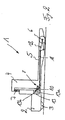
- FIGS. 1 and 2 in each case a lifting truck 1 of a Hubwagen fleet invention is shown in a side view.
- the lift truck 1 has a drive part 2, which is provided with a drive wheel 3, and a relative to the drive part 2 liftable load part 4.
- the load part 4 comprises two laterally spaced wheel arms 5, which are supported by means of load rollers 6 on the road.
- a hydraulic cylinder 7 is provided, which is arranged between the drive part 2 and the load part 4, wherein by means of a lever system 8, the load rollers 6 can be raised.
- the lever system 8 has in the region of each wheel arm 5 each have a triangular lever 10 which is articulated to the drive part 2 and the load part 4.
- the lever system 8 further comprises a linkage 11 which is hinged to the triangle lever 10 and is in communication with a toggle lever 12, which is articulated to the wheel arm 5 and carries the roller 6.
- a bearing receptacle 13 is formed for the articulated mounting of the triangular lever 10 in the region of each wheel arm 5.
- the bearing receptacle 13 has a first bearing bore 13a and a vertically spaced second bearing bore 13b.
- the triangular lever 10 has a mounting flange 15 provided with a bearing bore 15a, by means of which the triangular lever 10 can be hinged to the bearing bores 13a or 13b of the bearing seat 13, for example by means of a bearing pin.
- a first mounting flange 16 is formed, which is provided with a bearing bore 16 a.
- a second mounting flange 17 is formed, which is formed by a bearing bore 17 a.
- the triangular lever 10 is formed as an isosceles triangle, wherein the distance of the bearing bore 15a of the receiving flange 15 of the bearing bore 16a of the first mounting flange 16 and the distance of the bearing bore 15a of the receiving flange 15 of the bearing bore 17a of the second mounting flange 17 is equal.
- first mounting flange 16 of the triangular lever 10 on the load part 4 for example by means of a bearing pin
- articulated or the linkage 11 on the triangle lever 10 can be fastened, for example by means of a bearing pin.
- the triangular lever 10 by means of the second mounting flange 17 on the load part 4, for example by means of a bearing pin, articulated or on the second mounting flange 17, the linkage 11, for example by means of a bearing bolt, fastened.
- the triangular lever 10 is pivotally mounted by means of the receiving flange 15 on the bearing bore 13a of the bearing holder 13.
- the triangular lever 10 is articulated by means of the second mounting flange 17.
- the linkage 11 is fixed, which according to the FIG. 1 is designed as a pull rod for actuating the toggle lever 12.
- the triangle lever 10 is pivotally mounted by means of the receiving flange 15 on the bearing bore 13b of the bearing holder 13.
- the linkage 11 is attached to the second mounting flange 17 of the triangular lever and formed as a push rod for actuating the toggle lever 12.
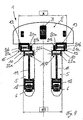
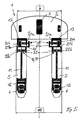
- FIGS. 4 to 6 are different trucks 1 Hubwagen fleet shown in a plan view.
- a single bearing receptacle 13 is arranged, which is formed by an inner bearing flange 20a and an outer bearing flange 20b, which are laterally spaced from one another and on which the bearing bores 13a, 13b are formed.
- the two bearing receptacles 13 are in this case for all trucks 1 Hubwagen fleet according to the FIGS. 4 to 6 arranged with an outer distance X on the drive part 2.
- the receiving flange 15 of the triangular lever 10 is formed by a respective first receiving plate 21 a and a second of the first receiving plate 21 a laterally spaced receiving plate 21 b, in which the bearing bore 15a is formed.
- the mounting flanges 16, 17 with the bearing bores 16a, 17a, by means of which the triangular lever 10 are articulated to the load part 4 and the linkage 11 are connected to the triangular levers 10 are formed on spaced bearing plates 22a, 22b.
- the triangular lever 10 is designed cranked, whereby the mounting flanges 16,17 laterally offset and thus laterally spaced from the receiving flange 15 are arranged on the triangle lever 10.
- the triangle levers 10 are fixed in a first mounting position on the bearing receivers 13.
- the first receiving plate 21a of the receiving flange 15 is in this case arranged on the inside of the outer bearing flange 20b of the bearing holder 13 and the second receiving plate 21b of the receiving flange 15 on the inner side of the inner bearing flange 20a of the bearing holder 13. Due to the cranked arrangement of the receiving flange 15 and the mounting plates formed by the bearing plates 22a, 22b mounting flanges 16, 17 a minimum Radarmabstand d1 of the two arms 5 of the load part can be achieved in this mounting position of the triangle lever.
- FIG. 5 is another lift truck 1 of the truck fleet shown, the triangle levers 10 are mounted in a second mounting position on the bearing receivers 13.
- the triangle levers 10 are in this case compared to in the FIG. 4 shown assembly position rotated by 180 ° degrees attached to the bearing receivers 13.
- the second receiving plate 21 b of the receiving flange 15 on the inside of the outer bearing flange 20 b of the bearing holder 13 and the first receiving plate 21 a of the receiving flange 15 on the inside of the inner bearing flange 20 a of the bearing holder 13 is arranged. Due to the cranked arrangement of the receiving flange 13 and the fastening plates 16, 17 formed by the bearing plates 22a, 22b, in this mounting position, a mean radar distance d2 of the two wheel arms 5 of the load part 4 can be achieved.
- the triangular lever 10 in a third, opposite to in the FIG. 5 shown assembly position laterally shifted mounting position.
- the second receiving plate 21 b of the receiving flange 15 on the outer side of the outer bearing flange 20 b of the bearing holder 13 and the first receiving plate 21 a of the receiving flange 15 on the outer side of the inner bearing flange 20 a of the bearing holder 13 is arranged.
- a pallet truck with a maximum Radarmabstand d3 of the two arms 5 of the load part 4 is due to the cranked arrangement of the mounting flange 15 and the mounting plates 22a, 22b formed mounting flanges 16, 17 achievable.
- a not shown fourth mounting position of the triangle lever 10 is possible in which the triangle lever 10 in a relation to the FIG. 4 shown assembly position laterally shifted mounting position.
- the first receiving plate 21 a of the receiving flange 15 on the outer side of the outer bearing flange 20 b of the bearing holder 13 and the second receiving plate 21 b of the receiving flange 15 on the outer side of the inner bearing flange 20 a of the bearing holder 13 is arranged, wherein a lift truck with an intermediate the Radarmabstand d1 according to the FIG. 4 and the Radarmabstand d2 according to the FIG. 5 having Radarmabstand can be formed.
- Hubwagenflotte invention When Hubwagenflotte invention is to be arranged on the drive parts 2 of the various truck 1 for each wheel 5 and thus for each triangle lever 10, only a bearing seat 13. Due to the configuration of the identical for all trucks 1 Hubwagen fleet triangle lever 10 as isosceles triangles of the triangle lever can be rotated by 180 ° to be arranged on the bearing seat 13. By at least one additional laterally displaced mounting position thus up to four mounting positions of the triangle lever 10 can be achieved on the bearing support 13 in a simple manner, whereby a Hubwagen fleet with up to four trucks, which have different Radarmbreiten with identical drive parts and identical triangular levers, made in a simple manner can be.
- the design of the linkage 11 is also possible as a pull rod or as a push rod for each Radarmabstand, creating for different lengths of the wheel arms 5 advantageous linkage can be used, for example, in short Radarminn designed as push rods linkage 11 and trained at long Radarminn or high loads of the lift truck as drawbars linkage 11th
Landscapes
- Engineering & Computer Science (AREA)
- Chemical & Material Sciences (AREA)
- Combustion & Propulsion (AREA)
- Transportation (AREA)
- Mechanical Engineering (AREA)
- Handcart (AREA)
- Forklifts And Lifting Vehicles (AREA)
- Vehicle Step Arrangements And Article Storage (AREA)
Abstract
Description
- Die Erfindung betrifft eine Hubwagenflotte, bei der jeder Hubwagen einen Antriebsteil und einen relativ zum Antriebsteil anhebbaren Lastteil aufweist, wobei der Lastteil zwei Radarme aufweist, die mit jeweils mindestens einer Lastrolle versehen sind, wobei zum Anheben des Lastteils jeweils ein mit der Lastrolle in Wirkverbindung stehendes Hebelsystem vorgesehen ist, das einen Dreieckshebel aufweist, der am Lastteil und am Antriebsteil gelenkig gelagert ist, wobei für die verschiedenen Hubwagen der Hubwagenflotte identische Dreieckshebel vorgesehen sind.
- Eine gattungsgemäße Hubwagenflotte ist aus der
EP 1 275 572 A2 bekannt. Um eine Hubwagenflotte mit verschiedenen Hubwagen herzustellen, die unterschiedliche Radarmabstände aufweisen, ist das Antriebsteil mit mehreren seitlich beabstandeten Lageraufnahmen versehen. In diese Lageraufnahmen kann ein für alle Hubwagen der Hubwagenflotte identischer Dreieckshebel, der mit den an den Radarmen des Lastteils angeordneten Lastrollen über eine Stange in Wirkverbindung steht, in verschiedenen Positionen angeordnet werden. Bei derEP 1 275 572 A2 ist es möglich, mit drei voneinander beabstandeten Lageraufnahmen am Antriebsteil den Dreieckshebel an drei verschiedenen Positionen zu montieren, wodurch eine Hubwagenflotte mit drei Hubwagen, die unterschiedlichen Radarmabständen aufweisen, hergestellt werden kann. - Bei der aus der
EP 1 275 572 A2 bekannten Hubwagenflotte weist jedoch das Antriebsteil durch die Hohe Anzahl von Lageraufnahmen einen hohen Bauaufwand und somit einen hohen Herstellaufwand auf. - Der vorliegenden Erfindung liegt die Aufgabe zugrunde, eine aus mehreren Hubwagen mit unterschiedlichen Radarmabständen bestehende Hubwagenflotte der eingangs genannten Gattung zur Verfügung zu stellen, die einen geringen Bauaufwand und Herstellaufwand aufweist.
- Diese Aufgabe wird erfindungsgemäß dadurch gelöst, dass am Antriebsteil eine einzige Lageraufnahme für den Dreieckshebel ausgebildet ist, wobei der Dreieckshebel in verschiedenen Hubwagen der Hubwagenflotte mit unterschiedlichen Radarmabständen in verschiedenen Montagepositionen an der Lageraufnahme montiert ist. Erfindungsgemäß ist somit am Antriebsteil des Hubwagens für den Dreieckshebel lediglich eine einzige Lageraufnahme ausgebildet, wobei verschiedene Radarmbreiten für unterschiedliche Hubwagen der Hubwagenflotte durch unterschiedliche Montagepositionen des identischen Dreieckshebels erzielt werden können. Das Antriebsteil, weist somit bedingt durch lediglich eine am Antriebsteil auszubildende Lageraufnahme für den Dreieckshebel einen geringen Bauaufwand und Herstellaufwand auf, wodurch eine Hubwagenflotte mit Hubwagen, die unterschiedliche Radarme aufweisen, auf einfache Weise mit geringem Herstellaufwand und Bauaufwand erzielbar ist.
- Gemäß einer Ausgestaltungsform der Erfindung ist am Dreieckshebel ein mit einer Lagerbohrung versehener Aufnahmeflansch, ein mit einer Lagerbohrung versehener erster Befestigungsflansch und ein mit einer Lagerbohrung versehener zweiter Befestigungsflansch ausgebildet, wobei der Dreieckshebel mittels des Aufnahmeflansches an der Lageraufnahme befestigbar ist, der Dreieckshebel mittels des ersten Befestigungsflansches oder des zweiten Befestigungsflansches am Lastteil gelenkig lagerbar ist und an dem zweiten Befestigungsflansches oder dem ersten Befestigungsflansches ein mit der Lastrolle in Wirkverbindung stehendes Gestänge befestigbar ist. Mit einem derartigen am Antriebsteil und am Lastteil gelenkig gelagerten Dreieckshebel kann über ein Gestänge die Lastrolle auf einfache Weise betätigt werden.
- Der Befestigungsflansch für das mit der Lastrolle in Wirkverbindung stehende Gestänge ist gemäß einer bevorzugten Ausführungsform der Erfindung seitlich versetzt zu dem Aufnahmeflansch angeordnet. Durch die seitlich versetzte und somit gekröpfte Anordnung des Aufnahmeflansches und des Befestigungsflansches können durch eine um 180° Grad verdrehte Montage und eine seitlich versetzte Montage des Dreieckshebels an der Lageraufnahme unterschiedliche Radarmabstände auf einfache Weise erzielt werden.
- Besondere Vorteile ergeben sich, wenn gemäß einer bevorzugten Weiterbildung der Erfindung der Dreieckshebel als gleichschenkliges Dreieck ausgebildet ist. Durch die Ausbildung des Dreieckshebels als gleichschenkliges Dreieck wird auf einfache Weise eine um 180° Grad verdrehte Montage des Dreieckshebels an der Lageraufnahme des Antriebsteils ermöglicht.
- Eine derartige Ausbildung des Dreieckshebels als gleichschenkliges Dreieck ist auf einfache Weise erzielbar, wenn die Lagerbohrung des Aufnahmeflansches von der Lagerbohrung des ersten Befestigungsflansches und die Lagerbohrung des Aufnahmeflansches von der Lagerbohrung des zweiten Befestigungsflansches gleiche Abstände aufweisen.
- Die Lageraufnahme ist gemäß einer vorteilhaften Ausgestaltungsform der Erfindung von einem inneren und einem äußeren Lagerflansch gebildet, wobei der Aufnahmeflansch des Dreieckshebel von einer ersten Aufnahmeplatte und einer zweiten, von der ersten Aufnahmeplatte beabstandeten Aufnahmeplatte gebildet ist. Eine derartige Lageraufnahme weist einen geringen Bauaufwand und Herstellaufwand auf, wobei der von zwei Aufnahmeplatten gebildete Aufnahmeflansch auf einfache Weise in verschiedenen Montagepositionen an dem Lagerflanschen angeordnet werden kann.
- Gemäß einer Ausgestaltungsform der Erfindung ist in einer ersten Montageposition des Dreieckshebels die erste Aufnahmeplatte an der Innenseite des äußeren Lagerflansches und die zweite Aufnahmeplatte an der Innenseite des inneren Lagerflansches angeordnet. Hierdurch kann ein Hubwagen der Hubwagenflotte mit einem ersten Radarmabstand auf einfache Weise erzeugt werden.
- Bei einer weiteren Ausgestaltungsform der Erfindung ist in einer zweiten Montageposition des Dreieckshebels die zweite Aufnahmeplatte an der Innenseite des äußeren Lagerflansches und die erste Aufnahmeplatte an der Innenseite des inneren Lagerflansches angeordnet. Durch diese Montageposition kann ein Hubwagen der Hubwagenflotte mit einem zweiten Radarmabstand auf einfache Weise hergestellt werden.
- In einer dritten Montageposition des Dreieckshebels ist gemäß einer weiteren Ausgestaltungsform der Erfindung die zweite Aufnahmeplatte an der Außenseite des äußeren Lagerflansches und die erste Aufnahmeplatte an der Außenseite des inneren Lagerflansches angeordnet. Mit dieser Montageposition kann ein Hubwagen der Hubwagenflotte mit einem dritten Radarmabstand auf einfache Weise hergestellt werden.
- Zudem kann gemäß einer Weiterbildung der Erfindung eine vierte Montageposition des Dreieckshebels erzielt werden, in der die erste Aufnahmeplatte an der Außenseite des äußeren Lagerflansches der Lageraufnahme und die zweite Aufnahmeplatte an der Außenseite des inneren Lagerflansches der Lageraufnahme angeordnet ist. Mit dieser Montageposition der Dreieckshebel kann ein Hubwagen mit einem vierten Radarmabstand auf einfache Weise hergestellt werden.
- Besondere Vorteil ergeben sich, wenn an der am Antriebsteil angeordneten Lageraufnahme eine erste Lagerbohrung und eine zweite von der ersten Lagerbohrung vertikal beabstandete Lagerbohrung ausgebildet ist, an denen der Dreieckshebel befestigbar ist. Hierdurch ist es auf einfache Weise möglich, die Anlenkung des als gleichschenkligen Dreieck ausgebildeten Dreieckshebels am Antriebsteil derart zu verändern, dass als Gestänge zur Betätigung der Lastrollen eine Druckstange oder eine Zugstange verwendet werden kann. In Abhängigkeit der Länge der Radarme kann somit ein als Zugstange oder Druckstange ausgebildetes Gestänge verwendet werden, beispielsweise bei kurzen Radarmen eine Druckstange und bei langen Radarmen eine Zugstange.
- Weitere Vorteile und Einzelheiten der Erfindung werden anhand der in den schematischen Figuren dargestellten Ausführungsbeispiele näher erläutert. Hierbei zeigt
- Figur 1
- eine erste Ausführungsform eines Hubwagens einer erfindungsgemäßen Hubwagenflotte in einer Seitenansicht,
- Figur 2
- eine zweite Ausführungsform eines Hubwagens einer erfindungsgemäßen Hubwagenflotte in einer Seitenansicht,
- Figur 3
- die Seitenansicht eines Dreieckshebels in einer vergrößerten Darstellung,
- Figur 4
- eine Draufsicht eines ersten Hubwagens einer erfindungsgemäßen Flurförderzeugflotte,
- Figur 5
- eine Draufsicht eines zweiten Hubwagens einer erfindungsgemäßen Flurförderzeugflotte und
- Figur 6
- eine Draufsicht eines dritten Hubwagens einer erfindungsgemäßen Flurförderzeugflotte.
- In den
Figuren 1 und2 ist jeweils ein Hubwagen 1 einer erfindungsgemäßen Hubwagenflotte in einer Seitenansicht dargestellt. Der Hubwagen 1 weist einen Antriebsteil 2, der mit einem Antriebsrad 3 versehen ist, und einen relativ zum Antriebsteil 2 anhebbaren Lastteil 4 auf. Der Lastteil 4 umfasst zwei seitlich beabstandete Radarme 5, die sich mittels Lastrollen 6 auf der Fahrbahn abstützen. - Zum Anheben des Lastteils ist ein Hydraulikzylinder 7 vorgesehen, der zwischen dem Antriebsteil 2 und dem Lastteil 4 angeordnet ist, wobei mittels eines Hebelsystems 8 die Lastrollen 6 anhebbar sind. Das Hebelsystem 8 weist im Bereich jedes Radarms 5 jeweils einen Dreieckshebel 10 auf, der am Antriebsteil 2 und am Lastteil 4 gelenkig befestigt ist. Das Hebelsystem 8 umfasst weiterhin ein Gestänge 11, das am Dreieckshebel 10 gelenkig befestigt ist und mit einem Kniehebel 12 in Verbindung steht, der am Radarm 5 gelenkig gelagert ist und die Laufrolle 6 trägt. Am Antriebsteil 4 ist zur gelenkigen Lagerung des Dreieckshebels 10 im Bereich jedes Radarmes 5 jeweils eine Lageraufnahme 13 ausgebildet.
- In der
Figur 3 ist die am Antriebsteil 2 angeordnete Lageraufnahme 13 und der Dreieckshebel 10 in einer vergrößerten Darstellung als Seitenansicht dargestellt. Die Lageraufnahme 13 weist eine erste Lagerbohrung 13a und eine vertikal beabstandete zweite Lagerbohrung 13b auf. Der Dreieckshebel 10 weist einen mit einer Lagerbohrung 15a versehenen Aufnahmeflansch 15 auf, mittels dem der Dreieckshebel 10 an der Lagerbohrungen 13a bzw. 13b der Lageraufnahme 13, beispielsweise mittels eines Lagerbolzens, gelenkig befestigbar ist. Am Dreieckshebel 10 ist ein erster Befestigungsflansch 16 ausgebildet, der mit einer Lagerbohrung 16a versehen ist. Zudem ist am Dreieckshebel 10 ein zweiter Befestigungsflansch 17 ausgebildet, der von einer Lagerbohrung 17a gebildet ist. - Der Dreieckshebel 10 ist als gleichschenkliges Dreieck ausgebildet, wobei der Abstand der Lagerbohrung 15a des Aufnahmeflansches 15 von der Lagerbohrung 16a des ersten Befestigungsflansches 16 und der Abstand der Lagerbohrung 15a des Aufnahmeflansches 15 von der Lagerbohrung 17a des zweiten Befestigungsflansches 17 gleich groß ist. Mittels des ersten Befestigungsflansches 16 ist der Dreieckshebel 10 am Lastteil 4, beispielsweise mittels eines Lagerbolzens, gelenkig lagerbar oder das Gestänge 11 am Dreieckshebel 10 befestigbar, beispielsweise mittels eines Lagerbolzens. Entsprechend ist der Dreieckshebel 10 mittels des zweiten Befestigungsflansches 17 am Lastteil 4, beispielsweise mittels eines Lagerbolzens, gelenkig lagerbar oder am zweiten Befestigungsflansch 17 das Gestänge 11, beispielsweise mittels eines Lagerbolzens, befestigbar.
- Bei dem in der
Figur 1 dargestellten Hubwagen 1 ist der Dreieckshebel 10 mittels des Aufnahmeflansches 15 an der Lagerbohrung 13a der Lageraufnahme 13 gelenkig gelagert. Am Lastteil 4 ist der Dreieckshebel 10 mittels des zweiten Befestigungsflansches 17 gelenkig gelagert. An dem ersten Befestigungsflansch 16 des Dreieckshebels 10 ist das Gestänge 11 befestigt, das gemäß derFigur 1 als Zugstange zur Betätigung des Kniehebels 12 ausgebildet ist. - Bei dem in der
Figur 2 dargestellten Hubwagen 1 ist der Dreieckshebel 10 mittels des Aufnahmeflansches 15 an der Lagerbohrung 13b der Lageraufnahme 13 gelenkig gelagert. Mittels des ersten Befestigungsflansches 16 ist der Dreieckshebel 10 am Lastteil 4 gelenkig befestigt. Das Gestänge 11 ist am zweiten Befestigungsflansch 17 des Dreieckshebels befestigt und als Druckstange zur Betätigung des Kniehebels 12 ausgebildet. - In den
Figuren 4 bis 6 sind verschiedene Hubwagen 1 der Hubwagenflotte in einer Draufsicht dargestellt. - Am Antriebsteil 2 der Hubwagen 1 gemäß der
Figuren 4 bis 6 ist im Bereich jedes Radarms 3 eine einzige Lageraufnahme 13 angeordnet, die von jeweils einem inneren Lagerflansch 20a und einen äußeren Lagerflansch 20b gebildet ist, die voneinander seitlich beabstandet sind und an denen die Lagerbohrungen 13a, 13b ausgebildet sind. Die beiden Lageraufnahmen 13 sind hierbei für alle Hubwagen 1 der Hubwagenflotte gemäß denFiguren 4 bis 6 mit einem Außenabstand X am Antriebsteil 2 angeordnet. - Der Aufnahmeflansch 15 der Dreieckshebel 10 ist von jeweils einer ersten Aufnahmeplatte 21 a und einer zweiten von der ersten Aufnahmeplatte 21 a seitlich beabstandeten Aufnahmeplatte 21 b gebildet, in denen die Lagerbohrung 15a ausgebildet ist. Die Befestigungsflansche 16, 17 mit den Lagerbohrungen 16a, 17a, mittels denen der Dreieckshebel 10 am Lastteil 4 gelenkig gelagert sind und die Gestänge 11 mit den Dreieckshebeln 10 verbindbar sind, sind an voneinander beabstandeten Lagerplatten 22a, 22b ausgebildet. Der Dreieckshebel 10 ist gekröpft gestaltet, wodurch die Befestigungsflansche 16,17 seitlich versetzt und somit seitlich beabstandet zu dem Aufnahmeflansch 15 an dem Dreieckshebel 10 angeordnet sind.
- Bei dem in der
Figur 4 dargestellten Hubwagen 1 der Hubwagenflotte sind die Dreieckshebel 10 in einer ersten Montageposition an den Lageraufnahmen 13 befestigt. Die erste Aufnahmeplatte 21 a des Aufnahmeflansches 15 ist hierbei an der Innenseite des äußeren Lagerflansches 20b der Lageraufnahme 13 und die zweite Aufnahmeplatte 21 b des Aufnahmeflansches 15 an der Innenseite des inneren Lagerflansches 20a der Lageraufnahme 13 angeordnet. Durch die gekröpfte Anordnung des Aufnahmeflansches 15 und der von den Lagerplatten 22a, 22b gebildeten Befestigungsflansche 16, 17 ist in dieser Montageposition der Dreieckshebel 10 ein minimaler Radarmabstand d1 der beiden Radarme 5 des Lastteils erzielbar. - In der
Figur 5 ist ein weiterer Hubwagen 1 der Hubwagenflotte dargestellt, wobei die Dreieckshebel 10 in einer zweiten Montageposition an den Lageraufnahmen 13 befestigt sind. Die Dreieckshebel 10 sind hierbei gegenüber der in derFigur 4 dargestellten Montageposition um 180° Grad gedreht an den Lageraufnahmen 13 befestigt. In dieser Montageposition der Dreieckshebels 10 ist die zweite Aufnahmeplatte 21 b des Aufnahmeflansches 15 an der Innenseite des äußeren Lagerflansches 20b der Lageraufnahme 13 und die erste Aufnahmeplatte 21a des Aufnahmeflansches 15 an der Innenseite des inneren Lagerflansches 20a der Lageraufnahme 13 angeordnet. Durch die gekröpfte Anordnung des Aufnahmeflansches 13 und der von den Lagerplatten 22a, 22b gebildeten Befestigungsflansche 16, 17 ist in dieser Montageposition ein mittlerer Radarmabstand d2 der beiden Radarme 5 des Lastteils 4 erzielbar. - Bei dem in der
Figur 6 dargestellten Hubwagen 1 der Hubwagenflotte befinden sich die Dreieckshebel 10 in einer dritten, gegenüber der in derFigur 5 dargestellten Montageposition seitlich verschobenen Montageposition. In dieser Montageposition ist die zweite Aufnahmeplatte 21 b des Aufnahmeflansches 15 an der Außenseite des äußeren Lagerflansches 20b der Lageraufnahme 13 und der erste Aufnahmeplatte 21a des Aufnahmeflansches 15 an der Außenseite des inneren Lagerflansches 20a der Lageraufnahme 13 angeordnet. In dieser Montageposition des Dreieckshebels 10 ist aufgrund der gekröpften Anordnung des Aufnahmeflansches 15 und der von den Lagerplatten 22a, 22b gebildeten Befestigungsflansche 16, 17 ein Hubwagen mit einem maximalen Radarmabstand d3 der beiden Radarme 5 des Lastteils 4 erzielbar. - Zudem ist eine nicht mehr dargestellte vierte Montageposition der Dreieckshebels 10 möglich, bei denen sich die Dreieckshebel 10 in einer gegenüber der
Figur 4 dargestellten Montageposition seitlich verschobenen Montageposition befinden. In dieser vierten Montageposition ist die erste Aufnahmeplatte 21 a des Aufnahmeflansches 15 an der Außenseite des äußeren Lagerflansches 20b der Lageraufnahme 13 und die zweite Aufnahmeplatte 21 b des Aufnahmeflansches 15 an der Außenseite des inneren Lagerflansches 20a der Lageraufnahme 13 angeordnet, wobei ein Hubwagen mit einem zwischen dem Radarmabstand d1 gemäß derFigur 4 und dem Radarmabstand d2 gemäß derFigur 5 aufweisenden Radarmabstand gebildet werden kann. - Beim der erfindungsgemäßen Hubwagenflotte ist an den Antriebsteilen 2 der verschiedenen Hubwagen 1 für jeden Radarm 5 und somit für jeden Dreieckshebel 10 lediglich eine Lageraufnahme 13 anzuordnen. Durch die Ausgestaltung der für alle Hubwagen 1 der Hubwagenflotte identischen Dreieckshebel 10 als gleichschenklige Dreiecke kann der Dreieckshebel um 180° Grad gedreht an der Lageraufnahme 13 angeordnet werden. Durch zumindest eine zusätzliche seitlich verschobene Montageposition können somit bis zu vier Montagepositionen des Dreieckshebels 10 an der Lageraufnahme 13 auf einfache Weise erzielt werden, wodurch eine Hubwagenflotte mit bis zu vier Hubwagen, die bei identischen Antriebsteilen und identischen Dreieckshebeln unterschiedliche Radarmbreiten aufweisen, auf einfache Weise hergestellt werden kann. Durch die beiden Lagerbohrungen 13a, 13b in den Lageraufnahmen 13 ist zudem für jeden Radarmabstand die Ausgestaltung des Gestänges 11 als Zugstange oder als Druckstange ermöglicht, wodurch für verschiedene Längen der Radarme 5 vorteilhafte Gestänge verwendet werden können, beispielsweise bei kurzen Radarmlängen als Druckstangen ausgebildete Gestänge 11 und bei langen Radarmlängen bzw. hohen Traglasten des Hubwagens als Zugstangen ausgebildete Gestänge 11.
Claims (11)
- Hubwagenflotte, bei der jeder Hubwagen einen Antriebsteil und einen relativ zum Antriebsteil anhebbaren Lastteil aufweist, wobei der Lastteil zwei Radarme aufweist, die mit jeweils mindestens einer Lastrolle versehen sind, wobei zum Anheben des Lastteils jeweils ein mit der Lastrolle in Wirkverbindung stehendes Hebelsystem vorgesehen ist, das einen Dreieckshebel aufweist, der am Lastteil und am Antriebsteil gelenkig gelagert ist, wobei für die verschiedenen Hubwagen der Hubwagenflotte identische Dreieckshebel vorgesehen sind, dadurch gekennzeichnet, dass am Antriebsteil (2) eine einzige Lageraufnahme (13) für den Dreieckshebel (10) ausgebildet ist, wobei der Dreieckshebel (10) in verschiedenen Hubwagen (1) der Hubwagenflotte mit unterschiedlichen Radarmabständen (d1; d2; d3) in verschiedenen Montagepositionen an der Lageraufnahme (13) montiert ist.
- Hubwagenflotte nach Anspruch 1, dadurch gekennzeichnet, dass am Dreieckshebel (10) ein mit einer Lagerbohrung (15a) versehener Aufnahmeflansch (15), ein mit einer Lagerbohrung (16a) versehener erster Befestigungsflansch (16) und ein mit einer Lagerbohrung (17a) versehener zweiter Befestigungsflansch (17) ausgebildet ist, wobei der Dreieckshebel (10) mittels des Aufnahmeflansches (15) an der Lageraufnahme (13) befestigbar ist, der Dreieckshebel (10) mittels des ersten Befestigungsflansches (16) oder des zweiten Befestigungsflansches (17) am Lastteil (4) gelenkig lagerbar ist und an dem zweiten Befestigungsflansches (17) oder dem ersten Befestigungsflansch (16) ein mit der Lastrolle (6) in Wirkverbindung stehendes Gestänge (11) befestigbar ist.
- Hubwagenflotte nach Anspruch 2, dadurch gekennzeichnet, dass der Befestigungsflansch (16; 17) für das mit der Lastrolle (6) in Wirkverbindung stehende Gestänge (11) seitlich versetzt zu dem Aufnahmeflansch (13) angeordnet ist.
- Hubwagenflotte nach einem der Ansprüche 1 bis 3, dadurch gekennzeichnet, dass der Dreieckshebel (10) als gleichschenkliges Dreieck ausgebildet ist.
- Hubwagenflotte nach Anspruch 4, dadurch gekennzeichnet, dass die Lagerbohrung (15a) des Aufnahmeflansches (15) von der Lagerbohrung (16a) des ersten Befestigungsflansches (16) und die Lagerbohrung (15a) des Aufnahmeflansches (15) von der Lagerbohrung (17a) des zweiten Befestigungsflansches (17) gleiche Abstände aufweisen.
- Hubwagenflotte nach einem der Ansprüche 1 bis 5, dadurch gekennzeichnet, dass die Lageraufnahme (13) von einem inneren Lagerflansch (20a) und einem äußeren Lagerflansch (20b) gebildet ist, wobei der Aufnahmeflansch (15) des Dreieckshebels (10) von einer ersten Aufnahmeplatte (21 a) und einer zweiten, von der ersten Aufnahmeplatte (21 a) beabstandeten Aufnahmeplatte (21 b) gebildet ist.
- Hubwagenflotte nach Anspruch 6, dadurch gekennzeichnet, dass in einer ersten Montageposition des Dreieckshebels (10) die erste Aufnahmeplatte (21 a) an der Innenseite des äußeren Lagerflansches (20b) und die zweite Aufnahmeplatte (21 b) an der Innenseite des inneren Lagerflansches (20a) angeordnet ist.
- Hubwagenflotte nach Anspruch 6 oder 7, dadurch gekennzeichnet, dass in einer zweiten Montageposition des Dreieckshebels (10) die zweite Aufnahmeplatte (21 b) an der Innenseite des äußeren Lagerflansches (20b) und die erste Aufnahmeplatte (21 a) an der Innenseite des inneren Lagerflansches (20a) angeordnet ist.
- Hubwagenflotte nach einem der Ansprüche 6 bis 8, dadurch gekennzeichnet, dass in einer dritten Montageposition des Dreieckshebels (10) die zweite Aufnahmeplatte (21 b) an der Außenseite des äußeren Lagerflansches (20b) und der erste Aufnahmeplatte (21 a) an der Außenseite des inneren Lagerflansches (20a) angeordnet ist.
- Hubwagenflotte nach einem der Ansprüche 6 bis 9, dadurch gekennzeichnet, dass in einer vierten Montageposition des Dreieckshebels (10) die erste Aufnahmeplatte (21 a) an der Außenseite des äußeren Lagerflansches (20b) der Lageraufnahme (13) und die zweite Aufnahmeplatte (21 b) an der Außenseite des inneren Lagerflansches (20a) der Lageraufnahme (13) angeordnet ist.
- Hubwagenflotte nach einem der Ansprüche 1 bis 10, dadurch gekennzeichnet, dass an der am Antriebsteil (2) angeordneten Lageraufnahme (13) eine erste Lagerbohrung (13a) und eine zweite von der ersten Lagerbohrung (13a) vertikal beabstandete Lagerbohrung (13b) ausgebildet ist, an denen der Dreieckshebel (10) befestigbar ist.
Applications Claiming Priority (1)
| Application Number | Priority Date | Filing Date | Title |
|---|---|---|---|
| DE102006061148A DE102006061148A1 (de) | 2006-12-22 | 2006-12-22 | Hubwagenflotte |
Publications (3)
| Publication Number | Publication Date |
|---|---|
| EP1935750A2 true EP1935750A2 (de) | 2008-06-25 |
| EP1935750A3 EP1935750A3 (de) | 2008-12-31 |
| EP1935750B1 EP1935750B1 (de) | 2009-10-21 |
Family
ID=39273235
Family Applications (1)
| Application Number | Title | Priority Date | Filing Date |
|---|---|---|---|
| EP07023262A Not-in-force EP1935750B1 (de) | 2006-12-22 | 2007-11-30 | Hubwagenflotte |
Country Status (4)
| Country | Link |
|---|---|
| EP (1) | EP1935750B1 (de) |
| AT (1) | ATE446233T1 (de) |
| DE (2) | DE102006061148A1 (de) |
| ES (1) | ES2334461T3 (de) |
Cited By (2)
| Publication number | Priority date | Publication date | Assignee | Title |
|---|---|---|---|---|
| EP2275319A3 (de) * | 2009-07-18 | 2012-12-26 | Jungheinrich Aktiengesellschaft | Flurförderzeug mit einer Rahmenkonstruktion |
| US20250304133A1 (en) * | 2024-03-28 | 2025-10-02 | Charles Chestnut | Pallet jack with laterally spreading and telescopically extending prongs |
Families Citing this family (1)
| Publication number | Priority date | Publication date | Assignee | Title |
|---|---|---|---|---|
| DE102014106055A1 (de) * | 2014-04-30 | 2015-11-05 | Jungheinrich Aktiengesellschaft | Flurförderzeug, insbesondere Niederhubfahrzeug |
Family Cites Families (4)
| Publication number | Priority date | Publication date | Assignee | Title |
|---|---|---|---|---|
| FR2810613B1 (fr) * | 2000-06-22 | 2002-10-18 | Loc Manutention | Dispositif a leviers de renvoi pour le relevage des fourches d'un chariot de type transpalette |
| DE10134282A1 (de) * | 2001-07-14 | 2003-01-23 | Still & Saxby Sarl | Flurförderzeugflotte und Verfahren zum Herstellen der Flurförderzeugflotte |
| TW559194U (en) * | 2002-06-25 | 2003-10-21 | Wen-Ching Li | Adjusting type pallet truck |
| US7641011B2 (en) * | 2006-03-18 | 2010-01-05 | Keith Wayne Fridlington, Jr. | Pallet jack having width-adjustable fork prongs |
-
2006
- 2006-12-22 DE DE102006061148A patent/DE102006061148A1/de not_active Withdrawn
-
2007
- 2007-11-30 EP EP07023262A patent/EP1935750B1/de not_active Not-in-force
- 2007-11-30 ES ES07023262T patent/ES2334461T3/es active Active
- 2007-11-30 AT AT07023262T patent/ATE446233T1/de not_active IP Right Cessation
- 2007-11-30 DE DE502007001784T patent/DE502007001784D1/de active Active
Cited By (2)
| Publication number | Priority date | Publication date | Assignee | Title |
|---|---|---|---|---|
| EP2275319A3 (de) * | 2009-07-18 | 2012-12-26 | Jungheinrich Aktiengesellschaft | Flurförderzeug mit einer Rahmenkonstruktion |
| US20250304133A1 (en) * | 2024-03-28 | 2025-10-02 | Charles Chestnut | Pallet jack with laterally spreading and telescopically extending prongs |
Also Published As
| Publication number | Publication date |
|---|---|
| ATE446233T1 (de) | 2009-11-15 |
| EP1935750B1 (de) | 2009-10-21 |
| EP1935750A3 (de) | 2008-12-31 |
| ES2334461T3 (es) | 2010-03-10 |
| DE102006061148A1 (de) | 2008-06-26 |
| DE502007001784D1 (de) | 2009-12-03 |
Similar Documents
| Publication | Publication Date | Title |
|---|---|---|
| EP1897842B1 (de) | Vormontageeinheit für den Antrieb eines Flurförderzeugs | |
| DE102014100865B4 (de) | Routenzuganhänger mit einem Fahrgestell und einer Transportvorrichtung | |
| EP2719603A1 (de) | Flurförderzeug mit in schwenkbaren Lastrollenträgern angeordneten Lastrollen | |
| DE102013202098A1 (de) | Selbstfahrender Transportwagen für Paletten | |
| DE102013106385B4 (de) | Scharniervorrichtung | |
| EP2275319B1 (de) | Flurförderzeug mit einer Rahmenkonstruktion | |
| DE102008017007A1 (de) | Mehrstiftverriegelungseinrichtung einer Verstellvorrichtung eines Kraftfahrzeugsitzes | |
| EP1935750B1 (de) | Hubwagenflotte | |
| EP2363308B1 (de) | Achslenker für eine luftgefederte Fahrzeugachse | |
| EP0972687B1 (de) | Schwenkfuss zur Bodenabstützung für eine Hubeinrichtung | |
| DE102011014106A1 (de) | Starrachsenanordnung in einem Fahrzeug, insbesondere in einem Nutzfahrzeug | |
| EP2334957B1 (de) | Schaltanordnung für ein schaltgetriebe | |
| DE102018112629A1 (de) | Aufbaumodul zur Anordnung an einem Fahrgestell, Wechselsystem mit dem Aufbaumodul, Fahrzeug mit dem Wechselsystem sowie Verfahren zur Zentrierung des Aufbaumoduls auf dem Fahrgestell | |
| DE102006009602A1 (de) | Traganordnung eines Behälters an einem tragenden Bauteil eines Lastkraftwagens | |
| DE102017108218A1 (de) | Höhenverstelleinrichtung eines Kraftfahrzeugsitzes sowie Verfahren zur Herstellung einer derartigen Höhenverstelleinrichtung | |
| EP3771616B1 (de) | Flurförderzeug, insbesondere hubwagen | |
| EP3290307B1 (de) | Montagevorrichtung und anhänger | |
| DE10134282A1 (de) | Flurförderzeugflotte und Verfahren zum Herstellen der Flurförderzeugflotte | |
| EP3771617B1 (de) | Deichsel für ein flurförderzeug | |
| DE102013200252A1 (de) | Satteldrehplateau | |
| EP2384928B2 (de) | Ladebordwandsystem | |
| DE202018102947U1 (de) | Aufbaumodul zur Anordnung an einem Fahrgestell, Wechselsystem mit dem Aufbaumodul sowie Fahrzeug mit dem Wechselsystem | |
| DE102006005061B4 (de) | Flurförderzeug mit mindestens zwei Radarmen und Verfahren zur Montage des Flurförderzeugs | |
| DE102007036643A1 (de) | Hubwagen | |
| EP2030837B1 (de) | Arretiervorrichtung |
Legal Events
| Date | Code | Title | Description |
|---|---|---|---|
| PUAI | Public reference made under article 153(3) epc to a published international application that has entered the european phase |
Free format text: ORIGINAL CODE: 0009012 |
|
| AK | Designated contracting states |
Kind code of ref document: A2 Designated state(s): AT BE BG CH CY CZ DE DK EE ES FI FR GB GR HU IE IS IT LI LT LU LV MC MT NL PL PT RO SE SI SK TR |
|
| AX | Request for extension of the european patent |
Extension state: AL BA HR MK RS |
|
| PUAL | Search report despatched |
Free format text: ORIGINAL CODE: 0009013 |
|
| AK | Designated contracting states |
Kind code of ref document: A3 Designated state(s): AT BE BG CH CY CZ DE DK EE ES FI FR GB GR HU IE IS IT LI LT LU LV MC MT NL PL PT RO SE SI SK TR |
|
| AX | Request for extension of the european patent |
Extension state: AL BA HR MK RS |
|
| 17P | Request for examination filed |
Effective date: 20090205 |
|
| GRAP | Despatch of communication of intention to grant a patent |
Free format text: ORIGINAL CODE: EPIDOSNIGR1 |
|
| AKX | Designation fees paid |
Designated state(s): AT BE BG CH CY CZ DE DK EE ES FI FR GB GR HU IE IS IT LI LT LU LV MC MT NL PL PT RO SE SI SK TR |
|
| GRAS | Grant fee paid |
Free format text: ORIGINAL CODE: EPIDOSNIGR3 |
|
| GRAA | (expected) grant |
Free format text: ORIGINAL CODE: 0009210 |
|
| AK | Designated contracting states |
Kind code of ref document: B1 Designated state(s): AT BE BG CH CY CZ DE DK EE ES FI FR GB GR HU IE IS IT LI LT LU LV MC MT NL PL PT RO SE SI SK TR |
|
| REG | Reference to a national code |
Ref country code: GB Ref legal event code: FG4D Free format text: NOT ENGLISH |
|
| REG | Reference to a national code |
Ref country code: CH Ref legal event code: EP |
|
| REG | Reference to a national code |
Ref country code: IE Ref legal event code: FG4D |
|
| REF | Corresponds to: |
Ref document number: 502007001784 Country of ref document: DE Date of ref document: 20091203 Kind code of ref document: P |
|
| REG | Reference to a national code |
Ref country code: SE Ref legal event code: TRGR |
|
| REG | Reference to a national code |
Ref country code: ES Ref legal event code: FG2A Ref document number: 2334461 Country of ref document: ES Kind code of ref document: T3 |
|
| LTIE | Lt: invalidation of european patent or patent extension |
Effective date: 20091021 |
|
| NLV1 | Nl: lapsed or annulled due to failure to fulfill the requirements of art. 29p and 29m of the patents act | ||
| PG25 | Lapsed in a contracting state [announced via postgrant information from national office to epo] |
Ref country code: FI Free format text: LAPSE BECAUSE OF FAILURE TO SUBMIT A TRANSLATION OF THE DESCRIPTION OR TO PAY THE FEE WITHIN THE PRESCRIBED TIME-LIMIT Effective date: 20091021 Ref country code: IS Free format text: LAPSE BECAUSE OF FAILURE TO SUBMIT A TRANSLATION OF THE DESCRIPTION OR TO PAY THE FEE WITHIN THE PRESCRIBED TIME-LIMIT Effective date: 20100221 Ref country code: LT Free format text: LAPSE BECAUSE OF FAILURE TO SUBMIT A TRANSLATION OF THE DESCRIPTION OR TO PAY THE FEE WITHIN THE PRESCRIBED TIME-LIMIT Effective date: 20091021 Ref country code: PT Free format text: LAPSE BECAUSE OF FAILURE TO SUBMIT A TRANSLATION OF THE DESCRIPTION OR TO PAY THE FEE WITHIN THE PRESCRIBED TIME-LIMIT Effective date: 20100222 |
|
| REG | Reference to a national code |
Ref country code: IE Ref legal event code: FD4D |
|
| BERE | Be: lapsed |
Owner name: OM CARRELLI ELEVATORI S.P.A. Effective date: 20091130 |
|
| PG25 | Lapsed in a contracting state [announced via postgrant information from national office to epo] |
Ref country code: SI Free format text: LAPSE BECAUSE OF FAILURE TO SUBMIT A TRANSLATION OF THE DESCRIPTION OR TO PAY THE FEE WITHIN THE PRESCRIBED TIME-LIMIT Effective date: 20091021 Ref country code: PL Free format text: LAPSE BECAUSE OF FAILURE TO SUBMIT A TRANSLATION OF THE DESCRIPTION OR TO PAY THE FEE WITHIN THE PRESCRIBED TIME-LIMIT Effective date: 20091021 Ref country code: CY Free format text: LAPSE BECAUSE OF FAILURE TO SUBMIT A TRANSLATION OF THE DESCRIPTION OR TO PAY THE FEE WITHIN THE PRESCRIBED TIME-LIMIT Effective date: 20091021 Ref country code: LV Free format text: LAPSE BECAUSE OF FAILURE TO SUBMIT A TRANSLATION OF THE DESCRIPTION OR TO PAY THE FEE WITHIN THE PRESCRIBED TIME-LIMIT Effective date: 20091021 |
|
| PG25 | Lapsed in a contracting state [announced via postgrant information from national office to epo] |
Ref country code: MC Free format text: LAPSE BECAUSE OF NON-PAYMENT OF DUE FEES Effective date: 20091130 |
|
| PG25 | Lapsed in a contracting state [announced via postgrant information from national office to epo] |
Ref country code: RO Free format text: LAPSE BECAUSE OF FAILURE TO SUBMIT A TRANSLATION OF THE DESCRIPTION OR TO PAY THE FEE WITHIN THE PRESCRIBED TIME-LIMIT Effective date: 20091021 Ref country code: EE Free format text: LAPSE BECAUSE OF FAILURE TO SUBMIT A TRANSLATION OF THE DESCRIPTION OR TO PAY THE FEE WITHIN THE PRESCRIBED TIME-LIMIT Effective date: 20091021 Ref country code: DK Free format text: LAPSE BECAUSE OF FAILURE TO SUBMIT A TRANSLATION OF THE DESCRIPTION OR TO PAY THE FEE WITHIN THE PRESCRIBED TIME-LIMIT Effective date: 20091021 Ref country code: BG Free format text: LAPSE BECAUSE OF FAILURE TO SUBMIT A TRANSLATION OF THE DESCRIPTION OR TO PAY THE FEE WITHIN THE PRESCRIBED TIME-LIMIT Effective date: 20100121 Ref country code: IE Free format text: LAPSE BECAUSE OF FAILURE TO SUBMIT A TRANSLATION OF THE DESCRIPTION OR TO PAY THE FEE WITHIN THE PRESCRIBED TIME-LIMIT Effective date: 20091021 |
|
| PLBE | No opposition filed within time limit |
Free format text: ORIGINAL CODE: 0009261 |
|
| STAA | Information on the status of an ep patent application or granted ep patent |
Free format text: STATUS: NO OPPOSITION FILED WITHIN TIME LIMIT |
|
| PG25 | Lapsed in a contracting state [announced via postgrant information from national office to epo] |
Ref country code: SK Free format text: LAPSE BECAUSE OF FAILURE TO SUBMIT A TRANSLATION OF THE DESCRIPTION OR TO PAY THE FEE WITHIN THE PRESCRIBED TIME-LIMIT Effective date: 20091021 Ref country code: CZ Free format text: LAPSE BECAUSE OF FAILURE TO SUBMIT A TRANSLATION OF THE DESCRIPTION OR TO PAY THE FEE WITHIN THE PRESCRIBED TIME-LIMIT Effective date: 20091021 |
|
| 26N | No opposition filed |
Effective date: 20100722 |
|
| PG25 | Lapsed in a contracting state [announced via postgrant information from national office to epo] |
Ref country code: GR Free format text: LAPSE BECAUSE OF FAILURE TO SUBMIT A TRANSLATION OF THE DESCRIPTION OR TO PAY THE FEE WITHIN THE PRESCRIBED TIME-LIMIT Effective date: 20100122 Ref country code: BE Free format text: LAPSE BECAUSE OF NON-PAYMENT OF DUE FEES Effective date: 20091130 |
|
| PG25 | Lapsed in a contracting state [announced via postgrant information from national office to epo] |
Ref country code: AT Free format text: LAPSE BECAUSE OF NON-PAYMENT OF DUE FEES Effective date: 20091130 |
|
| PG25 | Lapsed in a contracting state [announced via postgrant information from national office to epo] |
Ref country code: LU Free format text: LAPSE BECAUSE OF NON-PAYMENT OF DUE FEES Effective date: 20091130 Ref country code: MT Free format text: LAPSE BECAUSE OF FAILURE TO SUBMIT A TRANSLATION OF THE DESCRIPTION OR TO PAY THE FEE WITHIN THE PRESCRIBED TIME-LIMIT Effective date: 20091021 |
|
| PG25 | Lapsed in a contracting state [announced via postgrant information from national office to epo] |
Ref country code: HU Free format text: LAPSE BECAUSE OF FAILURE TO SUBMIT A TRANSLATION OF THE DESCRIPTION OR TO PAY THE FEE WITHIN THE PRESCRIBED TIME-LIMIT Effective date: 20100422 |
|
| PG25 | Lapsed in a contracting state [announced via postgrant information from national office to epo] |
Ref country code: TR Free format text: LAPSE BECAUSE OF FAILURE TO SUBMIT A TRANSLATION OF THE DESCRIPTION OR TO PAY THE FEE WITHIN THE PRESCRIBED TIME-LIMIT Effective date: 20091021 |
|
| PG25 | Lapsed in a contracting state [announced via postgrant information from national office to epo] |
Ref country code: IT Free format text: LAPSE BECAUSE OF NON-PAYMENT OF DUE FEES Effective date: 20101130 |
|
| REG | Reference to a national code |
Ref country code: CH Ref legal event code: PL |
|
| PG25 | Lapsed in a contracting state [announced via postgrant information from national office to epo] |
Ref country code: LI Free format text: LAPSE BECAUSE OF NON-PAYMENT OF DUE FEES Effective date: 20111130 Ref country code: CH Free format text: LAPSE BECAUSE OF NON-PAYMENT OF DUE FEES Effective date: 20111130 |
|
| PG25 | Lapsed in a contracting state [announced via postgrant information from national office to epo] |
Ref country code: NL Free format text: LAPSE BECAUSE OF FAILURE TO SUBMIT A TRANSLATION OF THE DESCRIPTION OR TO PAY THE FEE WITHIN THE PRESCRIBED TIME-LIMIT Effective date: 20091021 |
|
| PGFP | Annual fee paid to national office [announced via postgrant information from national office to epo] |
Ref country code: ES Payment date: 20121122 Year of fee payment: 6 |
|
| PGFP | Annual fee paid to national office [announced via postgrant information from national office to epo] |
Ref country code: GB Payment date: 20141120 Year of fee payment: 8 |
|
| REG | Reference to a national code |
Ref country code: ES Ref legal event code: FD2A Effective date: 20150708 |
|
| PG25 | Lapsed in a contracting state [announced via postgrant information from national office to epo] |
Ref country code: ES Free format text: LAPSE BECAUSE OF NON-PAYMENT OF DUE FEES Effective date: 20131201 |
|
| REG | Reference to a national code |
Ref country code: FR Ref legal event code: PLFP Year of fee payment: 9 |
|
| GBPC | Gb: european patent ceased through non-payment of renewal fee |
Effective date: 20151130 |
|
| PG25 | Lapsed in a contracting state [announced via postgrant information from national office to epo] |
Ref country code: GB Free format text: LAPSE BECAUSE OF NON-PAYMENT OF DUE FEES Effective date: 20151130 |
|
| REG | Reference to a national code |
Ref country code: FR Ref legal event code: PLFP Year of fee payment: 10 |
|
| REG | Reference to a national code |
Ref country code: FR Ref legal event code: PLFP Year of fee payment: 11 |
|
| PGFP | Annual fee paid to national office [announced via postgrant information from national office to epo] |
Ref country code: IT Payment date: 20171122 Year of fee payment: 11 |
|
| REG | Reference to a national code |
Ref country code: DE Ref legal event code: R082 Ref document number: 502007001784 Country of ref document: DE Representative=s name: PATENTSHIP PATENTANWALTSGESELLSCHAFT MBH, DE Ref country code: DE Ref legal event code: R081 Ref document number: 502007001784 Country of ref document: DE Owner name: STILL S.P.A., IT Free format text: FORMER OWNER: OM CARRELLI ELEVATORI S.P.A., LAINATE, IT |
|
| PG25 | Lapsed in a contracting state [announced via postgrant information from national office to epo] |
Ref country code: IT Free format text: LAPSE BECAUSE OF NON-PAYMENT OF DUE FEES Effective date: 20181130 |
|
| PGFP | Annual fee paid to national office [announced via postgrant information from national office to epo] |
Ref country code: SE Payment date: 20221122 Year of fee payment: 16 Ref country code: FR Payment date: 20221118 Year of fee payment: 16 Ref country code: DE Payment date: 20221121 Year of fee payment: 16 |
|
| P01 | Opt-out of the competence of the unified patent court (upc) registered |
Effective date: 20230510 |
|
| REG | Reference to a national code |
Ref country code: DE Ref legal event code: R119 Ref document number: 502007001784 Country of ref document: DE |
|
| REG | Reference to a national code |
Ref country code: SE Ref legal event code: EUG |
|
| PG25 | Lapsed in a contracting state [announced via postgrant information from national office to epo] |
Ref country code: DE Free format text: LAPSE BECAUSE OF NON-PAYMENT OF DUE FEES Effective date: 20240601 |
|
| PG25 | Lapsed in a contracting state [announced via postgrant information from national office to epo] |
Ref country code: FR Free format text: LAPSE BECAUSE OF NON-PAYMENT OF DUE FEES Effective date: 20231130 |
|
| PG25 | Lapsed in a contracting state [announced via postgrant information from national office to epo] |
Ref country code: FR Free format text: LAPSE BECAUSE OF NON-PAYMENT OF DUE FEES Effective date: 20231130 Ref country code: DE Free format text: LAPSE BECAUSE OF NON-PAYMENT OF DUE FEES Effective date: 20240601 |
|
| PG25 | Lapsed in a contracting state [announced via postgrant information from national office to epo] |
Ref country code: SE Free format text: LAPSE BECAUSE OF NON-PAYMENT OF DUE FEES Effective date: 20231201 |