EP1935542A1 - Werkzeugmaschine mit einer Rast- und Klemmeinrichtung - Google Patents
Werkzeugmaschine mit einer Rast- und Klemmeinrichtung Download PDFInfo
- Publication number
- EP1935542A1 EP1935542A1 EP07021014A EP07021014A EP1935542A1 EP 1935542 A1 EP1935542 A1 EP 1935542A1 EP 07021014 A EP07021014 A EP 07021014A EP 07021014 A EP07021014 A EP 07021014A EP 1935542 A1 EP1935542 A1 EP 1935542A1
- Authority
- EP
- European Patent Office
- Prior art keywords
- clamping
- latching
- actuating
- machine tool
- tool according
- Prior art date
- Legal status (The legal status is an assumption and is not a legal conclusion. Google has not performed a legal analysis and makes no representation as to the accuracy of the status listed.)
- Granted
Links
- 210000003811 finger Anatomy 0.000 claims description 8
- 238000005520 cutting process Methods 0.000 claims description 5
- 238000003754 machining Methods 0.000 claims description 3
- 238000000151 deposition Methods 0.000 claims description 2
- 210000003813 thumb Anatomy 0.000 claims description 2
- ZZUFCTLCJUWOSV-UHFFFAOYSA-N furosemide Chemical compound C1=C(Cl)C(S(=O)(=O)N)=CC(C(O)=O)=C1NCC1=CC=CO1 ZZUFCTLCJUWOSV-UHFFFAOYSA-N 0.000 abstract 1
- 208000027418 Wounds and injury Diseases 0.000 description 1
- 230000006378 damage Effects 0.000 description 1
- 239000000428 dust Substances 0.000 description 1
- 210000005224 forefinger Anatomy 0.000 description 1
- 208000014674 injury Diseases 0.000 description 1
- 230000002093 peripheral effect Effects 0.000 description 1
- 238000003825 pressing Methods 0.000 description 1
- 239000004575 stone Substances 0.000 description 1
- 238000003860 storage Methods 0.000 description 1
- 239000000758 substrate Substances 0.000 description 1
Images

Classifications
-
- B—PERFORMING OPERATIONS; TRANSPORTING
- B27—WORKING OR PRESERVING WOOD OR SIMILAR MATERIAL; NAILING OR STAPLING MACHINES IN GENERAL
- B27B—SAWS FOR WOOD OR SIMILAR MATERIAL; COMPONENTS OR ACCESSORIES THEREFOR
- B27B5/00—Sawing machines working with circular or cylindrical saw blades; Components or equipment therefor
- B27B5/29—Details; Component parts; Accessories
-
- B—PERFORMING OPERATIONS; TRANSPORTING
- B23—MACHINE TOOLS; METAL-WORKING NOT OTHERWISE PROVIDED FOR
- B23D—PLANING; SLOTTING; SHEARING; BROACHING; SAWING; FILING; SCRAPING; LIKE OPERATIONS FOR WORKING METAL BY REMOVING MATERIAL, NOT OTHERWISE PROVIDED FOR
- B23D45/00—Sawing machines or sawing devices with circular saw blades or with friction saw discs
- B23D45/04—Sawing machines or sawing devices with circular saw blades or with friction saw discs with a circular saw blade or the stock carried by a pivoted lever
- B23D45/042—Sawing machines or sawing devices with circular saw blades or with friction saw discs with a circular saw blade or the stock carried by a pivoted lever with the saw blade carried by a pivoted lever
- B23D45/046—Sawing machines or sawing devices with circular saw blades or with friction saw discs with a circular saw blade or the stock carried by a pivoted lever with the saw blade carried by a pivoted lever the pivoted lever being mounted on a carriage
- B23D45/048—Sawing machines or sawing devices with circular saw blades or with friction saw discs with a circular saw blade or the stock carried by a pivoted lever with the saw blade carried by a pivoted lever the pivoted lever being mounted on a carriage the saw blade being adjustable according to angle of cut
-
- B—PERFORMING OPERATIONS; TRANSPORTING
- B23—MACHINE TOOLS; METAL-WORKING NOT OTHERWISE PROVIDED FOR
- B23D—PLANING; SLOTTING; SHEARING; BROACHING; SAWING; FILING; SCRAPING; LIKE OPERATIONS FOR WORKING METAL BY REMOVING MATERIAL, NOT OTHERWISE PROVIDED FOR
- B23D47/00—Sawing machines or sawing devices working with circular saw blades, characterised only by constructional features of particular parts
- B23D47/02—Sawing machines or sawing devices working with circular saw blades, characterised only by constructional features of particular parts of frames; of guiding arrangements for work-table or saw-carrier
- B23D47/025—Sawing machines or sawing devices working with circular saw blades, characterised only by constructional features of particular parts of frames; of guiding arrangements for work-table or saw-carrier of tables
Definitions
- the invention relates to a machine tool, in particular a saw, for the separating machining of a workpiece, with a pivotable about a pivot axis about a pivot axis pivoting part, with a latching device, which latched with a manually operated latching actuator between a latched with a latching base, the pivoting part of the Pivoting base rotatably holding detent position and a latch release position is adjustable, and with a clamping actuator which is adjustable with a manually operable clamping device between a clamping base on a clamping base, the pivoting part on the pivot base rotatably holding clamping position and a clamping release position, wherein the pivoting part with respect to the pivot base is rotatable when the latching device in the latch release position and the clamping device in the terminal release position.
- Such a machine tool for example, in the form of a lifting saw with a capping table from the DE 198 03 955 A1 known.
- a turntable for placing a workpiece is mounted rotatably or pivotably on a capping table. According to the angular position of the turntable, miter cuts can be made with the hoist saw.
- a latching device provides detent positions for different angular positions of the turntable.
- a clamping screw serves as a clamping device and allows free setting of the Pivoting part or turntable at angular positions between the lockable angular positions.
- the arbitrary angles of the pivoting part are only infinitely adjustable when the release button is kept pressed, so that the locking device is not locked in the region of the locking positions.
- the clamping screw or clamping device is locked according to the selected angular position of the turntable.
- the clamping screw and the unlocking button are inconvenient to use.
- a locking actuating handle of the locking actuator and a clamping actuating handle of the clamping actuator are arranged close to each other so that held with one hand, the locking actuator in the locking release position and the clamping device between the clamping position and the terminal release position can be adjusted.
- the locking actuating handle and the clamping actuating handle can be operated with one hand. Thereby, it is easily possible to hold the latching actuating handle in the latch release position while the clamping device is operated.
- the locking actuating handle is moved relative to the clamping actuating handle to achieve the locking release position.
- the machine tool is expediently a miter saw.
- the application of the invention miter miter saws or miter saws is advantageous.
- the cutting tool can also be a cutting disk, for example for cutting tiles, stone or the like.
- the latching device and the clamping device are expediently arranged on the pivoting part, while the latching base and the clamping base are arranged on the pivoting base.
- the latching device and the clamping device can also be arranged on the non-rotatable pivot base and the latching base and the clamping base on the pivotable part.
- the pivoting part is, for example, a workpiece table for depositing a workpiece.
- the swivel base or swivel base conveniently comprises a machine bed in this case.
- the pivoting part may also be a pivotable stop of a workpiece table.
- the pivoting part forms a pivoting carrier for pivoting a separating device or sawing device of the machine tool, wherein the separating device or sawing device contains a tool drivable by a drive motor.
- the separating or sawing device can be brought into the desired angular position or pivoting position with one hand.
- the latching device and the clamping device can form components of an integrated holding device. Furthermore, the latching device and the clamping device can be arranged in a housing of the pivoting part, for example the workpiece table or the pivoting carrier.
- the clamping actuating handle or latching actuating handle which contain, for example, handles or operating projections, are expediently in front of the pivoting part.
- the respective actuating handle advantageously forms an operating handle for pivoting the pivoting part.
- the pivot member can be pivoted by grasping the clamp actuating handle or the latch actuating handle.
- the clamping actuating handle advantageously contains a handpiece which can be grasped by hand.
- the latching actuating handle may comprise, for example, a finger-operated finger-operated piece.
- the operator can embrace the handpiece and at the same time hold the finger operating piece with a finger, for example his or her thumb or forefinger, in the detent release position or detent release position.
- the latching actuating handle includes an operating projection, which engages around when grasping the handpiece of the clamping actuating handle and thus, so to speak, is automatically actuated in the direction of the latch release position.
- the latching base advantageously contains arcuately arranged latching receptacles or latching projections.
- the locking receptacles are arranged on a plate-like arch part.
- the clamping base it is advantageous if it is formed by a preferably plate-like arch part.
- the latching base and the clamping base are formed by two separate sheet parts.
- the clamping base and the latching base are formed by a single plate-like arched part.
- the latching receptacles or latching projections can also be arranged, for example, on a housing or housing body of the pivoting base.
- the latching receptacles or latching projections are arranged, for example, on an outer circumference, on an inner circumference, on the upper side or on the underside of the latching base.
- a variant is realized in which the latching receptacles or latching projections are arranged on an inner circumference of the arched part, whereas a clamping part of the clamping base is formed by an outer circumferential region of the arched part.
- the clamping device or the latching device are expediently spring-loaded in the direction of their respective clamping or latching position. Then the clamping actuator and the latch actuator are only required to bring the clamping device or the latching device in their respective release position. The provision in the respective holding position takes place automatically.
- the latching device advantageously contains in the direction of the latching position spring-loaded, operable by the latching actuating device latching part for latching with the latching base.
- the locking member is resilient in itself, for example, consists of a resilient plate.
- an additional spring arrangement is provided, which acts on the locking part. With the locking actuator, the locking part can be brought into the locking release position. By the spring arrangement or return arrangement, the locking part is acted upon in the locking position. Thus, the locking part automatically engages in the locked position.
- the detent member may be a separate component or may also form part of the detent actuator, e.g. a latching projection or a latching recess on the latching actuator.
- the clamping device includes a spring-loaded preferably in the direction of the clamping position, by the clamping actuator actuatable clamping part for clamping with the clamping base. Also this clamping part can be resilient. Furthermore, it is possible that the clamping part is spring-loaded by a spring arrangement in the direction of the clamping position.
- the clamping part is eg plate-like part.
- clamping part Even with the clamping part, it is conceivable to arrange them directly on the actuating device. Furthermore, it is possible for the clamping part to form part of a separate component from the clamping actuating device.
- the latching part and the clamping part expediently act from opposite sides on the latching base and the clamping base.
- the clamping device for example the clamping actuator is expediently fixed in the clamping position or the clamping release position, e.g. with a latching arrangement or a locking device. It is conceivable that the clamping device can only be fixed in one of the two positions, e.g. in the clamping position, or in both positions.
- the latching device it is also advantageous if it can be fixed in the latching position or the latch release position.
- the setting can be effected for example by a spring which acts on the latching device in the detent position.
- the latching device can be latched in the latching position or the latch release position by means of a latching arrangement. Although this is not realized in the embodiment.
- By corresponding locking projections or locking receptacles a locking of the locking device in the locking position and / or the locking release position is readily possible.
- the latching actuator and the clamping actuator may be motion coupled. In an actuating action on the clamping actuator, for example, the locking actuator is taken. Nevertheless, the latching actuator remains advantageous in its respective detent position or latch release position, even if it is taken away by the clamping actuator.
- the locking actuator is mounted freely movable so that they can hold the respective locking release position or detent position at an adjustment of the clamping actuator between the clamping release position and the clamping position.
- the clamping actuator is adjustable without the latching device leaves its respective position.
- the locking actuator and the clamping actuator are each movably mounted on a holder, such as a housing.
- a holder such as a housing.
- the latching actuating device is mounted on the clamping actuating device or the clamping actuating device on the latching actuating device.
- the latching actuating device advantageously comprises a latching actuating lever with an actuating section for adjusting the latching device into the latching release position and / or the latching position. Also in the clamping actuator, it is useful if it contains a clamping operation lever, which brings the clamping device with an actuating part in the terminal release position or the clamping position.
- the clamping actuating lever is expediently mounted pivotably in the region of its actuating part.
- the clamping actuating lever is mounted on a housing. It is advantageous Kerblagerung. Due to the storage in the area of the actuating part, a long lever arm is available, so that the clamping of the clamping device can be easily canceled even if it clamps the pivoting part on the clamping base with a large clamping force, for example with a strong spring.
- Locking arrangements for holding the actuating lever in its respective position are expediently arranged on the latching actuating lever and / or on the clamping actuating lever.
- the actuating lever then remains in the release position or the holding position.
- the latching arrangements are arranged in the region of the respective actuating part of the actuating lever.
- corresponding latching arrangements can be arranged.
- a variant is realized in which engages a locking arrangement of the clamping actuating lever in the locking position in a recess on the clamping part.
- the sliding arrangement slides, for example, along the clamping part or locking part. The roller rolls on the locking part or clamping part.
- the latching actuating lever is expediently mounted pivotably on the clamping actuating lever.
- the lever axis is advantageously located in a central portion of the clamping actuating lever. This in turn is suitably pivotally mounted in front, in the region of its actuating part.
- the clamp actuating lever has a longer lever arm than the latching lever. From the common lever axis the two operating lever, however, the operating parts of the locking actuating lever and the clamping operation lever each advantageously have the same lever spacing.
- the common lever axis of the locking actuating lever and the clamping actuating lever expediently have a longitudinal distance to a pivot axis of the clamping actuating lever.
- the actuating part of the locking actuating lever and a pivot bearing of the clamping actuating lever are advantageously arranged close to each other.
- the actuating portion of the detent actuating lever is adjacent to the pivotal mounting of the clamping actuating lever, e.g. a Kerblagerung arranged.
- the pivotal mounting of the clamping actuating lever and the actuating part of the latching actuating lever, in particular when it assumes its latching release position, are arranged next to one another, for example, in the axial direction of the pivot axis of the clamping actuating lever.
- the actuating part is positioned between two pivot bearing portions of the clamping operating lever.
- a saw 10 has a sawing device 11 with a rotatably mounted circular saw blade 12 which is drivable by a drive motor 13. Thus, the saw 10 forms a machine tool 14 for the cutting machining of a workpiece 15.
- the sawing device 11 is movable for sawing the workpiece 15 in several degrees of freedom: the sawing device 11 is rotatable about a vertical, ie in the y-direction axis of rotation 17 to a horizontal, extending in the z-direction oblique pivot axis 18 in different oblique pivot positions schrägverschwenkbar about a Kappschwenkachse 19 pivotally and also parallel to the inclined pivot axis 18 on a linear guide 20, ie in the z-direction, linearly adjustable.
- a machine bed 22 of the saw 10 forms a pivoting base 23 for a pivoting part 24, which is rotatably mounted on the pivoting base 23 about the axis of rotation 17, which in this respect forms a pivot axis.
- the machine bed 22 can be lowered with feet 25 on a substrate.
- fastening means may be provided, for example, height adjustment and / or screw holes for screwing to the ground.
- a substantially cylindrical work table body 26 of the pivot member 24 is rotatably received between workpiece table projections projecting laterally upward in front of a bottom portion 28 of the pivot base 23. Upper sides of the body 26 and the projections 27 form a bearing surface 29 of a workpiece table 30 for placing the workpiece 15.
- Radially inner front sides of the projections 27 are corresponding to the round outer periphery of the body 26 around.
- Vertical side surfaces 31 of the projections 27 form pivot stops for an actuating arm 32 of the pivoting part 24, which protrudes radially outward in front of the body 26.
- a kerf 33 extends on bearing surface 29 of the body 26 approximately from the axis of rotation 17 to the radially outer, free end of the actuating arm 32.
- the upper side of the actuating arm 32 forms a bearing surface of the workpiece table 30th
- a stop member 34 is arranged on the stop plates 35 to form the vertical stop 16 are fastened. Between the stop plates 35 a space is available.
- the pivoting part 24 can be secured against rotation relative to the axis of rotation 17 by means of a latching device 36 or a clamping device 37.
- the latching device 36 locks with a latching base 38 at latching positions.
- the clamping device 37 can also be fixed to a clamping base 39 between the latching positions.
- An arch part 40 which is arranged on a front side of the bottom part 28, forms the latching base 38 and the clamping base 39.
- a swivel angle scale 41 Arranged on an upper side of the arch part 40 is a swivel angle scale 41.
- a latching actuating handle 42 and a clamping actuating handle 43 project radially outward in front of the actuating arm 32 of a latching actuator 44 and a clamping actuator 45. At least the clamping actuating handle 43 forms an operating handle for pivoting the pivoting part 24. With the actuators 44, 45, the latching device 36 and the clamping device 37 between a pivotal part on the pivot base 23 rotatably holding stop position and a pivoting enabling release position can be adjusted.
- the actuating handles 42, 43 are arranged directly next to one another.
- the clamping actuator can be adjusted between a terminal release position and a clamping position, while the same hand holds the latch actuator in the latch release position, so that the latching device 36 is not locked to the latching base 38.
- a swivel angle is thus freely selectable, even between locking positions of the locking device.
- a Schrägschwenkbasis 46 is arranged with a pivot bearing 47 to which a slanted-pivot support 48 is pivotally mounted about the oblique pivot axis 18.
- a bearing housing 50 From a radially in front of the workpiece table body 26 projecting support arm 49 is a bearing housing 50 upwards.
- an arcuate toothing 51 On the arcuate top side of the bearing housing 50 extends an arcuate toothing 51.
- a stepped disc 52 is positioned, which also has an arcuate upper end face.
- a Schrägschwenkwinkelskala 53 for displaying the respective oblique pivot angle of the pivot support 48 is arranged.
- the teeth 51 form part of a Schrägschwenkgetriebes 54, with which a respective Schrägschwenkposition of the pivot support 48 and thus arranged on this sawing device 11 is adjustable.
- the oblique pivot gear 54 is arranged in a pivot carrier housing 55 of the pivot carrier 48.
- Guide tubes 56 project horizontally in front of the pivot carrier 48.
- the guide tubes 56 are linear guide elements 57 of the linear guide 20.
- a saw carriage 58 is guided linearly on the linear guide elements 57. For example, penetrate the guide tubes 56 guide bushings 59 of the saw carriage 58.
- the sawing device 11 is pivotably mounted on the saw carriage 58 about the cap pivot axis 19 on a pivot bearing 60.
- the sawing device 11 can be gripped by an operator on a handle 61 on its housing 62 and pivoted about the cap pivot axis 19 or pulled along the linear guide axis 21.
- a saw guard 63 is pivotally mounted on the housing 62, which protects against injury by the saw blade 12, but when sawing pivots into the housing 62 and the saw blade 12 releases.
- a suction connection 64 dust occurring during sawing can be sucked off.
- the oblique pivot gear 54 can be operated from the front side of the saw 10.
- a shaft 65, which leads to the oblique pivoting gear 54, of an actuating device 66 of the oblique pivoting gear 54 is arranged in an inner space of the guide tube 56 which is on the right in the drawing.
- a handle 67 projects in front of the front, free end of the guide tube 56 and can be conveniently gripped and rotated by an operator. According to the direction of rotation when turning the handle 67, the oblique pivoting gear 54 pivots the pivoting carrier 48 about the inclined pivot axis 18.
- the latching actuating device 44 includes a latching actuating lever 68, the clamping actuator 45 a clamping actuating lever 69. At the respective front, free ends of the actuating lever 68, 69 are actuating parts 70, 71 for actuating a latching part 72 and a clamping part 73rd
- the latching part 72 locks at predetermined rotational positions of the pivoting part 24 with latching recesses 74 on the latching base 38.
- the latching recesses 74, into which a latching projection 75 engages, are arranged on an inner circumference of the arched part 40 and define latching positions.
- the locking part 72 and the clamping part 73 are resilient stamped and bent parts.
- the locking part 72 and the clamping part 73 are biased in their respective holding position.
- the latching part 72 and the clamping part 73 are fastened, for example, to a housing 76 of the actuating arm 32.
- mounting holes 77 are provided.
- the clamping part 73 is supported on a housing projection 78 of the housing 76.
- the housing projection 78 protrudes downwards.
- the clamping part 73 is supported with its rear side on the housing projection 78. While the locking member 72 engages from above into the recesses 74, the clamping member 73 clamps the clamping base 39 from below.
- the clamping part 73 is clamped against an outer circumferential part 79 of the arch part 40 from below.
- the outer peripheral part 79 is free.
- the clamping part 73 protrudes radially inward between the bottom part 28 and the arch part 40th
- the clamp member 73 clamps the clamp base 39 from below.
- the latching part 72 locks from above with the latching base 38.
- the clamping actuating lever 69 is pivotally mounted in the region of its actuating portion 71, that is, at its front free end. At the bottom of the front free end of the actuating portion 71. At the top of the free end a notched bearing 80 is arranged with a bearing notch 81 on the clamping actuating lever 69, in which a housing 76 arranged on the bearing projection 82 engages. The bearing projection 82 projects downward in front of the housing 76. Due to the spring tension of the clamping part 73, the clamping actuating lever 69 is biased in the direction of the notch bearing 80, so that the bearing notch 81 remains in the bearing projection 82.
- the latching actuating lever 68 is mounted pivotably about a lever axis 83 on the clamping actuating lever 69.
- the lever axis 83 is located approximately in a middle region of the clamping actuating lever 69.
- the latching operating lever 68 is arranged like a rider on the clamping actuating lever 69.
- Arms 84 of the latching actuating lever 68 extend laterally on the clamping actuating lever 69.
- the actuating lever 68, 69 could be penetrated by an axle shaft.
- bearing projections 85 are provided, which engage in corresponding recesses on the side surfaces of the clamping actuating lever 69.
- the operating levers 68, 69 project in front of the housing 76 of the actuating arm 32. At the free end of the actuating lever 68, 69 located there, the two actuating handles 42, 43 are arranged.
- the clamp actuating handle 43 includes a handle 86 which can be encompassed with an operating hand and has a spherical shape.
- the handpiece 86 can be grasped with one hand.
- the operating hand can simultaneously actuate a finger actuating piece 87 of the locking actuating handle 42.
- the operating piece 87 is disposed at one end of the arms 84 and connects them.
- the finger operating piece 87 has a grip recess 88 for engagement with a finger of the operating hand.
- the handpiece 86 suitably has a corrugation.
- the latching arrangement 91 is arranged in the region of the actuating part 71.
- the latching arrangement 91 comprises a roller 93 which is rotatably mounted on the underside of the clamping actuating lever 69 on a rotary bearing 92 and which rolls on the clamping part 73. In the clamping position, the roller 93 engages in a groove-like recess 94 of the clamping member 73 a. When displacing into the clamp release position, the roller 93 rolls out of the recess 94.
- the actuating portion 71 pivots advantageous in an adjustment of the clamping in the release position via a tilt position 100, so that the clamping actuating lever 69 remains stable even in its release position.
- the operating portion 71 of the clamping operating lever 69 acts on a front, free end of the clamping member 73, that is close to the region where the clamping member 73 presses against the clamping base 39. Further, the operating portion 71 is disposed at the front end of the clamp operating lever 69, so that the operating force for displacing the clamp 37 in the clamp release position is small, even if the clamp 37 jams the swing member 324 with great force on the swing base 23.
- the operating lever 68, 69 are suitably made of plastic.
- a rib or honeycomb arrangement 95 may be provided.
- the latching actuating portion 70 is disposed at the front, free ends of the arms 84.
- the actuating portion 70 comprises two upwardly projecting, suitably curved, e.g. hump-like actuating projections 96, which cooperate on actuating areas of actuating arms 97 of the locking part 72.
- the projections 96 engage under the actuating arms 97.
- the arms 97 are bent in correspondence with the curvature of the actuating projections 96.
- the actuating arms 97 are resiliently on the actuating projections 96.
- the actuating projections 96 may be interconnected to improve stability.
- the notch bearing 80 is disposed between the operating protrusions 96.
- the actuating projections 96 In the detent position are the actuating projections 96 approximately at the same height as the bearing notch 81. Then, a middle portion 98 of the actuating arms 97 rests on the bearing projections 96.
- the actuating projections 96 By pressing the latching operating lever 68 downward, the actuating projections 96 are moved upwards and lift the actuating arms 97, so that the latching projection 75 is disengaged from a respective latching recess 74. Then, the pivot member 24 can be further pivoted.
- end portions 99 at the free ends of the actuating arms 97, to the actuating projections 96, for example, at the upper head portion.
- the front end of the end portion 99 abuts against the upper curved portion of the operation projection 96.
- the end portions 99 extend toward the operating projection 96.
- the end portions 99 are also in the locking release position so far beyond vertexes of the actuating projections 96, that the actuating projections 96 are always in engagement with the actuating arms 97.
- the operating arms 97 do not "snap" in front of the actuating projections 96.
- the latching part 72 In the case of pivoting-angle positions between the latching recesses 74, the latching part 72, in particular its latching projection 75, rests resiliently on the upper side of the curved part 40. Upon further pivoting of the pivoting part 24, the latching projection 75 engages in the respective next latching recess 74 when the latching actuating device 44 is in the latching position.
- the latching recesses 74 are arranged in an arc shape on the swivel base 23.
Landscapes
- Engineering & Computer Science (AREA)
- Mechanical Engineering (AREA)
- Life Sciences & Earth Sciences (AREA)
- Wood Science & Technology (AREA)
- Forests & Forestry (AREA)
- Sawing (AREA)
Abstract
Description
- Die Erfindung betrifft eine Werkzeugmaschine, insbesondere eine Säge, zur trennenden Bearbeitung eines Werkstücks, mit einem an einer Schwenkbasis um eine Schwenkachse schwenkbaren Schwenkteil, mit einer Rasteinrichtung, die mit einer manuell bedienbaren Rast-Betätigungseinrichtung zwischen einer mit einer Rastbasis verrasteten, das Schwenkteil an der Schwenkbasis drehfest haltenden Raststellung und einer Rastfreigabestellung verstellbar ist, und mit einer Klemm-Betätigungseinrichtung, die mit einer manuell bedienbaren Klemmeinrichtung zwischen einer an einer Klemmbasis klemmenden, das Schwenkteil an der Schwenkbasis drehfest haltenden Klemmstellung und einer Klemmfreigabestellung verstellbar ist, wobei das Schwenkteil bezüglich der Schwenkbasis drehbar ist, wenn die Rasteinrichtung in der Rastfreigabestellung und die Klemmeinrichtung in der Klemmfreigabestellung sind.
- Eine solche Werkzeugmaschine ist beispielsweise in Gestalt einer Hubsäge mit einem Kapptisch aus der
DE 198 03 955 A1 bekannt. Ein Drehtisch zum Auflegen eines Werkstückes ist an einem Kapptisch drehbar oder schwenkbar gelagert. Entsprechend der Winkelposition des Drehtisches können Gehrungsschnitte mit der Hubsäge durchgeführt werden. Eine Rasteinrichtung stellt Rastpositionen für verschiedene Winkelpositionen des Drehtisches bereit. Eine Klemmschraube dient als Klemmeinrichtung und ermöglicht ein freies Festlegen des Schwenkteils bzw. Drehtisches an Winkelpositionen zwischen den rastbaren Winkelpositionen. - Die beliebigen Winkel des Schwenkteils sind nur dann stufenlos einstellbar, wenn die Entriegelungstaste gedrückt gehalten wird, so dass die Rasteinrichtung im Bereich der Rastpositionen nicht verrastet. Die Klemmschraube oder Klemmeinrichtung wird entsprechend der gewählten Winkelposition des Drehtisches arretiert. Die Klemmschraube und die Entriegelungstaste sind unbequem zu bedienen.
- Es ist daher die Aufgabe der Erfindung, eine Werkzeugmaschine bereitzustellen, bei der eine Klemm-Betätigungseinrichtung und eine Rast-Betätigungseinrichtung ergonomisch günstig zum Klemmen des Schwenkteils zwischen Rastposition der Rasteinrichtung bedient werden können.
- Zur Lösung der Aufgabe ist bei einer Werkzeugmaschine der eingangs genannten Art vorgesehen, dass eine Rast-Betätigungshandhabe der Rast-Betätigungseinrichtung und eine Klemm-Betätigungshandhabe der Klemm-Betätigungseinrichtung derart nahe beieinander angeordnet sind, dass mit einer Hand die Rast-Betätigungseinrichtung in der Rastfreigabestellung gehalten und die Klemmeinrichtung zwischen der Klemmstellung und der Klemmfreigabestellung verstellt werden können.
- Die Rast-Betätigungshandhabe und die Klemm-Betätigungshandhabe sind mit einer Hand bedienbar. Dadurch ist es leicht möglich, die Rast-Betätigungshandhabe in der Rastfreigabestellung zu halten, während die Klemmeinrichtung bedient wird. Vorteilhaft wird zum Erreichen der Rastfreigabestellung die Rast-Betätigungshandhabe relativ zu der Klemm-Betätigungshandhabe hin bewegt.
- Die Werkzeugmaschine ist zweckmäßigerweise eine Gehrungssäge. Auch die Anwendung der Erfindung bei Gehrungskappsägen oder Gehrungszugkappsägen ist vorteilhaft. Das Trennwerkzeug kann aber auch eine Trennscheibe sein, beispielsweise zum Schneiden von Fliesen, Stein oder dergleichen.
- Die Rasteinrichtung und die Klemmeinrichtung sind zweckmäßigerweise an dem Schwenkteil angeordnet, während die Rastbasis und die Klemmbasis an der Schwenkbasis angeordnet sind. Die Rasteinrichtung und die Klemmeinrichtung können auch an der drehfesten Schwenkbasis und die Rastbasis und die Klemmbasis an dem schwenkbaren Teil angeordnet sein.
- Bei dem Schwenkteil handelt es sich beispielsweise um einen Werkstücktisch zum Ablegen eines Werkstücks. Die Schwenkbasis oder Drehbasis umfasst in diesem Fall zweckmäßigerweise ein Maschinenbett. Das Schwenkteil kann auch ein schwenkbarer Anschlag eines Werkstücktisches sein. Ferner ist es denkbar, dass das Schwenkteil einen Schwenkträger zum Verschwenken einer Trenneinrichtung oder Sägeeinrichtung der Werkzeugmaschine bildet, wobei die Trenneinrichtung oder Sägeeinrichtung ein durch einen Antriebsmotor antreibbares Werkzeug enthält. Die Trenn- oder Sägeeinrichtung kann mit einer Hand in die gewünschte Winkelposition oder Schwenkposition gebracht werden.
- Die Rasteinrichtung und die Klemmeinrichtung können Bestandteile einer integrierten Halteeinrichtung bilden. Ferner können die Rasteinrichtung und die Klemmeinrichtung in einem Gehäuse des Schwenkteils, beispielsweise des Werkstücktisches oder des Schwenkträgers, angeordnet sein.
- Die Klemm-Betätigungshandhabe oder Rast-Betätigungshandhabe, die beispielsweise Handgriffe oder Bedienvorsprünge enthalten, stehen zweckmäßigerweise vor das Schwenkteil vor. Die jeweilige Betätigungshandhabe bildet vorteilhaft eine Bedienhandhabe zum Schwenken des Schwenkteils. Somit kann das Schwenkteil durch Ergreifen der Klemm-Betätigungshandhabe oder der Rast-Betätigungshandhabe geschwenkt werden.
- Vorteilhaft enthält die Klemm-Betätigungshandhabe ein mit der Hand umgreifbares Handstück. Die Rast-Betätigungshandhabe kann beispielsweise ein mit einem Finger betätigbares Finger-Betätigungsstück umfassen. Der Bediener kann das Handstück umgreifen und zugleich das Finger-Betätigungsstück mit einem Finger, beispielsweise seinem Daumen oder Zeigefinger, in der Rastlösestellung oder Rastfreigabestellung halten.
- Es ist auch möglich, dass die Rast-Betätigungshandhabe einen Bedienvorsprung enthält, der beim Umgreifen des Handstückes der Klemm-Betätigungshandhabe mit umgriffen und damit sozusagen automatisch in Richtung der Rastfreigabestellung betätigt wird.
- Die Rastbasis enthält vorteilhaft bogenförmig angeordnete Rastaufnahmen oder Rastvorsprünge. Beispielsweise sind die Rastaufnahmen an einem plattenartigen Bogenteil angeordnet. Auch bei der Klemmbasis ist es vorteilhaft, wenn sie durch ein vorzugsweise plattenartiges Bogenteil gebildet ist. Es ist möglich, dass die Rastbasis und die Klemmbasis durch zwei separate Bogenteile gebildet sind. Vorzugsweise sind die Klemmbasis und die Rastbasis jedoch durch ein einziges plattenartiges Bogenteil gebildet. Es versteht sich, dass die Rastaufnahmen oder Rastvorsprünge auch beispielsweise an einem Gehäuse oder Gehäusekörper der Schwenkbasis angeordnet sein können.
- Die Rastaufnahmen oder Rastvorsprünge sind beispielsweise an einem Außenumfang, an einem Innenumfang, der Ober- oder der Unterseite der Rastbasis angeordnet. Beim Ausführungsbeispiel ist eine Variante realisiert, bei der die Rastaufnahmen oder Rastvorsprünge an einem Innenumfang des Bogenteils angeordnet sind, wohingegen eine Klemmpartie der Klemmbasis durch einen Außenumfangsbereich des Bogenteils gebildet ist.
- Die Klemmeinrichtung oder die Rasteinrichtung sind zweckmäßigerweise in Richtung ihrer jeweiligen Klemm- bzw. Raststellung federbeaufschlagt. Dann werden die Klemm-Betätigungseinrichtung und die Rast-Betätigungseinrichtung nur benötigt, um die Klemmeinrichtung oder die Rasteinrichtung in ihre jeweilige Freigabestellung zu bringen. Die Rückstellung in die jeweilige Haltestellung erfolgt selbsttätig.
- Die Rasteinrichtung enthält vorteilhaft in Richtung der Raststellung federbeaufschlagtes, durch die Rast-Betätigungseinrichtung betätigbares Rastteil zum Verrasten mit der Rastbasis. Beispielsweise ist das Rastteil in sich federnd, besteht beispielsweise aus einer federnden Platte. Ferner ist es möglich, dass eine zusätzliche Federanordnung vorgesehen ist, die auf das Rastteil wirkt. Mit der Rast-Betätigungseinrichtung ist das Rastteil in die Rastfreigabestellung bringbar. Durch die Federanordnung oder Rückstellanordnung wird das Rastteil in die Raststellung beaufschlagt. Somit rastet das Rastteil selbstständig in die Raststellung ein. Das Rastteil kann ein separates Bauteil sein oder auch einen Bestandteil der Rast-Betätigungseinrichtung bilden, z.B. ein Rastvorsprung oder eine Rastausnehmung an der Rast-Betätigungseinrichtung.
- Die Klemmeinrichtung enthält ein vorzugsweise in Richtung der Klemmstellung federbeaufschlagtes, durch die Klemm-Betätigungseinrichtung betätigbares Klemmteil zum Verklemmen mit der Klemmbasis. Auch dieses Klemmteil kann federnd sein. Ferner ist es möglich, dass das Klemmteil durch eine Federanordnung in Richtung der Klemmstellung federbelastet ist. Das Klemmteil ist z.B. plattenartiges Teil.
- Auch bei der Klemmpartie ist es denkbar, sie unmittelbar an der Betätigungseinrichtung anzuordnen. Ferner ist es möglich, dass die Klemmpartie einen Bestandteil eines von der Klemm-Betätigungseinrichtung separaten Bauelementes bildet.
- Das Rastteil und das Klemmteil wirken zweckmäßigerweise von entgegengesetzten Seiten her auf die Rastbasis und die Klemmbasis.
- Die Klemmeinrichtung, beispielsweise die Klemm-Betätigungseinrichtung ist zweckmäßigerweise in der Klemmstellung oder der Klemmfreigabestellung festlegbar, z.B. mit einer Rastanordnung oder einer Verriegelungseinrichtung. Es ist denkbar, dass die Klemmeinrichtung nur in einer der beiden Stellung festlegbar ist, z.B. in der Klemmstellung, oder in beiden Stellungen.
- Bei der Rasteinrichtung ist es auch vorteilhaft, wenn sie in der Raststellung oder der Rastfreigabestellung festlegbar ist. Das Festlegen kann z.B. durch eine Feder bewirkt sein, die die Rasteinrichtung in die Raststellung beaufschlagt. Ferner ist denkbar, dass die Rasteinrichtung in der Raststellung oder der Rastfreigabestellung mittels eine Rastanordnung verrastet werden kann. Beim Ausführungsbeispiel ist dies zwar nicht realisiert. Durch entsprechende Rastvorsprünge oder Rastaufnahmen ist ein Einrasten der Rasteinrichtung in der Raststellung und/oder der Rastfreigabestellung ohne weiteres möglich.
- Die Rast-Betätigungseinrichtung und die Klemm-Betätigungseinrichtung können bewegungsgekoppelt sein. Bei einer Betätigungshandlung an der Klemm-Betätigungseinrichtung wird beispielsweise die Rast-Betätigungseinrichtung mitgenommen. Dennoch bleibt die Rast-Betätigungseinrichtung vorteilhaft in ihrer jeweiligen Raststellung oder Rastfreigabestellung, auch wenn sie von der Klemm-Betätigungseinrichtung mitgenommen wird.
- Zweckmäßigerweise ist die Rast-Betätigungseinrichtung derart frei beweglich gelagert, dass sie bei einem Verstellen der Klemm-Betätigungseinrichtung zwischen der Klemmfreigabestellung und der Klemmstellung die jeweilige Rastfreigabestellung oder Raststellung halten kann. Mithin ist also die Klemm-Betätigungseinrichtung verstellbar, ohne dass die Rasteinrichtung ihre jeweilige Stellung verlässt.
- Es ist möglich, dass die Rast-Betätigungseinrichtung und die Klemm-Betätigungseinrichtung jeweils beweglich an einem Halter, beispielsweise einem Gehäuse, gelagert sind. Eine vorteilhafte Variante der Erfindung sieht aber vor, dass die Rast-Betätigungseinrichtung an der Klemm-Betätigungseinrichtung oder die Klemm-Betätigungseinrichtung an der Rast-Betätigungseinrichtung gelagert ist.
- Die Rast-Betätigungseinrichtung umfasst vorteilhaft einen Rast-Betätigungshebel mit einer Betätigungspartie zum Verstellen der Rasteinrichtung in die Rastfreigabestellung und/oder die Raststellung. Auch bei der Klemm-Betätigungseinrichtung ist es zweckmäßig, wenn sie einen Klemmbetätigungshebel enthält, der die Klemmeinrichtung mit einer Betätigungspartie in die Klemmfreigabestellung oder die Klemmstellung bringt.
- Der Klemm-Betätigungshebel ist zweckmäßigerweise im Bereich seiner Betätigungspartie schwenkbar gelagert. Beispielsweise ist der Klemm-Betätigungshebel an einem Gehäuse gelagert. Dabei ist Kerblagerung vorteilhaft. Durch die Lagerung im Bereich der Betätigungspartie steht ein langer Hebelarm zur Verfügung, so dass die Klemmung der Klemmeinrichtung auch dann leicht aufgehoben werden kann, wenn diese mit einer großen Klemmkraft, beispielsweise mit einer starken Feder, das Schwenkteil an der Klemmbasis festklemmt.
- An dem Rast-Betätigungshebel und/oder an dem Klemm-Betätigungshebel sind zweckmäßigerweise Rastanordnungen zum Halten des Betätigungshebels in seiner jeweiligen Stellung angeordnet. Der Betätigungshebel bleibt dann in der Freigabestellung oder der Haltestellung. Beispielsweise sind die Rastanordnungen im Bereich der jeweiligen Betätigungspartie des Betätigungshebels angeordnet. Aber auch abseits der Betätigungspartien, beispielsweise an einer Längsseite des jeweiligen Betätigungshebels, können entsprechende Rastanordnungen angeordnet sein. Beim Ausführungsbeispiel ist eine Variante realisiert, bei der eine Rastanordnung des Klemm-Betätigungshebels in der Raststellung in eine Ausnehmung am Klemmteil eingreift. Eine solche Bauart wäre auch ohne weiteres bei dem Rast-Betätigungshebel denkbar. Die Gleitanordnung gleitet beispielsweise an dem Klemmteil oder Rastteil entlang. Die Walze rollt auf dem Rastteil oder Klemmteil.
- Der Rast-Betätigungshebel ist zweckmäßigerweise schwenkbar an dem Klemm-Betätigungshebel gelagert. Die Hebelachse befindet sich vorteilhaft in einem Mittelabschnitt des Klemm-Betätigungshebels. Dieser wiederum ist zweckmäßigerweise vorn, im Bereich seiner Betätigungspartie, schwenkbar gelagert. Somit hat der Klemm-Betätigungshebel einen längeren Hebelarm als der Rast-Betätigungshebel. Von der gemeinsamen Hebelachse der beiden Betätigungshebel hingegen haben die Betätigungspartien des Rast-Betätigungshebels und des Klemmbetätigungshebels jeweils vorteilhaft denselben Hebelabstand.
- Möglich ist es prinzipiell auch, den Klemm-Betätigungshebel am Rast-Betätigungshebel schwenkbar zu lagern.
- Die gemeinsame Hebelachse des Rast-Betätigungshebels und des Klemm-Betätigungshebels haben zweckmäßigerweise einen Längsabstand zu einer Schwenkachse des Klemm-Betätigungshebels.
- Die Betätigungspartie des Rast-Betätigungshebels und eine Schwenklagerung des Klemm-Betätigungshebels sind vorteilhaft nahe beieinander angeordnet. Beispielsweise ist die Betätigungspartie des Rast-Betätigungshebels neben der Schwenklagerung des Klemm-Betätigungshebels, z.B. einer Kerblagerung, angeordnet. Die Schwenklagerung des Klemm-Betätigungshebels und die Betätigungspartie des Rast-Betätigungshebels, insbesondere wenn dieser seine Rastfreigabestellung einnimmt, sind beispielsweise in Achsrichtung der Schwenkachse des Klemm-Betätigungshebels nebeneinander angeordnet. Beispielsweise ist die Betätigungspartie zwischen zwei Schwenklagerabschnitten des Klemm-Betätigungshebels positioniert.
- Nachfolgend wird ein Ausführungsbeispiel anhand der Zeichnung erläutert. Es zeigen:
- Figur 1
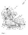
- eine Vorderansicht einer Werkzeugmaschine in Gestalt einer Gehrungssäge mit einer Klemmeinrichtung und einer Rasteinrichtung, die teilweise in einem Gehäuse eines Schwenkteils der Werkzeugmaschine angeordnet sind,
- Figur 2
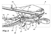
- eine Teilansicht etwa entsprechend einem Ausschnitt A in
Figur 1 mit der Rasteinrichtung und der Klemmeinrichtung bei teilweise geöffnetem Gehäuse des Schwenkteils, - Figur 3a
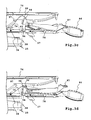
- eine etwa dem Ausschnitt gemäß
Figur 2 entsprechende Seitenansicht der Rasteinrichtung und der Klemmeinrichtung, beide im Freigabezustand, - Figur 3b
- die Ansicht gemäß
Figur 3a , wobei die Rasteinrichtung in ihrer Raststellung, die Klemmeinrichtung in ihrer Klemmfreigabestellung ist, - Figur 3c
- die Ansicht gemäß
Figur 3a , wobei die Rasteinrichtung in die Rastfreigabestellung gelöst, die Klemmeinrichtung in die Klemmstellung geklemmt ist, und - Figur 3d
- die Ansicht gemäß
Figur 3a , wobei die Rasteinrichtung in ihrer Raststellung und die Klemmeinrichtung in ihrer Klemmstellung sind. - Eine Säge 10 hat eine Sägeeinrichtung 11 mit einem drehbar gelagerten Kreis-Sägeblatt 12, das durch einen Antriebsmotor 13 antreibbar ist. Somit bildet die Säge 10 eine Werkzeugmaschine 14 zur trennenden Bearbeitung eines Werkstücks 15. Die Sägeeinrichtung 11 ist zum Sägen des Werkstücks 15 in mehreren Freiheitsgraden beweglich: die Sägeeinrichtung 11 ist um eine vertikale, das heißt in y-Richtung verlaufende Drehachse 17 drehbar, um eine horizontale, in z-Richtung verlaufende Schrägschwenkachse 18 in verschiedene Schrägschwenkpositionen schrägverschwenkbar, um eine Kappschwenkachse 19 schwenkbar und zudem noch parallel zur Schrägschwenkachse 18 an einer Linearführung 20, d.h. in z-Richtung, linear verstellbar.
- Durch Drehen bzw. Schwenken der Sägeeinrichtung 11 um die Drehachse 17 bezüglich eines Vertikalanschlages 16 können Gehrungsschnitte durchgeführt werden. Somit erfüllt die Säge 10 die Funktion einer Gehrungssäge. Die Möglichkeit, die Sägeeinrichtung 11 um die Kappschwenkachse 19 zu schwenken, macht die Säge 10 zu einer Kappsäge. Der Linearfreiheitsgrad, die Sägeeinrichtung 11 an der Linearführung 20 entlang einer Linearführungsachse 21 linear hin und her zu bewegen bzw. zu ziehen, kennzeichnet die Säge 10 als eine Zug-Säge und im Zusammenhang mit dem Kappschwenken als Zug-Kappsäge. Durch Schrägschwenken der Sägeeinrichtung 11 um die Schrägschwenkachse 18 sind schräge Schnitte möglich.
- Ein Maschinenbett 22 der Säge 10 bildet eine Schwenkbasis 23 für ein Schwenkteil 24, das um die Drehachse 17, die insoweit eine Schwenkachse bildet, drehbar an der Schwenkbasis 23 gelagert ist. Das Maschinenbett 22 ist mit Füßen 25 auf einem Untergrund abstellbar. An den Füßen 25 können Befestigungseinrichtungen vorgesehen sein, beispielsweise Höhenverstelleinrichtungen und/oder Schrauböffnungen zum Anschrauben an dem Untergrund.
- Ein im Wesentlichen zylindrischer Werktisch-Körper 26 des Schwenkteils 24 ist zwischen Werkstücktisch-Vorsprüngen drehbar aufgenommen, die vor ein Bodenteil 28 der Schwenkbasis 23 seitlich nach oben vorstehen. Oberseiten des Körpers 26 und der Vorsprünge 27 bilden eine Auflagefläche 29 eines Werkstücktischs 30 zum Auflegen des Werkstücks 15.
- Radial innere Vorderseiten der Vorsprünge 27 sind korrespondierend mit dem runden Außenumfang des Körpers 26 rund. Vertikale Seitenflächen 31 der Vorsprünge 27 bilden Schwenkanschläge für einen Betätigungsarm 32 des Schwenkteils 24, der nach radial außen vor den Körper 26 vorsteht. Ein Sägeschlitz 33 erstreckt sich an Auflagefläche 29 des Körpers 26 etwa von der Drehachse 17 bis zum radial äußeren, freien Ende des Betätigungsarms 32. Auch die Oberseite des Betätigungsarms 32 bildet eine Auflagefläche des Werkstücktisches 30.
- An der Oberseite der Vorsprünge 27 ist ein Anschlagteil 34 angeordnet, an dem Anschlagplatten 35 zur Bildung des Vertikalanschlages 16 befestigbar sind. Zwischen den Anschlagplatten 35 ist ein Freiraum vorhanden.
- Das Schwenkteil 24 ist bezüglich der Drehachse 17 mit Hilfe einer Rasteinrichtung 36 oder einer Klemmeinrichtung 37 drehfest festlegbar. Die Rasteinrichtung 36 verrastet mit einer Rastbasis 38 an Rastpositionen. Die Klemmeinrichtung 37 ist an einer Klemmbasis 39 auch zwischen den Rastpositionen festlegbar.
- Ein Bogenteil 40, das an einer Vorderseite des Bodenteils 28 angeordnet ist, bildet die Rastbasis 38 und die Klemmbasis 39. An einer Oberseite des Bogenteils 40 ist eine Schwenkwinkelskala 41 angeordnet.
- Eine Rast-Betätigungshandhabe 42 und eine Klemm-Betätigungshandhabe 43 stehen nach radial außen vor den Betätigungsarm 32 einer Rast-Betätigungseinrichtung 44 und einer Klemm-Betätigungseinrichtung 45 vor. Zumindest die Klemm-Betätigungshandhabe 43 bildet eine Bedienhandhabe zum Schwenken des Schwenkteils 24. Mit den Betätigungseinrichtungen 44, 45 können die Rasteinrichtung 36 und die Klemmeinrichtung 37 zwischen einer das Schwenkteil an der Schwenkbasis 23 drehfest haltenden Haltestellung und einer ein Schwenken ermöglichenden Freigabestellung verstellt werden.
- Die Betätigungshandhaben 42, 43 sind unmittelbar nebeneinander angeordnet. Somit kann mit einer Hand die Klemm-Betätigungseinrichtung zwischen einer Klemmfreigabestellung und einer Klemmstellung verstellt werden, während dieselbe Hand die Rast-Betätigungseinrichtung in der Rastfreigabestellung hält, so das die Rasteinrichtung 36 nicht mit der Rastbasis 38 verrastet. Ein Schwenkwinkel ist somit frei wählbar, auch zwischen Rastpositionen der Rasteinrichtung.
- An der dem Betätigungsarm 32 entgegengesetzten Seite des Schwenkteils 24 ist eine Schrägschwenkbasis 46 mit einem Schwenklager 47 angeordnet, an dem ein Schräg-Schwenkträger 48 um die Schrägschwenkachse 18 schwenkbar gelagert ist. Von einem radial vor den Werkstücktisch-Körper 26 vorstehenden Tragarm 49 steht ein Lagergehäuse 50 nach oben ab. An der bogenförmigen Oberseite des Lagergehäuses 50 verläuft eine bogenförmige Zahnung 51. Neben der Zahnung 51 ist eine Stufenscheibe 52 positioniert, die ebenfalls eine bogenförmige obere Stirnseite hat. An der Vorderseite der Stufenscheibe 52 ist eine Schrägschwenkwinkelskala 53 zur Anzeige des jeweiligen Schrägschwenkwinkels des Schwenkträgers 48 angeordnet.
- Die Zahnung 51 bildet einen Bestandteil eines Schrägschwenkgetriebes 54, mit dem eine jeweilige Schrägschwenkposition des Schwenkträgers 48 und somit der an diesem angeordneten Sägeeinrichtung 11 einstellbar ist. Das Schrägschwenkgetriebe 54 ist in einem Schwenkträgergehäuse 55 des Schwenkträgers 48 angeordnet.
- Führungsrohre 56 stehen horizontal vor den Schwenkträger 48 vor. Die Führungsrohre 56 sind Linearführungselemente 57 der Linearführung 20. Ein Sägeschlitten 58 ist an den Linearführungselementen 57 linear geführt. Beispielsweise durchdringen die Führungsrohre 56 Führungsbuchsen 59 des Sägeschlittens 58.
- Die Sägeeinrichtung 11 ist an einem Kapp-Schwenklager 60 an dem Sägeschlitten 58 um die Kappschwenkachse 19 schwenkbar gelagert. Die Sägeeinrichtung 11 kann von einem Bediener an einem Handgriff 61 an ihrem Gehäuse 62 ergriffen werden und um die Kappschwenkachse 19 geschwenkt oder entlang der Linearführungsachse 21 gezogen werden. In dem Gehäuse 62 ist der Antriebsmotor 13 aufgenommen. Ferner ist an dem Gehäuse 62 ein Sägeschutz 63 schwenkbar gelagert, der vor Verletzungen durch das Sägeblatt 12 schützt, beim Sägen jedoch in das Gehäuse 62 einschwenkt und das Sägeblatt 12 freigibt. An einem Absauganschluss 64 kann beim Sägen auftretender Staub abgesaugt werden.
- Das Schrägschwenkgetriebe 54 ist von der Vorderseite der Säge 10 her bedienbar. Eine zum Schrägschwenkgetriebe 54 führende Welle 65 einer Betätigungseinrichtung 66 des Schrägschwenkgetriebes 54 ist in einem Innenraum des in der Zeichnung rechten Führungsrohrs 56 angeordnet. Ein Handgriff 67 steht vor das vordere, freie Ende des Führungsrohres 56 vor und kann bequem von einem Bediener ergriffen und gedreht werden. Entsprechend dem Drehsinn beim Drehen des Handgriffes 67 schwenkt das Schrägschwenkgetriebe 54 den Schwenkträger 48 um die Schrägschwenkachse 18.
- Die Rast-Betätigungseinrichtung 44 enthält einen Rast-Betätigungshebel 68, die Klemm-Betätigungseinrichtung 45 einen Klemm-Betätigungshebel 69. An den jeweils vorderen, freien Enden der Betätigungshebel 68, 69 sind Betätigungspartien 70, 71 zum Betätigen eines Rastteils 72 und eines Klemmteils 73.
- Das Rastteil 72 verrastet an vorbestimmten Drehpositionen des Schwenkteils 24 mit Rastausnehmungen 74 an der Rastbasis 38. Die Rastausnehmungen 74, in die ein Rastvorsprung 75 eingreift, sind an einem Innenumfang des Bogenteils 40 angeordnet und definieren Rastpositionen.
- Das Rastteil 72 und das Klemmteil 73 sind in sich federnde Stanz-Biegeteile. Das Rastteil 72 und das Klemmteil 73 sind in ihre jeweilige Haltestellung vorgespannt.
- Das Rastteil 72 und das Klemmteil 73 sind beispielsweise an einem Gehäuse 76 des Betätigungsarms 32 befestigt. Dafür sind beispielsweise Befestigungsbohrungen 77 vorgesehen. Ferner stützt sich das Klemmteil 73 an einem Gehäusevorsprung 78 des Gehäuses 76 ab. Der Gehäusevorsprung 78 steht nach unten vor. Das Klemmteil 73 stützt sich mit seiner Rückseite an dem Gehäusevorsprung 78 ab. Während das Rastteil 72 von oben her in die Rastausnehmungen 74 eingreift, klemmt das Klemmteil 73 die Klemmbasis 39 von unten. Das Klemmteil 73 ist gegen eine Außenumfangspartie 79 des Bogenteils 40 von unten her gespannt. Die Außenumfangspartie 79 steht frei. Das Klemmteil 73 ragt nach radial innen zwischen das Bodenteil 28 und das Bogenteil 40.
- Das Klemmteil 73 klemmt die Klemmbasis 39 von unten. Das Rastteil 72 verrastet von oben mit der Rastbasis 38.
- Der Klemm-Betätigungshebel 69 ist im Bereich seiner Betätigungspartie 71, das heißt an seinem vorderen freien Ende schwenkbar gelagert. An der Unterseite des vorderen freien Endes ist die Betätigungspartie 71. An der Oberseite des freien Endes ist ein Kerblager 80 mit einer Lagerkerbe 81 am Klemm-Betätigungshebel 69 angeordnet, in die ein am Gehäuse 76 angeordneter Lagervorsprung 82 eingreift. Der Lagervorsprung 82 steht nach unten vor das Gehäuse 76 vor. Durch die Federspannung des Klemmteils 73 wird der Klemm-Betätigungshebel 69 in Richtung des Kerblagers 80 vorgespannt, so dass die Lagerkerbe 81 in dem Lagervorsprung 82 bleibt.
- Der Rast-Betätigungshebel 68 ist um eine Hebelachse 83 schwenkbar an dem Klemm-Betätigungshebel 69 gelagert. Die Hebelachse 83 befindet sich etwa in einem mittleren Bereich des Klemm-Betätigungshebels 69.
- Der Rast-Betätigungshebel 68 ist reiterartig an dem Klemm-Betätigungshebel 69 angeordnet. Arme 84 des Rast-Betätigungshebels 68 verlaufen seitlich an dem Klemm-Betätigungshebel 69. Zur Bildung der Hebelachse 83 könnten die Betätigungshebel 68, 69 von einer Achs-Welle durchdrungen sein. An der Innenseite der Arme 84 sind jedoch LagerVorsprünge 85 vorgesehen, die in korrespondierende Ausnehmungen an den Seitenflächen des Klemm-Betätigungshebels 69 eingreifen.
- Die Betätigungshebel 68, 69 stehen vor das Gehäuse 76 des Betätigungsarms 32 vor. An dem dort befindlichen freien Ende der Betätigungshebel 68, 69 sind die beiden Betätigungshandhaben 42, 43 angeordnet. Die Klemm-Betätigungshandhabe 43 enthält ein mit einer Bedien-Hand umgreifbares Handstück 86 mit einer balligen Gestalt. Das Handstück 86 kann mit einer Hand umgriffen werden. Die Bedien-Hand kann zugleich ein Finger-Betätigungsstück 87 der Rast-Betätigungshandhabe 42 betätigen. Das Betätigungsstück 87 ist an einem Ende der Arme 84 angeordnet und verbindet diese. Am Finger-Betätigungsstück 87 ist eine Griffmulde 88 zum Eingreifen mit einem Finger der Bedien-Hand vorhanden. Ein Bediener kann den Rast-Betätigungshebel 68 mit dem Finger nach unten drücken und ihn so in seine Rastfreigabestellung bringen, während er durch Auf- und Abbewegen des Klemm-Betätigungshebels 69 am Handstück 86 die Klemmung der Klemmeinrichtung 37 aufhebt oder herbeiführt. Das Handstück 86 hat zweckmäßigerweise eine Riffelung.
- Beim Verstellen des Rast-Betätigungshebels 68 in die Rastfreigabestellung schlägt dieser mit einer Anschlagfläche 89 an Anschlagflächen 90 des Klemm-Betätigungshebels 69 an. Die Anschlagfläche 89, 90 sind im Bereich zwischen der Hebelachse 83 und den Betätigungshandhaben 42, 43 angeordnet. Die Anschlagflächen 89, 90 sind derart positioniert und ausgestaltet, dass der Rast-Betätigungshebel 68 so frei an dem Klemm-Betätigungshebel 69 schwenkbeweglich ist, dass er die Rastfreigabestellung und Raststellung unabhängig davon einnehmen kann, ob der Klemm-Betätigungshebel 69 in seiner Klemmstellung oder seiner Klemmfreigabestellung ist. Auch zwischen dem Klemm-Betätigungshebel 69 und dem Bereich der Arme 84 zwischen der Hebelachse 83 und den Betätigungspartien 70 ist dementsprechend ausreichend Spiel vorgesehen.
- Während der Rast-Betätigungshebel 68 durch den Bediener in seiner jeweiligen Halte- oder Freigabestellung gehalten werden muss, rastet der Klemm-Betätigungshebel 69 mit Hilfe einer Rastanordnung 91 zumindest in seiner Klemmstellung ein. Die Rastanordnung 91 ist im Bereich der Betätigungspartie 71 angeordnet. Die Rastanordnung 91 umfasst eine an der Unterseite des Klemm-Betätigungshebels 69 an einem Drehlager 92 drehbar gelagerte Walze 93, die auf dem Klemmteil 73 abrollt. In der Klemmstellung greift die Walze 93 in eine rinnenartige Ausnehmung 94 des Klemmteils 73 ein. Beim Verlagern in die Klemmfreigabestellung rollt die Walze 93 aus der Ausnehmung 94.
- Ferner schwenkt die Betätigungspartie 71 vorteilhaft bei einem Verstellen von der Klemm- in die Freigabestellung über eine Kippposition 100, so dass der Klemm-Betätigungshebel 69 auch in seiner Freigabestellung stabil verbleibt.
- Die Betätigungspartie 71 des Klemm-Betätigungshebels 69 wirkt auf ein vorderes, freies Ende des Klemmteils 73, also nahe an dem Bereich, wo das Klemmteil 73 an die Klemmbasis 39 drückt. Ferner ist die Betätigungspartie 71 am vorderen Ende des Klemm-Betätigungshebels 69 angeordnet, so dass die Bedienkraft zum Verlagern der Klemmeinrichtung 37 in die Klemmfreigabestellung klein ist, auch wenn die Klemmeinrichtung 37 das Schwenkteil 324 mit großer Kraft an der Schwenkbasis 23 verklemmt.
- Die Betätigungshebel 68, 69 bestehen zweckmäßigerweise aus Kunststoff. Zur Verstärkung der Betätigungshebel 68, 69 kann eine Rippen- oder Wabenanordnung 95 vorgesehen sein.
- Die Rast-Betätigungspartie 70 ist an den vorderen, freien Enden der Arme 84 angeordnet. Die Betätigungspartie 70 umfasst zwei nach oben vorstehende, zweckmäßigerweise gekrümmte, z.B. höckerartige Betätigungsvorsprünge 96, die auf Betätigungsbereiche von Betätigungsarmen 97 des Rastteils 72 zusammenwirken. Die Vorsprünge 96 untergreifen die Betätigungsarme 97. Die Arme 97 sind korrespondierend mit der Krümmung der Betätigungsvorsprünge 96 gebogen. Die Betätigungsarme 97 liegen federnd auf den Betätigungsvorsprüngen 96 auf.
- Die Betätigungsvorsprünge 96 können zur Verbessung der Stabilität miteinander verbunden sein.
- Das Kerblager 80 ist zwischen den Betätigungsvorsprüngen 96 angeordnet. In der Raststellung befinden sich die Betätigungsvorsprünge 96 etwa auf derselben Höhe wie die Lagerkerbe 81. Dann liegt ein mittlerer Abschnitt 98 der Betätigungsarme 97 auf den Lagervorsprüngen 96 auf. Durch Drücken des Rast-Betätigungshebels 68 nach unten werden die Betätigungsvorsprünge 96 nach oben verstellt und heben die Betätigungsarme 97 an, so dass der Rastvorsprung 75 außer Eingriff mit einer jeweiligen Rastausnehmung 74 gelangt. Dann kann das Schwenkteil 24 weiter geschwenkt werden.
- In der dann erreichten Rastfreigabestellung liegen Endabschnitte 99 an den freien Enden der Betätigungsarme 97, an den Betätigungsvorsprüngen 96 an, beispielsweise an deren oberem Kopfabschnitt. In der Rastfreigabestellung liegt das vordere Ende des Endabschnitts 99 am oberen, gekrümmten Abschnitt des Betätigungsvorsprungs 96 an. Die Endabschnitte 99 verlaufen zu dem Betätigungsvorsprung 96 hin. Die Endabschnitte 99 stehen auch in der Rastfreigabestellung derart weit über Scheitelpunkte der Betätigungsvorsprünge 96 vor, dass die Betätigungsvorsprünge 96 stets im Eingriff mit den Betätigungsarmen 97 sind. Die Betätigungsarme 97 "schnappen" nicht vor die Betätigungsvorsprünge 96 vor.
- Bei Schwenkwinkelpositionen zwischen den Rastausnehmungen 74 liegt das Rastteil 72, insbesondere dessen Rastvorsprung 75, federnd auf der Oberseite des Bogenteiles 40 auf. Beim Weiterschwenken des Schwenkteils 24 rastet der Rastvorsprung 75 in die jeweils nächste Rastausnehmung 74 ein, wenn die Rast-Betätigungseinrichtung 44 in der Raststellung ist.
- Die Rastausnehmungen 74 sind bogenförmig an der Schwenkbasis 23 angeordnet.
Claims (24)
- Werkzeugmaschine, insbesondere Säge (10), zur trennenden Bearbeitung eines Werkstücks (15), mit einem an einer Schwenkbasis (23) um eine Schwenkachse schwenkbaren Schwenkteil (24), mit einer Rasteinrichtung (36), die mit einer manuell bedienbaren Rast-Betätigungseinrichtung (44) zwischen einer mit einer Rastbasis (36) verrasteten, das Schwenkteil (24) an der Schwenkbasis (23) drehfest haltenden Raststellung und einer Rastfreigabestellung verstellbar ist, und mit einer Klemm-Betätigungseinrichtung (45), die mit einer manuell bedienbaren Klemmeinrichtung (37) zwischen einer an einer Klemmbasis (39) klemmenden, das Schwenkteil (24) an der Schwenkbasis (23) drehfest haltenden Klemmstellung und einer Klemmfreigabestellung verstellbar ist, wobei das Schwenkteil (24) bezüglich der Schwenkbasis (23) drehbar ist, wenn die Rasteinrichtung (36) in der Rastfreigabestellung und die Klemmeinrichtung (37) in der Klemmfreigabestellung sind, dadurch gekennzeichnet, dass eine Rast-Betätigungshandhabe (42) der Rast-Betätigungseinrichtung (44) und eine Klemm-Betätigungshandhabe (43) der Klemm-Betätigungseinrichtung (45) derart nahe beieinander angeordnet sind, dass mit einer Hand die Rast-Betätigungseinrichtung (44) in der Rastfreigabestellung gehalten und die Klemmeinrichtung (37) zwischen der Klemmstellung und der Klemmfreigabestellung verstellt werden können.
- Werkzeugmaschine nach Anspruch 1, dadurch gekennzeichnet, dass die Rasteinrichtung (36) und die Klemmeinrichtung (37) an dem Schwenkteil (24) angeordnet sind, und dass die Rastbasis (36) und die Klemmbasis (39) an der Schwenkbasis (23) angeordnet sind.
- Werkzeugmaschine nach Anspruch 1 oder 2, dadurch gekennzeichnet, dass die Klemm-Betätigungshandhabe (43) und/oder die Rast-Betätigungshandhabe (42) vor das Schwenkteil (24) vorstehen und eine Bedienhandhabe zum Schwenken des Schwenkteils (24) bilden.
- Werkzeugmaschine nach einem der vorhergehenden Ansprüche, dadurch gekennzeichnet, dass die Klemm-Betätigungshandhabe (43) ein mit der Hand umgreifbares Handstück (86) und die Rast-Betätigungshandhabe (42) ein mit einem Finger, insbesondere einem Daumen, der das Handstück (86) umgreifenden Hand betätigbares Finger-Betätigungsstück (87) umfassen.
- Werkzeugmaschine nach einem der vorhergehenden Ansprüche, dadurch gekennzeichnet, dass die Rastbasis (36) bogenförmig angeordnete Rastaufnahmen (74) oder Rastvorsprünge aufweist.
- Werkzeugmaschine nach einem der vorhergehenden Ansprüche, dadurch gekennzeichnet, dass die Rastbasis (36) und/oder die Klemmbasis (39) durch ein insbesondere plattenartiges Bogenteil (40) gebildet sind.
- Werkzeugmaschine nach einem der vorhergehenden Ansprüche, dadurch gekennzeichnet, dass die Rasteinrichtung (36) und/oder die Klemmeinrichtung (37) in Richtung ihrer Klemmstellung oder Raststellung federbeaufschlagt sind.
- Werkzeugmaschine nach einem der vorhergehenden Ansprüche, dadurch gekennzeichnet, dass die Rasteinrichtung (36) ein Richtung der Raststellung federbeaufschlagtes, durch die Rast-Betätigungseinrichtung (44) betätigbares Rastteil (72) zum Verrasten mit der Rastbasis (36) aufweist.
- Werkzeugmaschine nach einem der vorhergehenden Ansprüche, dadurch gekennzeichnet, dass die Klemmeinrichtung (37) ein in Richtung der Klemmstellung federbeaufschlagtes, durch die Klemm-Betätigungseinrichtung (45) betätigbares Klemmteil (73) zum Verklemmen mit der Klemmbasis (39) aufweist.
- Werkzeugmaschine nach einem der vorhergehenden Ansprüche, dadurch gekennzeichnet, dass die Klemmeinrichtung (37), insbesondere die Klemm-Betätigungseinrichtung (45), in der Klemmstellung und/oder in der Klemmfreigabestellung festlegbar ist.
- Werkzeugmaschine nach einem der vorhergehenden Ansprüche, dadurch gekennzeichnet, dass die Rasteinrichtung (36), insbesondere die Rast-Betätigungseinrichtung (44), in der Raststellung und/oder in der Rastfreigabestellung festlegbar ist.
- Werkzeugmaschine nach einem der vorhergehenden Ansprüche, dadurch gekennzeichnet, dass die Rast-Betätigungseinrichtung (44) und die Klemm-Betätigungseinrichtung (45) bewegungsgekoppelt sind.
- Werkzeugmaschine nach einem der vorhergehenden Ansprüche, dadurch gekennzeichnet, dass die Rast-Betätigungseinrichtung (44) derart frei beweglich gelagert ist, dass sie die Rastfreigabestellung oder die Raststellung bei einem Verstellen der Klemm-Betätigungseinrichtung (45) zwischen der Klemmfreigabestellung und der Klemmstellung beibehalten kann.
- Werkzeugmaschine nach einem der vorhergehenden Ansprüche, dadurch gekennzeichnet, dass die Rast-Betätigungseinrichtung (44) beweglich an der Klemm-Betätigungseinrichtung (45) gelagert ist.
- Werkzeugmaschine nach einem der vorhergehenden Ansprüche, dadurch gekennzeichnet, dass die Rast-Betätigungseinrichtung (44) einen Rast-Betätigungshebel (68) mit einer Betätigungspartie (70) zum Verstellen der Rasteinrichtung (36) in die Rastfreigabestellung und/oder die Raststellung aufweist.
- Werkzeugmaschine nach einem der vorhergehenden Ansprüche, dadurch gekennzeichnet, dass die Klemm-Betätigungseinrichtung (45) einen Klemm-Betätigungshebel (69) mit einer Betätigungspartie (71) zum Verstellen der Klemmeinrichtung (37) in die Klemmfreigabestellung oder die Klemmstellung aufweist.
- Werkzeugmaschine nach einem der vorhergehenden Ansprüche, dadurch gekennzeichnet, dass der Klemm-Betätigungshebel (69) im Bereich seiner Betätigungspartie (71) schwenkbar gelagert ist.
- Werkzeugmaschine nach Anspruch 16 oder 17, dadurch gekennzeichnet, dass der Rast-Betätigungshebel (68) um eine Hebelachse schwenkbar an dem Klemm-Betätigungshebel (69) gelagert ist.
- Werkzeugmaschine nach einem der Ansprüche 16 bis 18, dadurch gekennzeichnet, dass die Betätigungspartien (70, 71) des Rast-Betätigungshebels (68) und des Klemm-Betätigungshebels (69) etwa denselben Hebelabstand zu der gemeinsamen Hebelachse (83) aufweisen.
- Werkzeugmaschine nach einem der Ansprüche 16 bis 19, dadurch gekennzeichnet, dass die Betätigungspartie (70) des Rast-Betätigungshebels (68) im Bereich einer Schwenklagerung (80, 81) des Klemm-Betätigungshebels (69) angeordnet ist.
- Werkzeugmaschine nach einem der vorhergehenden Ansprüche, dadurch gekennzeichnet, dass an der Rast-Betätigungseinrichtung (44) und/oder der Klemm-Betätigungseinrichtung (45), insbesondere an deren Betätigungspartien (70, 71), Rastanordnungen (91) zum Halten des Betätigungshebels (68, 69) in seiner jeweiligen Stellung angeordnet sind.
- Werkzeugmaschine nach Anspruch 21, dadurch gekennzeichnet, dass die Rastanordnung (91) eine Walze (93) oder einen Gleitvorsprung umfasst, die oder der in der Raststellung der Rastanordnung (91) in eine Ausnehmung (94) am Rastteil (72) oder Klemmteil (73) eingreift.
- Werkzeugmaschine nach einem der vorhergehenden Ansprüche, dadurch gekennzeichnet, dass das Schwenkteil (24) einen Werkstück-Tisch zum Ablegen eines Werkstücks (15) umfasst oder bildet.
- Werkzeugmaschine nach einem der vorhergehenden Ansprüche, dadurch gekennzeichnet, dass das Schwenkteil (24) einen Schwenkträger (48) zum Verschwenken einer Trenneinrichtung mit einem durch einen Antriebsmotor (13) antreibbaren Trennwerkzeug, insbesondere ein Sägeblatt (12), umfasst oder bildet.
Applications Claiming Priority (1)
| Application Number | Priority Date | Filing Date | Title |
|---|---|---|---|
| DE200610059751 DE102006059751A1 (de) | 2006-12-18 | 2006-12-18 | Werkzeugmaschine mit einer Rast- und Klemmeinrichtung |
Publications (2)
| Publication Number | Publication Date |
|---|---|
| EP1935542A1 true EP1935542A1 (de) | 2008-06-25 |
| EP1935542B1 EP1935542B1 (de) | 2009-12-30 |
Family
ID=39186861
Family Applications (1)
| Application Number | Title | Priority Date | Filing Date |
|---|---|---|---|
| EP20070021014 Active EP1935542B1 (de) | 2006-12-18 | 2007-10-26 | Werkzeugmaschine mit einer Rast- und Klemmeinrichtung |
Country Status (2)
| Country | Link |
|---|---|
| EP (1) | EP1935542B1 (de) |
| DE (2) | DE102006059751A1 (de) |
Cited By (1)
| Publication number | Priority date | Publication date | Assignee | Title |
|---|---|---|---|---|
| US9662724B1 (en) | 2016-01-18 | 2017-05-30 | Tti (Macao Commercial Offshore) Limited | Miter saw |
Families Citing this family (4)
| Publication number | Priority date | Publication date | Assignee | Title |
|---|---|---|---|---|
| DE102016109375A1 (de) | 2016-05-20 | 2017-11-23 | Festool Gmbh | Werkzeugmaschine, insbesondere Kappsäge |
| DE102016109376A1 (de) | 2016-05-20 | 2017-11-23 | Festool Gmbh | Werkzeugmaschine mit einem Stützteil |
| DE102016109377A1 (de) | 2016-05-20 | 2017-11-23 | Festool Gmbh | Werkzeugmaschine mit einem Anlagekörper |
| DE102016109378A1 (de) | 2016-05-20 | 2017-11-23 | Festool Gmbh | Gehrungssäge mit einer Schmiege |
Citations (3)
| Publication number | Priority date | Publication date | Assignee | Title |
|---|---|---|---|---|
| EP0779122A2 (de) | 1995-12-12 | 1997-06-18 | Black & Decker Inc. | Werkstückdrehtisch |
| DE19803955A1 (de) | 1998-02-03 | 1999-08-05 | Bosch Gmbh Robert | Hubsäge mit Kapptisch |
| EP1256407A1 (de) | 2001-05-10 | 2002-11-13 | Black & Decker Inc. | Kapp- und Gehrungssäge umfassend einen Tisch mit einem Einrastsystem und einem Feststellsystem |
Family Cites Families (3)
| Publication number | Priority date | Publication date | Assignee | Title |
|---|---|---|---|---|
| US4011782A (en) * | 1975-09-25 | 1977-03-15 | The Black And Decker Manufacturing Company | Power miter saw |
| US5249496A (en) * | 1992-08-13 | 1993-10-05 | Milwaukee Electric Tool Corporation | Indexing detent override mechanism |
| US5595124A (en) * | 1994-06-08 | 1997-01-21 | Delta International Machinery Corp. | Restraining mechanism |
-
2006
- 2006-12-18 DE DE200610059751 patent/DE102006059751A1/de not_active Withdrawn
-
2007
- 2007-10-26 DE DE200750002477 patent/DE502007002477D1/de active Active
- 2007-10-26 EP EP20070021014 patent/EP1935542B1/de active Active
Patent Citations (3)
| Publication number | Priority date | Publication date | Assignee | Title |
|---|---|---|---|---|
| EP0779122A2 (de) | 1995-12-12 | 1997-06-18 | Black & Decker Inc. | Werkstückdrehtisch |
| DE19803955A1 (de) | 1998-02-03 | 1999-08-05 | Bosch Gmbh Robert | Hubsäge mit Kapptisch |
| EP1256407A1 (de) | 2001-05-10 | 2002-11-13 | Black & Decker Inc. | Kapp- und Gehrungssäge umfassend einen Tisch mit einem Einrastsystem und einem Feststellsystem |
Cited By (3)
| Publication number | Priority date | Publication date | Assignee | Title |
|---|---|---|---|---|
| US9662724B1 (en) | 2016-01-18 | 2017-05-30 | Tti (Macao Commercial Offshore) Limited | Miter saw |
| US9833849B2 (en) | 2016-01-18 | 2017-12-05 | Tti (Macao Commercial Offshore) Limited | Miter saw |
| EP3192620B1 (de) * | 2016-01-18 | 2021-05-19 | TTI (Macao Commercial Offshore) Limited | Gehrungssäge |
Also Published As
| Publication number | Publication date |
|---|---|
| DE502007002477D1 (de) | 2010-02-11 |
| DE102006059751A1 (de) | 2008-06-19 |
| EP1935542B1 (de) | 2009-12-30 |
Similar Documents
| Publication | Publication Date | Title |
|---|---|---|
| DE60202900T2 (de) | Kapp- und Gehrungssäge umfassend einen Tisch mit einem Einrastsystem und einem Feststellsystem | |
| EP0242733B1 (de) | Sägeeinrichtung | |
| EP1964635B1 (de) | Hubsäge, insbesondere Stichsäge | |
| DE4027316A1 (de) | Vorrichtung zum einstellen der position eines saegeblattes | |
| EP2346654B1 (de) | Elektrowerkzeug, insbesondere säge | |
| EP1935542B1 (de) | Werkzeugmaschine mit einer Rast- und Klemmeinrichtung | |
| DE102010032988A1 (de) | Hand-Sägemaschine mit einer Gegenhalteeinrichtung | |
| EP2105231B1 (de) | Hand-Werkzeugmaschine | |
| EP1935543B1 (de) | Schrägschwenkbare Säge | |
| EP0033922B1 (de) | Kantenschleifmaschine für plattenförmige Werkstücke, insbesondere Glas- oder Steinplatten | |
| EP3246141B1 (de) | Werkzeugmaschine; insbesondere kappsäge | |
| EP0998365B1 (de) | Hubsäge mit kapptisch | |
| DE2854551A1 (de) | Maschine zum zerschneiden von stangen in scheiben | |
| DE202004004929U1 (de) | Kapp- oder Gehrungssäge mit Gleitführung | |
| DE2133308C3 (de) | Elektrische Handkreissäge | |
| DE202011101213U1 (de) | Spannelement für Plattensäge | |
| WO2006032551A1 (de) | FUßPLATTE FÜR EINE HANDHUBSÄGEMASCHINE | |
| EP3771536B1 (de) | Handfräsmaschine | |
| WO2010028828A1 (de) | Kapp- und gehrungssäge mit einer winkelfixiereinrichtung | |
| DE102008015478A1 (de) | Hand-Werkzeugmaschine mit Befestigungseinrichtung | |
| EP1944111B1 (de) | Kappsäge | |
| EP0450408B1 (de) | Sägeeinrichtung mit einer um 180o wendbar gelagerten Grundplatte | |
| DE2442592C3 (de) | Vorrichtung zur Höhenverstellung eines Spaltkeils bei einer Tischkreissäge | |
| DE2741123C2 (de) | Werkzeug zum Anschrägen der beim Stanzen entstandenen Werkstückskanten auf einer Koordinaten-Stanzmaschine | |
| DE19914789C2 (de) | Maschinensäge |
Legal Events
| Date | Code | Title | Description |
|---|---|---|---|
| PUAI | Public reference made under article 153(3) epc to a published international application that has entered the european phase |
Free format text: ORIGINAL CODE: 0009012 |
|
| AK | Designated contracting states |
Kind code of ref document: A1 Designated state(s): AT BE BG CH CY CZ DE DK EE ES FI FR GB GR HU IE IS IT LI LT LU LV MC MT NL PL PT RO SE SI SK TR |
|
| AX | Request for extension of the european patent |
Extension state: AL BA HR MK RS |
|
| 17P | Request for examination filed |
Effective date: 20080822 |
|
| 17Q | First examination report despatched |
Effective date: 20081008 |
|
| AKX | Designation fees paid |
Designated state(s): DE FR GB IT |
|
| GRAP | Despatch of communication of intention to grant a patent |
Free format text: ORIGINAL CODE: EPIDOSNIGR1 |
|
| GRAS | Grant fee paid |
Free format text: ORIGINAL CODE: EPIDOSNIGR3 |
|
| GRAA | (expected) grant |
Free format text: ORIGINAL CODE: 0009210 |
|
| AK | Designated contracting states |
Kind code of ref document: B1 Designated state(s): DE FR GB IT |
|
| REG | Reference to a national code |
Ref country code: GB Ref legal event code: FG4D Free format text: NOT ENGLISH |
|
| REF | Corresponds to: |
Ref document number: 502007002477 Country of ref document: DE Date of ref document: 20100211 Kind code of ref document: P |
|
| PLBE | No opposition filed within time limit |
Free format text: ORIGINAL CODE: 0009261 |
|
| STAA | Information on the status of an ep patent application or granted ep patent |
Free format text: STATUS: NO OPPOSITION FILED WITHIN TIME LIMIT |
|
| 26N | No opposition filed |
Effective date: 20101001 |
|
| PG25 | Lapsed in a contracting state [announced via postgrant information from national office to epo] |
Ref country code: IT Free format text: LAPSE BECAUSE OF FAILURE TO SUBMIT A TRANSLATION OF THE DESCRIPTION OR TO PAY THE FEE WITHIN THE PRESCRIBED TIME-LIMIT Effective date: 20091230 |
|
| REG | Reference to a national code |
Ref country code: DE Ref legal event code: R082 Ref document number: 502007002477 Country of ref document: DE Representative=s name: PATENTANWAELTE MAGENBAUER & KOLLEGEN, DE |
|
| REG | Reference to a national code |
Ref country code: DE Ref legal event code: R082 Ref document number: 502007002477 Country of ref document: DE Representative=s name: PATENTANWAELTE MAGENBAUER & KOLLEGEN, DE Effective date: 20121119 Ref country code: DE Ref legal event code: R081 Ref document number: 502007002477 Country of ref document: DE Owner name: FESTOOL GROUP GMBH & CO. KG, DE Free format text: FORMER OWNER: FESTOOL GMBH, 73240 WENDLINGEN, DE Effective date: 20121119 Ref country code: DE Ref legal event code: R081 Ref document number: 502007002477 Country of ref document: DE Owner name: FESTOOL GMBH, DE Free format text: FORMER OWNER: FESTOOL GMBH, 73240 WENDLINGEN, DE Effective date: 20121119 Ref country code: DE Ref legal event code: R082 Ref document number: 502007002477 Country of ref document: DE Representative=s name: PATENTANWAELTE MAGENBAUER & KOLLEGEN PARTNERSC, DE Effective date: 20121119 |
|
| REG | Reference to a national code |
Ref country code: DE Ref legal event code: R082 Ref document number: 502007002477 Country of ref document: DE Representative=s name: PATENTANWAELTE MAGENBAUER & KOLLEGEN PARTNERSC, DE |
|
| REG | Reference to a national code |
Ref country code: DE Ref legal event code: R082 Ref document number: 502007002477 Country of ref document: DE Representative=s name: PATENTANWAELTE MAGENBAUER & KOLLEGEN PARTNERSC, DE Effective date: 20141104 Ref country code: DE Ref legal event code: R081 Ref document number: 502007002477 Country of ref document: DE Owner name: FESTOOL GMBH, DE Free format text: FORMER OWNER: FESTOOL GROUP GMBH & CO. KG, 73240 WENDLINGEN, DE Effective date: 20141104 |
|
| REG | Reference to a national code |
Ref country code: FR Ref legal event code: PLFP Year of fee payment: 9 |
|
| REG | Reference to a national code |
Ref country code: FR Ref legal event code: PLFP Year of fee payment: 10 |
|
| REG | Reference to a national code |
Ref country code: FR Ref legal event code: PLFP Year of fee payment: 11 |
|
| REG | Reference to a national code |
Ref country code: FR Ref legal event code: PLFP Year of fee payment: 12 |
|
| P01 | Opt-out of the competence of the unified patent court (upc) registered |
Effective date: 20230519 |
|
| PGFP | Annual fee paid to national office [announced via postgrant information from national office to epo] |
Ref country code: DE Payment date: 20240917 Year of fee payment: 18 |
|
| PGFP | Annual fee paid to national office [announced via postgrant information from national office to epo] |
Ref country code: GB Payment date: 20241024 Year of fee payment: 18 |
|
| PGFP | Annual fee paid to national office [announced via postgrant information from national office to epo] |
Ref country code: FR Payment date: 20241025 Year of fee payment: 18 |