EP1935513B1 - Cleaning machine for tubes supporting long alimentary pastas - Google Patents
Cleaning machine for tubes supporting long alimentary pastas Download PDFInfo
- Publication number
- EP1935513B1 EP1935513B1 EP07012564A EP07012564A EP1935513B1 EP 1935513 B1 EP1935513 B1 EP 1935513B1 EP 07012564 A EP07012564 A EP 07012564A EP 07012564 A EP07012564 A EP 07012564A EP 1935513 B1 EP1935513 B1 EP 1935513B1
- Authority
- EP
- European Patent Office
- Prior art keywords
- tubes
- machine
- cleaning
- conveyors
- cleaned
- Prior art date
- Legal status (The legal status is an assumption and is not a legal conclusion. Google has not performed a legal analysis and makes no representation as to the accuracy of the status listed.)
- Active
Links
- 238000004140 cleaning Methods 0.000 title claims abstract description 32
- 235000015927 pasta Nutrition 0.000 title claims abstract description 23
- 238000011068 loading method Methods 0.000 claims abstract description 16
- 239000003599 detergent Substances 0.000 claims abstract description 12
- XLYOFNOQVPJJNP-UHFFFAOYSA-N water Substances O XLYOFNOQVPJJNP-UHFFFAOYSA-N 0.000 claims abstract description 10
- 238000005406 washing Methods 0.000 claims abstract description 7
- 239000012530 fluid Substances 0.000 claims abstract description 4
- 238000001035 drying Methods 0.000 claims description 8
- 238000000889 atomisation Methods 0.000 claims description 4
- 230000001680 brushing effect Effects 0.000 claims description 4
- 239000000203 mixture Substances 0.000 claims description 3
- 238000002791 soaking Methods 0.000 claims description 3
- 230000013011 mating Effects 0.000 claims 2
- 238000005507 spraying Methods 0.000 claims 1
- 239000000126 substance Substances 0.000 claims 1
- 238000004519 manufacturing process Methods 0.000 abstract description 8
- 238000004513 sizing Methods 0.000 abstract description 2
- 239000011521 glass Substances 0.000 description 3
- 238000002347 injection Methods 0.000 description 3
- 239000007924 injection Substances 0.000 description 3
- 239000007787 solid Substances 0.000 description 3
- 239000000243 solution Substances 0.000 description 3
- 230000008901 benefit Effects 0.000 description 2
- 230000008878 coupling Effects 0.000 description 2
- 238000010168 coupling process Methods 0.000 description 2
- 238000005859 coupling reaction Methods 0.000 description 2
- 239000002245 particle Substances 0.000 description 2
- 230000000750 progressive effect Effects 0.000 description 2
- 230000015572 biosynthetic process Effects 0.000 description 1
- 238000005520 cutting process Methods 0.000 description 1
- 230000001419 dependent effect Effects 0.000 description 1
- 238000007599 discharging Methods 0.000 description 1
- 235000015432 dried pasta Nutrition 0.000 description 1
- 230000009977 dual effect Effects 0.000 description 1
- 238000000034 method Methods 0.000 description 1
- 238000004806 packaging method and process Methods 0.000 description 1
- 230000008569 process Effects 0.000 description 1
- 230000009467 reduction Effects 0.000 description 1
- 238000003786 synthesis reaction Methods 0.000 description 1
- 239000002699 waste material Substances 0.000 description 1
Images


Classifications
-
- B—PERFORMING OPERATIONS; TRANSPORTING
- B08—CLEANING
- B08B—CLEANING IN GENERAL; PREVENTION OF FOULING IN GENERAL
- B08B3/00—Cleaning by methods involving the use or presence of liquid or steam
- B08B3/04—Cleaning involving contact with liquid
- B08B3/041—Cleaning travelling work
-
- B—PERFORMING OPERATIONS; TRANSPORTING
- B08—CLEANING
- B08B—CLEANING IN GENERAL; PREVENTION OF FOULING IN GENERAL
- B08B1/00—Cleaning by methods involving the use of tools
- B08B1/20—Cleaning of moving articles, e.g. of moving webs or of objects on a conveyor
-
- B—PERFORMING OPERATIONS; TRANSPORTING
- B08—CLEANING
- B08B—CLEANING IN GENERAL; PREVENTION OF FOULING IN GENERAL
- B08B1/00—Cleaning by methods involving the use of tools
- B08B1/30—Cleaning by methods involving the use of tools by movement of cleaning members over a surface
- B08B1/32—Cleaning by methods involving the use of tools by movement of cleaning members over a surface using rotary cleaning members
-
- B—PERFORMING OPERATIONS; TRANSPORTING
- B08—CLEANING
- B08B—CLEANING IN GENERAL; PREVENTION OF FOULING IN GENERAL
- B08B3/00—Cleaning by methods involving the use or presence of liquid or steam
- B08B3/02—Cleaning by the force of jets or sprays
- B08B3/022—Cleaning travelling work
Definitions
- the present invention relates to a cleaning machine for tubes for supporting long alimentary pastas, of the thread-like, ribbon-like or similar type.
- DE 19509256 discloses a machine for cleaning cylindrical lamp glasses and comprising a pair of parallel conveyors for moving the glasses from an input end to an output end, means for loading/unloading the glasses, and washing stages with sprayers of water, at least one cleaning station comprising pairs of brushes, and rinsing and drying sequential stations.
- EP 788 742 is concerned with the shape of hanging bars for drying long lengths of pasta having a cross-section profile which narrows from top down.
- the object of the present invention is to eliminate the drawbacks of the prior art. These objects are achieved by the invention with a machine according to claim 1. Further advantageous features are the object of the dependent claims.
- the advantages achieved with the present invention essentially consist in the fact that the cleaning of the tubes is carried out automatically with a substantial reduction of the labour costs and with better results since it can be carried out with higher frequency and even at the end of each cycle, in the configurations with automatic loading/unloading of the tubes.
- Another advantage consists in the fact that the machine, substantially in the configuration thereof with one or more cleaning stages, can be constructed with vertical or horizontal development, both for pasta production units already existing keeping into account the specific needs and/or configurations, and for newly configured production units with coupling for automatic operation (or manual, as desired) using the free spaces available in the proximity of the units themselves.
- the cleaning machine is configured, according to a horizontal development solution thereof, with a box-shaped structure 1 whose top part is divided into sequential sectors or stages through which the horizontal feeding branches of two motor-driven parallel side conveyors 2 slide at the top thereof, stepping-wise, on which two consecutive washing stages 3 are transversally aligned, and in a substantially tangent direction, each consisting of parallel pairs of motor-driven roll brushes 4.
- the parallel conveyors 2 are generically chain-type with toothed wheel coupling 5, with motor 6, and the meshes 7 thereof comprise intermediate slots 8 wherein the end pins 9 of tubes 10 supporting the long pastas to be dried 11 and to be subjected to the cleaning treatment, engage automatically during the movement of the conveyors themselves.
- tubes 10 can be manually loaded, through a top cross opening 12 of the box-shaped structure 1, with progressive arrangement one after the other in a reciprocal support, on an inclined inlet chute loader 13 which is arranged in tangent alignment relation with the start of the feeding branches of conveyors 2; the loaded tubes 10 slide by their own weight downwards until their end pins 9 come into contact with the meshes 7 of the side parallel conveyors 2, come into engagement relation in the corresponding intermediate slots 8 and are pulled in a circle for cleaning.
- the tubes after the cleaning treatment are unloaded outwards and manually picked up for being reused on the production lines of long pastas.
- Casings 16 and 17 are arranged below the horizontal feeding and return branches of the conveyors 2, with outlets 18 for collecting and discharging the residues of solids removed from the various steps of cleaning and of detergent products.
- the tubes themselves are sprinkled with steam passing below sprayers 19; in the next stage B, through sprayers 20 the tubes are subject to a soaking step with water or steam with or without detergent; in stages C and D the tubes are subject in a sequence to brushing with injection of detergent 21 and brushing with injection of water 22 for removing the detergents, by said parallel pairs of roll brushes 4; in stage E, sprayers 23 carry out a rinsing with water, and drainage.
- the rinsed tubes 10 move on to a drying stage F with forced air 24 and an optional subsequent stage G of atomisation 25 with alimentary oil, to then be discharged outwards through the bottom opening 14 with outlet chute
- the inlet and outlet of the tubes 10 are arranged on the same side of the machine; it is clear that in case of particular system requirements, the inlet and the outlet can also be arranged in different positions, such as at the opposite ends, by simply changing the position of stages F and G, changing the path of conveyors 2 and suitably varying the one and the other depending on the specific system requirements, as a whole.
- the tubes tend to remain in the vertical position conceived for the "astride" support of long pastas, as they can oscillate about pins 9 themselves; the tubes remain in the same position also during the cleaning cycle so as to facilitate the steps of drainage and free drop downwards of the solid particles to be removed and of the detergent fluids. Only during the steps of cleaning with roll brushes 4 and atomisation 25 with alimentary oil, they are necessarily temporarily bent to horizontal position by guides 27.
- the machine according to the invention can also be developed in vertical direction, depending on the space available around the production systems of long pastas; figure 3 shows a synthesis of such solution wherein the tubes 10 remain hanging on the meshes 7 of conveyors 2 always in vertical position as desired and for the purposes indicated above, and the cleaning units with the roll brushes 4 and relative sprayers 21, 22, while operating thereon in vertical direction, are necessarily comprised within different casings 16' and outlets 18', for example of the enclosing type as shown, for directly conveying the drain and the free drop downwards of the solid particles to be removed and of the detergent fluids.
- FIG. 3 further shows an example of automatic system for loading and unloading the tubes 10 which can in any case be adopted both for horizontal arrangement and for vertical arrangement machines.
- an automatically controlled baffle 28 is applied at the end of each treatment cycle, after the total drying and the unloading of pastas 11, on the return line 29 of the tubes 10 and of course, before they are resent to a new working cycle.
- Baffle 28 operates by deviating the tubes 10, in progressive alignment, one after the other in reciprocal support, on the inclined inlet chute loader 13 which passes through the top cross opening 12, up to the connection of the tubes themselves on the meshes 7 of the conveyors.
- a pair of auxiliary conveyors 30 directly hooks the side pins 9 of the clean tubes 10 arriving from the return path of said conveyors 2 and sends them to the reintroduction on the same line 29 of the treatment cycle of the pastes 11; otherwise the same pair of auxiliary conveyors 30 can hook the side pins 9 arriving from the discharge through the bottom opening 14 of the same structure 1 and said outlet chute 15.
- the cleaning machine for tubes for supporting long alimentary pastas 11, according to the invention can be constructed with the same functions and for the same purpose, with horizontal or vertical orientation of the conveyors 2 and of all the process stages, with loading and unloading of the tubes of manual type or automatic type, on one side only or on different sides, with one or more brushing stages 4 associated to water and/or detergent and/ore mixture injections, for the application in association with new or existing systems for producing long pasta with suitable sizing and configurations, depending on the useful and/or available spaces and on the specific requirements.
Landscapes
- Manufacturing And Processing Devices For Dough (AREA)
- Noodles (AREA)
- Cleaning In General (AREA)
Abstract
Description
- The present invention relates to a cleaning machine for tubes for supporting long alimentary pastas, of the thread-like, ribbon-like or similar type.
- It is known that among the machines for alimentary pasta factories, the units intended for the production of long pastas are provided with moving crosspieces known with the name of "tubes", which are engaged with end pins that couple with as many continuous parallel shifting conveyors, are configured with almost ogive-like upturned drop section, are pivoted to said brackets with the larger top end thereof so as to always hang downwards and oscillate for making a suitable and limited support astride of the so-called long pastas to be treated, loaded "astride" thereon, and have the function of conveyors of the pastas themselves during the entire treatment cycle, up to the total drying and unloading of the pastas for cutting and packaging thereof.
- It is also known that such tubes, after the step-by-step treatment cycle and the pick up of the dried pastas return, step-by-step again and in a closed loop, to the station for loading more pasta to be treated and resume a subsequent operating cycle in a substantially uninterrupted manner. Such operativeness, while in the logic of the utmost functionality and of the efficiency of continuous operating cycles, implies the drawback that pasta residues stick and build up on the tubes, which must then be periodically removed for ensuring the evenness and regularity of production.
- At present, such periodical cleaning is generically carried out manually, with the optional aid of accessories such as water cleaning machines or else, after removing and replacing the tubes on the driving chains, with clear great waste of time, high labour cost and the optional adoption of additional lots of tubes, for compensating for the lack of the tubes being cleaned and prevent temporary stops in the production units.
-
DE 19509256 discloses a machine for cleaning cylindrical lamp glasses and comprising a pair of parallel conveyors for moving the glasses from an input end to an output end, means for loading/unloading the glasses, and washing stages with sprayers of water, at least one cleaning station comprising pairs of brushes, and rinsing and drying sequential stations. -
EP 788 742 - The object of the present invention is to eliminate the drawbacks of the prior art. These objects are achieved by the invention with a machine according to
claim 1. Further advantageous features are the object of the dependent claims. - The advantages achieved with the present invention essentially consist in the fact that the cleaning of the tubes is carried out automatically with a substantial reduction of the labour costs and with better results since it can be carried out with higher frequency and even at the end of each cycle, in the configurations with automatic loading/unloading of the tubes. Another advantage consists in the fact that the machine, substantially in the configuration thereof with one or more cleaning stages, can be constructed with vertical or horizontal development, both for pasta production units already existing keeping into account the specific needs and/or configurations, and for newly configured production units with coupling for automatic operation (or manual, as desired) using the free spaces available in the proximity of the units themselves.
- The invention is described in detail, according to typical embodiments thereof only by way of a non-limiting example with reference to the attached drawings, wherein:
-
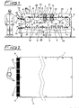
fig. 1 shows the structural layout of an example of cleaning machine for tubes for supporting long alimentary pastas, configured with horizontal arrangement and dual cleaning unit, -
fig. 2 shows the plan view of the same machine offigure 1 , -
fig. 3 shows an exemplifying partial increased scale view of a machine with vertical arrangement, wherein a single cleaning unit is shown, not limiting, associated to conveyors connected to automatic loading and unloading means of the tubes supporting the long pastas, and -
fig. 4 - a, b shows, only by way of an example of the invention and of the operation thereof, the schematic perspective, partial view and the side view of a traditional "tube" supporting long pastas. - With reference to
figures 1 and 2 , the cleaning machine is configured, according to a horizontal development solution thereof, with a box-shaped structure 1 whose top part is divided into sequential sectors or stages through which the horizontal feeding branches of two motor-drivenparallel side conveyors 2 slide at the top thereof, stepping-wise, on which twoconsecutive washing stages 3 are transversally aligned, and in a substantially tangent direction, each consisting of parallel pairs of motor-drivenroll brushes 4. - The
parallel conveyors 2 are generically chain-type withtoothed wheel coupling 5, withmotor 6, and themeshes 7 thereof compriseintermediate slots 8 wherein theend pins 9 oftubes 10 supporting the long pastas to be dried 11 and to be subjected to the cleaning treatment, engage automatically during the movement of the conveyors themselves. In a more inexpensive version,tubes 10 can be manually loaded, through a top cross opening 12 of the box-shaped structure 1, with progressive arrangement one after the other in a reciprocal support, on an inclinedinlet chute loader 13 which is arranged in tangent alignment relation with the start of the feeding branches ofconveyors 2; the loadedtubes 10 slide by their own weight downwards until theirend pins 9 come into contact with themeshes 7 of the sideparallel conveyors 2, come into engagement relation in the correspondingintermediate slots 8 and are pulled in a circle for cleaning. On the same side, through a bottom opening 14 of thesame structure 1 and withoutlet chute 15, the tubes after the cleaning treatment are unloaded outwards and manually picked up for being reused on the production lines of long pastas. -
Casings conveyors 2, withoutlets 18 for collecting and discharging the residues of solids removed from the various steps of cleaning and of detergent products. In a sequence, starting from the first stage A wherein theend pins 9 oftubes 10 engage in theintermediate slots 8 ofmeshes 7 ofconveyors 2, the tubes themselves are sprinkled with steam passing belowsprayers 19; in the next stage B, throughsprayers 20 the tubes are subject to a soaking step with water or steam with or without detergent; in stages C and D the tubes are subject in a sequence to brushing with injection ofdetergent 21 and brushing with injection ofwater 22 for removing the detergents, by said parallel pairs ofroll brushes 4; in stage E,sprayers 23 carry out a rinsing with water, and drainage. After that, along the return path ofconveyors 2, the rinsedtubes 10 move on to a drying stage F with forcedair 24 and an optional subsequent stage G ofatomisation 25 with alimentary oil, to then be discharged outwards through the bottom opening 14 withoutlet chute 15. - In the solution shown, the inlet and outlet of the
tubes 10 are arranged on the same side of the machine; it is clear that in case of particular system requirements, the inlet and the outlet can also be arranged in different positions, such as at the opposite ends, by simply changing the position of stages F and G, changing the path ofconveyors 2 and suitably varying the one and the other depending on the specific system requirements, as a whole. - It should be noted that for the same approximately ogive-like configuration tapered downwards 26 of the cross section of
tubes 10 and due to the fact that the relativeside support pins 9 are arranged at the larger end of the same sections, the tubes tend to remain in the vertical position conceived for the "astride" support of long pastas, as they can oscillate aboutpins 9 themselves; the tubes remain in the same position also during the cleaning cycle so as to facilitate the steps of drainage and free drop downwards of the solid particles to be removed and of the detergent fluids. Only during the steps of cleaning withroll brushes 4 andatomisation 25 with alimentary oil, they are necessarily temporarily bent to horizontal position byguides 27. - By analogy with the above description, and with the same function, the machine according to the invention can also be developed in vertical direction, depending on the space available around the production systems of long pastas;
figure 3 shows a synthesis of such solution wherein thetubes 10 remain hanging on themeshes 7 ofconveyors 2 always in vertical position as desired and for the purposes indicated above, and the cleaning units with theroll brushes 4 andrelative sprayers - The same
figure 3 further shows an example of automatic system for loading and unloading thetubes 10 which can in any case be adopted both for horizontal arrangement and for vertical arrangement machines. In this case, an automatically controlledbaffle 28 is applied at the end of each treatment cycle, after the total drying and the unloading ofpastas 11, on thereturn line 29 of thetubes 10 and of course, before they are resent to a new working cycle. Baffle 28 operates by deviating thetubes 10, in progressive alignment, one after the other in reciprocal support, on the inclinedinlet chute loader 13 which passes through the top cross opening 12, up to the connection of the tubes themselves on themeshes 7 of the conveyors. In the unloading step, a pair ofauxiliary conveyors 30 directly hooks theside pins 9 of theclean tubes 10 arriving from the return path of saidconveyors 2 and sends them to the reintroduction on thesame line 29 of the treatment cycle of thepastes 11; otherwise the same pair ofauxiliary conveyors 30 can hook theside pins 9 arriving from the discharge through the bottom opening 14 of thesame structure 1 and saidoutlet chute 15. - According to what described and illustrated, the cleaning machine for tubes for supporting long
alimentary pastas 11, according to the invention, can be constructed with the same functions and for the same purpose, with horizontal or vertical orientation of theconveyors 2 and of all the process stages, with loading and unloading of the tubes of manual type or automatic type, on one side only or on different sides, with one ormore brushing stages 4 associated to water and/or detergent and/ore mixture injections, for the application in association with new or existing systems for producing long pasta with suitable sizing and configurations, depending on the useful and/or available spaces and on the specific requirements.
Claims (11)
- A machine for cleaning long alimentary pastas supporting tubes (10) provided with end pins (9), said tubes (10) being configured with an ogive-like upturned drop section with said support pins (9) protruding at the larger end of the section, the cleaning machine comprising an enclosure in the shape of a box structure (1) that receives therein:- a pair of parallel conveyors (2) for carrying said tubes (10) along a path inside of said structure (1), said conveyor path comprising a feeding branch and a return branch, the parallel conveyors comprising conveyor meshes (7) with intermediate slots (8) in which the end pins (9) of the tubes (10) engage and whereby the engaged tubes (10) can oscillate about said pins (9),- means for loading/unloading (12, 14) the tubes (10) to be cleaned into the machine;- cleaning and washing stations (A, B) with sprayers (19) of steam and (20) of water and steam for soaking with detergents;- at least one cleaning station (C, D) consisting of pairs of parallel roll brushes (4) associated to sprayers (21, 22) of hot water and/or detergent fluids and/or mixtures;- sequential stations of rinsing (E) and drying (F), and- an atomisation station (G) for spraying an alimentary oil over said cleaned tubes arranged within said structure (1).
- A machine (10) as claimed in claim 1, characterised in that said conveyor path comprises reversing means (5) between said feeding branch and a return branch whereby said means for loading/unloading (12, 14) the tubes (10) to be cleaned are located on the same side of said enclosure (1), and in that said atomisation stage (G) further comprises guides (27) for temporarily positioning said tubes to a horizontal position.
- A machine as claimed in claim 1 or 2, characterised in that said cleaning and washing stages (A, B) have vertical orientation.
- A machine as claimed in claim 1 or 2, characterised in that said cleaning and washing stages (A, B) have horizontal orientation.
- A machine as claimed in claim 3 or 4, characterised in that said means for loading the tubes (10) to be cleaned comprise a manual loading system (12) and a manual unloading system (14).
- A machine as claimed in claim 5, characterised in that said manual loading system (12) comprises an inclined inlet chute loader (13), which passes through a cross opening (12) of said box-shaped structure (1) up to arrange in alignment contiguous to the intermediate slots (8) of the meshes (7) according to the feeding path of said conveyors (2); said tubes (10) being progressively loaded, one after the other in reciprocal support, on said inclined inlet chute (13) and come into direct and sequential connection relation with the mating end pins (9), in the above slots (8).
- A machine as claimed in claim 5 or 6, characterised in that said manual unloading system (14) of the cleaned tubes (10) comprises an inclined outlet chute (15), aligned and contiguous to the intermediate slots (8) of the meshes (7) according to the return path of said conveyors (2) and extended outwards of said box-shaped structure (1).
- A machine as claimed in claim 3 or 4, characterised in that said means for loading the tubes (10) to be cleaned comprise an automatic loading system and an automatic unloading system.
- A machine as claimed in claim 8, characterised in that said automatic loading system for the tubes (10) to be cleaned comprises an automatically controlled baffle (28), applied on the return line (29) of said tubes (10), at the end of each cycle, after the total drying and discharge of the pastes (11) and before they are sent to a new working cycle; said baffle (28) being associated to an inclined inlet chute loader (13), which passes through a cross opening (12) of said box-shaped structure (1) up to arrange in alignment contiguous to the intermediate slots (8) of the meshes (7) according to the feeding path of said conveyors (2); said tubes (10) being progressively loaded, one after the other in reciprocal support, on said inclined inlet chute (13) and come into direct and sequential connection relation, with the mating end pins (9), in the above slots (8).
- A machine as claimed in claim 8 or 9, characterised in that said automatic unloading system of the cleaned tubes (10) comprises an inclined outlet chute (15), aligned and contiguous to the intermediate slots (8) of the meshes (7) according to the return path of said conveyors (2) and extending outwards of said box-shaped structure (1), which chute (15) is associated to a pair of auxiliary conveyors (30) which hooks the side pins (9) of the clean unloaded tubes (10) and sends them to the reintroduction on said line (29) of said paste treatment cycle (11) and in that said automatic system for unloading the clean tubes (10) comprises a pair of auxiliary conveyors (29) which hooks and picks up the side pins (9) of the clean tubes (10) present in the intermediate slots (8) of the meshes (7) that arrive from the return path of said conveyors (2) and directly sends them to the reintroduction on the same line (28) of the paste treatment cycle (11).
- A machine as claimed in claims 1 to 6, characterised in that said cleaning and washing stages (A, B) comprise steam sprayers (19), sprayers for soaking and for detergent substances (20); in that said at least one cleaning stage (C and/or D) comprises a brushing and removal unit consisting of parallel pairs of roll brushes (4) associated to injectors (21 and/or 22) of water and/or detergents and/or mixtures; in that said rinsing stage (E) comprises sprayers (23); in that said drying stage (F) is with forced air.
Applications Claiming Priority (1)
| Application Number | Priority Date | Filing Date | Title |
|---|---|---|---|
| IT000156A ITRE20060156A1 (en) | 2006-12-20 | 2006-12-20 | CLEANING MACHINE FOR RODS FOR SUPPORTING LONG FOOD PASTA. |
Publications (3)
| Publication Number | Publication Date |
|---|---|
| EP1935513A2 EP1935513A2 (en) | 2008-06-25 |
| EP1935513A3 EP1935513A3 (en) | 2009-05-13 |
| EP1935513B1 true EP1935513B1 (en) | 2011-08-31 |
Family
ID=39156571
Family Applications (1)
| Application Number | Title | Priority Date | Filing Date |
|---|---|---|---|
| EP07012564A Active EP1935513B1 (en) | 2006-12-20 | 2007-06-27 | Cleaning machine for tubes supporting long alimentary pastas |
Country Status (4)
| Country | Link |
|---|---|
| EP (1) | EP1935513B1 (en) |
| AT (1) | ATE522284T1 (en) |
| ES (1) | ES2372583T3 (en) |
| IT (1) | ITRE20060156A1 (en) |
Families Citing this family (5)
| Publication number | Priority date | Publication date | Assignee | Title |
|---|---|---|---|---|
| FR3077745B1 (en) * | 2018-02-15 | 2021-01-08 | Gsf Groupe Services France | CLEANING PROCESS IN THE FOOD INDUSTRY |
| WO2020222163A1 (en) * | 2019-04-30 | 2020-11-05 | Kothari Rinku Kumari | Multistation apparatus for cleaning inner and outside surfaces of cylinder halves |
| CN111151484A (en) * | 2020-01-19 | 2020-05-15 | 富士智能机电(珠海)有限公司 | Brush-grinding type automatic cleaning device |
| CN111570376A (en) * | 2020-06-22 | 2020-08-25 | 阿布都司拉木·阿布都艾尼 | Toilet paper washing machine |
| CN112110374B (en) * | 2020-10-16 | 2022-04-19 | 河南中烟工业有限责任公司 | Moving lifting type full-automatic cleaning method for conveying belt |
Family Cites Families (4)
| Publication number | Priority date | Publication date | Assignee | Title |
|---|---|---|---|---|
| DE3506556A1 (en) * | 1985-02-25 | 1986-09-04 | Oscar von 3008 Garbsen Wedekind | Process and device for cleaning flat small parts, in particular coins |
| DE19509256C2 (en) | 1995-03-08 | 1998-07-16 | Estermann Simon Boris | Device for cleaning bowl-shaped lamp glasses |
| CH690056A5 (en) | 1996-02-09 | 2000-04-14 | Nestle Sa | pasta drying bar. |
| US20050273955A1 (en) * | 2004-06-11 | 2005-12-15 | Rogus Thomas E | Bar stock degreasing machine |
-
2006
- 2006-12-20 IT IT000156A patent/ITRE20060156A1/en unknown
-
2007
- 2007-06-27 ES ES07012564T patent/ES2372583T3/en active Active
- 2007-06-27 EP EP07012564A patent/EP1935513B1/en active Active
- 2007-06-27 AT AT07012564T patent/ATE522284T1/en not_active IP Right Cessation
Also Published As
| Publication number | Publication date |
|---|---|
| ES2372583T3 (en) | 2012-01-24 |
| ATE522284T1 (en) | 2011-09-15 |
| EP1935513A3 (en) | 2009-05-13 |
| EP1935513A2 (en) | 2008-06-25 |
| ITRE20060156A1 (en) | 2008-06-21 |
Similar Documents
| Publication | Publication Date | Title |
|---|---|---|
| EP1935513B1 (en) | Cleaning machine for tubes supporting long alimentary pastas | |
| CN106766690B (en) | Turnround basket dehydration device and Turnround basket cleaning dewaterer | |
| CN210492539U (en) | Longan cleaning equipment is used in dried longan production and processing | |
| CN207563334U (en) | For the automatic rinser of auto parts and components | |
| KR20090118168A (en) | Automatic washing machine for table-ware of group feeding | |
| CN108033232A (en) | A kind of multipurpose barrel conveyer | |
| KR20140082009A (en) | Auto washing machine assembly with transfer conveyor | |
| CN210394605U (en) | Spinneret plate self-cleaning device | |
| CN210960340U (en) | Automatic fruit and vegetable cleaning processing production line | |
| CN108246709B (en) | Deoiling cleaning system | |
| JP2019000782A (en) | Vacuum filtration apparatus and vacuum filtration method | |
| CN106580215A (en) | Novel full-automatic turning dish-washing machine | |
| CN106216475A (en) | Integrated machine system is cleaned in a kind of punching press | |
| US2461162A (en) | Can washing machine | |
| JP6971336B2 (en) | Vacuum filtration method | |
| KR101052751B1 (en) | Automatic dishwasher | |
| KR200149265Y1 (en) | Semiautomatic segregating unit of tableware | |
| CN211134807U (en) | Integrated cleaning machine | |
| CN209376582U (en) | A kind of automatic fishing meat production line | |
| US3273573A (en) | Dishwashing machine and refuse disposal and method | |
| CN209953347U (en) | Automatic change ultrasonic cleaning equipment | |
| CN112754385A (en) | Robot intelligent dish washer | |
| CN206466570U (en) | A kind of pipeline system seafood processing system | |
| CN110813882A (en) | Intelligent cleaning line for multiple mechanical parts | |
| CN105363707A (en) | Cleaning device of oil-filter screen chain for fried peanuts |
Legal Events
| Date | Code | Title | Description |
|---|---|---|---|
| PUAI | Public reference made under article 153(3) epc to a published international application that has entered the european phase |
Free format text: ORIGINAL CODE: 0009012 |
|
| AK | Designated contracting states |
Kind code of ref document: A2 Designated state(s): AT BE BG CH CY CZ DE DK EE ES FI FR GB GR HU IE IS IT LI LT LU LV MC MT NL PL PT RO SE SI SK TR |
|
| AX | Request for extension of the european patent |
Extension state: AL BA HR MK RS |
|
| PUAL | Search report despatched |
Free format text: ORIGINAL CODE: 0009013 |
|
| AK | Designated contracting states |
Kind code of ref document: A3 Designated state(s): AT BE BG CH CY CZ DE DK EE ES FI FR GB GR HU IE IS IT LI LT LU LV MC MT NL PL PT RO SE SI SK TR |
|
| AX | Request for extension of the european patent |
Extension state: AL BA HR MK RS |
|
| 17P | Request for examination filed |
Effective date: 20091103 |
|
| AKX | Designation fees paid |
Designated state(s): AT BE BG CH CY CZ DE DK EE ES FI FR GB GR HU IE IS IT LI LT LU LV MC MT NL PL PT RO SE SI SK TR |
|
| 17Q | First examination report despatched |
Effective date: 20110217 |
|
| GRAP | Despatch of communication of intention to grant a patent |
Free format text: ORIGINAL CODE: EPIDOSNIGR1 |
|
| GRAS | Grant fee paid |
Free format text: ORIGINAL CODE: EPIDOSNIGR3 |
|
| GRAA | (expected) grant |
Free format text: ORIGINAL CODE: 0009210 |
|
| AK | Designated contracting states |
Kind code of ref document: B1 Designated state(s): AT BE BG CH CY CZ DE DK EE ES FI FR GB GR HU IE IS IT LI LT LU LV MC MT NL PL PT RO SE SI SK TR |
|
| REG | Reference to a national code |
Ref country code: GB Ref legal event code: FG4D Ref country code: CH Ref legal event code: EP |
|
| REG | Reference to a national code |
Ref country code: IE Ref legal event code: FG4D |
|
| REG | Reference to a national code |
Ref country code: DE Ref legal event code: R096 Ref document number: 602007016671 Country of ref document: DE Effective date: 20111124 |
|
| REG | Reference to a national code |
Ref country code: NL Ref legal event code: VDEP Effective date: 20110831 |
|
| REG | Reference to a national code |
Ref country code: ES Ref legal event code: FG2A Ref document number: 2372583 Country of ref document: ES Kind code of ref document: T3 Effective date: 20120124 |
|
| LTIE | Lt: invalidation of european patent or patent extension |
Effective date: 20110831 |
|
| PG25 | Lapsed in a contracting state [announced via postgrant information from national office to epo] |
Ref country code: LT Free format text: LAPSE BECAUSE OF FAILURE TO SUBMIT A TRANSLATION OF THE DESCRIPTION OR TO PAY THE FEE WITHIN THE PRESCRIBED TIME-LIMIT Effective date: 20110831 Ref country code: FI Free format text: LAPSE BECAUSE OF FAILURE TO SUBMIT A TRANSLATION OF THE DESCRIPTION OR TO PAY THE FEE WITHIN THE PRESCRIBED TIME-LIMIT Effective date: 20110831 Ref country code: NL Free format text: LAPSE BECAUSE OF FAILURE TO SUBMIT A TRANSLATION OF THE DESCRIPTION OR TO PAY THE FEE WITHIN THE PRESCRIBED TIME-LIMIT Effective date: 20110831 Ref country code: SE Free format text: LAPSE BECAUSE OF FAILURE TO SUBMIT A TRANSLATION OF THE DESCRIPTION OR TO PAY THE FEE WITHIN THE PRESCRIBED TIME-LIMIT Effective date: 20110831 Ref country code: IS Free format text: LAPSE BECAUSE OF FAILURE TO SUBMIT A TRANSLATION OF THE DESCRIPTION OR TO PAY THE FEE WITHIN THE PRESCRIBED TIME-LIMIT Effective date: 20111231 |
|
| REG | Reference to a national code |
Ref country code: AT Ref legal event code: MK05 Ref document number: 522284 Country of ref document: AT Kind code of ref document: T Effective date: 20110831 |
|
| PG25 | Lapsed in a contracting state [announced via postgrant information from national office to epo] |
Ref country code: AT Free format text: LAPSE BECAUSE OF FAILURE TO SUBMIT A TRANSLATION OF THE DESCRIPTION OR TO PAY THE FEE WITHIN THE PRESCRIBED TIME-LIMIT Effective date: 20110831 Ref country code: GR Free format text: LAPSE BECAUSE OF FAILURE TO SUBMIT A TRANSLATION OF THE DESCRIPTION OR TO PAY THE FEE WITHIN THE PRESCRIBED TIME-LIMIT Effective date: 20111201 Ref country code: LV Free format text: LAPSE BECAUSE OF FAILURE TO SUBMIT A TRANSLATION OF THE DESCRIPTION OR TO PAY THE FEE WITHIN THE PRESCRIBED TIME-LIMIT Effective date: 20110831 Ref country code: SI Free format text: LAPSE BECAUSE OF FAILURE TO SUBMIT A TRANSLATION OF THE DESCRIPTION OR TO PAY THE FEE WITHIN THE PRESCRIBED TIME-LIMIT Effective date: 20110831 Ref country code: CY Free format text: LAPSE BECAUSE OF FAILURE TO SUBMIT A TRANSLATION OF THE DESCRIPTION OR TO PAY THE FEE WITHIN THE PRESCRIBED TIME-LIMIT Effective date: 20110831 |
|
| PG25 | Lapsed in a contracting state [announced via postgrant information from national office to epo] |
Ref country code: BE Free format text: LAPSE BECAUSE OF FAILURE TO SUBMIT A TRANSLATION OF THE DESCRIPTION OR TO PAY THE FEE WITHIN THE PRESCRIBED TIME-LIMIT Effective date: 20110831 |
|
| PG25 | Lapsed in a contracting state [announced via postgrant information from national office to epo] |
Ref country code: CZ Free format text: LAPSE BECAUSE OF FAILURE TO SUBMIT A TRANSLATION OF THE DESCRIPTION OR TO PAY THE FEE WITHIN THE PRESCRIBED TIME-LIMIT Effective date: 20110831 Ref country code: SK Free format text: LAPSE BECAUSE OF FAILURE TO SUBMIT A TRANSLATION OF THE DESCRIPTION OR TO PAY THE FEE WITHIN THE PRESCRIBED TIME-LIMIT Effective date: 20110831 |
|
| PG25 | Lapsed in a contracting state [announced via postgrant information from national office to epo] |
Ref country code: EE Free format text: LAPSE BECAUSE OF FAILURE TO SUBMIT A TRANSLATION OF THE DESCRIPTION OR TO PAY THE FEE WITHIN THE PRESCRIBED TIME-LIMIT Effective date: 20110831 Ref country code: PL Free format text: LAPSE BECAUSE OF FAILURE TO SUBMIT A TRANSLATION OF THE DESCRIPTION OR TO PAY THE FEE WITHIN THE PRESCRIBED TIME-LIMIT Effective date: 20110831 Ref country code: PT Free format text: LAPSE BECAUSE OF FAILURE TO SUBMIT A TRANSLATION OF THE DESCRIPTION OR TO PAY THE FEE WITHIN THE PRESCRIBED TIME-LIMIT Effective date: 20120102 Ref country code: RO Free format text: LAPSE BECAUSE OF FAILURE TO SUBMIT A TRANSLATION OF THE DESCRIPTION OR TO PAY THE FEE WITHIN THE PRESCRIBED TIME-LIMIT Effective date: 20110831 |
|
| PG25 | Lapsed in a contracting state [announced via postgrant information from national office to epo] |
Ref country code: DK Free format text: LAPSE BECAUSE OF FAILURE TO SUBMIT A TRANSLATION OF THE DESCRIPTION OR TO PAY THE FEE WITHIN THE PRESCRIBED TIME-LIMIT Effective date: 20110831 |
|
| PLBE | No opposition filed within time limit |
Free format text: ORIGINAL CODE: 0009261 |
|
| STAA | Information on the status of an ep patent application or granted ep patent |
Free format text: STATUS: NO OPPOSITION FILED WITHIN TIME LIMIT |
|
| 26N | No opposition filed |
Effective date: 20120601 |
|
| REG | Reference to a national code |
Ref country code: DE Ref legal event code: R097 Ref document number: 602007016671 Country of ref document: DE Effective date: 20120601 |
|
| PG25 | Lapsed in a contracting state [announced via postgrant information from national office to epo] |
Ref country code: MC Free format text: LAPSE BECAUSE OF NON-PAYMENT OF DUE FEES Effective date: 20120630 |
|
| REG | Reference to a national code |
Ref country code: CH Ref legal event code: PL |
|
| REG | Reference to a national code |
Ref country code: CH Ref legal event code: PL |
|
| GBPC | Gb: european patent ceased through non-payment of renewal fee |
Effective date: 20120627 |
|
| REG | Reference to a national code |
Ref country code: IE Ref legal event code: MM4A |
|
| PG25 | Lapsed in a contracting state [announced via postgrant information from national office to epo] |
Ref country code: LI Free format text: LAPSE BECAUSE OF NON-PAYMENT OF DUE FEES Effective date: 20120630 Ref country code: CH Free format text: LAPSE BECAUSE OF NON-PAYMENT OF DUE FEES Effective date: 20120630 Ref country code: IE Free format text: LAPSE BECAUSE OF NON-PAYMENT OF DUE FEES Effective date: 20120627 Ref country code: GB Free format text: LAPSE BECAUSE OF NON-PAYMENT OF DUE FEES Effective date: 20120627 |
|
| PG25 | Lapsed in a contracting state [announced via postgrant information from national office to epo] |
Ref country code: BG Free format text: LAPSE BECAUSE OF FAILURE TO SUBMIT A TRANSLATION OF THE DESCRIPTION OR TO PAY THE FEE WITHIN THE PRESCRIBED TIME-LIMIT Effective date: 20111130 |
|
| PG25 | Lapsed in a contracting state [announced via postgrant information from national office to epo] |
Ref country code: MT Free format text: LAPSE BECAUSE OF FAILURE TO SUBMIT A TRANSLATION OF THE DESCRIPTION OR TO PAY THE FEE WITHIN THE PRESCRIBED TIME-LIMIT Effective date: 20110831 |
|
| PG25 | Lapsed in a contracting state [announced via postgrant information from national office to epo] |
Ref country code: TR Free format text: LAPSE BECAUSE OF FAILURE TO SUBMIT A TRANSLATION OF THE DESCRIPTION OR TO PAY THE FEE WITHIN THE PRESCRIBED TIME-LIMIT Effective date: 20110831 |
|
| PG25 | Lapsed in a contracting state [announced via postgrant information from national office to epo] |
Ref country code: LU Free format text: LAPSE BECAUSE OF NON-PAYMENT OF DUE FEES Effective date: 20120627 |
|
| PG25 | Lapsed in a contracting state [announced via postgrant information from national office to epo] |
Ref country code: HU Free format text: LAPSE BECAUSE OF FAILURE TO SUBMIT A TRANSLATION OF THE DESCRIPTION OR TO PAY THE FEE WITHIN THE PRESCRIBED TIME-LIMIT Effective date: 20070627 |
|
| REG | Reference to a national code |
Ref country code: FR Ref legal event code: PLFP Year of fee payment: 10 |
|
| REG | Reference to a national code |
Ref country code: FR Ref legal event code: PLFP Year of fee payment: 11 |
|
| REG | Reference to a national code |
Ref country code: FR Ref legal event code: PLFP Year of fee payment: 12 |
|
| PGFP | Annual fee paid to national office [announced via postgrant information from national office to epo] |
Ref country code: FR Payment date: 20230622 Year of fee payment: 17 Ref country code: DE Payment date: 20230627 Year of fee payment: 17 |
|
| PGFP | Annual fee paid to national office [announced via postgrant information from national office to epo] |
Ref country code: IT Payment date: 20230622 Year of fee payment: 17 Ref country code: ES Payment date: 20230720 Year of fee payment: 17 |