EP1933548A2 - Vorrichtung zur Videosignalverarbeitung und Verfahren zur Videosignalverarbeitung - Google Patents
Vorrichtung zur Videosignalverarbeitung und Verfahren zur Videosignalverarbeitung Download PDFInfo
- Publication number
- EP1933548A2 EP1933548A2 EP07020140A EP07020140A EP1933548A2 EP 1933548 A2 EP1933548 A2 EP 1933548A2 EP 07020140 A EP07020140 A EP 07020140A EP 07020140 A EP07020140 A EP 07020140A EP 1933548 A2 EP1933548 A2 EP 1933548A2
- Authority
- EP
- European Patent Office
- Prior art keywords
- video signal
- histogram
- level
- unit
- processing device
- Prior art date
- Legal status (The legal status is an assumption and is not a legal conclusion. Google has not performed a legal analysis and makes no representation as to the accuracy of the status listed.)
- Withdrawn
Links
Images


Classifications
-
- G—PHYSICS
- G06—COMPUTING OR CALCULATING; COUNTING
- G06T—IMAGE DATA PROCESSING OR GENERATION, IN GENERAL
- G06T5/00—Image enhancement or restoration
- G06T5/40—Image enhancement or restoration using histogram techniques
-
- G—PHYSICS
- G06—COMPUTING OR CALCULATING; COUNTING
- G06F—ELECTRIC DIGITAL DATA PROCESSING
- G06F3/00—Input arrangements for transferring data to be processed into a form capable of being handled by the computer; Output arrangements for transferring data from processing unit to output unit, e.g. interface arrangements
- G06F3/14—Digital output to display device ; Cooperation and interconnection of the display device with other functional units
-
- G—PHYSICS
- G06—COMPUTING OR CALCULATING; COUNTING
- G06T—IMAGE DATA PROCESSING OR GENERATION, IN GENERAL
- G06T5/00—Image enhancement or restoration
- G06T5/90—Dynamic range modification of images or parts thereof
- G06T5/92—Dynamic range modification of images or parts thereof based on global image properties
-
- H—ELECTRICITY
- H04—ELECTRIC COMMUNICATION TECHNIQUE
- H04N—PICTORIAL COMMUNICATION, e.g. TELEVISION
- H04N21/00—Selective content distribution, e.g. interactive television or video on demand [VOD]
- H04N21/40—Client devices specifically adapted for the reception of or interaction with content, e.g. set-top-box [STB]; Operations thereof
- H04N21/43—Processing of content or additional data, e.g. demultiplexing additional data from a digital video stream; Elementary client operations, e.g. monitoring of home network or synchronising decoder's clock; Client middleware
- H04N21/431—Generation of visual interfaces for content selection or interaction; Content or additional data rendering
- H04N21/4318—Generation of visual interfaces for content selection or interaction; Content or additional data rendering by altering the content in the rendering process, e.g. blanking, blurring or masking an image region
-
- H—ELECTRICITY
- H04—ELECTRIC COMMUNICATION TECHNIQUE
- H04N—PICTORIAL COMMUNICATION, e.g. TELEVISION
- H04N21/00—Selective content distribution, e.g. interactive television or video on demand [VOD]
- H04N21/40—Client devices specifically adapted for the reception of or interaction with content, e.g. set-top-box [STB]; Operations thereof
- H04N21/43—Processing of content or additional data, e.g. demultiplexing additional data from a digital video stream; Elementary client operations, e.g. monitoring of home network or synchronising decoder's clock; Client middleware
- H04N21/44—Processing of video elementary streams, e.g. splicing a video clip retrieved from local storage with an incoming video stream or rendering scenes according to encoded video stream scene graphs
- H04N21/44008—Processing of video elementary streams, e.g. splicing a video clip retrieved from local storage with an incoming video stream or rendering scenes according to encoded video stream scene graphs involving operations for analysing video streams, e.g. detecting features or characteristics in the video stream
-
- H—ELECTRICITY
- H04—ELECTRIC COMMUNICATION TECHNIQUE
- H04N—PICTORIAL COMMUNICATION, e.g. TELEVISION
- H04N5/00—Details of television systems
- H04N5/14—Picture signal circuitry for video frequency region
- H04N5/16—Circuitry for reinsertion of DC and slowly varying components of signal; Circuitry for preservation of black or white level
- H04N5/165—Circuitry for reinsertion of DC and slowly varying components of signal; Circuitry for preservation of black or white level to maintain the black level constant
-
- H—ELECTRICITY
- H04—ELECTRIC COMMUNICATION TECHNIQUE
- H04N—PICTORIAL COMMUNICATION, e.g. TELEVISION
- H04N5/00—Details of television systems
- H04N5/44—Receiver circuitry for the reception of television signals according to analogue transmission standards
- H04N5/57—Control of contrast or brightness
-
- G—PHYSICS
- G06—COMPUTING OR CALCULATING; COUNTING
- G06T—IMAGE DATA PROCESSING OR GENERATION, IN GENERAL
- G06T2207/00—Indexing scheme for image analysis or image enhancement
- G06T2207/10—Image acquisition modality
- G06T2207/10016—Video; Image sequence
-
- G—PHYSICS
- G09—EDUCATION; CRYPTOGRAPHY; DISPLAY; ADVERTISING; SEALS
- G09G—ARRANGEMENTS OR CIRCUITS FOR CONTROL OF INDICATING DEVICES USING STATIC MEANS TO PRESENT VARIABLE INFORMATION
- G09G2320/00—Control of display operating conditions
- G09G2320/02—Improving the quality of display appearance
- G09G2320/0233—Improving the luminance or brightness uniformity across the screen
-
- G—PHYSICS
- G09—EDUCATION; CRYPTOGRAPHY; DISPLAY; ADVERTISING; SEALS
- G09G—ARRANGEMENTS OR CIRCUITS FOR CONTROL OF INDICATING DEVICES USING STATIC MEANS TO PRESENT VARIABLE INFORMATION
- G09G2320/00—Control of display operating conditions
- G09G2320/02—Improving the quality of display appearance
- G09G2320/0238—Improving the black level
Definitions
- One embodiment of the invention relates to a video signal processing device and a video signal processing method, and more particularly to a video signal processing device and video signal processing method capable of correcting the histogram according to the set-up level of an input video signal.
- a video signal processing device which processes a histogram data corresponding to a brightness of an input video signal and corrects a gray scale of an output video signal based on the processing result, is disclosed by, for example, Japanese Patent No. 2512562 .
- the video signal processing device includes a histogram memory which temporarily stores the histogram data corresponding to the brightness of an input video signal and a histogram processing unit which processes the histogram data.
- the histogram processing unit detects histogram information such as an average value, mode value, maximum value, minimum value, difference coefficient, black area, white area, etc. from the histogram data in histogram averaging processing for extending the dynamic range of an output video signal. And, the histogram processing unit creates the corrected histogram data on the basis of these values.
- original histogram data are corrected on the basis of the above histogram information so that correction of the output video signal optimized for the input video signal can be done.
- the correction for example, it is possible to prevent the dynamic range of the output video signal from being excessively extended and correct the gray scale over the entire brightness range thereof.
- the voltage level representative of black of an input video signal differs according to the standard such as the signal of NTSC or NTSC-J. Therefore, in the histogram processing unit in which the set-up level is optimized for, e.g. the NTSC-J having the set-up level of OIRE (Institute of Radio Engineers), where it receives the NTSC signal having the set-up level of 7.5 IRE, for the NTSC-J, the histogram data will be shifted toward a high brightness state, i.e. becomes the histogram data with no histogram in a black signal zone. As a result, the optimum correction of the histogram data, and hence the optimum gray scale correction of the output video signal may not be done.
- OIRE Institute of Radio Engineers
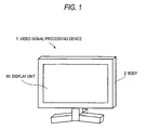
- Fig. 1 is an exemplary schematic diagram showing the external appearance of a video signal processing device according to a first embodiment
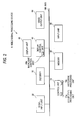
- Fig. 2 is an exemplary block diagram showing a configuration of the video signal processing device according to the first embodiment
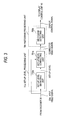
- Fig. 3 is an exemplary block diagram showing a configuration of a set-up level processing unit and a histogram processing unit according to the first embodiment
- Figs. 4A to 4C are exemplary graphs showing an operation of the video signal processing device according to the first embodiment
- Figs. 5A to 5F are exemplary graphs showing an operation of a backlight control unit in the first embodiment
- Fig. 6 is an exemplary block diagram showing a configuration of the set-up level processing unit and the histogram processing unit according to a second embodiment
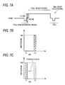
- Figs. 7A to 7C are exemplary graphs showing an operation of the video signal processing device according to the second embodiment.
- a video signal processing device includes a set-up level detecting unit that detects a set-up level of an input video signal, a set-up level correcting unit that corrects the set-up level of the input video signal, and a histogram detecting unit that detects a histogram corresponding to a brightness of a video signal output from the set-up level correcting unit.
- a video signal processing device includes a histogram detecting unit that detects a histogram corresponding to a brightness of an input video signal, a set-up level detecting unit that detects a set-up level of the input video signal, the set-up level detecting unit outputting a histogram-correction controlling signal for correcting the histogram based on the set-up level, and a histogram correcting unit that corrects the histogram based on the histogram-correction controlling signal output from the set-up level detecting unit.
- a video signal processing method includes detecting a set-up level of an input video signal, correcting the set-up level of the input video signal, outputting a corrected video signal based on the correction, and detecting a histogram corresponding to a brightness of the corrected video signal.
- Fig. 1 is an exemplary schematic diagram showing the external appearance of a video signal processing device according to a first embodiment of this invention.
- a video signal processing device 1 incorporates electronic components corresponding to the image processing such as a tuner or decoder inside a body 2. Inside the body 2, the video signal processing device 1 processes a video signal received from the outside, which is outputted from a display unit 50.
- the display unit 50 may be e.g. an LCD (Liquid Crystal Display).
- Fig. 2 is an exemplary block diagram showing the configuration of a video signal processing device according to the first embodiment of this invention.
- a video signal processing device 1 includes a signal input unit 20 for receiving a tuner input signal demodulated from a video signal of a broadcasting radio wave received through an outside antenna and a video/audio input signal received from e.g. an external play-back machine; a decoder 30 for decoding the output received from the signal input unit 20 to output an input video signal and an input audio signal; a display control unit 40 for receiving the input video signal output from the decoder 30 and outputting an output video signal with the display controlled for the brightness and contrast; a display unit (LCD) 50 for displaying the output video signal output from the display control unit 40; a voice output unit 60 for outputting the audio signal received from the decoder 30 as a voice; a control unit 70 for controlling the respective units within the video signal processing device 1; a memory 80 for temporarily storing the data being processed by the control unit 70; an input unit 90 equipped with an input device consisting of a plurality of switches not shown; and a bus 100 connecting the respective units within the video signal processing device 1.
- the control unit 70 incorporates a set-up level processing unit 70a for detecting and correcting the set-up level which is the voltage level representative of black of the input video signal output from the decoder 30, and a histogram processing unit 70b for detecting and correcting the histogram corresponding to the brightness of the input video signal.
- the display control unit 40 incorporates a backlight control unit 40a for controlling the backlight of the display unit 50 which is LCD.
- the backlight control unit 40a operates on the basis of the detection result in the histogram processing unit 70b.
- Fig. 3 is an exemplary block diagram showing the configuration of the set-up level processing unit 70a and histogram processing unit 70b according to the first embodiment of the invention.
- the set-up level processing 70a incorporates a set-up level detecting unit 700a for detecting the set-up level of an input video signal 30A output from the decoder 30 and a set-up level correcting unit 701a for correcting the set-up level of the input video signal on the basis of the detection result in the set-up level detecting unit 700a.
- the histogram processing unit 70b incorporates a histogram detecting unit 700b for receiving the corrected signal corrected in the set-up level correcting unit 701a to compute the distribution of the frequency corresponding to the brightness of the correction signal.
- the detection result in the histogram detecting unit 700b is transmitted to the display control unit 40 as a display control signal.
- the tuner input signal and the video/audio signal supplied from an external play-back machine are received by the signal input unit 20 and transmitted to the decoder 30.
- the decoder 30 decodes the tuner input signal and the audio/video input signal to be transmitted as the input video signal to the display control unit 40 and the control unit 70.
- the decoder 30 also decodes the audio signal to be transmitted to the voice output unit 60.
- the display control unit 40 controls the input video signal on the basis of the setting, which is supplied to the display unit 50.
- the input video signal transmitted to the control unit 70 is analyzed by the set-up level processing unit 70a and the histogram processing unit 70b.
- the display control signal which is the result of histogram analysis is transmitted to the display control unit 40.
- the input video signal is corrected by for example, the backlight control unit 40a.
- the processing in the control unit 70 and the processing in the display control unit 40 are effectively executed by temporarily storing the information in the memory 80. For example, where the histogram indicating the distribution of the brightness values of the input video signal is computed by the histogram processing unit 70b, the data of the brightness values are temporarily held in the memory 80.
- the decoder 30 transmits the audio signal to the voice output unit 60 and the voice output unit 60 outputs voice.
- Figs. 4A to 4C are exemplary graphs showing the operation of the video signal processing device according to the first embodiment of this invention.
- the input video signal 30A output from the decoder 30 contains a black signal 710a having a set-up level of 7.5IRE after each of synchronizing signals 711a. It is also assumed that the synchronizing signal 711a has a synchronizing level of -40IRE.
- the set-up level detecting unit 700a detects that the set-up level of the input video signal 30A is 7.5IRE and transmits the detected signal to the set-up level correcting unit 701a.
- the set-up level which is the detected signal is supplied to the set-up level correcting unit 701a, as seen from Fig. 4B , the set-up level correcting unit 701a corrects the black signal 710a by 7.5IRE as a correction A1 thereby to create a corrected black signal 712a which is output as a corrected video signal 30B.
- the histogram detecting unit 700b divides the signal level between synchronizing signals 711a into 256 parts to be sampled, thereby detecting the histogram.
- the histogram as indicated in solid line in Fig. 4C can be obtained.
- the histogram as indicated in dotted line in Fig. 4C is that of the input video signal 30A having the black signal 710a in Fig. 4A .
- the histogram detecting unit 700b outputs the histogram indicated by the solid line in Fig. 4C as a histogram signal.
- Figs. 5A to 5F are exemplary graphs showing the operation of the backlight control unit 40a in the first embodiment of this invention.
- the histogram signal which has been output through the above processing by the set-up level detecting unit 700a, set-up level correcting unit 701a and histogram detecting unit 700b, is accumulated in the memory 80.
- the backlight control unit 40a acquires the histogram data accumulated in the memory 80 from the histogram processing unit 70b over e.g. one frame of the video signal and adds up them to be standardized.
- the input video signal as shown in Fig. 5A i.e. the histogram as illustrated in Fig. 5B can be obtained.
- the input video signal as shown in Fig. 5C i.e. the histogram as illustrated in Fig. 5D can be obtained.
- the backlight control unit 40a detects the frequency contained in a region c of OIRE, i.e. the value of c1 which is the frequency of the extent exceeding c2 which is a threshold value.
- the backlight control unit 40a changes the brightness of the backlight in the display unit 50 which is the LCD on the basis of the value of the frequency c1.
- OIRE is the voltage level representative of black, as seen from Fig. 5F , if there are many areas indicative of black on the display unit 50, the brightness of the backlight is lowered. If there are less areas indicative of black, the brightness of the backlight is raised. If the value of c1 is 0, the backlight brightness is set at 100 %, whereas if the value of c1 is 256-c2, the backlight brightness is set at 0 %.
- the backlight control unit 40a executes the control relied on the NTSC-J
- the control is executed on the basis of the frequency occupied in the region c shown in Fig. 5E .
- the set-up level is corrected by the set-up level correcting unit 701a. Therefore, the histogram in which the voltage signal indicative of black is standardized to OIRE can be detected, thereby permitting the backlight to be appropriately controlled.
- the detection result obtained in the histogram processing unit 70b can be applied to not only the backlight control unit 40a but also other display control uses.
- the video signal may be corrected or may not be corrected.
- a technique of extending the entire dynamic range can be adopted.
- Fig. 6 is an exemplary block diagram showing the configuration of the set-up level processing unit 70a and histogram processing unit 70b according to the second embodiment of this invention.
- like reference symbols refers to like constructions and functions in the first embodiment.
- the set-up level processing 70a incorporates a set-up level detecting unit 700a for detecting the set-up level of an input video signal 30A output from the decoder 30.
- the set-up level detecting unit 700a outputs a histogram-correction controlling signal on the basis of the set-up level thus detected.
- the histogram processing unit 70b incorporates a histogram detecting unit 700b for detecting the histogram of the input video signal output from the decoder 30 and a histogram correcting unit 701b for correcting the histogram distribution of the histogram signal detected by the histogram detecting unit 700b on the basis of the histogram-correction controlling signal output from the set-up level detecting unit 700a.
- the detection result in the histogram correcting unit 701b is transmitted to the display control unit 40 as a display control signal.
- Figs. 7A to 7C are exemplary graphs showing the operation of the video signal processing device according to the second embodiment of this invention.
- the input video signal 30A output from the decoder 30 contains a black signal 710a having a set-up level of 7.5IRE after each of synchronizing signals711a. It is also assumed that the synchronizing signal 711a has a synchronizing level of - 40IRE.
- the set-up level detecting unit 700a detects that the set-up level of the input video signal 30A is 7.5IRE and transmits the detected signal as a histogram-correction controlling signal to the histogram correcting unit 701b.
- the histogram detecting unit 700b divides the signal level between synchronizing signals 711a into 256 parts to be sampled, thereby detecting the histogram.
- the histogram as indicated in Fig. 7B can be obtained.
- the histogram thus detected is output as histogram data.
- the histogram correcting unit 701b when it receives the histogram data and the histogram-correction controlling signal, as seen from Fig. 7C , corrects the histogram data received from the histogram detecting unit 700b by 7.5IRE as a correction B1 to create new histogram data.
- the control signal based on the corrected histogram data is transmitted to the backlight control unit 40a of the display control unit 40 as a control signal by histogram analysis based on the corrected histogram.
- the set-up level of the histogram data is corrected by the histogram correcting unit 701b. Therefore, the histogram in which the voltage signal indicative of black is standardized to OIRE can be output, thereby permitting the display control relied on NTSC-J to implemented.
Landscapes
- Engineering & Computer Science (AREA)
- Multimedia (AREA)
- Signal Processing (AREA)
- Theoretical Computer Science (AREA)
- Physics & Mathematics (AREA)
- General Physics & Mathematics (AREA)
- Human Computer Interaction (AREA)
- General Engineering & Computer Science (AREA)
- Control Of Indicators Other Than Cathode Ray Tubes (AREA)
- Liquid Crystal Display Device Control (AREA)
- Picture Signal Circuits (AREA)
- Controls And Circuits For Display Device (AREA)
Applications Claiming Priority (1)
| Application Number | Priority Date | Filing Date | Title |
|---|---|---|---|
| JP2006336781A JP2008153737A (ja) | 2006-12-14 | 2006-12-14 | 映像信号処理装置および映像信号処理方法 |
Publications (1)
| Publication Number | Publication Date |
|---|---|
| EP1933548A2 true EP1933548A2 (de) | 2008-06-18 |
Family
ID=39204813
Family Applications (1)
| Application Number | Title | Priority Date | Filing Date |
|---|---|---|---|
| EP07020140A Withdrawn EP1933548A2 (de) | 2006-12-14 | 2007-10-15 | Vorrichtung zur Videosignalverarbeitung und Verfahren zur Videosignalverarbeitung |
Country Status (4)
| Country | Link |
|---|---|
| US (1) | US20080143882A1 (de) |
| EP (1) | EP1933548A2 (de) |
| JP (1) | JP2008153737A (de) |
| CN (1) | CN101207708A (de) |
Families Citing this family (1)
| Publication number | Priority date | Publication date | Assignee | Title |
|---|---|---|---|---|
| CN101827205B (zh) * | 2009-03-03 | 2012-12-26 | 宏碁股份有限公司 | 视频信号校正装置和方法及其电子装置 |
Family Cites Families (3)
| Publication number | Priority date | Publication date | Assignee | Title |
|---|---|---|---|---|
| US6101294A (en) * | 1997-06-02 | 2000-08-08 | Sarnoff Corporation | Extended dynamic imaging system and method |
| US7148923B2 (en) * | 2000-09-30 | 2006-12-12 | Hand Held Products, Inc. | Methods and apparatus for automatic exposure control |
| JP4200890B2 (ja) * | 2003-12-10 | 2008-12-24 | 株式会社日立製作所 | 映像信号処理装置及びそれを用いたテレビジョン受信機並びに映像信号処理方法 |
-
2006
- 2006-12-14 JP JP2006336781A patent/JP2008153737A/ja active Pending
-
2007
- 2007-10-09 US US11/869,393 patent/US20080143882A1/en not_active Abandoned
- 2007-10-15 EP EP07020140A patent/EP1933548A2/de not_active Withdrawn
- 2007-11-12 CN CN200710188154.8A patent/CN101207708A/zh active Pending
Also Published As
| Publication number | Publication date |
|---|---|
| US20080143882A1 (en) | 2008-06-19 |
| JP2008153737A (ja) | 2008-07-03 |
| CN101207708A (zh) | 2008-06-25 |
Similar Documents
| Publication | Publication Date | Title |
|---|---|---|
| JP4200890B2 (ja) | 映像信号処理装置及びそれを用いたテレビジョン受信機並びに映像信号処理方法 | |
| US8670079B2 (en) | Video display device | |
| US8446532B2 (en) | Image processing apparatus for improving sharpness and image processing method | |
| KR100714204B1 (ko) | 영상신호 처리장치 및 영상신호 처리방법 | |
| US9035963B2 (en) | Display control apparatus and display control method | |
| US20070146485A1 (en) | Video display apparatus and video display method | |
| EP2306704A2 (de) | Anzeigevorrichtung zur Verbesserung von Bildübergängen und Bildverarbeitungsverfahren dafür | |
| US20040036801A1 (en) | Digital broadcast receiving apparatus | |
| EP1940153A2 (de) | Bildanzeigevorrichtung, Bildsignalverarbeitungsvorrichtung und Bildsignalverarbeitungsverfahren | |
| US20120008050A1 (en) | Video processing apparatus and video processing method | |
| US20080143882A1 (en) | Video signal processing device and video signal processing method | |
| JP3115176U (ja) | プラズマテレビジョンおよび画像表示装置 | |
| US8462172B2 (en) | Video display apparatus and video display method | |
| EP1898353A2 (de) | Rahmeninterpolationsschaltung, Rahmeninterpolationsverfahren und Anzeigevorrichtung | |
| US20070296655A1 (en) | Method and system for frame insertion in a digital display system | |
| EP1903803A2 (de) | Rahmeninterpolationsschaltung, Rahmeninterpolationsverfahren und Anzeigevorrichtung | |
| US20100215265A1 (en) | Image processing device and method for reducing color artifact | |
| US7944510B2 (en) | Broadcast receiving apparatus for capturing broadcast signal and method thereof | |
| EP1890476A2 (de) | Anzeigevorrichtung und Steuerungsverfahren dafür | |
| JP2007036844A (ja) | 映像信号処理装置及び同装置を備えた表示装置 | |
| US8102472B2 (en) | Image processing apparatus and method for Y/C separation | |
| KR20080107161A (ko) | 영상처리장치 및 그 제어방법 | |
| JP2006109067A (ja) | 欠陥画素処理装置及び方法 | |
| JP2010028609A (ja) | 映像表示装置 | |
| KR100826012B1 (ko) | 샤프니스 값을 개선하기 위한 영상표시기기 및 그 방법 |
Legal Events
| Date | Code | Title | Description |
|---|---|---|---|
| PUAI | Public reference made under article 153(3) epc to a published international application that has entered the european phase |
Free format text: ORIGINAL CODE: 0009012 |
|
| 17P | Request for examination filed |
Effective date: 20071015 |
|
| AK | Designated contracting states |
Kind code of ref document: A2 Designated state(s): AT BE BG CH CY CZ DE DK EE ES FI FR GB GR HU IE IS IT LI LT LU LV MC MT NL PL PT RO SE SI SK TR |
|
| AX | Request for extension of the european patent |
Extension state: AL BA HR MK RS |
|
| STAA | Information on the status of an ep patent application or granted ep patent |
Free format text: STATUS: THE APPLICATION HAS BEEN WITHDRAWN |
|
| 18W | Application withdrawn |
Effective date: 20090227 |