EP1933492B1 - Procédé de contrôle de transmission de signal dans un système d'entrées/sorties multiples - Google Patents
Procédé de contrôle de transmission de signal dans un système d'entrées/sorties multiples Download PDFInfo
- Publication number
- EP1933492B1 EP1933492B1 EP08002667A EP08002667A EP1933492B1 EP 1933492 B1 EP1933492 B1 EP 1933492B1 EP 08002667 A EP08002667 A EP 08002667A EP 08002667 A EP08002667 A EP 08002667A EP 1933492 B1 EP1933492 B1 EP 1933492B1
- Authority
- EP
- European Patent Office
- Prior art keywords
- transmitting
- transmitting antennas
- antennas
- antenna
- mimo
- Prior art date
- Legal status (The legal status is an assumption and is not a legal conclusion. Google has not performed a legal analysis and makes no representation as to the accuracy of the status listed.)
- Expired - Lifetime
Links
- 238000000034 method Methods 0.000 title claims abstract description 70
- 230000008054 signal transmission Effects 0.000 title claims abstract description 8
- 230000005540 biological transmission Effects 0.000 claims abstract description 33
- 238000004891 communication Methods 0.000 claims abstract description 16
- 239000013598 vector Substances 0.000 abstract description 97
- 238000010295 mobile communication Methods 0.000 abstract description 2
- 125000004122 cyclic group Chemical group 0.000 abstract 1
- 239000011159 matrix material Substances 0.000 description 38
- 230000000875 corresponding effect Effects 0.000 description 15
- 238000000354 decomposition reaction Methods 0.000 description 12
- 238000001514 detection method Methods 0.000 description 8
- 238000010586 diagram Methods 0.000 description 7
- 238000012545 processing Methods 0.000 description 7
- 238000003892 spreading Methods 0.000 description 6
- 238000013507 mapping Methods 0.000 description 5
- 230000001276 controlling effect Effects 0.000 description 4
- 238000005516 engineering process Methods 0.000 description 3
- 230000010363 phase shift Effects 0.000 description 3
- 230000011664 signaling Effects 0.000 description 3
- 238000004422 calculation algorithm Methods 0.000 description 2
- 230000003287 optical effect Effects 0.000 description 2
- 238000003672 processing method Methods 0.000 description 2
- 238000004088 simulation Methods 0.000 description 2
- 238000003860 storage Methods 0.000 description 2
- 238000012546 transfer Methods 0.000 description 2
- 102100037293 Atrial natriuretic peptide-converting enzyme Human genes 0.000 description 1
- 101000952934 Homo sapiens Atrial natriuretic peptide-converting enzyme Proteins 0.000 description 1
- 101000741965 Homo sapiens Inactive tyrosine-protein kinase PRAG1 Proteins 0.000 description 1
- 108010003272 Hyaluronate lyase Proteins 0.000 description 1
- 102100038659 Inactive tyrosine-protein kinase PRAG1 Human genes 0.000 description 1
- 239000000654 additive Substances 0.000 description 1
- 230000000996 additive effect Effects 0.000 description 1
- 238000004364 calculation method Methods 0.000 description 1
- 238000004590 computer program Methods 0.000 description 1
- 230000002596 correlated effect Effects 0.000 description 1
- 230000003247 decreasing effect Effects 0.000 description 1
- 238000009826 distribution Methods 0.000 description 1
- 230000000694 effects Effects 0.000 description 1
- 230000002708 enhancing effect Effects 0.000 description 1
- 238000012986 modification Methods 0.000 description 1
- 230000004048 modification Effects 0.000 description 1
- 238000002360 preparation method Methods 0.000 description 1
- 238000013139 quantization Methods 0.000 description 1
- 238000010845 search algorithm Methods 0.000 description 1
- 238000012360 testing method Methods 0.000 description 1
Images


Classifications
-
- H—ELECTRICITY
- H04—ELECTRIC COMMUNICATION TECHNIQUE
- H04L—TRANSMISSION OF DIGITAL INFORMATION, e.g. TELEGRAPHIC COMMUNICATION
- H04L1/00—Arrangements for detecting or preventing errors in the information received
- H04L1/0001—Systems modifying transmission characteristics according to link quality, e.g. power backoff
- H04L1/0009—Systems modifying transmission characteristics according to link quality, e.g. power backoff by adapting the channel coding
-
- H—ELECTRICITY
- H04—ELECTRIC COMMUNICATION TECHNIQUE
- H04B—TRANSMISSION
- H04B7/00—Radio transmission systems, i.e. using radiation field
- H04B7/02—Diversity systems; Multi-antenna system, i.e. transmission or reception using multiple antennas
- H04B7/04—Diversity systems; Multi-antenna system, i.e. transmission or reception using multiple antennas using two or more spaced independent antennas
-
- H—ELECTRICITY
- H04—ELECTRIC COMMUNICATION TECHNIQUE
- H04B—TRANSMISSION
- H04B1/00—Details of transmission systems, not covered by a single one of groups H04B3/00 - H04B13/00; Details of transmission systems not characterised by the medium used for transmission
- H04B1/69—Spread spectrum techniques
- H04B1/707—Spread spectrum techniques using direct sequence modulation
- H04B1/7097—Interference-related aspects
- H04B1/7103—Interference-related aspects the interference being multiple access interference
- H04B1/7105—Joint detection techniques, e.g. linear detectors
- H04B1/71055—Joint detection techniques, e.g. linear detectors using minimum mean squared error [MMSE] detector
-
- H—ELECTRICITY
- H04—ELECTRIC COMMUNICATION TECHNIQUE
- H04B—TRANSMISSION
- H04B7/00—Radio transmission systems, i.e. using radiation field
- H04B7/02—Diversity systems; Multi-antenna system, i.e. transmission or reception using multiple antennas
- H04B7/04—Diversity systems; Multi-antenna system, i.e. transmission or reception using multiple antennas using two or more spaced independent antennas
- H04B7/0413—MIMO systems
-
- H—ELECTRICITY
- H04—ELECTRIC COMMUNICATION TECHNIQUE
- H04B—TRANSMISSION
- H04B7/00—Radio transmission systems, i.e. using radiation field
- H04B7/02—Diversity systems; Multi-antenna system, i.e. transmission or reception using multiple antennas
- H04B7/04—Diversity systems; Multi-antenna system, i.e. transmission or reception using multiple antennas using two or more spaced independent antennas
- H04B7/06—Diversity systems; Multi-antenna system, i.e. transmission or reception using multiple antennas using two or more spaced independent antennas at the transmitting station
- H04B7/0613—Diversity systems; Multi-antenna system, i.e. transmission or reception using multiple antennas using two or more spaced independent antennas at the transmitting station using simultaneous transmission
- H04B7/0615—Diversity systems; Multi-antenna system, i.e. transmission or reception using multiple antennas using two or more spaced independent antennas at the transmitting station using simultaneous transmission of weighted versions of same signal
- H04B7/0619—Diversity systems; Multi-antenna system, i.e. transmission or reception using multiple antennas using two or more spaced independent antennas at the transmitting station using simultaneous transmission of weighted versions of same signal using feedback from receiving side
- H04B7/0621—Feedback content
- H04B7/0632—Channel quality parameters, e.g. channel quality indicator [CQI]
-
- H—ELECTRICITY
- H04—ELECTRIC COMMUNICATION TECHNIQUE
- H04B—TRANSMISSION
- H04B7/00—Radio transmission systems, i.e. using radiation field
- H04B7/02—Diversity systems; Multi-antenna system, i.e. transmission or reception using multiple antennas
- H04B7/04—Diversity systems; Multi-antenna system, i.e. transmission or reception using multiple antennas using two or more spaced independent antennas
- H04B7/06—Diversity systems; Multi-antenna system, i.e. transmission or reception using multiple antennas using two or more spaced independent antennas at the transmitting station
- H04B7/0686—Hybrid systems, i.e. switching and simultaneous transmission
- H04B7/0691—Hybrid systems, i.e. switching and simultaneous transmission using subgroups of transmit antennas
-
- H—ELECTRICITY
- H04—ELECTRIC COMMUNICATION TECHNIQUE
- H04B—TRANSMISSION
- H04B7/00—Radio transmission systems, i.e. using radiation field
- H04B7/02—Diversity systems; Multi-antenna system, i.e. transmission or reception using multiple antennas
- H04B7/04—Diversity systems; Multi-antenna system, i.e. transmission or reception using multiple antennas using two or more spaced independent antennas
- H04B7/06—Diversity systems; Multi-antenna system, i.e. transmission or reception using multiple antennas using two or more spaced independent antennas at the transmitting station
- H04B7/0697—Diversity systems; Multi-antenna system, i.e. transmission or reception using multiple antennas using two or more spaced independent antennas at the transmitting station using spatial multiplexing
-
- H—ELECTRICITY
- H04—ELECTRIC COMMUNICATION TECHNIQUE
- H04L—TRANSMISSION OF DIGITAL INFORMATION, e.g. TELEGRAPHIC COMMUNICATION
- H04L1/00—Arrangements for detecting or preventing errors in the information received
- H04L1/0001—Systems modifying transmission characteristics according to link quality, e.g. power backoff
- H04L1/0002—Systems modifying transmission characteristics according to link quality, e.g. power backoff by adapting the transmission rate
- H04L1/0003—Systems modifying transmission characteristics according to link quality, e.g. power backoff by adapting the transmission rate by switching between different modulation schemes
-
- H—ELECTRICITY
- H04—ELECTRIC COMMUNICATION TECHNIQUE
- H04L—TRANSMISSION OF DIGITAL INFORMATION, e.g. TELEGRAPHIC COMMUNICATION
- H04L1/00—Arrangements for detecting or preventing errors in the information received
- H04L1/0001—Systems modifying transmission characteristics according to link quality, e.g. power backoff
- H04L1/0023—Systems modifying transmission characteristics according to link quality, e.g. power backoff characterised by the signalling
- H04L1/0026—Transmission of channel quality indication
-
- H—ELECTRICITY
- H04—ELECTRIC COMMUNICATION TECHNIQUE
- H04L—TRANSMISSION OF DIGITAL INFORMATION, e.g. TELEGRAPHIC COMMUNICATION
- H04L1/00—Arrangements for detecting or preventing errors in the information received
- H04L1/02—Arrangements for detecting or preventing errors in the information received by diversity reception
- H04L1/06—Arrangements for detecting or preventing errors in the information received by diversity reception using space diversity
- H04L1/0618—Space-time coding
- H04L1/0637—Properties of the code
- H04L1/0656—Cyclotomic systems, e.g. Bell Labs Layered Space-Time [BLAST]
-
- H—ELECTRICITY
- H04—ELECTRIC COMMUNICATION TECHNIQUE
- H04L—TRANSMISSION OF DIGITAL INFORMATION, e.g. TELEGRAPHIC COMMUNICATION
- H04L1/00—Arrangements for detecting or preventing errors in the information received
- H04L1/02—Arrangements for detecting or preventing errors in the information received by diversity reception
- H04L1/06—Arrangements for detecting or preventing errors in the information received by diversity reception using space diversity
- H04L1/0618—Space-time coding
- H04L1/0675—Space-time coding characterised by the signaling
-
- H—ELECTRICITY
- H04—ELECTRIC COMMUNICATION TECHNIQUE
- H04B—TRANSMISSION
- H04B7/00—Radio transmission systems, i.e. using radiation field
- H04B7/02—Diversity systems; Multi-antenna system, i.e. transmission or reception using multiple antennas
- H04B7/04—Diversity systems; Multi-antenna system, i.e. transmission or reception using multiple antennas using two or more spaced independent antennas
- H04B7/06—Diversity systems; Multi-antenna system, i.e. transmission or reception using multiple antennas using two or more spaced independent antennas at the transmitting station
- H04B7/0602—Diversity systems; Multi-antenna system, i.e. transmission or reception using multiple antennas using two or more spaced independent antennas at the transmitting station using antenna switching
- H04B7/0608—Antenna selection according to transmission parameters
- H04B7/061—Antenna selection according to transmission parameters using feedback from receiving side
-
- H—ELECTRICITY
- H04—ELECTRIC COMMUNICATION TECHNIQUE
- H04B—TRANSMISSION
- H04B7/00—Radio transmission systems, i.e. using radiation field
- H04B7/02—Diversity systems; Multi-antenna system, i.e. transmission or reception using multiple antennas
- H04B7/04—Diversity systems; Multi-antenna system, i.e. transmission or reception using multiple antennas using two or more spaced independent antennas
- H04B7/08—Diversity systems; Multi-antenna system, i.e. transmission or reception using multiple antennas using two or more spaced independent antennas at the receiving station
- H04B7/0837—Diversity systems; Multi-antenna system, i.e. transmission or reception using multiple antennas using two or more spaced independent antennas at the receiving station using pre-detection combining
- H04B7/0842—Weighted combining
- H04B7/0848—Joint weighting
- H04B7/0854—Joint weighting using error minimizing algorithms, e.g. minimum mean squared error [MMSE], "cross-correlation" or matrix inversion
Definitions
- the present invention relates to a method of signal processing applied to a Multi-Input/Multi-Output (MIMO) system, and more particularly to a signal processing method by which a data stream is transmitted selectively using only some of a plurality of available transmitting antennas or weight vectors based on channel quality information for each transmitting antenna.
- MIMO Multi-Input/Multi-Output
- a V-BLAST (Vertical Bell Laboratories Layered Space Time) system is one example of a MIMO system, which includes M transmitting antennas and N receiving antenna (where N ⁇ M). See, for example, P.W. Wolniansky, G J. Foschini, G.D. Golden and R. A. Valenzuela, 'V-BLAST: An Architecture for Realizing Very High Data Rates over the Rich-scattering Wireless Channel', IEE Electronics Letters, Vol. 35, No. 1, pp. 14-16, January, 1999 .
- this technique can provide high data rates thanks to an efficient algorithm on the receiving end which includes interference nulling from yet undetected signals and interference cancellation from already detected signals.
- the receiver is able to produce independent virtual subchannels, one for each transmitting antenna, leading to a channel capacity which grows approximately linearly with the number of antennas.
- an increase in the number of transmitting antennas also increases the amount of channel quality information fed back to the transmitting end from the receiving end. The overhead requirements for processing the channel quality information and the interference caused by excessive channel quality information negatively effects the overall system performance.
- WO 01/29986 A1 describes a method for optimizing the link quality by space and time interleaving.
- a radio channel quality requirement is set according to user and system information to set a data transfer delay requirement determining a radio channel coherence time.
- the interleaving depth is selected using the radio channel coherence time and the data transfer delay, wherein the channel code data is interleaved, if the radio channel quality requirement is not fulfilled.
- 3GPP TSG RAN WG1 " Increasing MIMO throughput with per-antenna rate control", 31 August 2001 (2001-08-31), pages 1-14, XP-002988962 describes a per antenna rate control (PARC) methods, in which a successive decoding and cancellation is performed if the interference cancellation is based on re-encoded versions of reliable post-decoding symbols and if the rates of the transmitter antenna can be adjusted independently.
- PARC per antenna rate control
- HUANG H ET AL discloses a method of: "Increasing the peak data rate of 3G downlink packet data systems using multiple antennas" in Vehicular Technology Conference, 2003. VTC 2003-Spring, the 57th IEEE Semiannual Volume 1, Issue, 22-25 April 2003 Page(s): 311 - 315 vo1.1 .
- HUANG proposed multiple antenna architecture, called per-antenna rate control (PARC), for providing downlink packet data services based on the fat-pipe architecture for 3G mobile wireless systems.
- PARC per-antenna rate control
- T transmit antennas the proposed system can potentially achieve a peak data rate T times that of the conventional system with a single transmit antenna.
- HUANG performed system-level simulations and found that the sector throughput of the MIMO proposal using 4 transmit antennas and 4 antennas at each receiver is a factor of 1.75 greater than that of a conventional system with single antenna transmission and 4 antenna receive diversity.
- one object of the present invention is to at least address the above-noted and other problems.
- Another object of the present invention is to reduce the amount of required control signals required for communication with a MIMO system.
- the present invention provides a novel method of controlling signal transmission in a Multiple Input Multiple Output (MIMO) communication system including selecting a modulation and code set (MCS) for each of M data streams transmitted via M transmitting antennas in a transmitting side of the MIMO system, and selectively selecting M-1 or fewer transmitting antennas from the M transmitting antennas for transmitting the data streams based on channel quality information indicative of a transmission performance of the selected MCS corresponding to each of the M transmitting antennas.
- MIMO Multiple Input Multiple Output
- the present invention provides a novel method of controlling signal transmission in a MIMO communication system including selecting M weight vectors for data streams transmitted by M transmitting antennas in a transmitting side of the MIMO system, and selectively selecting M-1 or fewer streams and weight vectors from the M weight vectors for transmitting data streams based on channel quality information indicative of transmission performance of the selected weight vectors corresponding to M transmitting vector spaces.
- the MIMO communication system includes M transmitting antennas in a transmitting side and N receiving antennas in a receiving side, where N ⁇ M.
- Two type of transmission methods in the MIMO communication system include the PARC method and the PRSC method.
- the PARC method transmits a data stream in a 1:1 correspondence with the number of transmitting antennas.
- the PSRC method applies different weight vectors to a particular data stream and transmits that data stream from each antenna.
- the receiving end then feeds back channel quality information to the transmitting end.
- the channel quality information includes, for example, a Signal to Interference Noise Ratio (SINR) for each transmission channel/antenna in the PARC method and eigen vectors in the PSRC method.
- SINR Signal to Interference Noise Ratio
- the transmitting end receives channel quality information indicating how good (or bad) the channel quality is for that respective antenna.
- a QAM modulation method may be used when "good” channel quality information has been received and a QPSK modulation method may be used when "bad” channel quality is received. Whether the channel quality is "good” or ''bad,'' for example, may be determined using a predetermined threshold (e.g., if the SINR is above or equal to threshold, the channel quality information may be determined to be "good”).
- the present invention advantageously selectively selects (via a control unit 18 shown in Figure 1 ) M-1 or fewer transmitting antennas from the M transmitting antennas to be used for transmitting data streams based on the channel quality information corresponding to each of the M transmitting antennas, which is received from the receiving end.
- the channel quality information is derived from the MCS selected for that particular antenna. For example, assume a first antenna transmits with a MCS of 16 QAM and 3 ⁇ 4 code rate, and a second antenna transmits with a MCS of QPSK modulation and 1 ⁇ 2 code rate.
- the transmitting end receives channel quality information indicating the quality of transmission for the first and second transmitting antennas.
- the present invention selectively uses only the first antenna to transmit data. This reduces the amount of channel quality information that is transmitted back to the transmitting end, and avoids transmitting with the second antenna that is not transmitting quality data (e.g., the SINR does not satisfy a predetermined threshold).
- the channel quality information is derived from a particular weight vector (eigen vector) applied to the data stream.
- eigen vector For example, assume there are 3 transmitting antennas.
- the first streams is multiplied by weight vector W1 with size of 3 by 1. This results in s 1 w 11 , s 1 w 12 , and s 1 w 13 , which are then respectively transmitted by the 3 transmitting antennas (e.g., antenna #1 transmits s 1 w 11 , antenna #2 transmits s 1 w 12 and antenna #3 transmits s 1 w 13 ), where s 1 means the first stream and w 11 , w 12 , and w 13 mean elements of vector, W1.
- s 2 and s 3 are multiplied by weight vector W2 and W3, respectively.
- W1, W2 and W3 should be orthogonal vectors(i.e. eigen vectors).
- the present invention advantageously selects only the weight vectors W1, and W2 to transmit data (via the control unit 18 shown in Figure 3 ).
- a limited number of weight vectors among all available weight vectors is advantageously selectively selected according to the present invention.
- the amount of feedback channel quality information and required processing is advantageously reduced.
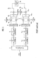
- FIG. 1 is a block diagram of a transmitting side of a MIMO system using the PARC method.
- a demultiplexer 2 demultiplexes a data stream prior to the data stream being transmitted via a plurality of transmitting antennas 16 1 to 16 M .
- the controller decide how many antennas will be selected among the M transmit antennas according to the channel quality information from receiver.
- the demultiplexing unit demultiplexes the input data stream into the substreams, the number of which is the number of selected antennas.
- the number of bits allocated to each of the antennas may be different based on a data rate of transmission via each antenna. That is, the MCS may be individually set for each antenna.
- the data stream After having been demultiplexed, the data stream forms sub-streams corresponding to the respective selected antenna in a 1:1 correspondence.
- M-1 antennas are selected.
- the sub-streams undergo coding and interleaving to be mapped to symbols, via the coding units 4 1 to 4 M-1 and the mapping units 6 1 to 6 M-1 , respectively.
- the symbols are then demultiplexed via the demultiplexer 8 prior to being spread by spreading codes in the spreading unit 10 1 to 10 M-1 , respectively.
- the demultiplexed spread signals are then combined in symbol combining units 12 1 to 12 M-1 , scrambled with the scrambling units 14 1 to 14 M-1 , and transmitted via the antennas 16 1 to 16 M .
- the coding is performed only in a time dimension and thus is not as powerful as space-time coding used in single-rate system.
- coding in the time domain cancels post-decoding interference, thereby enhancing the performance of a receiver.
- signals transmitted via the respective transmitting antennas can be independently decoded.
- a data stream input to the demultipexer 2 includes 9600 bits.
- the demultiplexer 2 then segments the input data stream into two data blocks including 4800 bits each, for example (assuming that two antennas are selected among three transmitting antennas).
- the two 4800 data bits are then processed by the coding, interleaving and mapping unit 4 1 to 4 M-1 and 6 1 to 6 M-1 .
- each of the 4800 bits is coded based on the coding scheme for that particular antenna (assume a turbo coding of 1 ⁇ 2 is used for the first substream and a turbo coding of 1/3 is used for the (M-1)-th substream to transmit via M-1 selected antennas among 16 1 ⁇ 16 M ).
- the first 4800 bits would be coded into 9600 bits (i.e., a turbo coding of 1 ⁇ 2) and the (M-1)-th 4800 bits would be coded into 14400 bits (i.e., a turbo coding of 1/3).
- the two coded blocks of data are then stored into an interleaver for mapping.
- Quadrature Amplitude Modulation QAM
- Quadrature Phase Shift Keying QPSK
- the first 9600 coded bits will be mapped into 2400 symbols (i.e., QAM maps 4 bits to one symbol and thus 9600 coded bits will be mapped into 2400 symbols).
- the (M-1)-th 14400 bits will be mapped into 7200 symbols (i.e., QPSK maps 2 bits into one symbol and thus 14400 coded bits will be mapped into 7200 symbols).
- the two separate coded and modulated data blocks are then demultiplexed by the demultiplexing units 8 1 to 8 M-1 and processed by the spreading unit 10 1 to 10 M-1 .
- the spreading unit 10 1 to 10 M-1 uses a variety of spreading codes such as OVSF (Orthogonal Variable Spreading Factor) codes to spread the data blocks so as to discriminate between different channels of each antenna.
- OVSF Orthogonal Variable Spreading Factor
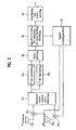
- the receiving side shown in Figure 2 of the MIMO system has the same spreading codes and despreads the received data using the same codes.
- the MIMO system is able to select a different MCS for each respective antenna to thereby increase the throughput of the system.
- the spread symbols are then combined in the symbol combining unit 12 1 to 12 M-1 scrambled in the scrambling unit 14 1 to 14 M-1 prior to being transmitted from the respective M-1 selected antennas among 16 1 ⁇ 16 M .
- the scrambling codes are used to discriminate cell regions (e.g., the received information is being received from Node B 1 rather than Node B 2, for example).
- the receiving operation reverses the transmitting operation to finally obtain the initially transmitted data.
- the receiving operation reverses the transmitting operation to finally obtain the initially transmitted data.
- the receiving side includes receiving antennas 20, interference removing unit 22, a Minimum Mean Square Error (MMSE) detector, despreaders 26, a multiplexer 28, a signal detection, de-mapping, de-interleaving and de-coding unit 30, a signal reconfiguration unit 32 and combining and multiplexing unit 34.
- MMSE Minimum Mean Square Error
- the MMSE detector 24 of the receiving end detects a signal having the greatest SINR (Signal-to-Interference Noise Ratio) among signals received through the plurality of reception antennas (20 1 ⁇ 20 N ) and performs an MMSE equalization on the signal Outputs of the MMSE detector 24 are despread in the despreaders 26 and then combined to one signal.
- the signal detection unit 30 detects a transmission symbol from a signal outputted from the multiplexer 28 and performs de-mapping and de-interleaving operations on the detected symbol to detect a first sub-stream.
- the signal reconfiguration unit 32 reconstructs the first sub-stream detected by the signal detecting unit 30 into a receiving signal form and outputs it to the interference removing unit 22.
- the interference removing unit 22 deletes a first detected signal component (reconstructed signal) from the receiving signal previously stored in the buffer and then the signal component-detected signal to the MMSE detector 24.
- the MMSE detector 24 equalizes the signal having the greatest SINR among the reconstructed signal-removed signals.
- An output of the MMSE detector 24 is inputted to the signal detection unit 30 through the despreaders 26 and the multiplexer 28, and the signal detection unit 30 detects a second sub-stream.
- the signal reconfiguration unit 32 reconstructs the second sub-stream which has been detected by the signal detection unit 30 and outputs it to the interference removing unit 22. Then, the interference removing unit 22 deletes the reconstructed signal from a signal previously stored in the buffer and outputs it to the MMSE detector 24.
- the signal detection unit 30 sequentially detects sub-streams. After all the sub-streams are detected by the signal detection unit 30, the combining unit 34 assembles the plurality of detected sub-streams to form one data stream.
- the V-BLAST system performs communications using M-transmitting antennas and N-receiving antennas.
- the sequentially generated data essentially passes through a serial-parallel converting circuit to be transmitted as separate signals in parallel via the respective antennas.
- the modulation and coding scheme (MCS) of the signal transmitted can be individually set for each antenna.
- individually selecting the MCS increases the throughput of the MIMO system.
- the receiving side must send signaling channel information to the transmitting side (such as Channel Quality Indicators (CQIs) indicating a quality of a channel).
- CQIs Channel Quality Indicators
- the MCS of four antennas are individually controlled, there is four times as much channel status information (such as CQIs) as compared to a single antenna using a single code.
- an extra signaling load is added to the MIMO system.
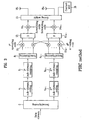
- FIG. 3 is a block diagram of a transmitting side of an MIMO system using the PSRC method.
- Note Figure 3 is similar to the transmitting side shown in Figure 1 , but includes a weight unit 15 for multiplying a data stream. Components in the previous figures which have been explained will not be repeated for brevity purposes.
- each stream is mapped to each antenna in one-to-one correspondence in the PARC method
- each stream is multiplied by an orthogonal weight vector having a size of a transmitting antenna number and the weighted streams are distributed to the transmitting antennas, respectively in the PSRC method. That is, for a transmitting end having four antennas the weight vector (eigen vector) will have four weight values.
- the same data stream is multiplied by the four different weight values and respectively transmitted by the four antennas.
- One stream of data is transmitted by the same method as Tx diversity which is an overlapping method for transmitting various streams with the same transmitting antenna combination.
- Figure 4 is a block diagram of a receiving side of a MIMO system using the PSRC method.
- the transmitting end in Figure 3 multiplied each stream by an orthogonal weight vector and transmitted the weighted data via a corresponding antenna
- the receiving side of the MIMO can receive each stream without interference by multiplying a Hermitian of the weight vector using a weight unit 23.
- the PSRC method on the receiving end does not need an interference countering process.
- the data streams are transmitted according to the number of the transmitting antennas. That is, each antenna is used to transmit data, which requires a control signal to be transmitted from the receiving end to the transmitting end for each data stream.
- the control signals include, for example, channel quality indicators (CQI) per stream for selection of a Modulation and Code Set (MCS), HARQ-ACK/NACK, etc.
- the transmission of a weight vector per stream is also required.
- Transmission control signals are also required to transmit control signals such as modulation information according to each stream, transport block size, HARQ processing information, etc to the receiving side from the transmitting side.
- control signals such as modulation information according to each stream, transport block size, HARQ processing information, etc.
- an increase in the number of streams also increases the number of control signals.
- the receiving side requires a number of receiving antennas that is greater then or equal to than the number of transport streams (i.e., M ⁇ N).
- a signal processing method in a receiving side of the MIMO is summarized as follows.
- the MIMO system includes M-transmitting antennas and N-receiving antennas.
- a signal vector transmitted via each of the M-transmitting antennas is represented by a and a channel matrix through which a transmission signal vector passes before being received in a receiving side is represented by H
- the channel matrix H can be defined as a N*M matrix.
- the signals (a 1 ,a 2 ,...,a M , i.e., M*1 vector) differently transmitted via the M-antennas pass through separate channels h i,j , respectively and are received in the receiving side via the N-antennas.
- ⁇ indicates Gaussian noise and is induced to the respective receiving antennas to become an (N+1) vector.
- the signals received via the N-antennas pass through a receiving side signal processing unit having the following signal search algorithm.
- a signal vector s resulting from detecting the transmission signal vector a , (a 1 ,a 2 ,...,a M ,) in the receiving side is expressed by (k 1 ,k 2 ,...,k M ).
- the N-antennas are multiplied by a weight vector that is denoted by w .
- the receiving side requires M-weight vectors to detect the signals.
- H j indicates the j th column vector of H.
- the weight vector w ⁇ i H which will be multiplied by the antenna of the receiving side to detect the i th transmission data, is '1' only for the multiplication by the j th column vector of H . Otherwise, the weight vector w ⁇ i H is '0' for the rest of the column vectors. That is, the weight vector w ⁇ i H for receiving the data transmitted from an i th transmitting antenna is calculated to remove the influence of the signals transmitted from the other transmitting antennas. Because the transmitted signals are sequentially detected, the influence of the previously detected signal is excluded before the weight vector to be used for current detection is found.
- the signals transmitted from the transmitting antennas pass through separate channels to be received in the receiving side, respectively, which is expressed by equation (3) in a linear sum total form.
- equation (3) in detecting a first transmission signal, it is preferable that reception is performed by multiplying a receiving antenna by the weight vector that allows the corresponding reception after the influence of a second to M th signals is removed.
- the weight vector can be updated in the following manner.
- a row vector having a smallest vector norm is searched from the respective row vectors of the matrix G 1 . If the row vector having the smallest value among vector norms of the row vectors is denoted by K , the weight vector w i for detecting a K th transmission signal is selected as a K th row of the matrix G 1 . In addition, a reception vector r 1 is then multiplied by the weight vector w i to detect the signal transmitted from a K th antenna. In this instance, as the transmitting side knows the modulation scheme (e.g., digital modulation such as QPSK, QAM, etc.), a signal a k finally transmitted from the K th transmission antenna is detected by deciding which constellation the signal belongs to.
- the modulation scheme e.g., digital modulation such as QPSK, QAM, etc.
- r 2 indicates a reception vector to be used in a second update.
- H k ⁇ + is the Moore-Penrose pseudo-inverse matrix of a matrix having K th column of the matrix H + set to '0'.
- a row vector having a smallest vector norm is searched from the respective row vectors of matrix G 2 . If the row vector having the smallest value among vector norms of the row vectors is denoted by V , the weight vector w v for detecting a V th transmission signal is selected as a V th row of the matrix G 2 . A reception vector r 2 is then multiplied by the weight vector w v to detect the signal transmitted from the V th antenna. Again, because the transmitting side knows the modulation scheme used (e.g., digital modulation such as QPSK, QAM, etc.), a signal â k finally transmitted from the V th transmission antenna can be detected by deciding which constellation the signal belongs to.
- the modulation scheme used e.g., digital modulation such as QPSK, QAM, etc.
- r 3 indicates a reception vector to be used in a third update. The above-explained procedures are repeated until all of the respective signals transmitted from the M-antennas are found.
- the PARC method transmits symbols from the respective antennas by reflecting channel statuses of the respective antennas differently on the channel coding and modulation of the symbols.
- the PARC method differs from the single rate MIMO V-BLAST technology in that the data rate (modulation and coding set) can be varied in each antenna.
- the PARC method allows independent control of a data rate of each antenna, whereby the throughput of the overall system is enhanced.
- a reference set can be decided. Namely, in the PARC method, to decide a Modulation and Coding Set (MCS) that is valid for each antenna, a received Signal to Interference Noise Ratio (SINR) from each transmitting antenna is calculated in the receiving antenna. That is, to select the proper MCS used in each antenna, the SINR received in each receiving antenna is measured. Then, the MSC to be used in each antenna is selected based on the measured SINR.
- MCS Modulation and Coding Set
- SINR Signal to Interference Noise Ratio
- Table 1 illustrates a data rate and MSC corresponding to the (4,4) system.
- Table 1 bps/Hz Data rate (Mbps) Modulation Code rate 3 7.2 16QAM 3/4 2 4.8 16QAM 1/2 1.5 3.6 QPSK 3/4 1 2.4 QPSK 1/2 0.5 1.2 QPSK 3/4
- a code reuse order is selected as '4' in highest geometries (index 1 to index 38) and another code reuse order of '2' is simultaneously used for selection in the index 39 to index 54. Further, for the lowest geometries, selective diversity and a single antenna transmission are used.
- Table 2 illustrates a data rate set in a system using a transmitting antenna and four receiving antennas (Table 2) Index Data rate: Mbps 1 st Ant. 2 nd Ant. 3 rd Ant. 4 th Ant. 1 28.8 3 3 3 3 2 26.4 3 3 2 3 3 26.4 3 2 3 3 4 6.4 2 3 3 3 5 24.0 2 3 3 2 6 24.0 2 3 2 3 7 24.0 2 2 3 3 8 21.6 2 2 3 2 9 21.6 2 2 2 3 10 19.2 2 2 2 2 11 22.8 2 1.5 3 3 12 20.4 2 1.5 2 3 13 18.0 2 1.5 2 2 14 19.2 2 1.5 1.5 2 15 16.8 2 1 2 2 16 25.2 1.5 3 3 3 17 22.8 1.5 3 2 3 18 22.8 1.5 2 3 3 19 20.4 1.5 2 2 3 20 18.0 1.5 2 2 2 21 19.2 1.5 2 1.5 2 22 21.6 1.5 1.5 3 3 23 21.6 1.5 1.5 3 3 24 16.8 1.5 1.5 2 2 25 14.4 1.5 1.5 2 1 26 15.6 1.5 1.5 1.5 2 27 15.6 1.5 1 2 2 28 24.0 1 3 3 29 21.6
- the transmitting side configures a signal vector s including M-symbols and transmits the symbols via separate transmitting antennas, respectively as shown in the below equation.
- s ⁇ s 1 ⁇ s 2 ... s M T
- the PSRC method transmits each symbol via an independent channel in an environment in which correlation between antennas and correlation between symbols exists. Namely, by paying attention to the antenna array configuration of the transmitting side, each symbol is multiplied by an eigenvector of channel matrix to be transmitted.
- higher-order modulation such as 64 Quadrature Amplitude Modulation (QAM), 16 QAM, etc. is used for an antenna having a relatively high eigen value after looking into a size of each eigenvalue through an eigenvalue decomposition of a channel matrix estimated by a receiving side in the MIMO communication system.
- low-order modulation such as BPSK (binary phase shift keying), QPSK (quadrature phase shift keying), etc. is used for an antenna having a relatively low eigenvalue.
- the same modulation is not used for the symbols transmitted from the respective transmitting antennas. Instead, a channel status is fed back from a terminal to the transmitting side to decide a modulation scheme to be used in each antenna based on the received channel status.
- the receiving side includes a same algorithm to recognize the modulation scheme as used in the respective transmitting antennas
- symbols are not transmitted at all to antennas of which eigenvalues resulted from the eigenvalue decomposition of the channel matrix are smaller than a specific value, thereby previously preventing the symbol transmitted from the transmitting antenna from bringing about errors to the receiving side.
- the symbol will be allocated to an antenna having a better channel status to use higher-order modulation, whereby the number of bits to be transmitted from the overall transmitting antennas will increase to enhance system throughput.
- the transmitting side previously handles an antenna of no use in symbol transmission so that the symbol is not transmitted from the handled antenna, whereby overall communication quality can be improved.
- the receiving side may feed back the respective eigenvectors separated from each other via eigenvalue decomposition to the transmitting side after having estimated the channel matrix, or the receiving side enables to keep a demodulation allocation table previously agreed between the transmitting and receiving sides via comparison of eigenvectors to feed back an index corresponding to the modulation scheme used in each antenna
- w i is a weight vector for forming a beam at each symbol
- s 1 to s M are data symbols, respectively
- S is a signal vector after forming the beam for each symbol.
- a channel status of each antenna is fed back to the transmitting side and then a modulation scheme to be used in each antenna is decided based on the channel status.
- s 1 to S M in equation 9 are selected to use different modulation schemes by comparing eigenvalues of a channel matrix, respectively. Namely, higher order modulation is allocated to an antenna having a relatively high eigenvalue through the eigenvalue decomposition of the channel matrix, whereas lower order modulation is allocated to an antenna having a relatively low eigenvalue.
- an MIMO system includes M-transmitting antennas and N-receiving antennas. If a mobile communication channel matrix that signal vectors differently transmitted via the M-transmitting antenna pass is H , the channel matrix H becomes a N*M matrix when the receiving side includes the N-receiving antennas. If a pilot symbol or a separate pilot channel, which is already recognized by the transmitting/receiving side, is transmitted from each of the transmitting antennas, the receiving side can estimate each component of the channel matrix H .
- the eigenvalue decomposition is performed on the channel matrix H by the receiving side.
- the channel matrix H can not become a square matrix, because the present invention assumes a system in which the number of antennas in the transmitting side is greater than that in the receiving side. Moreover, it is unable to execute eigenvalue decomposition directly on the channel matrix. Hence, the present invention executes the eigenvalue decomposition in a manner shown in the below equation.
- H H is a Hermitian operation for a vector H .
- ⁇ denotes eigenvalues of the matrix H H H and E indicates the eigenvectors. Further, the eigenvectors generally maintain orthogonality from each other. Hence, when intending to transmit symbols all together to fit the number of antennas in the transmitting side, each of the symbols are multiplied by an independent weight vector to transmit a corresponding symbol.
- the receiving side when the transmitting side forms a beam for each of the symbols and transmits a signal, the receiving side performs the following signal processing. Namely, the receiving side is unable to utilize the signal processing of the previously discussed V-BLAST receiving side, because the signal is transmitted by multiplying each of the symbols by the independent weight vector. Hence, each of the symbols is detected by preferentially estimating S by Zero-Forcing or Minimum Mean Square Error (MMSE) techniques and then by multiplying S by a conjugate of the weight vector having been multiplied by each of the symbols in the transmitting side.
- MMSE Minimum Mean Square Error
- n is an additive white Gaussian noise (AWGN).
- a signal Vector s by multiplying each symbol by a weight vector using MMSE can be represented by the below equation (13).
- s ⁇ ⁇ ⁇ ⁇ I ⁇ + H ⁇ H ⁇ H ⁇ - 1 ⁇ H ⁇ H ⁇ R ⁇
- Equation 13 ⁇ is a signal to interference noise ratio and I is an identity matrix.
- the estimated signal Vector ⁇ is multiplied again by a conjugate of the weight vector transmitted by being multiplied by each symbol in the transmitting side so that estimated values ⁇ I to ⁇ M of the symbols S 1 to S M transmitted from the transmitting side can be estimated according to the following equation 14.
- the estimated ⁇ I to ⁇ M are demodulated to fit the used modulation so that the bits prior to being allocated to the respective symbols are found.
- the bit stream transmitted from the transmitting side is determined via multiplexing.
- the symbols are multiplied by eigenvectors of the channel matrix estimated by the transmitting side to transmit, respectively.
- the channel coding and modulation schemes of the symbols to be transmitted from the respective antennas are selected in the receiving side.
- the modulation scheme that will be used in each antenna is decided to fit the channel status of each antenna not by using the same modulation for the symbols transmitted from the respective transmitting antennas but by receiving channels statuses of the respective antennas through feedback.
- the symbols s 1 to s M in Equation (2) are made to use separate modulation schemes via the comparison of eigenvalues of the channel matrix, respectively. Namely, through the eigenvalue decomposition of the channel matrix, higher order modulation is allocated to an antenna having a relatively high eigenvalue and lower order modulation is allocated to an antenna having a relatively low eigenvalue.
- a relative ratio of each eigenvalue is preferentially decided to determine a modulation scheme to be allocated to each antenna with the eigenvalues determined through eigenvalue decomposition such as shown in equation (10).
- the symbols are made not to be transmitted from the corresponding antenna.
- the lowest modulation and coding set is used for the minimum eigenvalue except the excluded eigenvalue.
- the higher order modulation and coding set is used for an antenna having the highest eigenvalue.
- the modulation and coding set of a middle step is used through the comparison of the relative values. Instead, by preparing such a necessary reference as Table 2 previously after confirming various channel statuses through a simulation test, it may be able to select to utilize the corresponding modulation and coding set to fit the channel status with the prepared reference.
- the available modulation and coding are limited to their kind, a set of the available modulation and coding is prepared such as in Table 1.
- the MCS to be used in each antenna can be informed via an index because both of the transmitting and receiving sides already know the same reference. Instead, considering that the eigenvalues of the channel matrix vary relatively slow, the entire eigenvalues can return slowly. In such a case, with the returning eigenvalue, the modulation and coding to be used in each antenna should be decided in the transmitting side.
- An MIMO system including M-transmitting antennas and N-receiving antennas uses a method based on transmission of M-streams. If the number of transmitting antennas is 'M', the number of transmittable channels is 'M'. Yet, it does not frequently happen that the overall channels are in good situation each moment. Hence, the present invention is based on the P-streams (P ⁇ M) transmission.
- the data streams of which number is less than 'P' are transmitted using P-channels only.
- Signals needed to control the corresponding transmission are independent P-control signals and index information of channels selected from the M-channels.
- the method according to the present invention only uses P-control signals and indexes of the channels selected from the M-channels, whereas the other methods require independent M-control signals.
- w p is a P th one in an eigenvalue size order corresponding to an eigenvector of channel matrix. Namely, eigenvectors having the corresponding eigenvalues after the Pth one in the size order are excluded.
- the present invention restricts the transmission stream number to be equal to or smaller than the valid stream number, thereby advantageously reducing the complicated control signals.
- the present invention prevents the channel having a low eigen value from being used, thereby considerably reducing throughput loss.
- the system reduces a transmission amount of weight vectors transmitted to the transmitting side, thereby decreasing a feedback delay or a quantization error.
- the number of transport streams is lowered to T' from 'M', whereby the number of receiving antennas of a terminal receiving the transport streams can be reduced to 'P'. Assuming that the number of transmitting/receiving antennas is (4,4), an amount of control signals is reduced to half as well as the number of receiving antennas is reduced to '2' if a pair of streams are only transmitted only.
- the method for controlling signal transmission in a MIMO system includes selecting a MCS (for the PSRC method) and weight (eigen) vectors (for the PSRC method) for data stream(s) to be transmitted by M transmitting antennas (step S10).
- the initial data is then transmitted using the selected MCS/weight vectors (step S20), and channel quality information (e.g., SINR) is received from the receiving end (step S30).
- channel quality information e.g., SINR
- the received SINR information may be compared with a threshold (or be compared against each other) in step S40, and a selective M-1 or fewer transmission on antennas/weight vectors are selected (step S50) via the control unit 18 in Figures 1 and 3 .
- data is then transmitted using the selected antennas/weight vectors (step S60).
- the amount of control signaling etc. is advantageously reduced.
- This invention may be conveniently implemented using a conventional general purpose digital computer or microprocessor programmed according to the teachings of the present specification, as well be apparent to those skilled in the computer art.
- Appropriate software coding can readily be prepared by skilled programmers based on the teachings of the present disclosure, as will be apparent to those skilled in the software are.
- the invention may also be implemented by the preparation of application specific integrated circuits or by interconnecting an appropriate network of conventional component circuits, as will be readily apparent to those skilled in the art.
- the present invention includes a computer program product which is a storage medium including instructions which can be used to program a computer to perform a process of the invention.
- the storage medium can include, but is not limited to, any type of disk including floppy disks, optical discs, CD-ROMs, and magneto-optical disks, ROMs, RAMs, EPROMs, EEPROMs, magnetic or optical cards, or any type of media suitable for storing electronic instructions.
- the present invention can be applicable to wireless communication systems.
Landscapes
- Engineering & Computer Science (AREA)
- Computer Networks & Wireless Communication (AREA)
- Signal Processing (AREA)
- Quality & Reliability (AREA)
- Radio Transmission System (AREA)
- Mobile Radio Communication Systems (AREA)
- Selective Calling Equipment (AREA)
Claims (7)
- Procédé de commande de transmission de signal dans un système de communication à plusieurs entrées et plusieurs sorties, MIMO, comprenant :- la transmission (S20) d'un nombre M de flux par l'intermédiaire de M antennes de transmission (16) à une extrémité de transmission du système MIMO ; caractérisé par- la sélection (S50) de P antennes de transmission parmi les M antennes de transmission (16) sur la base d'informations de statut de canal reçues à une extrémité de réception du système MIMO et indiquant une performance de transmission des M antennes de transmission (16) ;- la transmission (S60) d'un nombre P de flux de données par l'intermédiaire des P antennes de transmission, dans lequel chacun du nombre P de flux de données est traité avec l'un correspondant d'ensembles de modulation et de code qui sont sélectionnés individuellement pour les P antennes de transmission, dans lequel P est un nombre naturel inférieur à M ;- la réception, à l'extrémité de réception, d'informations de rétroaction uniquement pour les P antennes de transmission.
- Procédé selon la revendication 1, dans lequel les informations de statut de canal comprennent un rapport de signal sur bruit d'interférence (SINR).
- Procédé selon la revendication 1, dans lequel la sélection (S50) de P antennes de transmission comprend :- la comparaison (S40) des informations de statut de canal pour chacune des M antennes de transmission à un seuil prédéterminé ; et- la sélection sélective des P antennes de transmission (S50) ayant des informations de qualité de canal supérieures ou égales au seuil prédéterminé.
- Procédé selon la revendication 1, dans lequel les ensembles de modulation et de code sont sélectionnés selon une méthode de transmission à régulation de débit par antenne (PARC).
- Système de communication à plusieurs entrées et plusieurs sorties, MIMO, comprenant :une unité de régulation de débit par antenne (PARC) configurée pour transmettre un nombre M de flux par l'intermédiaire de M antennes de transmission (16) à une extrémité de transmission du système MIMO ;caractérisé en ce quel'unité PARC comprend une unité de commande (18) qui est configurée pour sélectionner P antennes de transmission parmi les M antennes de transmission (16) sur la base d'informations de statut de canal reçues à une extrémité de réception du système MIMO et indiquant une performance de transmission des M antennes de transmission (16), pour transmettre un nombre P de flux de données par l'intermédiaire de P antennes de transmission, et pour recevoir des informations de rétroaction uniquement pour les P antennes de transmission à l'extrémité de réception,dans lequel P est un nombre naturel inférieur à M, et chacun du nombre P de flux de données est traité avec l'un correspondant des ensembles de modulation et de code qui sont sélectionnés individuellement pour les P antennes de transmission.
- Système selon la revendication 5, comprenant en outre
une extrémité de réception configurée pour transmettre les informations de statut de canal à l'extrémité de transmission du système MIMO, dans lequel les informations de statut de canal comprennent un rapport de signal sur bruit d'interférence (SINR). - Système selon la revendication 5, dans lequel l'unité de commande (18) compare les informations de statut de canal pour chacune des M antennes de transmission (16) à un seuil prédéterminé, et sélectionne sélectivement les P antennes de transmission ayant des informations de statut de canal supérieures ou égales au seuil prédéterminé.
Applications Claiming Priority (2)
| Application Number | Priority Date | Filing Date | Title |
|---|---|---|---|
| KR1020030068307A KR100995031B1 (ko) | 2003-10-01 | 2003-10-01 | 다중입력 다중출력 시스템에 적용되는 신호 전송 제어 방법 |
| EP04774710A EP1668855B1 (fr) | 2003-10-01 | 2004-09-24 | Procede de regulation de la transmission de signaux dans un systeme a entrees/sorties multiples |
Related Parent Applications (2)
| Application Number | Title | Priority Date | Filing Date |
|---|---|---|---|
| EP04774710.0 Division | 2004-09-24 | ||
| EP04774710A Division EP1668855B1 (fr) | 2003-10-01 | 2004-09-24 | Procede de regulation de la transmission de signaux dans un systeme a entrees/sorties multiples |
Publications (2)
| Publication Number | Publication Date |
|---|---|
| EP1933492A1 EP1933492A1 (fr) | 2008-06-18 |
| EP1933492B1 true EP1933492B1 (fr) | 2011-11-02 |
Family
ID=36284328
Family Applications (2)
| Application Number | Title | Priority Date | Filing Date |
|---|---|---|---|
| EP08002667A Expired - Lifetime EP1933492B1 (fr) | 2003-10-01 | 2004-09-24 | Procédé de contrôle de transmission de signal dans un système d'entrées/sorties multiples |
| EP04774710A Expired - Lifetime EP1668855B1 (fr) | 2003-10-01 | 2004-09-24 | Procede de regulation de la transmission de signaux dans un systeme a entrees/sorties multiples |
Family Applications After (1)
| Application Number | Title | Priority Date | Filing Date |
|---|---|---|---|
| EP04774710A Expired - Lifetime EP1668855B1 (fr) | 2003-10-01 | 2004-09-24 | Procede de regulation de la transmission de signaux dans un systeme a entrees/sorties multiples |
Country Status (7)
| Country | Link |
|---|---|
| US (2) | US7929633B2 (fr) |
| EP (2) | EP1933492B1 (fr) |
| KR (1) | KR100995031B1 (fr) |
| CN (1) | CN1864379A (fr) |
| AT (2) | ATE532285T1 (fr) |
| DE (1) | DE602004016189D1 (fr) |
| WO (1) | WO2005032154A2 (fr) |
Families Citing this family (62)
| Publication number | Priority date | Publication date | Assignee | Title |
|---|---|---|---|---|
| US7170926B2 (en) * | 2001-11-29 | 2007-01-30 | Interdigital Technology Corporation | Efficient multiple input multiple output system for multi-path fading channels |
| US9270410B2 (en) | 2002-04-22 | 2016-02-23 | Texas Instruments Incorporated | MIMO PGRC system and method |
| US8194770B2 (en) | 2002-08-27 | 2012-06-05 | Qualcomm Incorporated | Coded MIMO systems with selective channel inversion applied per eigenmode |
| US7002900B2 (en) | 2002-10-25 | 2006-02-21 | Qualcomm Incorporated | Transmit diversity processing for a multi-antenna communication system |
| US8208364B2 (en) | 2002-10-25 | 2012-06-26 | Qualcomm Incorporated | MIMO system with multiple spatial multiplexing modes |
| US8570988B2 (en) | 2002-10-25 | 2013-10-29 | Qualcomm Incorporated | Channel calibration for a time division duplexed communication system |
| US7324429B2 (en) | 2002-10-25 | 2008-01-29 | Qualcomm, Incorporated | Multi-mode terminal in a wireless MIMO system |
| US20040081131A1 (en) | 2002-10-25 | 2004-04-29 | Walton Jay Rod | OFDM communication system with multiple OFDM symbol sizes |
| US8320301B2 (en) | 2002-10-25 | 2012-11-27 | Qualcomm Incorporated | MIMO WLAN system |
| US8218609B2 (en) | 2002-10-25 | 2012-07-10 | Qualcomm Incorporated | Closed-loop rate control for a multi-channel communication system |
| US8170513B2 (en) | 2002-10-25 | 2012-05-01 | Qualcomm Incorporated | Data detection and demodulation for wireless communication systems |
| US8134976B2 (en) | 2002-10-25 | 2012-03-13 | Qualcomm Incorporated | Channel calibration for a time division duplexed communication system |
| US8169944B2 (en) | 2002-10-25 | 2012-05-01 | Qualcomm Incorporated | Random access for wireless multiple-access communication systems |
| US7986742B2 (en) | 2002-10-25 | 2011-07-26 | Qualcomm Incorporated | Pilots for MIMO communication system |
| JP4287670B2 (ja) * | 2003-02-18 | 2009-07-01 | パナソニック株式会社 | 通信装置及び通信方法 |
| US9473269B2 (en) | 2003-12-01 | 2016-10-18 | Qualcomm Incorporated | Method and apparatus for providing an efficient control channel structure in a wireless communication system |
| US8249518B2 (en) | 2003-12-29 | 2012-08-21 | Telefonaktiebolaget Lm Ericsson (Publ) | Network controlled feedback for MIMO systems |
| EP1849123A2 (fr) | 2005-01-07 | 2007-10-31 | GestureTek, Inc. | Capteur d'inclinaison base sur un flux optique |
| US7729325B2 (en) * | 2005-04-05 | 2010-06-01 | Toshiba America Research, Inc. | Beamforming and distributed opportunistic scheduling in wireless networks |
| US7986680B2 (en) * | 2005-04-28 | 2011-07-26 | Qualcomm Incorporated | Transmit format selection with consideration for resource reuse |
| EP2106084B1 (fr) * | 2005-05-04 | 2012-02-15 | Panasonic Corporation | Transmissions de données dans un système de communication mobile utilisant le réagencement de diversité et de constellation d'un schéma 16 QAM |
| US7466749B2 (en) | 2005-05-12 | 2008-12-16 | Qualcomm Incorporated | Rate selection with margin sharing |
| US9130706B2 (en) * | 2005-05-26 | 2015-09-08 | Unwired Planet, Llc | Method and apparatus for signal quality loss compensation in multiplexing transmission systems |
| US8358714B2 (en) * | 2005-06-16 | 2013-01-22 | Qualcomm Incorporated | Coding and modulation for multiple data streams in a communication system |
| DE102005043001B4 (de) * | 2005-09-09 | 2014-06-05 | Intel Mobile Communications GmbH | Verfahren zum Senden mehrerer Datenströme, Verfahren zum Demultiplexen von mittels mehrerer Empfangsantennen empfangenen Sende-Datenströmen, Sendeeinrichtung zum Senden mehrerer Datenströme, Empfangseinrichtung zum Demultiplexen von mittels mehrerer Empfangsantennen empfangenen Sende-Datenströmen und Computerprogrammelemente |
| US8054898B2 (en) * | 2005-10-12 | 2011-11-08 | Nortel Networks Limited | Multi-user MIMO systems and methods |
| US8335272B2 (en) | 2005-10-28 | 2012-12-18 | Koninklijke Philips Electronics N.V. | Multiple antenna transmission with variable diversity gain |
| PL1961143T3 (pl) | 2005-12-09 | 2016-09-30 | Transmisja na wielu kanałach przestrzennych ze sterowaniem szybkością | |
| GB2433397B (en) * | 2005-12-16 | 2008-09-10 | Toshiba Res Europ Ltd | A configurable block cdma scheme |
| US20080051037A1 (en) | 2005-12-29 | 2008-02-28 | Molnar Karl J | BASE STATION AND METHOD FOR SELECTING BEST TRANSMIT ANTENNA(s) FOR SIGNALING CONTROL CHANNEL INFORMATION |
| US20070165576A1 (en) * | 2005-12-29 | 2007-07-19 | Telefonaktiebolaget Lm Ericsson (Publ) | Mimo control channel with shared channelization codes |
| EP1981197A4 (fr) * | 2006-01-31 | 2011-03-23 | Mitsubishi Electric Corp | Dispositif de transmission radio, dispositif de reception radio et systeme de communication radio |
| RU2391795C2 (ru) * | 2006-02-03 | 2010-06-10 | Интердиджитал Текнолоджи Корпорейшн | Устройство и процедура определения и распределения ресурсов на основе качества обслуживания в системах развития и долгосрочного развития высокоскоростного пакетного доступа |
| KR100950654B1 (ko) * | 2006-03-03 | 2010-04-01 | 삼성전자주식회사 | 다중 입력 다중 출력 방식을 사용하는 통신 시스템에서신호 송수신 장치 및 방법 |
| CN101043241A (zh) * | 2006-03-20 | 2007-09-26 | 华为技术有限公司 | 多天线通信方法和系统 |
| US8134932B2 (en) | 2006-03-24 | 2012-03-13 | Telefonaktiebolaget Lm Ericsson (Publ) | Method and arrangement in a telecommunication system |
| AU2007240912B2 (en) * | 2006-04-18 | 2010-05-20 | Interdigital Technology Corporation | Method and apparatus for implementing H-ARQ in a mimo wireless communication system |
| US7751368B2 (en) * | 2006-05-01 | 2010-07-06 | Intel Corporation | Providing CQI feedback to a transmitter station in a closed-loop MIMO system |
| BRPI0712598B1 (pt) | 2006-05-19 | 2019-10-29 | Panasonic Corp | dispositivo de transmissão de rádio e método de transmissão de rádio |
| EP2044700B1 (fr) * | 2006-07-12 | 2015-10-21 | Intel Corporation | Systèmes et procédés de détermination d'un schéma de modulation et de codage prévisible |
| HUE044531T2 (hu) * | 2006-08-28 | 2019-10-28 | Koninklijke Philips Nv | Hatékony CQI jelzés változó számú sugárral rendelkezõ MIMO rendszerekben |
| JP5235342B2 (ja) * | 2007-06-22 | 2013-07-10 | キヤノン株式会社 | 通信装置、制御方法及びプログラム |
| CN101335910B (zh) * | 2007-06-29 | 2012-02-29 | 中国移动通信集团公司 | 智能天线与多输入多输出天线的复用天线系统和方法 |
| CN101340609B (zh) * | 2007-07-04 | 2011-10-26 | 上海华为技术有限公司 | 广播多播业务发送方法、设备及系统 |
| CN101102141B (zh) * | 2007-08-03 | 2012-11-28 | 中兴通讯股份有限公司 | 多输入多输出数据流数目选择方法及系统 |
| EP2615114B1 (fr) | 2007-08-23 | 2022-04-06 | Amgen Inc. | Protéines de liaison à un antigène pour proprotéine convertase subtilisine kexine de type 9 (PCSK9) |
| US7778340B2 (en) * | 2007-09-06 | 2010-08-17 | Hong Kong Applied Science And Technology Research Institute Co., Ltd. | Accurate channel quality indicator for link adaptation of MIMO communication systems |
| JP2009098658A (ja) * | 2007-09-25 | 2009-05-07 | Fujifilm Corp | 光学フィルム、偏光板、及び画像表示装置 |
| JP5069579B2 (ja) * | 2008-01-30 | 2012-11-07 | 京セラ株式会社 | 無線通信システム、無線通信装置および無線通信方法 |
| US8144797B2 (en) | 2008-03-25 | 2012-03-27 | Intel Mobile Communications GmbH | CQI table for wireless MIMO networks |
| EP2522085A2 (fr) * | 2010-01-07 | 2012-11-14 | InterDigital Patent Holdings, Inc. | Procédé et appareil permettant d'effectuer une diversité d'émission d'antenne sur la liaison montante |
| CN102208928B (zh) * | 2010-03-29 | 2014-12-10 | 中兴通讯股份有限公司 | 多天线信道极化功率损失的建模方法及装置 |
| CN102611541B (zh) * | 2011-12-26 | 2017-05-03 | 中兴通讯股份有限公司 | 天线增益不平衡的数据重传方法及装置 |
| EP2645653B1 (fr) * | 2012-03-30 | 2016-03-30 | NTT DoCoMo, Inc. | Calculateur de filtre de transmission, dispositif de communication et procédés |
| CN103516486B (zh) * | 2012-06-19 | 2018-08-07 | 中兴通讯股份有限公司 | 基于矢量选择调制的多天线传输方法、接收方法和装置 |
| US9197302B2 (en) * | 2013-11-21 | 2015-11-24 | Sony Corporation | MIMO communication method |
| EP3084978B1 (fr) * | 2013-12-20 | 2019-11-13 | Telefonaktiebolaget LM Ericsson (publ) | Procédé, système de communication et programme informatique de sélection de secteurs |
| CN104219528B (zh) * | 2014-09-09 | 2017-08-15 | 南京大学 | 一种支持可分级视频编码的mimo系统的视频传输方法 |
| TWI744242B (zh) | 2015-07-31 | 2021-11-01 | 德商安美基研究(慕尼黑)公司 | Egfrviii及cd3抗體構築體 |
| US11539908B2 (en) * | 2017-09-29 | 2022-12-27 | Advanced Micro Devices, Inc. | Adjustable modulation coding scheme to increase video stream robustness |
| US10476628B2 (en) * | 2017-11-27 | 2019-11-12 | Comtech Systems Inc. | Adaptive coding and modulation (ACM) transceiver system |
| US11558820B2 (en) * | 2019-11-05 | 2023-01-17 | Qualcomm Incorporated | Power saving in new radio multicast |
Family Cites Families (12)
| Publication number | Priority date | Publication date | Assignee | Title |
|---|---|---|---|---|
| US6959048B1 (en) | 1999-10-19 | 2005-10-25 | Nokia Networks Oy | Optimizing link quality by space and time interleaving |
| US6985434B2 (en) * | 2000-09-01 | 2006-01-10 | Nortel Networks Limited | Adaptive time diversity and spatial diversity for OFDM |
| JP3923263B2 (ja) | 2001-01-30 | 2007-05-30 | 日本電波工業株式会社 | 複合型水晶振動子及びこれを用いたオーバトーン水晶発振器 |
| US6859503B2 (en) * | 2001-04-07 | 2005-02-22 | Motorola, Inc. | Method and system in a transceiver for controlling a multiple-input, multiple-output communications channel |
| US6662024B2 (en) * | 2001-05-16 | 2003-12-09 | Qualcomm Incorporated | Method and apparatus for allocating downlink resources in a multiple-input multiple-output (MIMO) communication system |
| US7072413B2 (en) | 2001-05-17 | 2006-07-04 | Qualcomm, Incorporated | Method and apparatus for processing data for transmission in a multi-channel communication system using selective channel inversion |
| US7126996B2 (en) * | 2001-12-28 | 2006-10-24 | Motorola, Inc. | Adaptive transmission method |
| KR100421371B1 (ko) * | 2002-02-19 | 2004-03-06 | 엘지전자 주식회사 | 이동통신 시스템의 적응형 변조 및 코딩 방법 |
| US7184713B2 (en) * | 2002-06-20 | 2007-02-27 | Qualcomm, Incorporated | Rate control for multi-channel communication systems |
| US8179864B2 (en) * | 2002-08-06 | 2012-05-15 | Rockstar Bidco Lp | Method of controlling a communications link |
| US6917821B2 (en) * | 2003-09-23 | 2005-07-12 | Qualcomm, Incorporated | Successive interference cancellation receiver processing with selection diversity |
| US20050250544A1 (en) * | 2004-05-07 | 2005-11-10 | Stephen Grant | Base station, mobile terminal device and method for implementing a selective-per-antenna-rate-control (S-PARC) technique in a wireless communications network |
-
2003
- 2003-10-01 KR KR1020030068307A patent/KR100995031B1/ko active IP Right Grant
-
2004
- 2004-09-22 US US10/946,342 patent/US7929633B2/en active Active
- 2004-09-24 WO PCT/KR2004/002460 patent/WO2005032154A2/fr active Application Filing
- 2004-09-24 EP EP08002667A patent/EP1933492B1/fr not_active Expired - Lifetime
- 2004-09-24 EP EP04774710A patent/EP1668855B1/fr not_active Expired - Lifetime
- 2004-09-24 DE DE602004016189T patent/DE602004016189D1/de not_active Expired - Lifetime
- 2004-09-24 AT AT08002667T patent/ATE532285T1/de active
- 2004-09-24 AT AT04774710T patent/ATE406743T1/de not_active IP Right Cessation
- 2004-09-24 CN CNA2004800286357A patent/CN1864379A/zh active Pending
-
2008
- 2008-05-27 US US12/127,212 patent/US8031801B2/en active Active
Also Published As
| Publication number | Publication date |
|---|---|
| CN1864379A (zh) | 2006-11-15 |
| US20080260060A1 (en) | 2008-10-23 |
| US20050147177A1 (en) | 2005-07-07 |
| EP1668855B1 (fr) | 2008-08-27 |
| US7929633B2 (en) | 2011-04-19 |
| ATE532285T1 (de) | 2011-11-15 |
| KR100995031B1 (ko) | 2010-11-19 |
| WO2005032154A2 (fr) | 2005-04-07 |
| WO2005032154A3 (fr) | 2005-06-16 |
| DE602004016189D1 (de) | 2008-10-09 |
| US8031801B2 (en) | 2011-10-04 |
| KR20050032278A (ko) | 2005-04-07 |
| EP1668855A2 (fr) | 2006-06-14 |
| ATE406743T1 (de) | 2008-09-15 |
| EP1933492A1 (fr) | 2008-06-18 |
Similar Documents
| Publication | Publication Date | Title |
|---|---|---|
| EP1933492B1 (fr) | Procédé de contrôle de transmission de signal dans un système d'entrées/sorties multiples | |
| US7120199B2 (en) | Link adaptation for MIMO transmission schemes | |
| US7551589B2 (en) | Frame structure of uplink control information transmission channel in MIMO communication system | |
| US7697625B2 (en) | Method and system for transmitting and receiving data streams | |
| US8059771B2 (en) | Method and system for transmitting and receiving data streams | |
| KR100955795B1 (ko) | 다중-송신 다중-수신 안테나 어레이들을 이용한 무선 통신 | |
| EP1575188B1 (fr) | Procédé et appareil pour la transmission et/ou la réception d'un signal dans un système de communication MIMO | |
| EP1668792B1 (fr) | Methode de commande de modulation de donnees et de codage appliquee a un systeme multi-sortie/multi-entree | |
| US20090175320A1 (en) | Method to Determine the Number of Data Streams to Be Used in a MIMO System | |
| US20050220211A1 (en) | Signal processing apparatus and method in multi-input/multi-output communications systems | |
| US20080170523A1 (en) | Method and apparatus for feedback information transmitting/receiving in mobile telecommunication using multiple input multiple output | |
| WO2005099125A1 (fr) | Structure de trame d'une voie de transmission d'informations de commande de liaison montante pour systeme mimo | |
| WO2005050886A2 (fr) | Procede de division a debit modulable pour transmission mimo | |
| KR101319878B1 (ko) | Mimo 통신 시스템에서 코드워드와 스트림의 조합 표시방법 | |
| EP1658686B1 (fr) | Dispositif et procede de traitement de signal pour systeme de communication multi-entree/multi-sortie | |
| KR100913101B1 (ko) | 다중입력 다중출력 시스템에 적용되는 신호전송방법 | |
| KR100550720B1 (ko) | 다중 입출력 통신 시스템의 신호처리 장치 및 방법 | |
| KR20040063324A (ko) | 다중 입출력 통신 시스템에서의 상향 제어정보 전송채널의 프레임 구조 | |
| Xiao et al. | Canceling co-channel interference for MIMO CDMA systems | |
| Getu et al. | MIMO systems in random uncorrelated, correlated and deterministic radio channels | |
| Zacarıas | BLAST Architectures |
Legal Events
| Date | Code | Title | Description |
|---|---|---|---|
| PUAI | Public reference made under article 153(3) epc to a published international application that has entered the european phase |
Free format text: ORIGINAL CODE: 0009012 |
|
| 17P | Request for examination filed |
Effective date: 20080213 |
|
| AC | Divisional application: reference to earlier application |
Ref document number: 1668855 Country of ref document: EP Kind code of ref document: P |
|
| AK | Designated contracting states |
Kind code of ref document: A1 Designated state(s): AT BE BG CH CY CZ DE DK EE ES FI FR GB GR HU IE IT LI LU MC NL PL PT RO SE SI SK TR |
|
| 17Q | First examination report despatched |
Effective date: 20090123 |
|
| AKX | Designation fees paid |
Designated state(s): AT BE BG CH CY CZ DE DK EE ES FI FR GB GR HU IE IT LI LU MC NL PL PT RO SE SI SK TR |
|
| GRAP | Despatch of communication of intention to grant a patent |
Free format text: ORIGINAL CODE: EPIDOSNIGR1 |
|
| RAP1 | Party data changed (applicant data changed or rights of an application transferred) |
Owner name: LG ELECTRONICS INC. |
|
| GRAS | Grant fee paid |
Free format text: ORIGINAL CODE: EPIDOSNIGR3 |
|
| GRAA | (expected) grant |
Free format text: ORIGINAL CODE: 0009210 |
|
| AC | Divisional application: reference to earlier application |
Ref document number: 1668855 Country of ref document: EP Kind code of ref document: P |
|
| AK | Designated contracting states |
Kind code of ref document: B1 Designated state(s): AT BE BG CH CY CZ DE DK EE ES FI FR GB GR HU IE IT LI LU MC NL PL PT RO SE SI SK TR |
|
| REG | Reference to a national code |
Ref country code: GB Ref legal event code: FG4D |
|
| REG | Reference to a national code |
Ref country code: CH Ref legal event code: EP |
|
| REG | Reference to a national code |
Ref country code: IE Ref legal event code: FG4D |
|
| REG | Reference to a national code |
Ref country code: DE Ref legal event code: R096 Ref document number: 602004035180 Country of ref document: DE Effective date: 20120112 |
|
| REG | Reference to a national code |
Ref country code: NL Ref legal event code: VDEP Effective date: 20111102 |
|
| PG25 | Lapsed in a contracting state [announced via postgrant information from national office to epo] |
Ref country code: PT Free format text: LAPSE BECAUSE OF FAILURE TO SUBMIT A TRANSLATION OF THE DESCRIPTION OR TO PAY THE FEE WITHIN THE PRESCRIBED TIME-LIMIT Effective date: 20120302 Ref country code: SI Free format text: LAPSE BECAUSE OF FAILURE TO SUBMIT A TRANSLATION OF THE DESCRIPTION OR TO PAY THE FEE WITHIN THE PRESCRIBED TIME-LIMIT Effective date: 20111102 Ref country code: BE Free format text: LAPSE BECAUSE OF FAILURE TO SUBMIT A TRANSLATION OF THE DESCRIPTION OR TO PAY THE FEE WITHIN THE PRESCRIBED TIME-LIMIT Effective date: 20111102 Ref country code: SE Free format text: LAPSE BECAUSE OF FAILURE TO SUBMIT A TRANSLATION OF THE DESCRIPTION OR TO PAY THE FEE WITHIN THE PRESCRIBED TIME-LIMIT Effective date: 20111102 Ref country code: PL Free format text: LAPSE BECAUSE OF FAILURE TO SUBMIT A TRANSLATION OF THE DESCRIPTION OR TO PAY THE FEE WITHIN THE PRESCRIBED TIME-LIMIT Effective date: 20111102 Ref country code: GR Free format text: LAPSE BECAUSE OF FAILURE TO SUBMIT A TRANSLATION OF THE DESCRIPTION OR TO PAY THE FEE WITHIN THE PRESCRIBED TIME-LIMIT Effective date: 20120203 Ref country code: NL Free format text: LAPSE BECAUSE OF FAILURE TO SUBMIT A TRANSLATION OF THE DESCRIPTION OR TO PAY THE FEE WITHIN THE PRESCRIBED TIME-LIMIT Effective date: 20111102 |
|
| PG25 | Lapsed in a contracting state [announced via postgrant information from national office to epo] |
Ref country code: CY Free format text: LAPSE BECAUSE OF FAILURE TO SUBMIT A TRANSLATION OF THE DESCRIPTION OR TO PAY THE FEE WITHIN THE PRESCRIBED TIME-LIMIT Effective date: 20111102 |
|
| PG25 | Lapsed in a contracting state [announced via postgrant information from national office to epo] |
Ref country code: DK Free format text: LAPSE BECAUSE OF FAILURE TO SUBMIT A TRANSLATION OF THE DESCRIPTION OR TO PAY THE FEE WITHIN THE PRESCRIBED TIME-LIMIT Effective date: 20111102 Ref country code: SK Free format text: LAPSE BECAUSE OF FAILURE TO SUBMIT A TRANSLATION OF THE DESCRIPTION OR TO PAY THE FEE WITHIN THE PRESCRIBED TIME-LIMIT Effective date: 20111102 Ref country code: CZ Free format text: LAPSE BECAUSE OF FAILURE TO SUBMIT A TRANSLATION OF THE DESCRIPTION OR TO PAY THE FEE WITHIN THE PRESCRIBED TIME-LIMIT Effective date: 20111102 Ref country code: BG Free format text: LAPSE BECAUSE OF FAILURE TO SUBMIT A TRANSLATION OF THE DESCRIPTION OR TO PAY THE FEE WITHIN THE PRESCRIBED TIME-LIMIT Effective date: 20120202 Ref country code: EE Free format text: LAPSE BECAUSE OF FAILURE TO SUBMIT A TRANSLATION OF THE DESCRIPTION OR TO PAY THE FEE WITHIN THE PRESCRIBED TIME-LIMIT Effective date: 20111102 |
|
| PG25 | Lapsed in a contracting state [announced via postgrant information from national office to epo] |
Ref country code: IT Free format text: LAPSE BECAUSE OF FAILURE TO SUBMIT A TRANSLATION OF THE DESCRIPTION OR TO PAY THE FEE WITHIN THE PRESCRIBED TIME-LIMIT Effective date: 20111102 Ref country code: RO Free format text: LAPSE BECAUSE OF FAILURE TO SUBMIT A TRANSLATION OF THE DESCRIPTION OR TO PAY THE FEE WITHIN THE PRESCRIBED TIME-LIMIT Effective date: 20111102 |
|
| PLBE | No opposition filed within time limit |
Free format text: ORIGINAL CODE: 0009261 |
|
| STAA | Information on the status of an ep patent application or granted ep patent |
Free format text: STATUS: NO OPPOSITION FILED WITHIN TIME LIMIT |
|
| REG | Reference to a national code |
Ref country code: AT Ref legal event code: MK05 Ref document number: 532285 Country of ref document: AT Kind code of ref document: T Effective date: 20111102 |
|
| 26N | No opposition filed |
Effective date: 20120803 |
|
| REG | Reference to a national code |
Ref country code: DE Ref legal event code: R097 Ref document number: 602004035180 Country of ref document: DE Effective date: 20120803 |
|
| PG25 | Lapsed in a contracting state [announced via postgrant information from national office to epo] |
Ref country code: AT Free format text: LAPSE BECAUSE OF FAILURE TO SUBMIT A TRANSLATION OF THE DESCRIPTION OR TO PAY THE FEE WITHIN THE PRESCRIBED TIME-LIMIT Effective date: 20111102 |
|
| PG25 | Lapsed in a contracting state [announced via postgrant information from national office to epo] |
Ref country code: MC Free format text: LAPSE BECAUSE OF NON-PAYMENT OF DUE FEES Effective date: 20120930 Ref country code: ES Free format text: LAPSE BECAUSE OF FAILURE TO SUBMIT A TRANSLATION OF THE DESCRIPTION OR TO PAY THE FEE WITHIN THE PRESCRIBED TIME-LIMIT Effective date: 20120213 |
|
| REG | Reference to a national code |
Ref country code: CH Ref legal event code: PL |
|
| REG | Reference to a national code |
Ref country code: IE Ref legal event code: MM4A |
|
| PG25 | Lapsed in a contracting state [announced via postgrant information from national office to epo] |
Ref country code: FI Free format text: LAPSE BECAUSE OF FAILURE TO SUBMIT A TRANSLATION OF THE DESCRIPTION OR TO PAY THE FEE WITHIN THE PRESCRIBED TIME-LIMIT Effective date: 20111102 |
|
| REG | Reference to a national code |
Ref country code: FR Ref legal event code: ST Effective date: 20130531 |
|
| PG25 | Lapsed in a contracting state [announced via postgrant information from national office to epo] |
Ref country code: IE Free format text: LAPSE BECAUSE OF NON-PAYMENT OF DUE FEES Effective date: 20120924 Ref country code: LI Free format text: LAPSE BECAUSE OF NON-PAYMENT OF DUE FEES Effective date: 20120930 Ref country code: CH Free format text: LAPSE BECAUSE OF NON-PAYMENT OF DUE FEES Effective date: 20120930 |
|
| PG25 | Lapsed in a contracting state [announced via postgrant information from national office to epo] |
Ref country code: FR Free format text: LAPSE BECAUSE OF NON-PAYMENT OF DUE FEES Effective date: 20121001 |
|
| PG25 | Lapsed in a contracting state [announced via postgrant information from national office to epo] |
Ref country code: TR Free format text: LAPSE BECAUSE OF FAILURE TO SUBMIT A TRANSLATION OF THE DESCRIPTION OR TO PAY THE FEE WITHIN THE PRESCRIBED TIME-LIMIT Effective date: 20111102 |
|
| PG25 | Lapsed in a contracting state [announced via postgrant information from national office to epo] |
Ref country code: LU Free format text: LAPSE BECAUSE OF NON-PAYMENT OF DUE FEES Effective date: 20120924 |
|
| PG25 | Lapsed in a contracting state [announced via postgrant information from national office to epo] |
Ref country code: HU Free format text: LAPSE BECAUSE OF FAILURE TO SUBMIT A TRANSLATION OF THE DESCRIPTION OR TO PAY THE FEE WITHIN THE PRESCRIBED TIME-LIMIT Effective date: 20040924 |
|
| REG | Reference to a national code |
Ref country code: DE Ref legal event code: R082 Ref document number: 602004035180 Country of ref document: DE Representative=s name: ROSSMANITH, MANFRED, DIPL.-PHYS. DR.RER.NAT., DE |
|
| REG | Reference to a national code |
Ref country code: DE Ref legal event code: R081 Ref document number: 602004035180 Country of ref document: DE Owner name: THOMSON LICENSING, FR Free format text: FORMER OWNER: LG ELECTRONICS INC., SEOUL, KR Effective date: 20140904 Ref country code: DE Ref legal event code: R082 Ref document number: 602004035180 Country of ref document: DE Representative=s name: ROSSMANITH, MANFRED, DIPL.-PHYS. DR.RER.NAT., DE Effective date: 20140904 Ref country code: DE Ref legal event code: R082 Ref document number: 602004035180 Country of ref document: DE Representative=s name: HOFSTETTER, SCHURACK & PARTNER PATENT- UND REC, DE Effective date: 20140904 |
|
| REG | Reference to a national code |
Ref country code: DE Ref legal event code: R082 Ref document number: 602004035180 Country of ref document: DE Representative=s name: HOFSTETTER, SCHURACK & PARTNER - PATENT- UND R, DE Ref country code: DE Ref legal event code: R082 Ref document number: 602004035180 Country of ref document: DE Representative=s name: HOFSTETTER, SCHURACK & PARTNER PATENT- UND REC, DE |
|
| REG | Reference to a national code |
Ref country code: GB Ref legal event code: 732E Free format text: REGISTERED BETWEEN 20171214 AND 20171222 |
|
| PGFP | Annual fee paid to national office [announced via postgrant information from national office to epo] |
Ref country code: DE Payment date: 20190913 Year of fee payment: 16 |
|
| PGFP | Annual fee paid to national office [announced via postgrant information from national office to epo] |
Ref country code: GB Payment date: 20190919 Year of fee payment: 16 |
|
| REG | Reference to a national code |
Ref country code: DE Ref legal event code: R119 Ref document number: 602004035180 Country of ref document: DE |
|
| GBPC | Gb: european patent ceased through non-payment of renewal fee |
Effective date: 20200924 |
|
| PG25 | Lapsed in a contracting state [announced via postgrant information from national office to epo] |
Ref country code: DE Free format text: LAPSE BECAUSE OF NON-PAYMENT OF DUE FEES Effective date: 20210401 |
|
| PG25 | Lapsed in a contracting state [announced via postgrant information from national office to epo] |
Ref country code: GB Free format text: LAPSE BECAUSE OF NON-PAYMENT OF DUE FEES Effective date: 20200924 |
|
| P01 | Opt-out of the competence of the unified patent court (upc) registered |
Effective date: 20230526 |