EP1933362A1 - Arc detection system, plasma power supply and arc detection method - Google Patents
Arc detection system, plasma power supply and arc detection method Download PDFInfo
- Publication number
- EP1933362A1 EP1933362A1 EP06025908A EP06025908A EP1933362A1 EP 1933362 A1 EP1933362 A1 EP 1933362A1 EP 06025908 A EP06025908 A EP 06025908A EP 06025908 A EP06025908 A EP 06025908A EP 1933362 A1 EP1933362 A1 EP 1933362A1
- Authority
- EP
- European Patent Office
- Prior art keywords
- time
- arc discharge
- countermeasure
- plasma
- arc
- Prior art date
- Legal status (The legal status is an assumption and is not a legal conclusion. Google has not performed a legal analysis and makes no representation as to the accuracy of the status listed.)
- Granted
Links
Images
Classifications
-
- H—ELECTRICITY
- H01—ELECTRIC ELEMENTS
- H01J—ELECTRIC DISCHARGE TUBES OR DISCHARGE LAMPS
- H01J37/00—Discharge tubes with provision for introducing objects or material to be exposed to the discharge, e.g. for the purpose of examination or processing thereof
- H01J37/32—Gas-filled discharge tubes
- H01J37/32917—Plasma diagnostics
- H01J37/32935—Monitoring and controlling tubes by information coming from the object and/or discharge
-
- H—ELECTRICITY
- H01—ELECTRIC ELEMENTS
- H01J—ELECTRIC DISCHARGE TUBES OR DISCHARGE LAMPS
- H01J2237/00—Discharge tubes exposing object to beam, e.g. for analysis treatment, etching, imaging
- H01J2237/02—Details
- H01J2237/0203—Protection arrangements
- H01J2237/0206—Extinguishing, preventing or controlling unwanted discharges
Definitions
- the invention relates to a method for detecting arc discharges in a plasma process, in which at least one parameter of the plasma process is monitored for detecting occurring arc discharges in the plasma and in which, after detecting an arc discharge, a first countermeasure for suppressing arc discharges is performed.
- the present invention relates to an arc discharge treatment device for detecting arc discharges in a plasma process based on at least one characteristic of the plasma process, comprising: a monitoring unit for monitoring the at least one characteristic, which is designed to generate and output a monitoring signal upon detection of an arc discharge; and a control unit configured to generate, in response to the monitoring signal, at least one control signal for controlling a respective countermeasure for suppressing the arc discharge.
- the present invention also relates to a plasma power supply for supplying a plasma process.
- Plasma processes occur, for example, in plasma processing and coating equipment. With plasma can continue etched or be erased.
- a very common plasma process is the so-called sputtering, in which atoms are removed from a target by means of accelerated ions from the plasma, which deposit on a substrate.
- reactive gases are often added to deposit composites such as Al 2 O 3 on the substrate.
- This type of sputtering is called reactive sputtering.
- insulating layers also form on the target. The ions that are accelerated onto the target charge such insulating layers. If the field strength of such a charged insulating layer exceeds the breakdown field strength, arcing occurs, so-called arcs.
- Short arcs usually cause very little damage and can be approved for many processes (eg glass coating).
- Hard arcs usually lead to the destruction of the target and to intolerable defects on the substrate and are therefore usually countermeasures, as described below.
- the power supply of the plasma power supply is briefly interrupted after the occurrence of a hard arc.
- the voltage at the plasma chamber can be short-circuited or reversed.
- devices for the arc discharge detection or arc detection and for the cancellation of the arc discharges are required for the power supply of plasma processes and often form part of the plasma power supply.
- the invention has for its object to further develop a method, an arc discharge detection device and a plasma power supply of each type mentioned in that they meet increasing demands on the quality of processing, without a processing rate is excessively impaired.
- this object is achieved in a method of the type mentioned in that after completion of the first countermeasure during a variable delay time and then in the event that after the variable delay time, an arc discharge is detected, a second Countermeasure for suppressing arc discharges is performed.
- the object is achieved in an arc detection device of the type mentioned above in that the control unit is adapted to wait after completion of a first countermeasure during a variable delay time and after the expiration of the variable Delay time in response to the monitoring signal to generate a control signal for controlling a second countermeasure.
- variable means that a corresponding value, such as a time duration, is not fixed or fixed, but changeable in the course of a process or the use of a device, be it automatically depending on certain process parameters or explicitly by input (control) by a user.
- Previously known arc discharge detection devices were limited in this regard and offered the user no opportunities to variably set times - in particular the delay time. With the present invention, the user has the opportunity to tune the arc discharge detection device in many respects better to its processes and to keep the processing rate and the processing quality at the same time high.
- the object in a plasma power supply of the type mentioned is achieved by an arc discharge detection device according to the second aspect of the present invention, wherein the plasma power supply is controllable by the control unit of the arc discharge detection device. Accordingly, it is provided in a further development of the method according to the invention that the method for controlling the operation of a plasma power supply is used.
- a first countermeasure for suppressing arc discharges is thus effected in each case, ie also in the case of self-extinguishing arc discharges, whereby the invention meets increasing demands on the processing quality in plasma processes.
- a countermeasure is only undertaken or initiated if a (self-extinguishing) arc discharge has actually been detected previously.
- first time which in preferred embodiments of the present invention may be automatically adjustable depending on process parameters of the plasma process or alternatively by a user, it is awaited can be distinguished in this way between short arcs and hard arcs.
- the second countermeasure can be reacted to a still applied arc (hard arc).
- the first and second countermeasures are designed with regard to their duration, intensity or the like for erasing short arcs or hard arcs.
- both the method according to the invention and the arc discharge detection device according to the invention may be an electrical parameter of the plasma process, such as a voltage or a current intensity.
- the first countermeasure in accordance with a monitoring of a first parameter of the plasma process and the second countermeasure in accordance with a monitoring of a second parameter of the plasma process that is different from the first parameter.
- the first countermeasure is an interruption or a reversal of the polarity of the plasma power supply.
- the first countermeasure can be carried out, in particular, during a second time which, in addition, may be variable like the first time.
- the plasma power supply In the course of a corresponding embodiment of the plasma power supply according to the invention, provision is made for the plasma power supply to be switched off or reversible for a specific time as a first countermeasure in accordance with the first control signal, in particular during the second time.
- the control unit of the arc discharge detection device according to the invention is therefore designed in the course of a corresponding development for outputting a first control signal for controlling the first countermeasure during a second time.
- the first countermeasure for the suppression / erasure of short arcs is carried out only briefly, i. the second time is between 0.01 and 10 ⁇ s.
- the second time is adjustable and in particular between 0.01 and 10 microseconds.
- a second countermeasure interrupting or reversing the plasma power supply is carried out, wherein the second countermeasure is carried out in the course of another development of the method according to the invention during a third time.
- a further embodiment of the method according to the invention provides that the third time is longer than the second time and is preferably more than 10 ⁇ s.
- the third time as well as the first time and the second time can be variable.
- a corresponding development of the plasma power supply according to the invention provides that, as a second countermeasure in accordance with the second control signal, the plasma power supply can be switched off or reversed for a further predetermined time, in particular during the third time.
- the third time can be adjustable in development of the arc discharge detection device according to the invention, in particular to values greater than the second time.
- the brief turn-off or reversal provided in accordance with one embodiment of the present invention also eliminates all "impurities" in the arc discharges that have occurred in the meantime.
- control unit is designed to not generate the first control signal and / or the second control signal again before the expiration of a respective fourth time.
- the fourth time can be adjustable.
- the fourth time for the first and second countermeasures is independently adjustable.
- the setting of the fourth time or the fourth times can - as well as the setting of the delay time (first time) and the second and third times - alternatively done depending on process parameters of the plasma process automatically or by a corresponding input by a user.
- the processing rate of the plasma process can be optimally adapted and possibly further increase.
- Another development of the method according to the invention is characterized in that the first and second countermeasures are performed by different arc discharge-cancellation circuits become. Accordingly, it can be provided in a development of the arc discharge detection device according to the invention that it has separate arc discharge-cancellation circuits for effecting the first and second countermeasures. In this way, an optimally adapted reaction to different types of arc discharges can also be achieved in terms of hardware.
- the first and second countermeasures are carried out in each case after expiration of a variable reaction time from detection of an arc discharge.
- the respective countermeasure is not performed immediately upon detection of an arc discharge but only after elapse of the respective reaction time.
- the provision of such an additional variable reaction time is often favorable in plasma processes for achieving an optimal processing result.
- control unit is designed to initiate the first and second countermeasures each time a variable reaction time has elapsed from the detection of an arc discharge.
- the respective reaction time can also be set automatically as a function of process parameters of the plasma process or by a user.
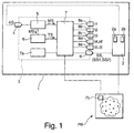
- Fig. 1 shows a schematic block diagram of an embodiment of the power supply according to the invention for a plasma process (plasma power supply).
- the plasma power supply 1 according to Fig. 1 has first the actual power source 2 for supplying the plasma process PP with a DC voltage or AC voltage and an arc discharge detection device 3, which interacts for detecting arc charges in the plasma process PP signaling with the power source 2 within the plasma power supply 1.
- the arc discharge detection device 3 has a first input 4 for a characteristic KG of the power source 2.
- the parameter KG can be a voltage or a current, ie an electrical parameter, wherein a voltage drop or an increase in the current at the power source 2 indicates that an arc discharge takes place in the plasma process PP or at least is emerging.
- the measurement of a performance parameter may also be meant here, as it is used above all in HF (high-frequency) plasma power supplies, for example a forward power P I and a reverse power P R. It is also possible to use an external characteristic or combinations of characteristics for arc discharge detection.
- the line source 2 comprises first and second arc discharge cancellation circuits 2a, 2b, which will be discussed in greater detail below.
- the arc discharge detection device 3 further comprises a monitoring unit 5, which is connected by signal technology to the input 4.
- the arc discharge detection device 3 has a timer unit 6 and a control unit 7 which cooperates with a storage means 7a, ie can access it.
- the control unit 7 has as shown in FIG Fig. 1 Further inputs 8a-e and an output 9 via the output 9, the control unit 7 and thus the arc discharge detection device 3 with the power source 2 already mentioned signal technology connected.
- Corresponding connections also exist between the monitoring unit 5 and the timer unit 6 as well as from the monitoring unit 5 and the timer unit 6 to the control unit 7.
- control unit 7 also has a sensor arrangement 7b for determining process parameters of the plasma process PP or is connected to such an arrangement in operative connection with the plasma process PP.
- the sensor arrangement 7b can additionally or alternatively also be used for the detection of arc discharges. It may be assigned to the monitoring unit 5 for this purpose.
- the monitoring unit 5 of the arc-detection device 3 is designed to monitor the electrical characteristic KG of the power source 2 entered at 4, for example by comparing it with a reference or threshold value (not shown), which is familiar to a person skilled in the art.
- the monitoring unit 5 may in particular be designed to detect a drop in the voltage of the power source 2 or an increase in the current of the power source 2 by comparison with a corresponding reference value, which accordingly indicates the presence or the occurrence of an arc discharge of the plasma process.
- the monitoring unit 5 is furthermore designed to generate a corresponding monitoring signal MS upon detection of an arc discharge, as described above, and in particular to output it to the timer unit 6. Furthermore, when the arc discharge is detected, the output of the monitoring signal MS also occurs to the control unit 7, as in FIG Fig. 1 shown.
- the term "generating" a signal without restricting generality indicates that the signal in question is switched to a high logic level ("1").
- the inventive idea can also be realized by means of alternative signal forms, in particular by the signals in question being used in their operation Generation are at least partially switched to a low logic level. This will be explained below with reference to the FIG. 2 discussed in more detail.
- the timer unit 6 is designed in particular to determine a time which has elapsed since the monitoring signal MS was generated by the monitoring unit 5 and to output the time signal TS to the control unit 7, as in FIG Fig. 1 shown.
- the control unit 7 in accordance with the monitoring signal MS of the monitoring unit 5 and the time signal TS of the timer unit 6 is known whether and, optionally, since when in the plasma process an arc discharge takes place or is in the process of development.
- the control unit 7 is in turn configured to generate at least one control signal SS depending on the applied monitoring signal MS and the time elapsed in accordance with the time signal TS since detection of an arc discharge and via the output 9 for controlling the plasma power supply 1 with respect to a respective one Issue countermeasure for suppressing the arc discharge to the power source 2.
- the control signal SS may in particular be a signal by means of which switching off or reversing the polarity of the power source 2 can be effected so as to suppress (erase) a detected arc discharge of the plasma process in a manner known per se.
- the already mentioned arc discharge-extinguishing circuits 2a, 2b are used in the power source 2, which, with appropriate activation by the at least one control signal SS, provide for switching off or reversing the power source 2.
- the timer unit 6 is furthermore designed, in particular, to determine a time which has elapsed since the at least one control signal SS was generated by the control unit 7.
- one of the timer unit 6 functionally corresponding unit can also be integrated directly into the control unit 7.
- the control unit 7 is specially designed to generate a first control signal SS1 for a to generate the first countermeasure and output via the output 9 to the power source 2 and the first arc discharge cancellation circuit 2a, respectively, when the monitoring unit 5 outputs the monitoring signal MS indicating the detection of an arc discharge.
- the first control signal SS1 is preferably output only after a predetermined first reaction time t5, which is indicated by the time signal TS of the timer unit 6, expires.
- a "countermeasure” can either be the switching off of the power source 2, ie an interruption of the plasma power supply, or a reversal of the polarity of the power source 2 by means of an arc discharge circuit 2a, 2b, in order to delete the arc discharge more efficiently in this way.
- the first reaction time t5 can be predetermined either via the input 8e of the arc discharge detection device 3 according to the invention, as in FIG FIG. 1 represented, for example by a user by means of a suitable input device (not shown).
- setting of the first reaction time t5 can also take place as a function of process parameters of the plasma process PP, which are determined by means of the sensor arrangement 7b and transmitted to the control unit 7.
- the variable first reaction time t5 it is possible to work towards an optimal processing result of the plasma process PP.
- the arc discharge previously detected and indicated by the monitoring signal MS is no longer present, this may mean that the detected arc discharge was a self-extinguishing arc discharge, ie a short arc.
- a response to such a short arc also reacts with a corresponding first countermeasure, which will be described below on the basis of FIG Fig. 2 will be discussed in more detail.
- the first countermeasure is carried out during a time duration t2, which in the present case is also referred to as the second time, and which can be predetermined via the input 8b, that is to say is adjustable. Subsequently, ie after completion of the first countermeasure, the arc discharge detection device 3 according to the invention waits in accordance with the control unit 7 during a delay time t1 which can be set via the input 8a, before the characteristic KG of the plasma process PP is checked again by the monitoring unit 5.
- this second control signal SS2 according to the invention, a second countermeasure for suppressing the arc discharge, which is different from the first countermeasure according to the present exemplary embodiment, is already described in detail above.
- the first and second countermeasures advantageously differ with respect to their respective implementation time, wherein in particular the adjustable second time t2, during which the first countermeasure is effected by the control signal SS1, is shorter than an adjustable third time t3, while the second countermeasure the control signal SS2 is effected.
- the second countermeasure is performed according to the first countermeasure only after elapse of a corresponding second reaction time t5 ', in order to optimize in this way a processing result of the plasma process PP.
- the control unit 7 After an arc discharge has been detected again after expiration of the delay time t1, the control unit 7 generates the second control signal SS2 only after expiration of the second reaction time t5 '.
- the second reaction time t5 ' may also be adjustable automatically or by a user, ie via the input 8e, in accordance with the first reaction time t5.
- the adjustable delay time or first time t1 and the adjustable second and third times t2, t3 are as shown in FIG Fig. 1 - As already mentioned - via respective inputs 8a - c in the control unit 7 on and thus specifiable. Alternatively, however, all these times can also be set automatically as a function of process parameters of the plasma process PP determined by the sensor arrangement 7b, as has already been described above by way of example.
- the fourth input 8d of the control unit 7 in Fig. 1 are still fourth times t4, t4 'on or predeterminable, to the below in explanation of the Fig. 2 will be discussed in detail.
- These inputs and all of the above-mentioned inputs can be stored together with standard default settings for the corresponding quantities in the memory means 7a.
- the storage means 7a is a non-volatile memory, so that the corresponding inputs or settings are retained even in the absence of power supply.
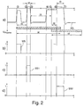
- Fig. 2 shows a timing diagram for signals within the plasma power supply 1 from Fig. 1 according to an embodiment of the present invention.
- the Fig. 2 is subdivided into four parts a) to d), wherein part a) exemplarily shows the signal curve of the electrical parameter KG (cf. Fig. 1 ), Part b) a signal waveform of the monitoring signal MS, part c) represents a waveform of the first control signal SS1 and part d) a waveform of the second control signal SS2.
- the time and U plasma is a plasma voltage of the considered plasma process, in the present case with a power source 2 (FIG. Fig. 1 ) supplied voltage is equivalent.
- Fig. 2 can be seen, it comes in 1 to a voltage dip of the plasma process, which is caused by an arc discharge. In the present case, this is a short arc that automatically goes out within a time t ⁇ t5, as in Fig. 2 in a) can be seen.
- the control unit 7 ( Fig. 1 ) at time 2 for a time t2, that is, until time 3, a reverse polarity of the plasma voltage by the first arc discharge cancellation circuit 2a. Waveforms of the corresponding control signals are in Fig. 2 to be taken from b) and c).
- the second control signal SS2 1 generated at the time 6 and output. This happens during a third time t3, where t3> t2, as well as the Fig. 2 can be seen in the upper area.
- Fig. 2 at a) symbolically by means of hatched bars further times or time intervals t4, t4 'are shown, which are also referred to as fourth times and whose value or duration via the already mentioned fourth input 8d of the control unit 7 in accordance Fig. 1 can be specified or predetermined.
- the fourth times of t4, t4 can also be determined automatically as a function of process parameters of the plasma process PP (FIG. Fig. 1 ) are adjusted or adjusted in order to achieve an optimal processing result in this way.
- the second time t2, during which the invention responds to a detected short arc is in the range of 0.01 to 10 ⁇ s. Accordingly, the third time t3 is greater than the second time t2, ie, t3> t2. As already stated, for the fourth times t4, t4> t1, t5 and t4 '> t1, t5'.
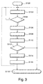
- Fig. 3 shows a flowchart for illustrating an embodiment of the method according to the invention for operating a plasma process.
- the method according to the invention begins with step S100.
- step S102 the monitoring of the electrical parameter, ie the voltage, the current or the power or an external signal, as already described in detail above takes place.
- step S104 it is checked in step S104 whether the occurrence of an arc discharge can be detected on the basis of the parameter monitored in step S102. If this is not the case (n), the method returns to step S102. If, however, the query in step S104 is affirmative (j), during the subsequent step S106 first the first reaction time is waited, as described above. Subsequently, in step S108, the corresponding control signal is generated for effecting the first countermeasure for a predetermined (second) time (unless a possibly previously initialized time interval for blocking responses to a short arc is active, not shown). Subsequently, in step S110, the lapse of the delay time is awaited.
- step S112 If, in a following step S112, an arc discharge is still detected (j), it is probably a hard arc, and after waiting for the second reaction time (step S114), a corresponding second countermeasure takes place in step S116 for a predetermined (third) time that is, an interruption or reversal of the plasma power supply (unless a possibly previously initialized time interval is active for blocking responses to a hard-arc (fourth time interval)). Subsequently, the process ends in step S118 or proceeds to step S102 (broken line in FIG Fig. 3 ).
- step S112 If the query in step S112 is negative, that is, after the delay time has elapsed, there is no more arc discharge or none originated new arc discharge, the process immediately ends with step S118 or proceeds to step S102 (dot-dash line in FIG Fig. 3 ).
- Embodiments of the present invention are applicable to plasma power supplies that provide DC power to a plasma as described in the examples.
- the invention is also applicable to plasma power supplies that provide an AC voltage to the plasma.
- the respective time can also be set automatically, for example, depending on the rate of the detected short or hard arcs over a predefinable time period - as already described in detail above. It may also be variable in response to one or more external signals applied to one or more input terminals (not shown) of the plasma power supply to be user-integrated in its measurements or controls, eg, a signal indicates a gas pressure or a type of gas mixture in the plasma process PP and according to the sensor arrangement 7b according to Fig. 1 can be determined.
- the arc discharge detection device for this purpose has the already described storage means 7a for storing one or more sets of preset parameters, which set the adjustable times and threshold values required for evaluating the characteristic to meaningful values, so that operation without delay is possible.
- an embodiment of the arc discharge detection device according to the invention has a possibility for the user to enter or load and store such data records as is provided, for example, via the described inputs 8a-e in connection with the storage means 7a.
- the storage means 7a is designed for this purpose as a non-volatile memory, which stores the data records even when the arc discharge detecting means is completely disconnected from each power supply.
- a further embodiment of the plasma power supply according to the invention preferably in the memory means 7a - one or more sets of preset parameters that set the adjustable times and thresholds to meaningful values, so that operation without delay is possible.
- the plasma power supply analogous to the arc discharge detection device described in detail above has a way to store such records by the user.
- these data sets are stored in a nonvolatile memory which stores the data even if the plasma power supply is completely disconnected from each power supply.
- a warning message including a device according to the invention in addition to said input means also corresponding output or display means (not shown). for issuing the warning message.
- the monitored parameter is - as stated - preferably an electrical characteristic, as described in the examples. However, it can also be any other suitable parameter from the plasma process sector.
Abstract
Description
Die Erfindung betrifft ein Verfahren zum Erkennen von Bogenentladungen in einem Plasmaprozess, bei dem zum Erkennen auftretender Bogenentladungen in dem Plasma mindestens eine Kenngröße des Plasmaprozesses überwacht wird und bei dem nach Erkennen einer Bogenentladung eine erste Gegenmaßnahme zum Unterdrücken von Bogenentladungen durchgeführt wird.The invention relates to a method for detecting arc discharges in a plasma process, in which at least one parameter of the plasma process is monitored for detecting occurring arc discharges in the plasma and in which, after detecting an arc discharge, a first countermeasure for suppressing arc discharges is performed.
Weiterhin betrifft die vorliegende Erfindung eine Bogenentladungs-Behandlungseinrichtung zum Erkennen von Bogenentladungen in einem Plasmaprozess anhand mindestens einer Kenngröße des Plasmaprozesses, aufweisend: eine Überwachungseinheit zum Überwachen der mindestens einen Kenngröße, die zum Erzeugen und Ausgeben eines Überwachungssignals bei Erkennen einer Bogenentladung ausgebildet ist; und eine Steuereinheit, die dazu ausgebildet ist, in Abhängigkeit von dem Überwachungssignal wenigstens ein Steuersignal zum Steuern einer jeweiligen Gegenmaßnahme zum Unterdrücken der Bogenentladung zu erzeugen.Furthermore, the present invention relates to an arc discharge treatment device for detecting arc discharges in a plasma process based on at least one characteristic of the plasma process, comprising: a monitoring unit for monitoring the at least one characteristic, which is designed to generate and output a monitoring signal upon detection of an arc discharge; and a control unit configured to generate, in response to the monitoring signal, at least one control signal for controlling a respective countermeasure for suppressing the arc discharge.
Darüber hinaus betrifft die vorliegende Erfindung auch eine Plasma-Leistungsversorgung zum Versorgen eines Plasmaprozesses.Moreover, the present invention also relates to a plasma power supply for supplying a plasma process.
Plasmaprozesse kommen beispielsweise in Plasmabearbeitungs- und Beschichtungsvorrichtungen vor. Mit Plasma kann weiterhin geätzt oder geascht werden. Ein sehr häufiger Plasmaprozess ist das so genannte Sputtern, bei dem mittels beschleunigter Ionen aus dem Plasma von einem Target Atome abgetragen werden, die sich auf einem Substrat ablagern. Beim Sputtern werden häufig reaktive Gase zugesetzt, um Verbundstoffe wie z.B. Al2O3 auf dem Substrat abzulagern Diese Art des Sputtens nennt man reaktives Sputtern. Beim reaktiven Sputtern kommt es zur Bildung von isolierenden Schichten auch auf dem Target. Die Ionen, die auf das Target beschleunigt werden, laden solche isolierenden Schichten auf. Übersteigt die Feldstärke einer so aufgeladenen isolierenden Schicht die Durchbruchfeldstärke, so kommt es zu Bogenentladungen, so genannten Arcs. Diese können kurz und selbstverlöschend sein (so genannte Short- oder Mikro-Arcs) oder aber lang andauernd und sehr energiereich sein (so genannte Hard-Arcs). Short-Arcs verursachen zumeist nur einen sehr geringen Schaden und können für viele Prozesse (z.B. Glasbeschichtung) zugelassen werden. Hard-Arcs führen in der Regel zur Zerstörung des Targets und zu nicht tolerierbaren Fehlstellen auf dem Substrat und werden daher in der Regel durch entsprechende Gegenmaßnahmen, wie nachfolgend beschrieben.Plasma processes occur, for example, in plasma processing and coating equipment. With plasma can continue etched or be erased. A very common plasma process is the so-called sputtering, in which atoms are removed from a target by means of accelerated ions from the plasma, which deposit on a substrate. During sputtering, reactive gases are often added to deposit composites such as Al 2 O 3 on the substrate. This type of sputtering is called reactive sputtering. In reactive sputtering, insulating layers also form on the target. The ions that are accelerated onto the target charge such insulating layers. If the field strength of such a charged insulating layer exceeds the breakdown field strength, arcing occurs, so-called arcs. These can be short and self-extinguishing (so-called short or micro-arcs) or long lasting and very energetic (so-called hard arcs). Short arcs usually cause very little damage and can be approved for many processes (eg glass coating). Hard arcs usually lead to the destruction of the target and to intolerable defects on the substrate and are therefore usually countermeasures, as described below.
Um größeren Schaden von einer Sputteranlage fernzuhalten, wird die Stromzufuhr der Plasma-Leistungsversorgung nach dem Auftreten eines Hard-Arcs, kurzzeitig unterbrochen. Alternativ kann auch die Spannung an der Plasmakammer kurzgeschlossen oder umgepolt werden. Um die vorstehend genannten Maßnahmen zur Unterdrückung von Bogenentladungen einleiten zu können, sind für die Leistungsversorgung von Plasmaprozessen Einrichtungen zur Bogenentladungs-Erkennung oder Arc-Erkennung sowie zur Löschung der Bogenentladungen erforderlich und bilden oft einen Bestandteil der Plasmastromversorgung.To avoid major damage from a sputtering system, the power supply of the plasma power supply is briefly interrupted after the occurrence of a hard arc. Alternatively, the voltage at the plasma chamber can be short-circuited or reversed. In order to initiate the abovementioned measures for suppressing arc discharges, devices for the arc discharge detection or arc detection and for the cancellation of the arc discharges are required for the power supply of plasma processes and often form part of the plasma power supply.
Da eine Unterbrechung der Plasma-Leistungsversorgung bzw. ein Umpolen derselben immer mit einer Beeinträchtigung des Durchsatzes des Plasmaprozesses verbunden ist und da es sich bei den erwähnten Short-Arcs um selbstverlöschende Bogenentladungen handelt, ist es eine weit verbreitete Ansicht, dass beim Betreiben eines Plasmaprozesses hinsichtlich Short-Arcs vorteilhafter Weise keine Gegenmaßnahmen ergriffen werden sollten. Da jedoch auch selbstverlöschende Arcs sich negativ auf ein Bearbeitungsergebnis des Plasmaprozesses auswirken und sich darüber hinaus ohne entsprechende Gegenmaßnahmen zu Hard-Arcs entwickeln können, hat sich ein derartiger Ansatz als nachteilig erwiesen.Since interruption of the plasma power supply or polarity reversal thereof is always associated with a deterioration in the throughput of the plasma process, and since the short arcs mentioned are self-extinguishing arc discharges, it is a widespread view that when operating a plasma process Short arcs advantageously no countermeasures should be taken. However, since self-extinguishing arcs have a negative effect on a processing result of the plasma process and can also develop without appropriate countermeasures to hard arcs, such an approach has proved to be disadvantageous.
Bei dem vorbekannten Verfahren ist demnach insbesondere als nachteilig anzusehen, dass auf selbstverlöschende Bogenentladungen überhaupt nicht reagiert wird. Wie bereits vorstehend angesprochen, ist dies mit den steigenden Anforderungen an Überarbeitungsqualität bei Plasmaprozessen, beispielsweise an die Qualität einer Beschichtung, nicht vereinbar.In the prior art method is therefore considered to be particularly disadvantageous that is not reacted to self-extinguishing arc discharges. As already mentioned above, this is incompatible with the increasing demands on quality of revision in plasma processes, for example on the quality of a coating.
Wenn eine Reaktion auf Short-Arcs jedoch in genau derselben Weise hinsichtlich Dauer und Intensität erfolgte wie bei Hard-Arcs, die naturgemäß häufig stärkere Gegenmaßnahmen erfordern, wäre die Plasma-Leistungsversorgung während unangemessen langer Zeiträume nicht aktiv, was zu einer deutlichen Verringerung der Bearbeitungsrate führen würde.However, if a response to short arcs occurred in exactly the same way in terms of duration and intensity as hard arcs, which by nature often require stronger countermeasures, plasma power would be inactive for unduly long periods, resulting in a significant reduction in processing rate would.
Aus der
Insbesondere erfolgt dabei keine echte Unterscheidung zwischen Short-Arcs und Hard-Arcs, so dass beim Auftreten eines Hard-Arc wiederholt immer nur mit möglichst kurzen Unterbrechungen des Leistungsflusses reagiert wird, die jedoch einen Hard-Arc unter Umständen nicht löschen können und zu einer wiederholten Lieferung von Leistung in den Hard-Arc führen, wobei der Leistungsflusses unmittelbar nach erkennen des Hard-Arc wieder unterbrochen wird. Dies wirkt sich auf die Dauer negativ auf eine Bearbeitungsrate des Plasmaprozesses aus, wenn ein Hard-Arc auf diese Weise nicht sicher gelöscht werden kann.In particular, there is no real distinction between short arcs and hard arcs, so that the occurrence of a hard-arc repeatedly reacts only with the shortest possible interruptions of the power flow, which, however, may not delete a hard-arc and a repeated Deliver power to the hard-arc, breaking the power flow immediately after the Hard-Arc detects it. This has a negative effect on a processing rate of the plasma process in the long run, if a hard-arc can not be safely deleted in this way.
Der Erfindung liegt die Aufgabe zugrunde, ein Verfahren, eine Bogenentladungs-Erkennungseinrichtung und eine Plasma-Leistungsversorgung der jeweils eingangs genannten Art dahingehend weiterzuentwickeln, dass sie steigenden Anforderungen an die Bearbeitungsqualität gerecht werden, ohne dass eine Bearbeitungsrate über Gebühr beeinträchtigt wird.The invention has for its object to further develop a method, an arc discharge detection device and a plasma power supply of each type mentioned in that they meet increasing demands on the quality of processing, without a processing rate is excessively impaired.
Gemäß einem ersten Aspekt der vorliegenden Erfindung wird diese Aufgabe bei einem Verfahren der eingangs genannten Art dadurch gelöst, dass nach Beendigung der ersten Gegenmaßnahme während einer variablen Verzögerungszeit abgewartet und anschließend in dem Fall, dass nach Ablauf der variablen Verzögerungszeit eine Bogenentladung erkannt wird, eine zweite Gegenmaßnahme zum Unterdrücken von Bogenentladungen durchgeführt wird.According to a first aspect of the present invention, this object is achieved in a method of the type mentioned in that after completion of the first countermeasure during a variable delay time and then in the event that after the variable delay time, an arc discharge is detected, a second Countermeasure for suppressing arc discharges is performed.
Gemäß einem zweiten Aspekt der vorliegenden Erfindung wird die Aufgabe bei einer Bogenentladungs-Erkennungseinrichtung der eingangs genannten Art dadurch gelöst, dass die Steuereinheit dazu ausgebildet ist, nach Beendigung einer ersten Gegenmaßnahme während einer variablen Verzögerungszeit abzuwarten und nach Ablauf der variablen Verzögerungszeit in Abhängigkeit von dem Überwachungssignal ein Steuersignal zum Steuern einer zweiten Gegenmaßnahme zu erzeugen.According to a second aspect of the present invention, the object is achieved in an arc detection device of the type mentioned above in that the control unit is adapted to wait after completion of a first countermeasure during a variable delay time and after the expiration of the variable Delay time in response to the monitoring signal to generate a control signal for controlling a second countermeasure.
Im Kontext der vorliegenden Beschreibung bedeutet der Ausdruck "variabel", dass ein entsprechender Wert, wie eine zeitliche Dauer, nicht fest vorgegeben beziehungsweise fest eingestellt sondern im Verlaufe eines Verfahrens oder bei der Verwendung einer Vorrichtung veränderbar ist, sei es automatisch in Abhängigkeit von bestimmten Prozessparametern oder explizit durch Eingabe (Steuerung) seitens eines Anwenders. Darin liegt ein besonderer Vorteil dieser Erfindung. Vorbekannte Bogenentladungs-Erkennungseinrichtungen waren in dieser Hinsicht beschränkt und boten dem Anwender keine Möglichkeiten, Zeiten - wie insbesondere die Verzögerungszeit - variabel zu einzustellen. Mit der vorliegenden Erfindung hat der Anwender die Möglichkeit, die Bogenentladungs-Erkennungseinrichtung in vielfacher Hinsicht besser auf seine Prozesse abzustimmen und die Bearbeitungsrate sowie die Bearbeitungsqualität gleichzeitig hoch zu halten.In the context of the present description, the term "variable" means that a corresponding value, such as a time duration, is not fixed or fixed, but changeable in the course of a process or the use of a device, be it automatically depending on certain process parameters or explicitly by input (control) by a user. This is a particular advantage of this invention. Previously known arc discharge detection devices were limited in this regard and offered the user no opportunities to variably set times - in particular the delay time. With the present invention, the user has the opportunity to tune the arc discharge detection device in many respects better to its processes and to keep the processing rate and the processing quality at the same time high.
Gemäß einem dritten Aspekt der vorliegenden Erfindung wird die Aufgabe bei einer Plasma-Leistungsversorgung der genannten Art gelöst durch eine Bogenentladungs-Erkennungseinrichtung nach dem zweiten Aspekt der vorliegenden Erfindung, wobei die Plasma-Leistungsversorgung durch die Steuereinheit der Bogenentladungs-Erkennungseinrichtung steuerbar ist. Entsprechend ist in Weiterbildung des erfindungsgemäßen Verfahrens vorgesehen, dass das Verfahren zum Steuern des Betriebs einer Plasma-Leistungsversorgung eingesetzt wird.According to a third aspect of the present invention, the object in a plasma power supply of the type mentioned is achieved by an arc discharge detection device according to the second aspect of the present invention, wherein the plasma power supply is controllable by the control unit of the arc discharge detection device. Accordingly, it is provided in a further development of the method according to the invention that the method for controlling the operation of a plasma power supply is used.
Nach einem Grundgedanken der vorliegenden Erfindung wird somit in jedem Fall, d.h. auch im Falle von selbstverlöschenden Bogenentladungen eine erste Gegenmaßnahme zum Unterdrücken von Bogenentladungen bewirkt, wodurch die Erfindung steigenden Anforderungen an die Bearbeitungsqualität bei Plasmaprozessen gerecht wird. Allerdings wird eine derartige Gegenmaßnahme erfindungsgemäß nur dann vorgenommen oder eingeleitet, wenn zuvor tatsächlich eine (selbstverlöschende) Bogenentladung erkannt wurde. Anschließend wird nach Beendigung der ersten Gegenmaßnahme während einer variablen Verzögerungszeit, die vorliegend auch als "erste Zeit" bezeichnet wird und die bei bevorzugten Ausgestaltungen der vorliegenden Erfindung automatisch in Abhängigkeit von Prozessparametern des Plasmaprozesses oder alternativ durch einen Anwender einstellbar sein kann, abgewartet, so dass auf diese Weise zwischen Short-Arcs und Hard-Arcs unterschieden werden kann. Anschließend kann erfindungsgemäß mit der zweiten Gegenmaßnahme auf einem noch immer anliegenden Arc (Hard-Arc) reagiert werden.According to a basic idea of the present invention, a first countermeasure for suppressing arc discharges is thus effected in each case, ie also in the case of self-extinguishing arc discharges, whereby the invention meets increasing demands on the processing quality in plasma processes. However, according to the invention, such a countermeasure is only undertaken or initiated if a (self-extinguishing) arc discharge has actually been detected previously. Thereafter, after completion of the first countermeasure during a variable delay time, herein also referred to as "first time", which in preferred embodiments of the present invention may be automatically adjustable depending on process parameters of the plasma process or alternatively by a user, it is awaited can be distinguished in this way between short arcs and hard arcs. Subsequently, according to the invention, the second countermeasure can be reacted to a still applied arc (hard arc).
Im Zuge entsprechende Weiterbildungen der vorliegenden Erfindung sind die ersten und zweiten Gegenmaßnahmen hinsichtlich ihrer Dauer, Intensität oder dergleichen zum Löschen von Short-Arcs beziehungsweise Hard-Arcs ausgebildet.In the course of appropriate developments of the present invention, the first and second countermeasures are designed with regard to their duration, intensity or the like for erasing short arcs or hard arcs.
Bei der überwachten Kenngröße kann es sich in Weiterbildung sowohl des erfindungsgemäßen Verfahrens als auch der erfindungsgemäßen Bogenentladungs-Erkennungseinrichtung um eine elektrische Kenngröße des Plasmaprozesses handeln, wie eine Spannung oder eine Stromstärke.In the monitored parameter, both the method according to the invention and the arc discharge detection device according to the invention may be an electrical parameter of the plasma process, such as a voltage or a current intensity.
Es ist erfindungsgemäß insbesondere auch möglich, die erste Gegenmaßnahme nach Maßgabe einer Überwachung einer ersten Kenngröße des Plasmaprozesses und die zweite Gegenmaßnahme nach Maßgabe einer Überwachung einer zweiten, von der ersten Kenngröße verschiedenen Kenngröße des Plasmaprozesses zu steuern.According to the invention, it is also possible in particular to control the first countermeasure in accordance with a monitoring of a first parameter of the plasma process and the second countermeasure in accordance with a monitoring of a second parameter of the plasma process that is different from the first parameter.
In Weiterbildung des erfindungsgemäßen Verfahrens ist vorgesehen, dass als erste Gegenmaßnahme ein Unterbrechen oder ein Umpolen der Plasma-Leistungsversorgung durchgeführt wird. Dabei kann die erste Gegenmaßnahme insbesondere während einer zweiten Zeit durchgeführt werden, die darüber hinaus wie die erste Zeit variabel sein kann.In a development of the method according to the invention, it is provided that the first countermeasure is an interruption or a reversal of the polarity of the plasma power supply. In this case, the first countermeasure can be carried out, in particular, during a second time which, in addition, may be variable like the first time.
Im Zuge einer entsprechenden Ausgestaltung der erfindungsgemäßen Plasma-Leistungsversorgung ist vorgesehen, dass als erste Gegenmaßnahme nach Maßgabe des ersten Steuersignals die Plasma-Leistungsversorgung während einer bestimmten Zeit abschaltbar oder umpolbar ist, insbesondere während der zweiten Zeit. Die Steuereinheit der erfindungsgemäßen Bogenentladungs-Erkennungseinrichtung ist daher im Zuge einer entsprechenden Weiterbildung zum Ausgeben eines ersten Steuersignals zum Steuern der ersten Gegenmaßnahme während einer zweiten Zeit ausgebildet.In the course of a corresponding embodiment of the plasma power supply according to the invention, provision is made for the plasma power supply to be switched off or reversible for a specific time as a first countermeasure in accordance with the first control signal, in particular during the second time. The control unit of the arc discharge detection device according to the invention is therefore designed in the course of a corresponding development for outputting a first control signal for controlling the first countermeasure during a second time.
Um - wie gesagt - eine möglichst geringe Beeinträchtigung der Bearbeitungsrate des Plasmaprozesses zu gewährleisten, sieht eine andere Weiterbildung des erfindungsgemäßen Verfahrens vor, dass die erste Gegenmaßnahme zur Unterdrückung/Löschung von Short-Arcs nur kurzzeitig durchgeführt wird, d.h. dass die zweite Zeit zwischen 0,01 und 10 µs beträgt.In order to ensure the least possible impairment of the processing rate of the plasma process, as already stated, another development of the method according to the invention provides that the first countermeasure for the suppression / erasure of short arcs is carried out only briefly, i. the second time is between 0.01 and 10 μs.
Gemäß einer entsprechenden Weiterbildung der erfindungsgemäßen Bogenentladungs-Erkennungseinrichtung ist vorgesehen, dass die zweite Zeit einstellbar ist und insbesondere zwischen 0,01 und 10 µs beträgt.According to a corresponding development of the arc discharge detection device according to the invention it is provided that the second time is adjustable and in particular between 0.01 and 10 microseconds.
Vorteilhafter Weise kann bei einer Ausgestaltung des erfindungsgemäßen Verfahrens vorgesehen sein, dass als zweite Gegenmaßnahme ein Unterbrechen oder ein Umpolen der Plasma-Leistungsversorgung durchgeführt wird, wobei die zweite Gegenmaßnahme im Zuge einer anderen Weiterbildung des erfindungsgemäßen Verfahrens während einer dritten Zeit durchgeführt wird. In diesem Zusammenhang sieht eine weitere Ausgestaltung des erfindungsgemäßen Verfahrens vor, dass die dritte Zeit länger als die zweite Zeit ist und vorzugsweise mehr als 10 µs beträgt. Dabei kann die dritte Zeit ebenso wie die erste Zeit und die zweite Zeit variabel sein.Advantageously, it can be provided in one embodiment of the method according to the invention that as a second countermeasure interrupting or reversing the plasma power supply is carried out, wherein the second countermeasure is carried out in the course of another development of the method according to the invention during a third time. In this connection, a further embodiment of the method according to the invention provides that the third time is longer than the second time and is preferably more than 10 μs. The third time as well as the first time and the second time can be variable.
Eine entsprechende Weiterbildung der erfindungsgemäßen Plasma-Leistungsversorgung sieht vor, dass als zweite Gegenmaßnahme nach Maßgabe des zweiten Steuersignals die Plasma-Leistungsversorgung während einer weiteren vorbestimmten Zeit abschaltbar oder umpolbar ist, insbesondere während der dritten Zeit. Dabei kann die dritte Zeit in Weiterbildung der erfindungsgemäßen Bogenentladungs-Erkennungseinrichtung einstellbar sein, insbesondere auf Werte größer als die zweite Zeit.A corresponding development of the plasma power supply according to the invention provides that, as a second countermeasure in accordance with the second control signal, the plasma power supply can be switched off or reversed for a further predetermined time, in particular during the third time. In this case, the third time can be adjustable in development of the arc discharge detection device according to the invention, in particular to values greater than the second time.
Gemäß einer anderen Ausgestaltung des erfindungsgemäßen Verfahrens kann vorgesehen sein, dass während der Verzögerungszeit oder ersten Zeit keine Reaktion auf weitere erkannte Bogenentladungen erfolgt. Treten nämlich während der Zeit nach dem Erkennen einer ersten Bogenentladung bis zum Ablauf der genannten ersten Zeit noch weitere Bogenentladungen auf, brauchen diese erfindungsgemäß nicht berücksichtigt zu werden. Sollte nämlich - wie vorstehend beschrieben - nach Ablauf der ersten Zeit die Bogenentladung noch immer anliegen, wird diese ohnehin als Hard-Arc behandelt und mit einer entsprechend angepassten zweiten Gegenmaßnahme unterdrückt. Wenn jedoch die erste bekannte Bogenentladung nach Ablauf der ersten Zeit nicht mehr anliegt, bereinigt das gemäß einer Ausgestaltung der vorliegenden Erfindung vorgesehene kurze Abschalten bzw. Umpolen (d.h. die erste Gegenmaßnahme) auch alle "Unreinheiten" der zwischenzeitlich weiter aufgetretenen Bogenentladungen.According to another embodiment of the method according to the invention, it can be provided that during the delay time or first time, there is no reaction to further detected arc discharges. If, in addition, further arc discharges occur during the time after the detection of a first arc discharge until the end of the said first time, these need not be considered according to the invention. If, as described above, the arc discharge is still present after the first time has elapsed, it is anyway treated as a hard arc and suppressed with a correspondingly adapted second countermeasure. However, if the first known arc discharge is not applied after the first time has elapsed, the brief turn-off or reversal (ie the first countermeasure) provided in accordance with one embodiment of the present invention also eliminates all "impurities" in the arc discharges that have occurred in the meantime.
Um das erfindungsgemäße Verfahren hinsichtlich des Bearbeitungsdurchsatzes weiter zu verbessern, kann in Weiterbildung des erfindungsgemäßen Verfahrens auch vorgesehen sein, dass während einer jeweiligen vierten Zeit keine weiteren ersten und/oder zweiten Gegenmaßnahmen durchgeführt werden.In order to further improve the method according to the invention with regard to the processing throughput, it can also be provided in a development of the method according to the invention that during a respective fourth time no further first and / or second countermeasures are carried out.
Entsprechend kann in Weiterbildung der erfindungsgemäßen Bogenentladungs-Erkennungseinrichtung vorgesehen sein, dass die Steuereinheit dazu ausgebildet ist, das erste Steuersignal und/oder das zweite Steuersignal vor Ablauf einer jeweiligen vierten Zeit nicht erneut zu erzeugen. Dabei kann die vierte Zeit einstellbar sein.Accordingly, it can be provided in a further development of the arc discharge detection device according to the invention that the control unit is designed to not generate the first control signal and / or the second control signal again before the expiration of a respective fourth time. The fourth time can be adjustable.
Bei einer anderen Ausgestaltung der erfindungsgemäßen Bogenentladungs-Erkennungseinrichtung ist die vierte Zeit für die ersten und zweiten Gegenmaßnahmen unabhängig voneinander einstellbar. Das Einstellen der vierten Zeit beziehungsweise der vierten Zeiten kann - wie auch das Einstellen der Verzögerungszeit (ersten Zeit) sowie der zweiten und dritten Zeiten - alternativ in Abhängigkeit von Prozessparametern des Plasmaprozesses automatisch oder durch eine entsprechende Eingabe seitens eines Anwenders geschehen.In another embodiment of the arc discharge detection device according to the invention, the fourth time for the first and second countermeasures is independently adjustable. The setting of the fourth time or the fourth times can - as well as the setting of the delay time (first time) and the second and third times - alternatively done depending on process parameters of the plasma process automatically or by a corresponding input by a user.
Durch das Vorgeben bzw. Einstellen der vierten Zeit(en), innerhalb derer auf mehrere (zusätzlich) erkannte Arcs nicht reagiert wird, lässt sich die Bearbeitungsrate des Plasmaprozesses optimal anpassen und ggf. weiter erhöhen.By setting or setting the fourth time (s) within which unresponsive to several (additionally) recognized arcs, the processing rate of the plasma process can be optimally adapted and possibly further increase.
Eine andere Weiterbildung des erfindungsgemäßen Verfahrens zeichnet sich dadurch aus, dass die ersten und zweiten Gegenmaßnahmen von verschiedenen Bogenentladung-Löschungsschaltkreisen durchgeführt werden. Entsprechend kann in Weiterbildung der erfindungsgemäßen Bogenentladungs-Erkennungseinrichtung vorgesehen sein, dass diese getrennte Bogenentladung-Löschungsschaltkreise zum Bewirken der ersten und zweiten Gegenmaßnahmen aufweist. Auf diese Weise lässt sich auch hardwaremäßig eine optimal angepasste Reaktion auf unterschiedliche Typen von Bogenentladungen erreichen.Another development of the method according to the invention is characterized in that the first and second countermeasures are performed by different arc discharge-cancellation circuits become. Accordingly, it can be provided in a development of the arc discharge detection device according to the invention that it has separate arc discharge-cancellation circuits for effecting the first and second countermeasures. In this way, an optimally adapted reaction to different types of arc discharges can also be achieved in terms of hardware.
Des Weiteren kann bei einer anderen Ausgestaltung des erfindungsgemäßen Verfahrens vorgesehen sein, dass die ersten und zweiten Gegenmaßnahmen jeweils nach Ablauf einer variablen Reaktionszeit ab Erkennen einer Bogenentladung durchgeführt werden. Mit anderen Worten: die jeweilige Gegenmaßnahme wird nicht unmittelbar bei Erkennen einer Bogenentladung sondern erst nach Verstreichen der jeweiligen Reaktionszeit durchgeführt. Das Vorsehen einer solchen zusätzlichen variablen Reaktionszeit ist in Plasmaprozessen zum Erzielen eines optimalen Bearbeitungsergebnisses oftmals günstig.Furthermore, it can be provided in another embodiment of the method according to the invention that the first and second countermeasures are carried out in each case after expiration of a variable reaction time from detection of an arc discharge. In other words, the respective countermeasure is not performed immediately upon detection of an arc discharge but only after elapse of the respective reaction time. The provision of such an additional variable reaction time is often favorable in plasma processes for achieving an optimal processing result.
Bei einer entsprechenden Weiterbildung der erfindungsgemäßen Bogenentladungs-Erkennungseinrichtung ist vorgesehen, dass die Steuereinheit zum Veranlassen der ersten und zweiten Gegenmaßnahmen jeweils nach Ablauf einer variablen Reaktionszeit ab Erkennen einer Bogenentladung ausgebildet ist.In a corresponding development of the arc discharge detection device according to the invention, it is provided that the control unit is designed to initiate the first and second countermeasures each time a variable reaction time has elapsed from the detection of an arc discharge.
Weiterhin kann auch die jeweilige Reaktionszeit automatisch in Abhängigkeit von Prozessparametern des Plasmaprozesses oder durch einen Anwender einstellbar sein.Furthermore, the respective reaction time can also be set automatically as a function of process parameters of the plasma process or by a user.
Weitere Merkmale und Vorteile der Erfindung ergeben sich aus der nachfolgenden Beschreibung von Ausführungsbeispielen der Erfindung, anhand den Figuren der Zeichnung, die erfindungswesentliche Einzelheiten zeigen, und aus den Ansprüchen. Die einzelnen Merkmale können je einzeln für sich oder zu mehreren in beliebiger Kombination bei einer Variante der Erfindung verwirklicht sein.Further features and advantages of the invention will become apparent from the following description of embodiments of the invention, with reference to the figures of the drawing, which show details essential to the invention, and from the claims. The individual features can be realized individually for themselves or for several in any combination in a variant of the invention.
Bevorzugte Ausführungsbeispiele der Erfindung sind in der Zeichnung schematisch dargestellt und werden nachfolgend mit Bezug zu den Figuren der Zeichnung näher erläutert. Es zeigt:
- Fig. 1
- ein schematisches Blockschaltbild einer Ausgestaltung der erfindungsgemäßen Leistungsversorgung für einen Plasmaprozess;
- Fig. 2
- ein Zeitablaufdiagramm für Signale innerhalb der Plasma-Leistungsversorgung aus
Fig. 1 ; und - Fig. 3
- ein Flussdiagramm zur Darstellung einer Ausgestaltung des erfindungsgemäßen Verfahrens zum Erkennen von Bogenentladungen.
- Fig. 1
- a schematic block diagram of an embodiment of the power supply according to the invention for a plasma process;
- Fig. 2
- a timing diagram for signals within the plasma power supply
Fig. 1 ; and - Fig. 3
- a flowchart illustrating an embodiment of the inventive method for detecting arc discharges.
Dazu weist die Bogenentladungs-Erkennungseinrichtung 3 einen ersten Eingang 4 für eine Kenngröße KG der Leistungsquelle 2 auf. Wie dem Fachmann an sich geläufig ist, kann es sich bei der Kenngröße KG um eine Spannung oder einen Strom handeln, d.h. um eine elektrische Kenngröße, wobei ein Spannungsabfall bzw. eine Stromerhöhung an der Leistungsquelle 2 anzeigt, dass in dem Plasmaprozess PP eine Bogenentladung stattfindet oder zumindest im Entstehen begriffen ist. Auch die Messung einer Leistungs-Kenngröße kann hier gemeint sein, wie sie vor allem bei HF (Hochfrequenz)-Plasma-Leistungsversorgungen eingesetzt wird, beispielsweise einer Vorwärtsleistung PI und einer Rückwärtsleistung PR. Es ist auch möglich, eine externe Kenngröße oder Kombinationen von Kenngrößen zur Bogenentladungserkennung heranzuziehen.For this purpose, the arc
Die Leitungsquelle 2 umfasst erste und zweite Bogenentladung-Löschungsschaltkreise 2a, 2b, auf die weiter unten noch genauer eingegangen wird.The
Die Bogenentladungs-Erkennungseinrichtung 3 umfasst weiterhin eine Überwachungseinheit 5, die signaltechnisch mit dem Eingang 4 verbunden ist. Darüber hinaus weist die Bogenentladungs-Erkennungseinrichtung 3 eine Timer-Einheit 6 sowie eine Steuereinheit 7 auf, die mit einem Speichermittel 7a zusammenwirkt, d.h. auf dieses zugreifen kann. Die Steuereinheit 7 besitzt gemäß der Darstellung in
Darüber hinaus weist die Steuereinheit 7 noch eine Sensoranordnung 7b zum Bestimmen von Prozessparametern des Plasmaprozesses PP auf beziehungsweise ist mit einer solchen Anordnung in Wirkverbindung mit dem Plasmaprozess PP verbunden. Die Sensoranordnung 7b kann zusätzlich oder alternativ auch zur Erkennung von Bogenentladungen genutzt werden. Sie kann zu diesem Zweck der Überwachungseinheit 5 zugeordnet sein.In addition, the
Erfindungsgemäß ist die Überwachungseinheit 5 der Bogenentladungs-Erkennungseinrichtung 3 dazu ausgebildet, die bei 4 eingegebene elektrische Kenngröße KG der Leistungsquelle 2 zu überwachen, beispielsweise durch Vergleichen mit einem (nicht gezeigten) Referenz- oder Schwellwert, was dem Fachmann an sich geläufig ist. Somit kann die Überwachungseinheit 5 insbesondere dazu ausgebildet sein, einen Abfall der Spannung der Leistungsquelle 2 bzw. einem Anstieg des Stroms der Leistungsquelle 2 durch Vergleich mit einem entsprechenden Referenzwert zu erkennen, was dementsprechend das Vorhandensein oder die Entstehung einer Bogenentladung des Plasmaprozesses anzeigt. Die Überwachungseinheit 5 ist weiterhin dazu ausgebildet, bei Erkennen einer Bogenentladung, wie vorstehend beschrieben, ein entsprechendes Überwachungssignal MS zu erzeugen und insbesondere an die Timer-Einheit 6 auszugeben. Des Weiteren erfolgt die Ausgabe des Überwachungssignals MS bei Erkennen der Bogenentladung auch an die Steuereinheit 7, wie in
Es sei an dieser Stelle angemerkt, dass im Rahmen der vorliegenden Beschreibung der Begriff "Erzeugen" eines Signals ohne Beschränkung der Allgemeinheit angibt, dass das betreffende Signal auf einen hohen Logikpegel ("1") umgeschaltet wird. Wie der Fachmann erkennt, lässt sich der erfinderische Gedanke jedoch auch mittels alternativer Signalformen verwirklichen, insbesondere indem die betreffenden Signale bei ihrer Erzeugung zumindest teilweise auf einen niedrigen Logikpegel umgeschaltet werden. Hierauf wird weiter unten unter Bezugnahme auf die
Die Timer-Einheit 6 ist vorliegend insbesondere dazu ausgebildet, eine seit Erzeugung des Überwachungssignals MS durch die Überwachungseinheit 5 vergangene Zeit zu bestimmen und das Zeitsignal TS an die Steuereinheit 7 auszugeben, wie in
Die Steuereinheit 7 ist erfindungsgemäß ihrerseits dazu ausgebildet, in Abhängigkeit von dem anliegenden Überwachungssignal MS und der nach Maßgabe des Zeitsignals TS vergangenen Zeit seit Erkennen einer Bogenentladung wenigstens ein Steuersignal SS zu erzeugen und über den Ausgang 9 zum Steuern der Plasma-Leistungsversorgung 1 hinsichtlich einer betreffenden Gegenmaßnahme zur Unterdrückung der Bogenentladung an die Leistungsquelle 2 auszugeben. Dabei kann es sich bei dem Steuersignal SS insbesondere um ein Signal handeln, durch welches ein Abschalten oder ein Umpolen der Leistungsquelle 2 bewirkbar ist, um auf diese Weise in an sich bekannter Weise eine erkannte Bogenentladung des Plasmaprozesses zu unterdrücken (löschen). Dabei kommen in der Leistungsquelle 2 die bereits erwähnten Bogenentladung-Löschungsschaltkreise 2a, 2b zum Einsatz, die bei entsprechender Aktivierung durch das mindestens eine Steuersignal SS für ein Abschalten oder Umpolen der Leistungsquelle 2 sorgen.The
Die Timer-Einheit 6 ist vorliegend weiterhin insbesondere dazu ausgebildet, eine seit Erzeugung des wenigstens einen Steuersignals SS durch die Steuereinheit 7 vergangene Zeit zu bestimmen. Somit ist erfindungsgemäß bekannt, ob und gegebenenfalls seit wann bzw. bis wann durch die Steuereinheit 7 Gegenmaßnahmen zum Unterdrücken einer Bogenentladung in dem Plasmaprozess veranlasst werden/wurden. Alternativ kann eine der Timer-Einheit 6 funktional entsprechende Einheit auch direkt in die Steuereinheit 7 integriert sein.In the present case, the
Um in der Praxis ein sicheres Löschen sowohl von selbstverlöschenden Short-Arcs als auch von nicht selbstverlöschenden Hard-Arcs realisieren zu können, ohne dabei eine Bearbeitungsrate des Plasmaprozesses PP übermäßig zu beeinträchtigen, ist die Steuereinheit 7 speziell dazu ausgebildet, ein erstes Steuersignal SS1 für eine erste Gegenmaßnahme zu erzeugen und über den Ausgang 9 an die Leistungsquelle 2 beziehungsweise den ersten Bogenentladung-Löschungsschaltkreis 2a auszugeben, wenn die Überwachungseinheit 5 das Überwachungssignal MS, welches das Erkennen einer Bogenentladung anzeigt, ausgibt. Vorzugsweise wird das erste Steuersignal SS1 erst nach Ablauf einer vorgegebenen ersten Reaktionszeit t5, die durch das Zeitsignal TS der Timer-Einheit 6 angezeigt wird, ausgegeben. Mit anderen Worten: Wenn das Zeitsignal TS der Timer-Einheit 6 den Ablauf einer vorgegebenen Reaktionszeit anzeigt, gibt die Steuereinheit 7 über den Ausgang 9 das erste Steuersignal SS1 an die Leistungsquelle 2 beziehungsweise dem ersten Bogenentladung-Löschungsschaltkreis 2a aus, um auf diese Weise die erste Gegenmaßnahme zu bewirken. Dabei kann es sich bei einer "Gegenmaßnahme" entweder um das Abschalten der Leistungsquelle 2, d.h. eine Unterbrechung der Plasma-Leistungsversorgung, oder um ein Umpolen der Leistungsquelle 2 mittels eines Bogenentladung-Löschungsschaltkreises 2a, 2b handeln, um auf diese Weise die Bogenentladung noch effizienter löschen zu können.In order to be able to realize in practice a safe erasing of both self-extinguishing short arcs and non-self-extinguishing hard arcs without unduly impairing a processing rate of the plasma process PP, the
Die erste Reaktionszeit t5 kann im Rahmen der vorliegenden Erfindung entweder über den Eingang 8e der erfindungsgemäßen Bogenentladungs-Erkennungseinrichtung 3 vorgegeben werden, wie in
Die erste Gegenmaßnahme wird während einer zeitlichen Dauer t2 durchgeführt, die vorliegend auch als zweite Zeit bezeichnet wird und die über den Eingang 8b vorgebbar, das heißt einstellbar ist. Anschließend - also nach Beendigung der ersten Gegenmaßnahme - wartet die erfindungsgemäße Bogenentladungs-Erkennungseinrichtung 3 nach Maßgabe der Steuereinheit 7 während einer über den Eingang 8a einstellbaren Verzögerungszeit t1, bevor mittels der Überwachungseinheit 5 erneut die Kenngröße KG des Plasmaprozesses PP überprüft wird. Wenn entsprechend nach Ablauf der Verzögerungszeit t1 das Steuersignal MS weiterhin eine Bogenentladung anzeigt, d.h. MS = 1, erzeugt die Steuereinheit 7 (ggf. nach Ablauf einer zweiten Reaktionszeit t5'; siehe unten) ein zweites, von dem ersten Steuersignal SS1 verschiedenes, zweites Steuersignal SS2 und gibt dieses über den Ausgang 9 an die Leistungsquelle 2 beziehungsweise an den zweitem Bogenentladung-Löschungsschaltkreis 2b aus. Durch dieses zweite Steuersignal SS2 wird erfindungsgemäß eine zweite, gemäß dem vorliegenden Ausführungsbeispiel von der ersten Gegenmaßnahme verschiedene Gegenmaßnahme zum Unterdrücken der Bogenentladung bewirkt, wie weiter oben bereits ausführlich dargestellt. Mit anderen Worten: Wenn nach Ablauf der Verzögerungszeit t1 wiederum eine Bogenentladung erkannt wird, handelt es sich dabei wahrscheinlich um einen nicht selbstverlöschenden Hard-Arc, auf den mit einer speziellen zweiten Gegenmaßnahme reagiert wird. Dabei unterscheiden sich die ersten und zweiten Gegenmaßnahmen vorteilhafter Weise hinsichtlich ihrer jeweiligen Durchführungszeit, wobei insbesondere die einstellbare zweite Zeit t2, während der die erste Gegenmaßnahme durch das Steuersignal SS1 bewirkt ist, kürzer ist als eine einstellbare dritte Zeit t3, während der die zweite Gegenmaßnahme durch das Steuersignal SS2 bewirkt ist.The first countermeasure is carried out during a time duration t2, which in the present case is also referred to as the second time, and which can be predetermined via the
Auch die zweite Gegenmaßnahme wird entsprechend der ersten Gegenmaßnahme erst nach Verstreichen einer entsprechenden zweiten Reaktionszeit t5' durchgeführt, um auf diese Weise ein Bearbeitungsergebnis des Plasmaprozesses PP zu optimieren. Mit anderen Worten: nachdem nach Ablauf der Verzögerungszeit t1 erneut eine Bogenentladung erkannt wurde, erzeugt die Steuereinheit 7 das zweite Steuersignal SS2 erst nach Ablauf der zweiten Reaktionszeit t5'. Auch die zweite Reaktionszeit t5' kann entsprechend der ersten Reaktionszeit t5 automatisch oder durch einen Anwender, das heißt über den Eingang 8e einstellbar sein.Also, the second countermeasure is performed according to the first countermeasure only after elapse of a corresponding second reaction time t5 ', in order to optimize in this way a processing result of the plasma process PP. In other words, after an arc discharge has been detected again after expiration of the delay time t1, the
Die einstellbare Verzögerungszeit oder erste Zeit t1 sowie die einstellbaren zweiten und dritten Zeiten t2, t3 sind gemäß der Darstellung in
Über den vierten Eingang 8d der Steuereinheit 7 in
Wie der
Kurz nachdem die Plasmaspannung, wie bei a) gezeigt, zum Zeitpunkt ① einbricht, d.h. bei Unterschreiten einer bestimmten, nicht gezeigten Spannungsschwelle, gibt die Überwachungseinheit 5 (
MS = 1, die von einer Gegenmaßnahme ausgelöst wurde, nicht mit einer erneuten Gegenmaßnahme reagiert.MS = 1, which was triggered by a countermeasure, does not react with a renewed countermeasure.
Im rechten Teil der
In diesem Zusammenhang kann abweichend von der konkreten Darstellung in
Im Zeitpunkt ⑤ wird das erste Steuersignal SS1 nicht aktiviert, sondern auf einem niedrigen Logikpegel SS1 = 0 gehalten (vgl. c) in
Bei b) ist in
In
Durch das einstellbare Vorgeben der weiteren, vierten Zeiten t4, t4' innerhalb derer auf weitere erkannte Arcs nicht reagiert wird, kann die Bearbeitungsrate des betreffenden Plasmaprozesses erhöht werden, wobei entsprechend gelten muss, dass t4 > t1, t5 und t4' > t1, t5'.By the adjustable specification of the further, fourth times t4, t4 ', within which unresponsive to further recognized arcs, the processing rate of the plasma process in question can be increased, and accordingly it must hold that t4> t1, t5 and t4'> t1, t5 '.
Alternativ können auch die vierten Zeiten der t4, t4 automatisch in Abhängigkeit von Prozessparametern des Plasmaprozesses PP (
Vorteilhafter Weise liegt die zweite Zeit t2, während der erfindungsgemäß auf einen erkannten Short-Arc reagiert wird, im Bereich von 0,01 bis 10 µs. Dementsprechend ist die dritte Zeit t3 größer als die zweite Zeit t2, d.h. t3 > t2. Für die vierten Zeiten t4 gilt - wie gesagt -, dass t4 > t1, t5 und t4' > t1, t5'.Advantageously, the second time t2, during which the invention responds to a detected short arc, is in the range of 0.01 to 10 μs. Accordingly, the third time t3 is greater than the second time t2, ie, t3> t2. As already stated, for the fourth times t4, t4> t1, t5 and t4 '> t1, t5'.
Anschließend wird in Schritt S104 überprüft, ob anhand der in Schritt S102 überwachten Kenngröße das Auftreten einer Bogenentladung erkennbar ist. Ist dies nicht der Fall (n), kehrt das Verfahren nach Schritt S102 zurück. Wird die Abfrage in Schritt S104 jedoch bejaht (j), so wird während des nachfolgenden Schritts S106 zunächst die erste Reaktionszeit abgewartet, wie vorstehend beschrieben. Anschließend wird in Schritt S108 das entsprechende Steuersignal zum Bewirken der ersten Gegenmaßnahme während einer vorgegebenen (zweiten) Zeit erzeugt (sofern nicht ein eventuell zuvor initialisiertes Zeitintervall zum Blockieren von Reaktionen auf einen Short-Arc (viertes Zeitintervall) aktiv ist; nicht dargestellt). Anschließend wird in Schritt S110 das Verstreichen der Verzögerungszeit abgewartet. Wird in einem folgenden Schritt S112 weiterhin eine Bogenentladung erkannt (j), so handelt es sich voraussichtlich um einen Hard-Arc, und nach Abwarten der zweiten Reaktionszeit (Schritt S114) erfolgt in Schritt S116 während einer vorgegebenen (dritten) Zeit eine entsprechende zweite Gegenmaßnahme, d.h. eine Unterbrechung oder ein Umpolen der Plasma-Leistungsversorgung (sofern nicht ein eventuell zuvor initialisiertes Zeitintervall zum Blockieren von Reaktionen auf einen Hard-Arc (viertes Zeitintervall) aktiv ist). Anschließend endet das Verfahren in Schritt S118 oder wird in Schritt S102 fortgesetzt (gestrichelte Linie in
Wird die Abfrage in Schritt S112 verneint (n), d.h. nach Ablauf der Verzögerungszeit ist keine Bogenentladung mehr vorhanden oder keine neue Bogenentladung entstanden, so endet das Verfahren unmittelbar mit Schritt S118 oder wird mit Schritt S102 fortgesetzt (strichpunktierte Linie in
Ausgestaltungen der vorliegenden Erfindung sind anwendbar auf Plasma-Leistungsversorgungen, die Gleichspannung an ein Plasma liefern, wie in den Beispielen beschrieben. Darüber hinaus ist die Erfindung auch auf Plasma-Leistungsversorgungen anwendbar, die eine Wechselspannung an das Plasma liefern.Embodiments of the present invention are applicable to plasma power supplies that provide DC power to a plasma as described in the examples. In addition, the invention is also applicable to plasma power supplies that provide an AC voltage to the plasma.
Dabei sind die Begriffe "Verzögerungszeit" bzw. "erste Zeit", "zweite Zeit", "dritte Zeit", "vierte Zeit", "Reaktionszeit" und "Timer-Einheit", die zur Beschreibung der vorliegenden Erfindung verwendet werden, sehr weit auszulegen und insbesondere über eine jeweilige Funktion definiert.The terms "delay time", "first time", "second time", "third time", "fourth time", "reaction time" and "timer unit" used to describe the present invention are very broad interpreted and in particular defined by a respective function.
Alternativ zu einer fest vorgegebenen Zeit kann die jeweilige Zeit auch automatisch einstellbar sein, z.B. abhängig von der Rate der erkannten Short- oder Hard-Arcs über einen vorgebbaren Zeitraum - wie vorstehend bereits eingehend beschrieben. Sie kann auch variabel sein in Abhängigkeit von einem oder mehreren externen Signalen, die an einem oder mehreren Eingangsanschlüssen (nicht gezeigt) der Plasma-Leistungsversorgung anliegen, um vom Anwender in eine automatische Abhängigkeit seiner Messungen oder Steuerungen eingebunden zu werden, z.B. einem Signal, welches einen Gasdruck oder eine Art von Gasgemisch in dem Plasmaprozess PP anzeigt und entsprechend über die Sensoranordnung 7b gemäß
Zusätzlich zu der automatischen Einstellung der Zeit kann es für den Anwender möglich sein, eine maximale Zeit vorzuwählen, die nicht überschritten wird, auch wenn die automatische Zeiteinstellung eine längere Dauer vorsehen würde. Zusätzlich kann eine minimale Zeit vorwählbar sein, die nicht unterschritten wird, auch wenn die automatische Zeiteinstellung eine kürzere Dauer vorsehen würde. Auch derartige Einstellungen durch den Anwender können über die weiter oben beschriebenen Eingänge 8a - e der erfindungsgemäßen Bogenentladungs-Erkennungseinrichtung 3 erfolgen. In dieser Vielfältigkeit der Einstellmöglichkeiten liegt ein besonderer Vorteil dieser Erfindung. Bisher waren alle Bogenentladungs-Erkennungseinrichtungen in dieser Hinsicht beschränkt und boten dem Anwender keine Möglichkeiten, diese Zeiten variabel zu einzustellen. Mit der vorliegenden Erfindung hat der Anwender die Möglichkeit, die Bogenentladungs-Erkennungseinrichtung in vielfacher Hinsicht besser auf seine Prozesse abzustimmen und die Bearbeitungsrate sowie die Bearbeitungsqualität gleichzeitig hoch zu halten.In addition to the automatic adjustment of the time, it may be possible for the user to preselect a maximum time which will not be exceeded, even if the automatic time setting is longer Duration would provide. In addition, a minimum time can be preselected, which is not exceeded, even if the automatic time setting would provide a shorter duration. Such adjustments by the user can also be made via the
Bei der Vielzahl der Einstellungsmöglichkeiten ist es vorteilhaft, dem Anwender einen oder mehrere Datensätze von besonders vorteilhaften Einstellungen zur Verfügung zu stellen, unter denen er in einfacher Weise auswählen kann. Vorteilhafter Weise besitzt die erfindungsgemäße Bogenentladungs-Erkennungseinrichtung zu diesem Zweck das bereits beschriebene Speichermittel 7a zum Speichern eines oder mehrerer Sätze von voreingestellten Parametern, welche die einstellbaren Zeiten und zum Bewerten der Kenngröße erforderliche Schwellwerte auf sinnvolle Werte festlegen, damit ein Betrieb ohne Verzögerung möglich ist. Vorteilhafter Weise besitzt eine Ausgestaltung der erfindungsgemäßen Bogenentladungs-Erkennungseinrichtung eine Möglichkeit für den Anwender, solche Datensätze einzugeben bzw. zu laden und abzuspeichern, wie sie beispielsweise über die beschriebenen Eingänge 8a - e in Verbindung mit dem Speichermittel 7a bereitgestellt wird. Vorteilhafter Weise ist das Speichermittel 7a zu diesem Zweck als nicht flüchtiger Speicher ausgebildet, welches die Datensätze speichert, auch wenn die Bogenentladungs-Erkennungseinrichtung vollständig von jeder Stromversorgung getrennt ist.Given the large number of setting options, it is advantageous to provide the user with one or more datasets of particularly advantageous settings, under which he can select in a simple manner. Advantageously, the arc discharge detection device according to the invention for this purpose has the already described storage means 7a for storing one or more sets of preset parameters, which set the adjustable times and threshold values required for evaluating the characteristic to meaningful values, so that operation without delay is possible. Advantageously, an embodiment of the arc discharge detection device according to the invention has a possibility for the user to enter or load and store such data records as is provided, for example, via the described
Bei der Vielzahl existierender Einstellungsmöglichkeiten ist es zu dem vorteilhaft, dem Anwender in Weiterbildung der Erfindung einen oder mehrere Datensätze von besonders vorteilhaften Einstellungen zur Verfügung zu stellen, unter denen er einfach auswählen kann. Vorteilhafter Weise besitzt eine weitere Ausgestaltung der erfindungsgemäßen Plasma-Leistungsversorgung - vorzugsweise in dem Speichermittel 7a - einen oder mehrere Sätze von voreingestellten Parametern, die die einstellbaren Zeiten und Schwellwerte auf sinnvolle Werte festlegen, damit ein Betrieb ohne Verzögerung möglich ist. Vorteilhafter Weise besitzt die Plasma-Leistungsversorgung analog zu der weiter oben detailliert beschriebenen Bogenentladungs-Erkennungseinrichtung eine Möglichkeit, solche Datensätze durch den Anwender abzuspeichern. Vorteilhafter Weise werden diese Datensätze in einem nichtflüchtigen Speicher abgelegt, der die Daten speichert, auch wenn die Plasma-Leistungsversorgung vollständig von jeder Stromversorgung getrennt ist.Given the large number of existing setting options, it is advantageous to provide the user with one or more datasets of particularly advantageous settings in which the invention can be easily selected. Advantageously, a further embodiment of the plasma power supply according to the invention - preferably in the memory means 7a - one or more sets of preset parameters that set the adjustable times and thresholds to meaningful values, so that operation without delay is possible. Advantageously, the plasma power supply analogous to the arc discharge detection device described in detail above has a way to store such records by the user. Advantageously, these data sets are stored in a nonvolatile memory which stores the data even if the plasma power supply is completely disconnected from each power supply.
Weiterhin besteht die Gefahr, das der Anwender Zeiten bzw. entsprechende Werte eingibt, die sinnlos sind oder dazu führen können, dass die Plasma-Leistungsversorgung nicht arbeitet, weil z.B. eine Zeit viel zu gering oder viel zu groß eingestellt wurde. Das könnte dazu führen, dass kein Signal am Ausgang der Bogenentladungs-Erkennungseinrichtung verfügbar ist. Vorteilhafter Weise wird der Anwender bei dem Versuch, Daten einzugeben, die sinnlos sind oder für den Betrieb schädlich sein können, mit einer Warnmeldung auf die möglichen Gefahren hingewiesen, wozu eine erfindungsgemäße Vorrichtung neben den genannten Eingabemitteln auch entsprechende Ausgabe- oder Anzeigemittel (nicht gezeigt) zum Ausgeben der Warnmeldung aufweist. Völlig unsinnige Einstellungen können in Weiterbildung der vorliegenden Erfindung auch unterbunden, das heißt nicht zugelassen werden, beispielsweise indem die Steuereinheit 7 (
Die überwachte Kenngröße ist - wie gesagt - vorzugsweise eine elektrische Kenngröße, wie in den Beispielen beschrieben. Sie kann aber auch eine beliebige andere geeignete Kenngröße aus dem Bereich des Plasmaprozesses sein.The monitored parameter is - as stated - preferably an electrical characteristic, as described in the examples. However, it can also be any other suitable parameter from the plasma process sector.
Claims (40)
Priority Applications (3)
| Application Number | Priority Date | Filing Date | Title |
|---|---|---|---|
| EP06025908A EP1933362B1 (en) | 2006-12-14 | 2006-12-14 | Arc detection system, plasma power supply and arc detection method |
| DE502006009308T DE502006009308D1 (en) | 2006-12-14 | 2006-12-14 | Arc discharge detector, plasma power supply and method of detecting arc discharges |
| US11/956,584 US8735767B2 (en) | 2006-12-14 | 2007-12-14 | Responding to arc discharges |
Applications Claiming Priority (1)
| Application Number | Priority Date | Filing Date | Title |
|---|---|---|---|
| EP06025908A EP1933362B1 (en) | 2006-12-14 | 2006-12-14 | Arc detection system, plasma power supply and arc detection method |
Publications (2)
| Publication Number | Publication Date |
|---|---|
| EP1933362A1 true EP1933362A1 (en) | 2008-06-18 |
| EP1933362B1 EP1933362B1 (en) | 2011-04-13 |
Family
ID=38015349
Family Applications (1)
| Application Number | Title | Priority Date | Filing Date |
|---|---|---|---|
| EP06025908A Expired - Fee Related EP1933362B1 (en) | 2006-12-14 | 2006-12-14 | Arc detection system, plasma power supply and arc detection method |
Country Status (3)
| Country | Link |
|---|---|
| US (1) | US8735767B2 (en) |
| EP (1) | EP1933362B1 (en) |
| DE (1) | DE502006009308D1 (en) |
Families Citing this family (9)
| Publication number | Priority date | Publication date | Assignee | Title |
|---|---|---|---|---|
| DE102004015090A1 (en) * | 2004-03-25 | 2005-11-03 | Hüttinger Elektronik Gmbh + Co. Kg | Arc discharge detection device |
| DE502005006550D1 (en) * | 2005-12-22 | 2009-03-12 | Huettinger Elektronik Gmbh | Method and device for arc detection in a plasma process |
| DE502006005363D1 (en) * | 2006-11-23 | 2009-12-24 | Huettinger Elektronik Gmbh | A method of detecting an arc discharge in a plasma process and arc discharge detection device |
| US7795817B2 (en) * | 2006-11-24 | 2010-09-14 | Huettinger Elektronik Gmbh + Co. Kg | Controlled plasma power supply |
| EP1928009B1 (en) * | 2006-11-28 | 2013-04-10 | HÜTTINGER Elektronik GmbH + Co. KG | Arc detection system, plasma power supply and arc detection method |
| ATE493749T1 (en) | 2007-03-08 | 2011-01-15 | Huettinger Elektronik Gmbh | METHOD AND DEVICE FOR SUPPRESSING ARC DISCHARGES DURING OPERATING A PLASMA PROCESS |
| PL2648209T3 (en) * | 2009-02-17 | 2018-06-29 | Solvix Gmbh | A power supply device for plasma processing |
| US20120000765A1 (en) * | 2010-06-30 | 2012-01-05 | Primestar Solar, Inc. | Methods of arc detection and suppression during rf sputtering of a thin film on a substrate |
| US20180027619A1 (en) * | 2016-07-22 | 2018-01-25 | Universal Lighting Technologies, Inc. | Arcing protector |
Citations (4)
| Publication number | Priority date | Publication date | Assignee | Title |
|---|---|---|---|---|
| EP0713242A2 (en) * | 1994-11-19 | 1996-05-22 | Leybold Aktiengesellschaft | Device for suppressing arcing in cathode sputtering installations |
| US5993615A (en) * | 1997-06-19 | 1999-11-30 | International Business Machines Corporation | Method and apparatus for detecting arcs |
| US6162332A (en) * | 1998-05-07 | 2000-12-19 | Taiwan Semiconductor Manufacturing Company, Ltd. | Method and apparatus for preventing arcing in sputter chamber |
| US6943317B1 (en) * | 2004-07-02 | 2005-09-13 | Advanced Energy Industries, Inc. | Apparatus and method for fast arc extinction with early shunting of arc current in plasma |
Family Cites Families (74)
| Publication number | Priority date | Publication date | Assignee | Title |
|---|---|---|---|---|
| US4031464A (en) | 1976-03-01 | 1977-06-21 | Control Data Corporation | Line power distortion detector |
| US4396478A (en) | 1981-06-15 | 1983-08-02 | Aizenshtein Anatoly G | Method of control of chemico-thermal treatment of workpieces in glow discharge and a device for carrying out the method |
| US4625283A (en) | 1982-05-07 | 1986-11-25 | Cooper Industries, Inc. | Method and apparatus for digitally measuring alternating current |
| JPS59111231A (en) | 1982-12-16 | 1984-06-27 | Japan Atom Energy Res Inst | System for detecting abnormal arc discharge |
| US4629940A (en) | 1984-03-02 | 1986-12-16 | The Perkin-Elmer Corporation | Plasma emission source |
| US4694402A (en) | 1985-05-28 | 1987-09-15 | Basic Measuring Instruments | Waveform disturbance detection apparatus and method |
| US4936960A (en) | 1989-01-03 | 1990-06-26 | Advanced Energy Industries, Inc. | Method and apparatus for recovery from low impedance condition during cathodic arc processes |
| US5241152A (en) | 1990-03-23 | 1993-08-31 | Anderson Glen L | Circuit for detecting and diverting an electrical arc in a glow discharge apparatus |
| US6545420B1 (en) | 1990-07-31 | 2003-04-08 | Applied Materials, Inc. | Plasma reactor using inductive RF coupling, and processes |
| DE4127504A1 (en) | 1991-08-20 | 1993-02-25 | Leybold Ag | DEVICE FOR SUPPRESSING ARCES |
| CH689767A5 (en) | 1992-03-24 | 1999-10-15 | Balzers Hochvakuum | Process for Werkstueckbehandlung in a Vakuumatmosphaere and vacuum treatment system. |
| US5729145A (en) | 1992-07-30 | 1998-03-17 | Siemens Energy & Automation, Inc. | Method and apparatus for detecting arcing in AC power systems by monitoring high frequency noise |
| US5718813A (en) | 1992-12-30 | 1998-02-17 | Advanced Energy Industries, Inc. | Enhanced reactive DC sputtering system |
| WO1994025977A1 (en) | 1993-04-28 | 1994-11-10 | Applied Materials, Inc. | Method and apparatus for etchback endpoint detection |
| US5698082A (en) | 1993-08-04 | 1997-12-16 | Balzers Und Leybold | Method and apparatus for coating substrates in a vacuum chamber, with a system for the detection and suppression of undesirable arcing |
| DE4326100B4 (en) | 1993-08-04 | 2006-03-23 | Unaxis Deutschland Holding Gmbh | Method and apparatus for coating substrates in a vacuum chamber, with means for detecting and suppressing unwanted arcing |
| JPH07191764A (en) | 1993-12-27 | 1995-07-28 | Fujitsu Ltd | High frequency power unit and plasma generator |
| DE4420951C2 (en) | 1994-06-16 | 1998-01-22 | Leybold Ag | Device for detecting micro-flashovers in atomizing systems |
| JPH08167500A (en) | 1994-12-15 | 1996-06-25 | Jeol Ltd | Power source for high frequency plasma generating device |
| JP2733454B2 (en) | 1995-02-16 | 1998-03-30 | 株式会社京三製作所 | Abnormal discharge suppression device for film forming equipment |
| WO1996031899A1 (en) | 1995-04-07 | 1996-10-10 | Advanced Energy Industries, Inc. | Adjustable energy quantum thin film plasma processing system |
| US5576939A (en) | 1995-05-05 | 1996-11-19 | Drummond; Geoffrey N. | Enhanced thin film DC plasma power supply |
| JPH09170079A (en) | 1995-12-18 | 1997-06-30 | Asahi Glass Co Ltd | Sputtering method and device |
| US5917286A (en) | 1996-05-08 | 1999-06-29 | Advanced Energy Industries, Inc. | Pulsed direct current power supply configurations for generating plasmas |
| US5804975A (en) | 1996-09-18 | 1998-09-08 | Lucent Technologies Inc. | Detecting breakdown in dielectric layers |
| DE19651615C1 (en) | 1996-12-12 | 1997-07-10 | Fraunhofer Ges Forschung | Sputter coating to produce carbon layer for e.g. magnetic heads |
| CN1203208C (en) | 1997-02-20 | 2005-05-25 | 芝浦机械电子装置股份有限公司 | Power supply unit for sputtering device |
| CN1299226C (en) | 1997-09-17 | 2007-02-07 | 东京电子株式会社 | System and method for monitoring and controlling gas plasma process |
| US6332961B1 (en) | 1997-09-17 | 2001-12-25 | Tokyo Electron Limited | Device and method for detecting and preventing arcing in RF plasma systems |
| KR20010031093A (en) | 1997-10-14 | 2001-04-16 | 로버트 엠. 포터 | System for plasma ignition by fast voltage rise |
| US5889391A (en) | 1997-11-07 | 1999-03-30 | Sierra Applied Sciences, Inc. | Power supply having combined regulator and pulsing circuits |
| US5929717A (en) | 1998-01-09 | 1999-07-27 | Lam Research Corporation | Method of and apparatus for minimizing plasma instability in an RF processor |
| CN1309866C (en) | 1998-05-08 | 2007-04-11 | 三菱电机株式会社 | Discharge surface treatment device |
| JP3036514B2 (en) | 1998-06-26 | 2000-04-24 | 松下電器産業株式会社 | Gas laser oscillation device |
| JP3478327B2 (en) | 1998-10-19 | 2003-12-15 | 日立プラント建設株式会社 | Spark detector for electric dust collector |
| DE19848636C2 (en) | 1998-10-22 | 2001-07-26 | Fraunhofer Ges Forschung | Method for monitoring an AC voltage discharge on a double electrode |
| US6213050B1 (en) | 1998-12-01 | 2001-04-10 | Silicon Genesis Corporation | Enhanced plasma mode and computer system for plasma immersion ion implantation |
| DE19937859C2 (en) | 1999-08-13 | 2003-06-18 | Huettinger Elektronik Gmbh | Electrical supply unit for plasma systems |
| DE19949394A1 (en) | 1999-10-13 | 2001-04-19 | Balzers Process Systems Gmbh | Electrical supply unit and method for reducing sparking during sputtering |
| TW505939B (en) | 2000-03-28 | 2002-10-11 | Kumamoto Technopolis Foundatio | Apparatus for detecting plasma anomalous discharge and method of detecting the same |
| US6472822B1 (en) | 2000-04-28 | 2002-10-29 | Applied Materials, Inc. | Pulsed RF power delivery for plasma processing |
| DE10034895C2 (en) | 2000-07-18 | 2002-11-14 | Fraunhofer Ges Forschung | Method for detecting rollovers in pulsed plasmas |
| DE10119058C2 (en) | 2001-04-18 | 2003-05-08 | Logitex Reinstmedientechnik Gm | Device for detecting instabilities of a high-frequency excited plasma, in particular arcing events |
| JP4500048B2 (en) | 2001-10-22 | 2010-07-14 | 芝浦メカトロニクス株式会社 | Glow discharge device arc determination method and high frequency arc discharge suppression device |
| JP3689732B2 (en) | 2001-12-05 | 2005-08-31 | 株式会社日立ハイテクノロジーズ | Monitoring device for plasma processing equipment |
| US20030160024A1 (en) | 2002-02-27 | 2003-08-28 | Tadayashi Kawaguchi | Plasma processing method and apparatus |
| US7988833B2 (en) | 2002-04-12 | 2011-08-02 | Schneider Electric USA, Inc. | System and method for detecting non-cathode arcing in a plasma generation apparatus |
| US6736944B2 (en) | 2002-04-12 | 2004-05-18 | Schneider Automation Inc. | Apparatus and method for arc detection |
| TWI275656B (en) | 2002-05-31 | 2007-03-11 | Shibaura Mechatronics Corp | Power supply for discharge, power supply for sputtering, and sputtering system |
| US6859042B2 (en) | 2002-06-07 | 2005-02-22 | Hendry Mechanical Works | Arc detection by non-causal signal correlation |
| US20040031699A1 (en) | 2002-08-19 | 2004-02-19 | Applied Materials, Inc. | Method for performing real time arcing detection |
| US6806651B1 (en) | 2003-04-22 | 2004-10-19 | Zond, Inc. | High-density plasma source |
| US6791274B1 (en) | 2003-07-15 | 2004-09-14 | Advanced Energy Industries, Inc. | RF power control device for RF plasma applications |
| US6967305B2 (en) | 2003-08-18 | 2005-11-22 | Mks Instruments, Inc. | Control of plasma transitions in sputter processing systems |
| JP2005077248A (en) | 2003-08-29 | 2005-03-24 | Daihen Corp | High-frequency power supply apparatus |
| EP1671347B1 (en) | 2003-09-22 | 2015-02-11 | MKS Instruments, Inc. | Method and apparatus for preventing instabilities in radio-frequency plasma processing |
| KR100980598B1 (en) | 2003-11-27 | 2010-09-07 | 가부시키가이샤 다이헨 | High-Frequency Power Supply System |
| US7016172B2 (en) | 2003-12-20 | 2006-03-21 | Lear Corporation | Method of detecting an arc and protecting the load against said arc |
| DE102004015090A1 (en) | 2004-03-25 | 2005-11-03 | Hüttinger Elektronik Gmbh + Co. Kg | Arc discharge detection device |
| US7081598B2 (en) | 2004-08-24 | 2006-07-25 | Advanced Energy Industries, Inc. | DC-DC converter with over-voltage protection circuit |
| US7292045B2 (en) * | 2004-09-04 | 2007-11-06 | Applied Materials, Inc. | Detection and suppression of electrical arcing |
| US7408750B2 (en) | 2004-09-09 | 2008-08-05 | Sensata Technologies Massachusetts, Inc. | Methods of detecting arc faults characterized by consecutive periods of arcing |
| US20060100824A1 (en) | 2004-10-27 | 2006-05-11 | Tokyo Electron Limited | Plasma processing apparatus, abnormal discharge detecting method for the same, program for implementing the method, and storage medium storing the program |
| US7262606B2 (en) | 2005-03-26 | 2007-08-28 | Huettinger Elektronik Gmbh + Co. Kg | Method of arc detection |
| DE502005000705D1 (en) | 2005-03-26 | 2007-06-21 | Huettinger Elektronik Gmbh | Arc detection method |
| US7305311B2 (en) | 2005-04-22 | 2007-12-04 | Advanced Energy Industries, Inc. | Arc detection and handling in radio frequency power applications |
| EP1720195B1 (en) | 2005-05-06 | 2012-12-12 | HÜTTINGER Elektronik GmbH + Co. KG | Arc suppression system |
| DE502005006550D1 (en) | 2005-12-22 | 2009-03-12 | Huettinger Elektronik Gmbh | Method and device for arc detection in a plasma process |
| DE102006002333A1 (en) | 2006-01-18 | 2007-07-19 | Fraunhofer-Gesellschaft zur Förderung der angewandten Forschung e.V. | Arc discharge extinguishing comprises detecting a pulse, determining the time between discharges and then changing the pulse pattern |
| US7445695B2 (en) | 2006-04-28 | 2008-11-04 | Advanced Energy Industries Inc. | Method and system for conditioning a vapor deposition target |
| DE502006005363D1 (en) | 2006-11-23 | 2009-12-24 | Huettinger Elektronik Gmbh | A method of detecting an arc discharge in a plasma process and arc discharge detection device |
| US7795817B2 (en) | 2006-11-24 | 2010-09-14 | Huettinger Elektronik Gmbh + Co. Kg | Controlled plasma power supply |
| EP1928009B1 (en) | 2006-11-28 | 2013-04-10 | HÜTTINGER Elektronik GmbH + Co. KG | Arc detection system, plasma power supply and arc detection method |
| ATE493749T1 (en) | 2007-03-08 | 2011-01-15 | Huettinger Elektronik Gmbh | METHOD AND DEVICE FOR SUPPRESSING ARC DISCHARGES DURING OPERATING A PLASMA PROCESS |
-
2006
- 2006-12-14 DE DE502006009308T patent/DE502006009308D1/en active Active
- 2006-12-14 EP EP06025908A patent/EP1933362B1/en not_active Expired - Fee Related
-
2007
- 2007-12-14 US US11/956,584 patent/US8735767B2/en not_active Expired - Fee Related
Patent Citations (4)
| Publication number | Priority date | Publication date | Assignee | Title |
|---|---|---|---|---|
| EP0713242A2 (en) * | 1994-11-19 | 1996-05-22 | Leybold Aktiengesellschaft | Device for suppressing arcing in cathode sputtering installations |
| US5993615A (en) * | 1997-06-19 | 1999-11-30 | International Business Machines Corporation | Method and apparatus for detecting arcs |
| US6162332A (en) * | 1998-05-07 | 2000-12-19 | Taiwan Semiconductor Manufacturing Company, Ltd. | Method and apparatus for preventing arcing in sputter chamber |
| US6943317B1 (en) * | 2004-07-02 | 2005-09-13 | Advanced Energy Industries, Inc. | Apparatus and method for fast arc extinction with early shunting of arc current in plasma |
Also Published As
| Publication number | Publication date |
|---|---|
| DE502006009308D1 (en) | 2011-05-26 |
| US8735767B2 (en) | 2014-05-27 |
| EP1933362B1 (en) | 2011-04-13 |
| US20080257869A1 (en) | 2008-10-23 |
Similar Documents
| Publication | Publication Date | Title |
|---|---|---|
| EP1933362B1 (en) | Arc detection system, plasma power supply and arc detection method | |
| EP1928009B1 (en) | Arc detection system, plasma power supply and arc detection method | |
| EP1978542B1 (en) | Method and device for suppressing arc discharges during a plasma process | |
| EP1926122B1 (en) | Method of detecting arcing in a plasma process and arc detection device | |
| DE69433498T2 (en) | REACTIVE DC-SPRAYING SYSTEM | |
| EP2026375B1 (en) | Electrical supply unit for plasma systems | |
| EP2936542B1 (en) | Arc extinguishing method and power supply system having a power converter | |
| EP1705687B1 (en) | Method of Arc Detection | |
| CH678825A5 (en) | ||
| DE19949394A1 (en) | Electrical supply unit and method for reducing sparking during sputtering | |
| DE2716343A1 (en) | METHOD AND DEVICE FOR CONTROLLING A SPARK DISCHARGE MACHINE MACHINE | |
| EP1418670B1 (en) | Power control for a high frequency amplifier | |
| DE102006002333A1 (en) | Arc discharge extinguishing comprises detecting a pulse, determining the time between discharges and then changing the pulse pattern | |
| EP0674805B1 (en) | Process for carrying out stable low pressure discharge processes | |
| CH663168A5 (en) | ELECTRIC SPARKING EDM MACHINE. | |
| DE102009002684B4 (en) | Method for supplying power to a plasma load and plasma supply device for its implementation | |
| DE3800727A1 (en) | DEVICE FOR ELECTROEROSIVE MACHINING | |
| WO2009062542A1 (en) | Circuit assembly and method for operating a high pressure discharge lamp | |
| DE4003623A1 (en) | METHOD FOR CONTROLLING A PLANT TREATMENT SYSTEM FOR WORKPIECES | |
| DE112017005583T5 (en) | Power supply control device for a spark erosion machine | |
| DE102010038603B4 (en) | Dc plasma arrangement | |
| EP2163337A1 (en) | Welding or soldering device with consumption reduction | |
| DE102006043900B4 (en) | Apparatus and method for operating a plasma system | |
| EP2807363B1 (en) | Method and control device for charging or discharging a piezo-electric actuator | |
| AT523209B1 (en) | Fuel cell system, computer program product, storage means and method for operating a fuel cell system |
Legal Events
| Date | Code | Title | Description |
|---|---|---|---|
| PUAI | Public reference made under article 153(3) epc to a published international application that has entered the european phase |
Free format text: ORIGINAL CODE: 0009012 |
|
| 17P | Request for examination filed |
Effective date: 20071024 |
|
| AK | Designated contracting states |
Kind code of ref document: A1 Designated state(s): AT BE BG CH CY CZ DE DK EE ES FI FR GB GR HU IE IS IT LI LT LU LV MC NL PL PT RO SE SI SK TR |
|
| AX | Request for extension of the european patent |
Extension state: AL BA HR MK RS |
|
| AKX | Designation fees paid |
Designated state(s): DE FR GB |
|
| 17Q | First examination report despatched |
Effective date: 20090824 |
|
| GRAP | Despatch of communication of intention to grant a patent |
Free format text: ORIGINAL CODE: EPIDOSNIGR1 |
|
| GRAJ | Information related to disapproval of communication of intention to grant by the applicant or resumption of examination proceedings by the epo deleted |
Free format text: ORIGINAL CODE: EPIDOSDIGR1 |
|
| GRAP | Despatch of communication of intention to grant a patent |
Free format text: ORIGINAL CODE: EPIDOSNIGR1 |
|
| GRAS | Grant fee paid |
Free format text: ORIGINAL CODE: EPIDOSNIGR3 |
|
| GRAA | (expected) grant |
Free format text: ORIGINAL CODE: 0009210 |
|
| AK | Designated contracting states |
Kind code of ref document: B1 Designated state(s): DE FR GB |
|
| REG | Reference to a national code |
Ref country code: GB Ref legal event code: FG4D Free format text: NOT ENGLISH |
|
| REF | Corresponds to: |
Ref document number: 502006009308 Country of ref document: DE Date of ref document: 20110526 Kind code of ref document: P |
|
| REG | Reference to a national code |
Ref country code: DE Ref legal event code: R096 Ref document number: 502006009308 Country of ref document: DE Effective date: 20110526 |
|
| PLBE | No opposition filed within time limit |
Free format text: ORIGINAL CODE: 0009261 |
|
| STAA | Information on the status of an ep patent application or granted ep patent |
Free format text: STATUS: NO OPPOSITION FILED WITHIN TIME LIMIT |
|
| 26N | No opposition filed |
Effective date: 20120116 |
|
| REG | Reference to a national code |
Ref country code: DE Ref legal event code: R097 Ref document number: 502006009308 Country of ref document: DE Effective date: 20120116 |
|
| REG | Reference to a national code |
Ref country code: DE Ref legal event code: R081 Ref document number: 502006009308 Country of ref document: DE Owner name: TRUMPF HUETTINGER GMBH + CO. KG, DE Free format text: FORMER OWNER: HUETTINGER ELEKTRONIK GMBH + CO. KG, 79111 FREIBURG, DE Effective date: 20130801 Ref country code: DE Ref legal event code: R082 Ref document number: 502006009308 Country of ref document: DE Representative=s name: KOHLER SCHMID MOEBUS PATENTANWAELTE, DE Effective date: 20130801 Ref country code: DE Ref legal event code: R082 Ref document number: 502006009308 Country of ref document: DE Representative=s name: KOHLER SCHMID MOEBUS PATENTANWAELTE PARTNERSCH, DE Effective date: 20130801 |
|
| PGFP | Annual fee paid to national office [announced via postgrant information from national office to epo] |
Ref country code: GB Payment date: 20141216 Year of fee payment: 9 |
|
| PGFP | Annual fee paid to national office [announced via postgrant information from national office to epo] |
Ref country code: FR Payment date: 20141212 Year of fee payment: 9 |
|
| GBPC | Gb: european patent ceased through non-payment of renewal fee |
Effective date: 20151214 |
|
| REG | Reference to a national code |
Ref country code: FR Ref legal event code: ST Effective date: 20160831 |
|
| PG25 | Lapsed in a contracting state [announced via postgrant information from national office to epo] |
Ref country code: GB Free format text: LAPSE BECAUSE OF NON-PAYMENT OF DUE FEES Effective date: 20151214 |
|
| PG25 | Lapsed in a contracting state [announced via postgrant information from national office to epo] |
Ref country code: FR Free format text: LAPSE BECAUSE OF NON-PAYMENT OF DUE FEES Effective date: 20151231 |
|
| PGFP | Annual fee paid to national office [announced via postgrant information from national office to epo] |
Ref country code: DE Payment date: 20191210 Year of fee payment: 14 |
|
| REG | Reference to a national code |
Ref country code: DE Ref legal event code: R119 Ref document number: 502006009308 Country of ref document: DE |
|
| PG25 | Lapsed in a contracting state [announced via postgrant information from national office to epo] |
Ref country code: DE Free format text: LAPSE BECAUSE OF NON-PAYMENT OF DUE FEES Effective date: 20210701 |