US6791274B1 - RF power control device for RF plasma applications - Google Patents
RF power control device for RF plasma applications Download PDFInfo
- Publication number
- US6791274B1 US6791274B1 US10/620,129 US62012903A US6791274B1 US 6791274 B1 US6791274 B1 US 6791274B1 US 62012903 A US62012903 A US 62012903A US 6791274 B1 US6791274 B1 US 6791274B1
- Authority
- US
- United States
- Prior art keywords
- power
- plasma
- output
- generator
- detectors
- Prior art date
- Legal status (The legal status is an assumption and is not a legal conclusion. Google has not performed a legal analysis and makes no representation as to the accuracy of the status listed.)
- Ceased
Links
Images


Classifications
-
- H—ELECTRICITY
- H01—ELECTRIC ELEMENTS
- H01J—ELECTRIC DISCHARGE TUBES OR DISCHARGE LAMPS
- H01J37/00—Discharge tubes with provision for introducing objects or material to be exposed to the discharge, e.g. for the purpose of examination or processing thereof
- H01J37/32—Gas-filled discharge tubes
- H01J37/32009—Arrangements for generation of plasma specially adapted for examination or treatment of objects, e.g. plasma sources
- H01J37/32082—Radio frequency generated discharge
- H01J37/32174—Circuits specially adapted for controlling the RF discharge
-
- H—ELECTRICITY
- H01—ELECTRIC ELEMENTS
- H01J—ELECTRIC DISCHARGE TUBES OR DISCHARGE LAMPS
- H01J37/00—Discharge tubes with provision for introducing objects or material to be exposed to the discharge, e.g. for the purpose of examination or processing thereof
- H01J37/32—Gas-filled discharge tubes
- H01J37/32009—Arrangements for generation of plasma specially adapted for examination or treatment of objects, e.g. plasma sources
- H01J37/32082—Radio frequency generated discharge
Definitions
- This invention relates generally to plasma processing applications utilizing RF power and more particularly to RF power generators used in plasma processing applications having circuitry to improve power delivery characteristics.
- RF power generators used in plasma applications have relied on relatively simple diode peak detectors operating from the output of a directional coupler to monitor the power delivered to the plasma
- this method becomes unreliable in the presence of plasma induced spurious frequencies because the diode detectors cannot differentiate between the voltage of the generator output frequency and that of the plasma induced spurious frequencies.
- Synchronous detection methods have been used to eliminate the effect of spurious frequencies, however the cost and complexity of such a design is generally not acceptable for plasma generator applications.
- Other power detectors relying on thermal response have also been used.
- Bandpass filters of various types have been used to eliminate spurious frequencies. However, insertion losses in these filters are difficult to control, particularly when the offending frequency is very close to the generator output frequency.
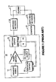
- FIG. 1 shows a typical VHF power generator 10 of the prior art.
- a rf frequency source 12 supplies power to an amplifier 14 which is fed to a directional coupler 16 .
- the directional coupler 16 is connected to diode detectors 18 and 20 .
- filters (not shown) are used between the directional coupler 16 and the detectors 18 and 20 to remove spurious frequencies.
- design of these filters is very difficult when the spurious frequencies are very close to the generator output frequency. For example, if the spurious frequency has an amplitude that is higher than the generator output and this signal is close in phase to the output frequency of the generator that is being fed back to monitor the power delivered, the peak diode detectors cannot distinguish between the true feedback signal and the signal of the spurious frequency. Therefore, the detected signals connected to the feedback power control circuitry 22 would be in error.
- a matching network 24 is connected between the generator 10 and plasma chamber 26 in a typical system application.
- a second generator 30 coupled through matching network 32 may supply power to the chamber at a different operating frequency.
- an improved RF power control method for plasma applications that optimizes the feedback control voltage in the presence of harmonic and non-harmonic spurious caused by interaction between multiple generators acting on the non-linear plasma.
- an oscillator and mixer are placed at the sampled output of the solid state RF source used for plasma ignition. The sampled output is mixed to an intermediate frequency and filtered to remove the spurious frequencies that are created in the non-linear plasma. In this way, the feedback power control essentially ignores the spurious frequencies.
- the oscillator and mixer do not interfere with other desirable system characteristics and effectively isolate the feedback control voltage from changes in plasma spurious frequency content. This allows RF power to be delivered to the plasma with greater accuracy than would otherwise be possible with conventional power control methods
- FIG. 1 illustrates a block diagram of a prior art VHF power generator
- FIG. 2 illustrates a block diagram of a VHF power generator a with generalized heterodyne detector function incorporating the principles of this invention
- FIG. 3 illustrates a block diagram of a VHF power generator with a heterodyne detector function utilizing a rms detector
- FIG. 4 illustrates a block diagram of a VHF power generator with a variable frequency heterodyne detector.
- FIG. 2 There is shown in FIG. 2 a VHF generator 10 ′ that incorporates the principles of this invention that detects and monitors the power delivered to plasma in a plasma processing system such as that shown FIG. 1 .
- a 162 MHz rf source 12 is connected to the power amplifier 14 and sends power to the directional coupler 16 .
- Sampled 162 MHz forward and reflected signals are taken from the directional coupler 16 and injected into the detector circuit where these signals are mixed with a base frequency.
- the detector circuit is comprised of band pass filters 20 ′, 22 ′, mixers 24 ′, 26 ′; and a heterodyne oscillator 28 .
- the mixed frequencies are passed through low pass filters 30 ′ and 32 ′ there they are amplified by amplifiers 34 and 36 and detected by detectors 38 and 40 .
- the detected signals are then fed back to a generator control circuit 42 .
- This heterodyne detection circuit allows the output of the generator at 18 to be constantly adjusted for changing plasma conditions.
- the detector circuit is capable of taking several options for the oscillator frequency, with appropriate change in filtering.
- the forward power signal has frequency components as follows,
- f 0 fundamental frequency (In our case this is 162 MHz).
- f 1 Second frequency (2 MHz in this case).
- the forward power signal may contain frequency components of 162 MHz, 324 MHz, 486 MHz, 648 MHz, 810 MHz, . . . etc.
- the mixed frequencies are at 200 kHz, 161.8 MHz, 164 MHz, 323.8 MHz, etc.
- This spectrum is then filtered through the low pass filters 30 ′, 32 ′ that only allows the 200 KHz signal to pass through.
- the low pass filters 30 ′, 32 ′ that only allows the 200 KHz signal to pass through.
- the power detector may be designed for either fixed frequency or variable frequency generator operation.
- FIG. 2 shows the heterodyne detector connected between the directional coupler in place of the conventional diode detector.
- the power control circuitry within the generator is effectively isolated by the heterodyne detector from changes in the spurious content of the waveform at the output of the generator and always senses only the generator output power. This results in improved plasma stability and more consistent process results.
- the power control is optimized for operation at the output frequency without compromises needed to maintain power control accuracy in the presence of spurious. It is understood that the mixers and filters shown may be of the active or passive type and the filters may use either lumped element or distributed components.
- the directional coupler forward and reflected power samples are band pass filtered to remove harmonics and low frequency spurious ahead of the mixers. It is understood that the output of the 162.2 MHz oscillator is filtered to reduce its harmonics.
- the outputs of the mixers are passed through 200 kHz filters. Other oscillator frequencies may be used to produce filter frequencies other than 200 kHz as long as the unwanted spurious frequencies appear outside the filter band pass.
- the filter output is amplified, detected, and used in the normal way for feedback power control of the generator.
- FIG. 3 illustrates another embodiment that utilizes true RMS detectors 44 and 46 in place of the diode detectors.
- the block diagram of FIG. 3 shows such detectors operating directly on the 200 kHz waveform.
- Still another embodiment derives the oscillator frequency from the generator variable frequency source, thus allowing the heterodyne detector to track the variable output frequency of the generator.
- the block diagram of this embodiment is shown in FIG. 4.
- a 57-63 MHz MHz application is shown.
- the output of the variable frequency source 48 is mixed with an 80 MHz signal to give 137-143 MHz. This is filtered and mixed with 79.8 MHz down to 57.2-63.2 MHz.
- This signal is then mixed with the original 57-63 MHz to provide the necessary 200 kHz for the low pass filter and the detector circuit. It is understood that suitable amplification may be used along the signal path to compensate for losses that occur during the frequency conversion process.
- variable frequency injected into Mixer # 1 may be derived by other means, such as an additional output of the generator variable frequency source.
Abstract
Description
Claims (8)
Priority Applications (4)
| Application Number | Priority Date | Filing Date | Title |
|---|---|---|---|
| US10/620,129 US6791274B1 (en) | 2003-07-15 | 2003-07-15 | RF power control device for RF plasma applications |
| JP2006520335A JP4807850B2 (en) | 2003-07-15 | 2004-07-14 | Improved RF power control device for RF plasma application |
| PCT/US2004/022761 WO2005010913A2 (en) | 2003-07-15 | 2004-07-14 | An improved rf power control device for rf plasma applications |
| US11/519,242 USRE42917E1 (en) | 2003-07-15 | 2006-09-11 | RF power control device for RF plasma applications |
Applications Claiming Priority (1)
| Application Number | Priority Date | Filing Date | Title |
|---|---|---|---|
| US10/620,129 US6791274B1 (en) | 2003-07-15 | 2003-07-15 | RF power control device for RF plasma applications |
Related Child Applications (1)
| Application Number | Title | Priority Date | Filing Date |
|---|---|---|---|
| US11/519,242 Reissue USRE42917E1 (en) | 2003-07-15 | 2006-09-11 | RF power control device for RF plasma applications |
Publications (1)
| Publication Number | Publication Date |
|---|---|
| US6791274B1 true US6791274B1 (en) | 2004-09-14 |
Family
ID=32927881
Family Applications (2)
| Application Number | Title | Priority Date | Filing Date |
|---|---|---|---|
| US10/620,129 Ceased US6791274B1 (en) | 2003-07-15 | 2003-07-15 | RF power control device for RF plasma applications |
| US11/519,242 Expired - Lifetime USRE42917E1 (en) | 2003-07-15 | 2006-09-11 | RF power control device for RF plasma applications |
Family Applications After (1)
| Application Number | Title | Priority Date | Filing Date |
|---|---|---|---|
| US11/519,242 Expired - Lifetime USRE42917E1 (en) | 2003-07-15 | 2006-09-11 | RF power control device for RF plasma applications |
Country Status (3)
| Country | Link |
|---|---|
| US (2) | US6791274B1 (en) |
| JP (1) | JP4807850B2 (en) |
| WO (1) | WO2005010913A2 (en) |
Cited By (60)
| Publication number | Priority date | Publication date | Assignee | Title |
|---|---|---|---|---|
| US20040253921A1 (en) * | 2002-09-23 | 2004-12-16 | Turner Terry R. | Transducer package for process control |
| US20050212617A1 (en) * | 2004-01-02 | 2005-09-29 | Lu Chen | Directional coupler |
| US6958630B2 (en) * | 2001-10-30 | 2005-10-25 | Pearl Kogyo Co., Ltd. | High-frequency detection method and high-frequency detection circuit |
| US20050266691A1 (en) * | 2004-05-11 | 2005-12-01 | Applied Materials Inc. | Carbon-doped-Si oxide etch using H2 additive in fluorocarbon etch chemistry |
| US20070073498A1 (en) * | 2004-03-25 | 2007-03-29 | Huettinger Elektronik Gmbh + Co. Kg | Method of detecting arc discharges in a plasma process |
| US20070122069A1 (en) * | 2001-05-01 | 2007-05-31 | Cadle Terry M | Surface Densification of Powder Metal Bearing Caps |
| EP1926352A1 (en) * | 2006-11-22 | 2008-05-28 | Pearl Kogyo Co., Ltd | High frequency power supply device and high frequency power supplying method |
| US20080121625A1 (en) * | 2006-11-28 | 2008-05-29 | HUETTINGER ELEKTRONIK GMBH + CO. KG | Detecting arc discharges |
| US20080121517A1 (en) * | 2006-11-23 | 2008-05-29 | Moritz Nitschke | Method for operating a plasma process and arc discharge detection device |
| US20080257869A1 (en) * | 2006-12-14 | 2008-10-23 | Huettinger Elektronik Gmbh + Co. Kg | Responding to arc discharges |
| US20090281741A1 (en) * | 2008-05-07 | 2009-11-12 | Van Zyl Gideon J | System, method, and apparatus for monitoring power |
| US20100219757A1 (en) * | 2009-02-27 | 2010-09-02 | Souheil Benzerrouk | Method and Apparatus of Providing Power to Ignite and Sustain a Plasma in a Reactive Gas Generator |
| US20100231296A1 (en) * | 2005-10-31 | 2010-09-16 | Mks Instruments, Inc. | Radio Frequency Power Delivery System |
| US20100270141A1 (en) * | 2009-04-27 | 2010-10-28 | Advanced Energy Industries, Inc. | Detecting and Preventing Instabilities in Plasma Processes |
| US20100327749A1 (en) * | 2006-11-24 | 2010-12-30 | Huettinger Elektronik Gmbh + Co. Kg | Controlled Plasma Power Supply |
| US20100327927A1 (en) * | 2009-06-25 | 2010-12-30 | Mks Instruments, Inc. | Method and system for controlling radio frequency power |
| US20110204992A1 (en) * | 2010-02-19 | 2011-08-25 | Harris Corporation | Radio frequency directional coupler device and related methods |
| CN102518541A (en) * | 2011-12-27 | 2012-06-27 | 成都集思科技有限公司 | Solid state microwave source for ignition of internal combustion engine |
| US20120299671A1 (en) * | 2010-01-18 | 2012-11-29 | Tokyo Electron Limited | Electromagnetic-radiation power-supply mechanism and microwave introduction mechanism |
| CN103474321A (en) * | 2012-02-28 | 2013-12-25 | 株式会社新动力等离子体 | Method and apparatus for detecting arc in plasma chamber |
| US8710926B2 (en) | 2005-10-31 | 2014-04-29 | Mks Instruments, Inc. | Radio frequency power delivery system |
| CN104904323A (en) * | 2012-12-04 | 2015-09-09 | 先进能源工业公司 | Frequency tuning system and method for finding a global optimum |
| US9196459B2 (en) | 2014-01-10 | 2015-11-24 | Reno Technologies, Inc. | RF impedance matching network |
| US9276456B2 (en) | 2012-12-18 | 2016-03-01 | Trumpf Huettinger Gmbh + Co. Kg | Generating high-frequency power for a load |
| US9279722B2 (en) | 2012-04-30 | 2016-03-08 | Agilent Technologies, Inc. | Optical emission system including dichroic beam combiner |
| US9306533B1 (en) | 2015-02-20 | 2016-04-05 | Reno Technologies, Inc. | RF impedance matching network |
| US9496122B1 (en) | 2014-01-10 | 2016-11-15 | Reno Technologies, Inc. | Electronically variable capacitor and RF matching network incorporating same |
| US9525412B2 (en) | 2015-02-18 | 2016-12-20 | Reno Technologies, Inc. | Switching circuit |
| US20170062186A1 (en) * | 2015-08-27 | 2017-03-02 | Mks Instruments, Inc. | Feedback Control By RF Waveform Tailoring for Ion Energy Distribution |
| US9591739B2 (en) | 2014-05-02 | 2017-03-07 | Reno Technologies, Inc. | Multi-stage heterodyne control circuit |
| US9697991B2 (en) | 2014-01-10 | 2017-07-04 | Reno Technologies, Inc. | RF impedance matching network |
| US9729122B2 (en) | 2015-02-18 | 2017-08-08 | Reno Technologies, Inc. | Switching circuit |
| US9755641B1 (en) | 2014-01-10 | 2017-09-05 | Reno Technologies, Inc. | High speed high voltage switching circuit |
| US9844127B2 (en) | 2014-01-10 | 2017-12-12 | Reno Technologies, Inc. | High voltage switching circuit |
| US9865432B1 (en) | 2014-01-10 | 2018-01-09 | Reno Technologies, Inc. | RF impedance matching network |
| US10002749B2 (en) | 2012-12-18 | 2018-06-19 | Trumpf Huettinger Gmbh + Co. Kg | Extinguishing arcs in a plasma chamber |
| US10340879B2 (en) | 2015-02-18 | 2019-07-02 | Reno Technologies, Inc. | Switching circuit |
| US10431428B2 (en) | 2014-01-10 | 2019-10-01 | Reno Technologies, Inc. | System for providing variable capacitance |
| US10455729B2 (en) | 2014-01-10 | 2019-10-22 | Reno Technologies, Inc. | Enclosure cooling system |
| US10483090B2 (en) | 2017-07-10 | 2019-11-19 | Reno Technologies, Inc. | Restricted capacitor switching |
| US10692699B2 (en) | 2015-06-29 | 2020-06-23 | Reno Technologies, Inc. | Impedance matching with restricted capacitor switching |
| US10714314B1 (en) | 2017-07-10 | 2020-07-14 | Reno Technologies, Inc. | Impedance matching network and method |
| US10727029B2 (en) | 2017-07-10 | 2020-07-28 | Reno Technologies, Inc | Impedance matching using independent capacitance and frequency control |
| CN112447471A (en) * | 2019-09-04 | 2021-03-05 | 中微半导体设备(上海)股份有限公司 | Plasma processing system and operation method thereof |
| US10984986B2 (en) | 2015-06-29 | 2021-04-20 | Reno Technologies, Inc. | Impedance matching network and method |
| US11081316B2 (en) | 2015-06-29 | 2021-08-03 | Reno Technologies, Inc. | Impedance matching network and method |
| US11101110B2 (en) | 2017-07-10 | 2021-08-24 | Reno Technologies, Inc. | Impedance matching network and method |
| US11114280B2 (en) | 2017-07-10 | 2021-09-07 | Reno Technologies, Inc. | Impedance matching with multi-level power setpoint |
| US11150283B2 (en) | 2015-06-29 | 2021-10-19 | Reno Technologies, Inc. | Amplitude and phase detection circuit |
| US11289307B2 (en) | 2017-07-10 | 2022-03-29 | Reno Technologies, Inc. | Impedance matching network and method |
| US11315758B2 (en) | 2017-07-10 | 2022-04-26 | Reno Technologies, Inc. | Impedance matching using electronically variable capacitance and frequency considerations |
| US11335540B2 (en) | 2015-06-29 | 2022-05-17 | Reno Technologies, Inc. | Impedance matching network and method |
| US11342161B2 (en) | 2015-06-29 | 2022-05-24 | Reno Technologies, Inc. | Switching circuit with voltage bias |
| US11342160B2 (en) | 2015-06-29 | 2022-05-24 | Reno Technologies, Inc. | Filter for impedance matching |
| US11393659B2 (en) | 2017-07-10 | 2022-07-19 | Reno Technologies, Inc. | Impedance matching network and method |
| US11398370B2 (en) | 2017-07-10 | 2022-07-26 | Reno Technologies, Inc. | Semiconductor manufacturing using artificial intelligence |
| US11476091B2 (en) | 2017-07-10 | 2022-10-18 | Reno Technologies, Inc. | Impedance matching network for diagnosing plasma chamber |
| US11521831B2 (en) | 2019-05-21 | 2022-12-06 | Reno Technologies, Inc. | Impedance matching network and method with reduced memory requirements |
| US11521833B2 (en) | 2017-07-10 | 2022-12-06 | Reno Technologies, Inc. | Combined RF generator and RF solid-state matching network |
| US11631570B2 (en) | 2015-02-18 | 2023-04-18 | Reno Technologies, Inc. | Switching circuit |
Families Citing this family (8)
| Publication number | Priority date | Publication date | Assignee | Title |
|---|---|---|---|---|
| JP4932787B2 (en) * | 2008-05-30 | 2012-05-16 | 株式会社ダイヘン | High frequency power supply |
| JP5354583B2 (en) * | 2009-03-31 | 2013-11-27 | 株式会社ダイヘン | High frequency power supply device and high frequency power detection device for high frequency power supply device |
| US8314561B2 (en) * | 2010-04-02 | 2012-11-20 | Mks Instruments, Inc. | Multi-channel radio frequency generator |
| CN103427915B (en) * | 2012-05-25 | 2016-08-31 | 南京中兴软件有限责任公司 | A kind of radio-frequency apparatus standing-wave ratio detection in remove interference method and device |
| US9728378B2 (en) | 2014-05-02 | 2017-08-08 | Reno Technologies, Inc. | Method for controlling an RF generator |
| US9345122B2 (en) | 2014-05-02 | 2016-05-17 | Reno Technologies, Inc. | Method for controlling an RF generator |
| US9748076B1 (en) | 2016-04-20 | 2017-08-29 | Advanced Energy Industries, Inc. | Apparatus for frequency tuning in a RF generator |
| CN111446975A (en) * | 2020-04-01 | 2020-07-24 | 上海航天测控通信研究所 | Satellite-borne VHF frequency band transmitter |
Citations (7)
| Publication number | Priority date | Publication date | Assignee | Title |
|---|---|---|---|---|
| US5654679A (en) * | 1996-06-13 | 1997-08-05 | Rf Power Products, Inc. | Apparatus for matching a variable load impedance with an RF power generator impedance |
| US5708250A (en) * | 1996-03-29 | 1998-01-13 | Lam Resarch Corporation | Voltage controller for electrostatic chuck of vacuum plasma processors |
| US5892198A (en) * | 1996-03-29 | 1999-04-06 | Lam Research Corporation | Method of and apparatus for electronically controlling r.f. energy supplied to a vacuum plasma processor and memory for same |
| US5939886A (en) * | 1994-10-24 | 1999-08-17 | Advanced Energy Industries, Inc. | Plasma monitoring and control method and system |
| US6020794A (en) * | 1998-02-09 | 2000-02-01 | Eni Technologies, Inc. | Ratiometric autotuning algorithm for RF plasma generator |
| US6472822B1 (en) * | 2000-04-28 | 2002-10-29 | Applied Materials, Inc. | Pulsed RF power delivery for plasma processing |
| US6703080B2 (en) * | 2002-05-20 | 2004-03-09 | Eni Technology, Inc. | Method and apparatus for VHF plasma processing with load mismatch reliability and stability |
Family Cites Families (11)
| Publication number | Priority date | Publication date | Assignee | Title |
|---|---|---|---|---|
| US5175472A (en) | 1991-12-30 | 1992-12-29 | Comdel, Inc. | Power monitor of RF plasma |
| US5523955A (en) * | 1992-03-19 | 1996-06-04 | Advanced Energy Industries, Inc. | System for characterizing AC properties of a processing plasma |
| US5770922A (en) * | 1996-07-22 | 1998-06-23 | Eni Technologies, Inc. | Baseband V-I probe |
| JP2001516963A (en) * | 1997-09-17 | 2001-10-02 | 東京エレクトロン株式会社 | System and method for monitoring and managing gas plasma processing |
| JP2001044873A (en) | 1999-07-29 | 2001-02-16 | Alps Electric Co Ltd | Double frequency converter |
| JP3865289B2 (en) * | 2000-11-22 | 2007-01-10 | 独立行政法人科学技術振興機構 | Microwave plasma generator |
| JP2003017296A (en) * | 2001-07-05 | 2003-01-17 | Nisshin:Kk | Plasma density information measuring method and device therefor, as well as plasma density information measuring probe, its recording medium and plasma treatment device |
| JP3778842B2 (en) * | 2001-10-30 | 2006-05-24 | パール工業株式会社 | High frequency detection method and high frequency detection circuit |
| JP4131793B2 (en) * | 2001-12-10 | 2008-08-13 | 東京エレクトロン株式会社 | High frequency power supply and control method thereof, and plasma processing apparatus |
| US6608446B1 (en) * | 2002-02-25 | 2003-08-19 | Eni Technology, Inc. | Method and apparatus for radio frequency (RF) metrology |
| US6819052B2 (en) * | 2002-05-31 | 2004-11-16 | Nagano Japan Radio Co., Ltd. | Coaxial type impedance matching device and impedance detecting method for plasma generation |
-
2003
- 2003-07-15 US US10/620,129 patent/US6791274B1/en not_active Ceased
-
2004
- 2004-07-14 WO PCT/US2004/022761 patent/WO2005010913A2/en active Application Filing
- 2004-07-14 JP JP2006520335A patent/JP4807850B2/en not_active Expired - Fee Related
-
2006
- 2006-09-11 US US11/519,242 patent/USRE42917E1/en not_active Expired - Lifetime
Patent Citations (7)
| Publication number | Priority date | Publication date | Assignee | Title |
|---|---|---|---|---|
| US5939886A (en) * | 1994-10-24 | 1999-08-17 | Advanced Energy Industries, Inc. | Plasma monitoring and control method and system |
| US5708250A (en) * | 1996-03-29 | 1998-01-13 | Lam Resarch Corporation | Voltage controller for electrostatic chuck of vacuum plasma processors |
| US5892198A (en) * | 1996-03-29 | 1999-04-06 | Lam Research Corporation | Method of and apparatus for electronically controlling r.f. energy supplied to a vacuum plasma processor and memory for same |
| US5654679A (en) * | 1996-06-13 | 1997-08-05 | Rf Power Products, Inc. | Apparatus for matching a variable load impedance with an RF power generator impedance |
| US6020794A (en) * | 1998-02-09 | 2000-02-01 | Eni Technologies, Inc. | Ratiometric autotuning algorithm for RF plasma generator |
| US6472822B1 (en) * | 2000-04-28 | 2002-10-29 | Applied Materials, Inc. | Pulsed RF power delivery for plasma processing |
| US6703080B2 (en) * | 2002-05-20 | 2004-03-09 | Eni Technology, Inc. | Method and apparatus for VHF plasma processing with load mismatch reliability and stability |
Cited By (105)
| Publication number | Priority date | Publication date | Assignee | Title |
|---|---|---|---|---|
| US20070122069A1 (en) * | 2001-05-01 | 2007-05-31 | Cadle Terry M | Surface Densification of Powder Metal Bearing Caps |
| US6958630B2 (en) * | 2001-10-30 | 2005-10-25 | Pearl Kogyo Co., Ltd. | High-frequency detection method and high-frequency detection circuit |
| US7345428B2 (en) * | 2002-09-23 | 2008-03-18 | Turner Terry R | Transducer package for process control |
| US20040253921A1 (en) * | 2002-09-23 | 2004-12-16 | Turner Terry R. | Transducer package for process control |
| US20050212617A1 (en) * | 2004-01-02 | 2005-09-29 | Lu Chen | Directional coupler |
| US7218186B2 (en) * | 2004-01-02 | 2007-05-15 | Scientific Components Corporation | Directional coupler |
| US8007641B2 (en) | 2004-03-25 | 2011-08-30 | Huettinger Elektronik Gmbh + Co. Kg | Method of detecting arc discharges in a plasma process |
| US9484189B2 (en) | 2004-03-25 | 2016-11-01 | Trumpf Huettinger Gmbh + Co. Kg | Method of detecting arc discharge in a plasma process |
| US20070073498A1 (en) * | 2004-03-25 | 2007-03-29 | Huettinger Elektronik Gmbh + Co. Kg | Method of detecting arc discharges in a plasma process |
| US20050266691A1 (en) * | 2004-05-11 | 2005-12-01 | Applied Materials Inc. | Carbon-doped-Si oxide etch using H2 additive in fluorocarbon etch chemistry |
| US8710926B2 (en) | 2005-10-31 | 2014-04-29 | Mks Instruments, Inc. | Radio frequency power delivery system |
| US8633782B2 (en) * | 2005-10-31 | 2014-01-21 | Mks Instruments, Inc. | Radio frequency power delivery system |
| US20100231296A1 (en) * | 2005-10-31 | 2010-09-16 | Mks Instruments, Inc. | Radio Frequency Power Delivery System |
| EP1926352A1 (en) * | 2006-11-22 | 2008-05-28 | Pearl Kogyo Co., Ltd | High frequency power supply device and high frequency power supplying method |
| US20080128087A1 (en) * | 2006-11-22 | 2008-06-05 | Eiich Hayano | High frequency power supply device and high frequency power supplying method |
| JP2008130398A (en) * | 2006-11-22 | 2008-06-05 | Pearl Kogyo Co Ltd | High frequency power supply device and high frequency power supplying method |
| CN101188901B (en) * | 2006-11-22 | 2012-05-23 | 巴尔工业株式会社 | High frequency power supply device and high frequency power supplying method |
| US10201069B2 (en) | 2006-11-22 | 2019-02-05 | Pearl Kogyo Co., Ltd. | High frequency power supply device and high frequency power supplying method |
| US7995313B2 (en) | 2006-11-23 | 2011-08-09 | Huettinger Elektronik Gmbh + Co. Kg | Method for operating a plasma process and arc discharge detection device |
| US20080121517A1 (en) * | 2006-11-23 | 2008-05-29 | Moritz Nitschke | Method for operating a plasma process and arc discharge detection device |
| US20090289034A1 (en) * | 2006-11-23 | 2009-11-26 | Huettinger Elektronik Gmbh + Co. Kg | Operating a Plasma Process |
| US8044595B2 (en) | 2006-11-23 | 2011-10-25 | Huettinger Elektronik Gmbh + Co. Kg | Operating a plasma process |
| US20100327749A1 (en) * | 2006-11-24 | 2010-12-30 | Huettinger Elektronik Gmbh + Co. Kg | Controlled Plasma Power Supply |
| US8110992B2 (en) * | 2006-11-24 | 2012-02-07 | Huettinger Elektronik Gmbh + Co. Kg | Controlled plasma power supply |
| US20080121625A1 (en) * | 2006-11-28 | 2008-05-29 | HUETTINGER ELEKTRONIK GMBH + CO. KG | Detecting arc discharges |
| US8085054B2 (en) | 2006-11-28 | 2011-12-27 | Huettinger Elektronik Gmbh + Co. Kg | Detecting arc discharges |
| US8735767B2 (en) | 2006-12-14 | 2014-05-27 | Trumpf Huettinger Gmbh + Co. Kg | Responding to arc discharges |
| US20080257869A1 (en) * | 2006-12-14 | 2008-10-23 | Huettinger Elektronik Gmbh + Co. Kg | Responding to arc discharges |
| US20090281741A1 (en) * | 2008-05-07 | 2009-11-12 | Van Zyl Gideon J | System, method, and apparatus for monitoring power |
| US7970562B2 (en) | 2008-05-07 | 2011-06-28 | Advanced Energy Industries, Inc. | System, method, and apparatus for monitoring power |
| US20100219757A1 (en) * | 2009-02-27 | 2010-09-02 | Souheil Benzerrouk | Method and Apparatus of Providing Power to Ignite and Sustain a Plasma in a Reactive Gas Generator |
| US8692466B2 (en) * | 2009-02-27 | 2014-04-08 | Mks Instruments Inc. | Method and apparatus of providing power to ignite and sustain a plasma in a reactive gas generator |
| US20100270141A1 (en) * | 2009-04-27 | 2010-10-28 | Advanced Energy Industries, Inc. | Detecting and Preventing Instabilities in Plasma Processes |
| US8674606B2 (en) * | 2009-04-27 | 2014-03-18 | Advanced Energy Industries, Inc. | Detecting and preventing instabilities in plasma processes |
| US8912835B2 (en) | 2009-06-25 | 2014-12-16 | Mks Instruments Inc. | Method and system for controlling radio frequency power |
| US20100327927A1 (en) * | 2009-06-25 | 2010-12-30 | Mks Instruments, Inc. | Method and system for controlling radio frequency power |
| US8659335B2 (en) * | 2009-06-25 | 2014-02-25 | Mks Instruments, Inc. | Method and system for controlling radio frequency power |
| US20120299671A1 (en) * | 2010-01-18 | 2012-11-29 | Tokyo Electron Limited | Electromagnetic-radiation power-supply mechanism and microwave introduction mechanism |
| US9072158B2 (en) * | 2010-01-18 | 2015-06-30 | Tokyo Electron Limited | Electromagnetic-radiation power-supply mechanism for exciting a coaxial waveguide by using first and second poles and a ring-shaped reflection portion |
| US20110204992A1 (en) * | 2010-02-19 | 2011-08-25 | Harris Corporation | Radio frequency directional coupler device and related methods |
| EP2362483A1 (en) * | 2010-02-19 | 2011-08-31 | Harris Corporation | Radio frequency directional coupler device and related methods |
| US8169277B2 (en) | 2010-02-19 | 2012-05-01 | Harris Corporation | Radio frequency directional coupler device and related methods |
| CN102518541A (en) * | 2011-12-27 | 2012-06-27 | 成都集思科技有限公司 | Solid state microwave source for ignition of internal combustion engine |
| CN102518541B (en) * | 2011-12-27 | 2015-05-20 | 成都集思科技有限公司 | Solid state microwave source for ignition of internal combustion engine |
| TWI505319B (en) * | 2012-02-28 | 2015-10-21 | New Power Plasma Co Ltd | Method and apparatus for detecting arc in plasma chamber |
| CN103474321A (en) * | 2012-02-28 | 2013-12-25 | 株式会社新动力等离子体 | Method and apparatus for detecting arc in plasma chamber |
| US10401221B2 (en) | 2012-04-30 | 2019-09-03 | Agilent Technologies, Inc. | Optical emission system including dichroic beam combiner |
| US9752933B2 (en) | 2012-04-30 | 2017-09-05 | Agilent Technologies, Inc. | Optical emission system including dichroic beam combiner |
| US9279722B2 (en) | 2012-04-30 | 2016-03-08 | Agilent Technologies, Inc. | Optical emission system including dichroic beam combiner |
| EP2929760A4 (en) * | 2012-12-04 | 2016-09-07 | Advanced Energy Ind Inc | Frequency tuning system and method for finding a global optimum |
| US9773644B2 (en) | 2012-12-04 | 2017-09-26 | Advanced Energy Industries, Inc. | Power generator with frequency tuning for use with plasma loads |
| CN104904323A (en) * | 2012-12-04 | 2015-09-09 | 先进能源工业公司 | Frequency tuning system and method for finding a global optimum |
| US10312064B2 (en) | 2012-12-18 | 2019-06-04 | Trumpf Huettinger Gmbh + Co. Kg | Extinguishing arcs in a plasma chamber |
| US9276456B2 (en) | 2012-12-18 | 2016-03-01 | Trumpf Huettinger Gmbh + Co. Kg | Generating high-frequency power for a load |
| US10002749B2 (en) | 2012-12-18 | 2018-06-19 | Trumpf Huettinger Gmbh + Co. Kg | Extinguishing arcs in a plasma chamber |
| US9755641B1 (en) | 2014-01-10 | 2017-09-05 | Reno Technologies, Inc. | High speed high voltage switching circuit |
| US9865432B1 (en) | 2014-01-10 | 2018-01-09 | Reno Technologies, Inc. | RF impedance matching network |
| US10460912B2 (en) | 2014-01-10 | 2019-10-29 | Reno Technologies, Inc. | RF impedance matching circuit and systems and methods incorporating same |
| US11195698B2 (en) | 2014-01-10 | 2021-12-07 | Reno Technologies, Inc. | RF impedance matching circuit and systems and methods incorporating same |
| US9196459B2 (en) | 2014-01-10 | 2015-11-24 | Reno Technologies, Inc. | RF impedance matching network |
| US10431428B2 (en) | 2014-01-10 | 2019-10-01 | Reno Technologies, Inc. | System for providing variable capacitance |
| US9844127B2 (en) | 2014-01-10 | 2017-12-12 | Reno Technologies, Inc. | High voltage switching circuit |
| US9697991B2 (en) | 2014-01-10 | 2017-07-04 | Reno Technologies, Inc. | RF impedance matching network |
| US10707057B2 (en) | 2014-01-10 | 2020-07-07 | Reno Technologies, Inc. | RF impedance matching circuit and systems and methods incorporating same |
| US10026594B2 (en) | 2014-01-10 | 2018-07-17 | Reno Technologies, Inc. | RF impedance matching network |
| US11189466B2 (en) | 2014-01-10 | 2021-11-30 | Reno Technologies, Inc. | High voltage switching circuit |
| US10455729B2 (en) | 2014-01-10 | 2019-10-22 | Reno Technologies, Inc. | Enclosure cooling system |
| US9496122B1 (en) | 2014-01-10 | 2016-11-15 | Reno Technologies, Inc. | Electronically variable capacitor and RF matching network incorporating same |
| US9591739B2 (en) | 2014-05-02 | 2017-03-07 | Reno Technologies, Inc. | Multi-stage heterodyne control circuit |
| US9525412B2 (en) | 2015-02-18 | 2016-12-20 | Reno Technologies, Inc. | Switching circuit |
| US11631570B2 (en) | 2015-02-18 | 2023-04-18 | Reno Technologies, Inc. | Switching circuit |
| US10340879B2 (en) | 2015-02-18 | 2019-07-02 | Reno Technologies, Inc. | Switching circuit |
| US10217608B2 (en) | 2015-02-18 | 2019-02-26 | Reno Technologies, Inc. | Switching circuit for RF currents |
| US9729122B2 (en) | 2015-02-18 | 2017-08-08 | Reno Technologies, Inc. | Switching circuit |
| US9306533B1 (en) | 2015-02-20 | 2016-04-05 | Reno Technologies, Inc. | RF impedance matching network |
| US9584090B2 (en) | 2015-02-20 | 2017-02-28 | Reno Technologies, Inc. | RF impedance matching network |
| US10692699B2 (en) | 2015-06-29 | 2020-06-23 | Reno Technologies, Inc. | Impedance matching with restricted capacitor switching |
| US11342160B2 (en) | 2015-06-29 | 2022-05-24 | Reno Technologies, Inc. | Filter for impedance matching |
| US11342161B2 (en) | 2015-06-29 | 2022-05-24 | Reno Technologies, Inc. | Switching circuit with voltage bias |
| US11335540B2 (en) | 2015-06-29 | 2022-05-17 | Reno Technologies, Inc. | Impedance matching network and method |
| US11150283B2 (en) | 2015-06-29 | 2021-10-19 | Reno Technologies, Inc. | Amplitude and phase detection circuit |
| US10984986B2 (en) | 2015-06-29 | 2021-04-20 | Reno Technologies, Inc. | Impedance matching network and method |
| US11081316B2 (en) | 2015-06-29 | 2021-08-03 | Reno Technologies, Inc. | Impedance matching network and method |
| US10692698B2 (en) | 2015-08-27 | 2020-06-23 | Mks Instruments, Inc. | Feedback control by RF waveform tailoring for ion energy distribution |
| US20170062186A1 (en) * | 2015-08-27 | 2017-03-02 | Mks Instruments, Inc. | Feedback Control By RF Waveform Tailoring for Ion Energy Distribution |
| US10395895B2 (en) * | 2015-08-27 | 2019-08-27 | Mks Instruments, Inc. | Feedback control by RF waveform tailoring for ion energy distribution |
| US10714314B1 (en) | 2017-07-10 | 2020-07-14 | Reno Technologies, Inc. | Impedance matching network and method |
| US10720309B1 (en) | 2017-07-10 | 2020-07-21 | Reno Technologies, Inc. | Impedance matching network and method |
| US11101110B2 (en) | 2017-07-10 | 2021-08-24 | Reno Technologies, Inc. | Impedance matching network and method |
| US11948775B2 (en) | 2017-07-10 | 2024-04-02 | Asm America, Inc. | Combined RF generator and RF solid-state matching network |
| US11264210B2 (en) | 2017-07-10 | 2022-03-01 | Reno Technologies, Inc. | Impedance matching network and method |
| US11289307B2 (en) | 2017-07-10 | 2022-03-29 | Reno Technologies, Inc. | Impedance matching network and method |
| US11315758B2 (en) | 2017-07-10 | 2022-04-26 | Reno Technologies, Inc. | Impedance matching using electronically variable capacitance and frequency considerations |
| US10741364B1 (en) | 2017-07-10 | 2020-08-11 | Reno Technologies, Inc. | Impedance matching network and method |
| US10727029B2 (en) | 2017-07-10 | 2020-07-28 | Reno Technologies, Inc | Impedance matching using independent capacitance and frequency control |
| US11114280B2 (en) | 2017-07-10 | 2021-09-07 | Reno Technologies, Inc. | Impedance matching with multi-level power setpoint |
| US11393659B2 (en) | 2017-07-10 | 2022-07-19 | Reno Technologies, Inc. | Impedance matching network and method |
| US11398370B2 (en) | 2017-07-10 | 2022-07-26 | Reno Technologies, Inc. | Semiconductor manufacturing using artificial intelligence |
| US11476091B2 (en) | 2017-07-10 | 2022-10-18 | Reno Technologies, Inc. | Impedance matching network for diagnosing plasma chamber |
| US10483090B2 (en) | 2017-07-10 | 2019-11-19 | Reno Technologies, Inc. | Restricted capacitor switching |
| US11521833B2 (en) | 2017-07-10 | 2022-12-06 | Reno Technologies, Inc. | Combined RF generator and RF solid-state matching network |
| US11557461B2 (en) | 2017-07-10 | 2023-01-17 | Reno Technologies, Inc. | Impedance matching network |
| US11538662B2 (en) | 2019-05-21 | 2022-12-27 | Reno Technologies, Inc. | Impedance matching network and method with reduced memory requirements |
| US11521831B2 (en) | 2019-05-21 | 2022-12-06 | Reno Technologies, Inc. | Impedance matching network and method with reduced memory requirements |
| CN112447471A (en) * | 2019-09-04 | 2021-03-05 | 中微半导体设备(上海)股份有限公司 | Plasma processing system and operation method thereof |
Also Published As
| Publication number | Publication date |
|---|---|
| WO2005010913A3 (en) | 2005-03-31 |
| WO2005010913A2 (en) | 2005-02-03 |
| JP2007532028A (en) | 2007-11-08 |
| USRE42917E1 (en) | 2011-11-15 |
| JP4807850B2 (en) | 2011-11-02 |
Similar Documents
| Publication | Publication Date | Title |
|---|---|---|
| US6791274B1 (en) | RF power control device for RF plasma applications | |
| KR100382772B1 (en) | Feedforward amplification system having mask detection compensation | |
| US6650181B2 (en) | High-frequency amplifier | |
| US4926134A (en) | Gain monitoring of distortion cancellation amplifiers in a feedforward linear amplifier | |
| EP1113574A3 (en) | Feed-foward amplifier and controller of the same | |
| MY108184A (en) | Feed forward amplifier network with frequency swept pilot tone. | |
| CN103134983A (en) | Terahertz coherent detection system based on single mixer and method | |
| JP4719383B2 (en) | Local oscillator and method of using the same | |
| US4466128A (en) | Automatically centered pulsed FM receiver | |
| US6087898A (en) | Closed loop feed forward system featuring carrier reutilization for synchronous detection | |
| US6501259B1 (en) | Analog phase frequency detecting apparatus and method | |
| KR102161155B1 (en) | Rf power monitoring apparatus of plasma generator | |
| KR102161156B1 (en) | Rf power monitoring apparatus of plasma generator and its method | |
| US5285120A (en) | Broadband phase splitter | |
| JP2001274495A (en) | Autolock method for laser beam oscillation frequency | |
| Walls | Practical problems involving phase noise measurements | |
| US4605908A (en) | Disable circuit for a phase locked loop discriminator circuit | |
| US20030104783A1 (en) | Adaptive electromagnetic interference rejection system and method | |
| RU2669065C1 (en) | Device for protecting automated systems from information disclosure on channels of side electromagnetic radiation | |
| Hayward et al. | High-sensitivity transient spectroscopy using tunable diode lasers | |
| RU2792686C1 (en) | Spectroanalyzer | |
| KR101046990B1 (en) | Fine signal detector | |
| Martin et al. | A Schottky receiver for nonperturbative tune monitoring in the Tevatron | |
| WO1981001921A1 (en) | Radio frequency detector | |
| KR950000104Y1 (en) | Carrier detection system |
Legal Events
| Date | Code | Title | Description |
|---|---|---|---|
| AS | Assignment |
Owner name: ADVANCED ENERGY INDUSTRIES, INC., COLORADO Free format text: ASSIGNMENT OF ASSIGNORS INTEREST;ASSIGNORS:HAUER, FREDERICK;BHUTTA,IMRAN;DECKER, RONALD A.;AND OTHERS;REEL/FRAME:014292/0190 Effective date: 20030613 |
|
| STCF | Information on status: patent grant |
Free format text: PATENTED CASE |
|
| RF | Reissue application filed |
Effective date: 20060911 |
|
| FPAY | Fee payment |
Year of fee payment: 4 |
|
| AS | Assignment |
Owner name: AES GLOBAL HOLDINGS, PTE. LTD., SINGAPORE Free format text: ASSIGNMENT OF ASSIGNORS INTEREST;ASSIGNOR:ADVANCED ENERGY INDUSTRIES, INC.;REEL/FRAME:043956/0974 Effective date: 20170913 |