EP1933075A1 - Pulsationsdämpfer, Verfahren zur Herstellung und Verwendung der Pulsationsdämpfer - Google Patents
Pulsationsdämpfer, Verfahren zur Herstellung und Verwendung der Pulsationsdämpfer Download PDFInfo
- Publication number
- EP1933075A1 EP1933075A1 EP08004238A EP08004238A EP1933075A1 EP 1933075 A1 EP1933075 A1 EP 1933075A1 EP 08004238 A EP08004238 A EP 08004238A EP 08004238 A EP08004238 A EP 08004238A EP 1933075 A1 EP1933075 A1 EP 1933075A1
- Authority
- EP
- European Patent Office
- Prior art keywords
- pulsation damper
- compensation chamber
- damper according
- piston
- chamber
- Prior art date
- Legal status (The legal status is an assumption and is not a legal conclusion. Google has not performed a legal analysis and makes no representation as to the accuracy of the status listed.)
- Granted
Links
- 230000010349 pulsation Effects 0.000 title claims abstract description 92
- 238000004519 manufacturing process Methods 0.000 title claims abstract description 13
- 238000000034 method Methods 0.000 title claims abstract description 8
- 239000012528 membrane Substances 0.000 claims abstract description 18
- 229910000831 Steel Inorganic materials 0.000 claims abstract 2
- XAGFODPZIPBFFR-UHFFFAOYSA-N aluminium Chemical compound [Al] XAGFODPZIPBFFR-UHFFFAOYSA-N 0.000 claims abstract 2
- 229910052782 aluminium Inorganic materials 0.000 claims abstract 2
- 239000010959 steel Substances 0.000 claims abstract 2
- 238000007789 sealing Methods 0.000 claims description 21
- 238000002347 injection Methods 0.000 claims description 10
- 239000007924 injection Substances 0.000 claims description 10
- IJGRMHOSHXDMSA-UHFFFAOYSA-N Atomic nitrogen Chemical compound N#N IJGRMHOSHXDMSA-UHFFFAOYSA-N 0.000 claims description 8
- 229910052757 nitrogen Inorganic materials 0.000 claims description 4
- 238000005520 cutting process Methods 0.000 claims description 3
- 239000011324 bead Substances 0.000 claims 1
- 239000012530 fluid Substances 0.000 description 17
- 238000010276 construction Methods 0.000 description 3
- 238000009499 grossing Methods 0.000 description 3
- 238000011161 development Methods 0.000 description 2
- 230000018109 developmental process Effects 0.000 description 2
- 238000012423 maintenance Methods 0.000 description 2
- 239000000463 material Substances 0.000 description 2
- 239000000126 substance Substances 0.000 description 2
- 206010000369 Accident Diseases 0.000 description 1
- 229920002943 EPDM rubber Polymers 0.000 description 1
- 230000009172 bursting Effects 0.000 description 1
- 230000003749 cleanliness Effects 0.000 description 1
- 238000001816 cooling Methods 0.000 description 1
- 238000013016 damping Methods 0.000 description 1
- 230000000694 effects Effects 0.000 description 1
- 238000010438 heat treatment Methods 0.000 description 1
- 239000011261 inert gas Substances 0.000 description 1
- 230000004054 inflammatory process Effects 0.000 description 1
- 238000009434 installation Methods 0.000 description 1
- 230000010354 integration Effects 0.000 description 1
- 230000002093 peripheral effect Effects 0.000 description 1
- 238000005096 rolling process Methods 0.000 description 1
- 239000006228 supernatant Substances 0.000 description 1
- 238000011144 upstream manufacturing Methods 0.000 description 1
Images


Classifications
-
- F—MECHANICAL ENGINEERING; LIGHTING; HEATING; WEAPONS; BLASTING
- F16—ENGINEERING ELEMENTS AND UNITS; GENERAL MEASURES FOR PRODUCING AND MAINTAINING EFFECTIVE FUNCTIONING OF MACHINES OR INSTALLATIONS; THERMAL INSULATION IN GENERAL
- F16L—PIPES; JOINTS OR FITTINGS FOR PIPES; SUPPORTS FOR PIPES, CABLES OR PROTECTIVE TUBING; MEANS FOR THERMAL INSULATION IN GENERAL
- F16L55/00—Devices or appurtenances for use in, or in connection with, pipes or pipe systems
- F16L55/04—Devices damping pulsations or vibrations in fluids
- F16L55/045—Devices damping pulsations or vibrations in fluids specially adapted to prevent or minimise the effects of water hammer
- F16L55/05—Buffers therefor
- F16L55/052—Pneumatic reservoirs
- F16L55/053—Pneumatic reservoirs the gas in the reservoir being separated from the fluid in the pipe
- F16L55/054—Pneumatic reservoirs the gas in the reservoir being separated from the fluid in the pipe the reservoir being placed in or around the pipe from which it is separated by a sleeve-shaped membrane
-
- F—MECHANICAL ENGINEERING; LIGHTING; HEATING; WEAPONS; BLASTING
- F15—FLUID-PRESSURE ACTUATORS; HYDRAULICS OR PNEUMATICS IN GENERAL
- F15B—SYSTEMS ACTING BY MEANS OF FLUIDS IN GENERAL; FLUID-PRESSURE ACTUATORS, e.g. SERVOMOTORS; DETAILS OF FLUID-PRESSURE SYSTEMS, NOT OTHERWISE PROVIDED FOR
- F15B21/00—Common features of fluid actuator systems; Fluid-pressure actuator systems or details thereof, not covered by any other group of this subclass
- F15B21/008—Reduction of noise or vibration
-
- F—MECHANICAL ENGINEERING; LIGHTING; HEATING; WEAPONS; BLASTING
- F16—ENGINEERING ELEMENTS AND UNITS; GENERAL MEASURES FOR PRODUCING AND MAINTAINING EFFECTIVE FUNCTIONING OF MACHINES OR INSTALLATIONS; THERMAL INSULATION IN GENERAL
- F16L—PIPES; JOINTS OR FITTINGS FOR PIPES; SUPPORTS FOR PIPES, CABLES OR PROTECTIVE TUBING; MEANS FOR THERMAL INSULATION IN GENERAL
- F16L55/00—Devices or appurtenances for use in, or in connection with, pipes or pipe systems
- F16L55/04—Devices damping pulsations or vibrations in fluids
- F16L55/045—Devices damping pulsations or vibrations in fluids specially adapted to prevent or minimise the effects of water hammer
- F16L55/05—Buffers therefor
- F16L55/052—Pneumatic reservoirs
- F16L55/053—Pneumatic reservoirs the gas in the reservoir being separated from the fluid in the pipe
-
- F—MECHANICAL ENGINEERING; LIGHTING; HEATING; WEAPONS; BLASTING
- F15—FLUID-PRESSURE ACTUATORS; HYDRAULICS OR PNEUMATICS IN GENERAL
- F15B—SYSTEMS ACTING BY MEANS OF FLUIDS IN GENERAL; FLUID-PRESSURE ACTUATORS, e.g. SERVOMOTORS; DETAILS OF FLUID-PRESSURE SYSTEMS, NOT OTHERWISE PROVIDED FOR
- F15B2201/00—Accumulators
- F15B2201/20—Accumulator cushioning means
- F15B2201/205—Accumulator cushioning means using gas
-
- F—MECHANICAL ENGINEERING; LIGHTING; HEATING; WEAPONS; BLASTING
- F15—FLUID-PRESSURE ACTUATORS; HYDRAULICS OR PNEUMATICS IN GENERAL
- F15B—SYSTEMS ACTING BY MEANS OF FLUIDS IN GENERAL; FLUID-PRESSURE ACTUATORS, e.g. SERVOMOTORS; DETAILS OF FLUID-PRESSURE SYSTEMS, NOT OTHERWISE PROVIDED FOR
- F15B2201/00—Accumulators
- F15B2201/20—Accumulator cushioning means
- F15B2201/21—Accumulator cushioning means using springs
-
- F—MECHANICAL ENGINEERING; LIGHTING; HEATING; WEAPONS; BLASTING
- F15—FLUID-PRESSURE ACTUATORS; HYDRAULICS OR PNEUMATICS IN GENERAL
- F15B—SYSTEMS ACTING BY MEANS OF FLUIDS IN GENERAL; FLUID-PRESSURE ACTUATORS, e.g. SERVOMOTORS; DETAILS OF FLUID-PRESSURE SYSTEMS, NOT OTHERWISE PROVIDED FOR
- F15B2201/00—Accumulators
- F15B2201/30—Accumulator separating means
- F15B2201/31—Accumulator separating means having rigid separating means, e.g. pistons
-
- F—MECHANICAL ENGINEERING; LIGHTING; HEATING; WEAPONS; BLASTING
- F15—FLUID-PRESSURE ACTUATORS; HYDRAULICS OR PNEUMATICS IN GENERAL
- F15B—SYSTEMS ACTING BY MEANS OF FLUIDS IN GENERAL; FLUID-PRESSURE ACTUATORS, e.g. SERVOMOTORS; DETAILS OF FLUID-PRESSURE SYSTEMS, NOT OTHERWISE PROVIDED FOR
- F15B2201/00—Accumulators
- F15B2201/30—Accumulator separating means
- F15B2201/315—Accumulator separating means having flexible separating means
- F15B2201/3151—Accumulator separating means having flexible separating means the flexible separating means being diaphragms or membranes
-
- F—MECHANICAL ENGINEERING; LIGHTING; HEATING; WEAPONS; BLASTING
- F15—FLUID-PRESSURE ACTUATORS; HYDRAULICS OR PNEUMATICS IN GENERAL
- F15B—SYSTEMS ACTING BY MEANS OF FLUIDS IN GENERAL; FLUID-PRESSURE ACTUATORS, e.g. SERVOMOTORS; DETAILS OF FLUID-PRESSURE SYSTEMS, NOT OTHERWISE PROVIDED FOR
- F15B2201/00—Accumulators
- F15B2201/40—Constructional details of accumulators not otherwise provided for
- F15B2201/41—Liquid ports
- F15B2201/413—Liquid ports having multiple liquid ports
Definitions
- the invention relates to a pulsation damper, comprising a base body having an inlet and an outlet, which are flow-connected to each other through a channel, wherein the channel has passageways, which connect the channel with an overflow chamber, and wherein the overflow chamber by an at least partially flexible membrane of a Compensation chamber is separated.
- the invention further relates to a pulsation damper, comprising a base body, wherein the base body comprises a compensation chamber, wherein a piston is at least partially movable within the compensation chamber and wherein the piston is acted upon on the side facing away from the compensation chamber with pressure.
- the invention also relates to a method for producing Pulsationsdämpfem, wherein at least the components of the Pulsationsdämpfers, which are needed to produce a closed balancing chamber without supply, are positioned in a working space and wherein the components are assembled for the final production of the compensation chamber.
- the invention relates to a use of pulsation dampers in hydraulic supply systems of motor vehicles.
- Pulsation dampers and methods are already known from the prior art. Pulsation dampers of the type mentioned are used in hydraulic lines. They are used in particular for smoothing or reducing pulsations in hydraulic lines.
- Piston accumulators are used in particular in chassis of motor vehicles.
- the generic pulsation damper and method for producing such pulsation damper have disadvantages in view of practical use.
- the generic type pulsation dampers is particularly disadvantageous that their Ausretekammem are often acted upon only under provision of complex device with pressure.
- they To ensure proper use of the pulsation dampers, they must be subjected to constant maintenance. During maintenance, the pressure within the compensation chamber must first be checked and then adjusted to the target pressure.
- the compensation chambers are often provided with filling nozzles, which are satisfactorily sealable against the atmosphere only in a complex manner.
- the compensation chambers no longer have the pressure, which is necessary for a perfect function of the pulsation damper after some time.
- the invention has for its object to design systems with pulsation dampers of the type mentioned in such a way and further that always optimal operation is ensured with a simple structural design.
- a pulsation damper of the type mentioned is characterized in that the Auslgeichhunt is formed as a closed space without supply line.
- a pulsation damper according to the invention has a structurally simple construction, which, after a single filling of the compensation chamber, preserves the pressure prevailing in it and ensures optimum operation.
- the sum of the volumes of the compensation chamber and the overflow chamber during operation could always be constant.
- the compensation chamber could be pressurized, it is conceivable that prevails within the compensation chamber, a pressure of 0.3 to 0.7 bar.
- the pressurization of the compensation chamber with such a pressure is advantageous in that the membrane is not damaged by expansion of the medium within the compensation chamber when the pulsation damper is heated.
- the balance chamber could be pulsed at a pressure greater than the atmospheric pressure. This makes it possible to damp pulsations with higher frequencies within a hydraulic line, since the membrane is under a relatively high voltage and thus has a high rigidity.
- the compensation chamber is filled with air.
- Air can be provided as a medium in a simple manner and can be easily spent in the balancing chamber in the form of compressed air.
- the compensation chamber could be filled with nitrogen.
- Nitrogen is characterized as an inert gas by a special chemical inertia. This chemical inertia is advantageous when the pulsation damper is used in conjunction with highly flammable fluids. Nitrogen as such is not flammable, it may also inhibit the inflammatory processes of combustible media and thus prevent fire accidents from leaking.
- a vacuum is advantageous in that it can be dispensed with a filling medium. This allows a particularly cost-effective production of a pulsation damper.
- the inlet, outlet and channel could be coaxial and colinear with each other.
- a particularly fast fluid flow through the channel can be realized.
- the pulsation damper can be used at high flow rates in hydraulic lines.
- the balance chamber and the overflow chamber could be concentric with the channel and with each other.
- This specific embodiment allows a structurally simple construction of a Pulsafionsdämpfers and a smooth fluid exchange between the channel and the overflow chamber.
- passages are provided within the channel, which extend radially into the overflow chamber. It is particularly conceivable to design the passages in a circle or as slots.
- the geometric configuration of the passages can be selected in an advantageous manner. For particularly viscous fluids, the provision of slots may be advantageous to minimize flow resistance.
- the main body could be made of three components, of which two are sealed against each other by a seal, this constructive structure minimizes the number of seals used the pulsation damper. Ultimately, only two sealing body are necessary in such a structural design. In that regard, a problem-free production with little items is feasible.
- a component at least partially accommodates two further components.
- a first component in the form of a cylindrically designed pot could be designed.
- a cylindrical member could be inserted with radially aligned passages, which is followed by another cylindrical member which partially conforms to the inner wall of the cup-shaped first component. Due to this structural design, only one interface of the components is to be sealed against the atmosphere.
- the components used could be rotationally symmetrical.
- the use of rotationally symmetrical components allows easy manufacture of the components.
- the membrane could at least partially act as a seal.
- This embodiment realizes a particularly compact and uniform construction of a pulsation damper.
- the use of the diaphragm as a seal minimizes the number of seals used within the pulsation damper.
- the membrane could be oriented concentrically to the channel. This specific arrangement of the membrane allows a large-area recording and thereby effective damping of Pulsafionen of the fluid.
- the membrane could be barrel-shaped or barrel-shaped. This embodiment is advantageous in view of a maximum surface area of the membrane which can interact with the pulsating fluid.
- the pulsation damper according to claim 16 could have a piston, which is associated with at least one guide ring for engagement with the inner wall of the compensation chamber.
- the provision of guide rings allows a backlash-free process of the piston peripheral surface on the inner wall of the compensation chamber. In that regard, a smooth sliding movement of the piston without tilting can be realized.
- the piston could be assigned at least one sealing ring for sealing engagement with the inner wall of the compensation chamber.
- the sealing ring acts as a guide.
- the number of guide rings can be minimized.
- a play-free and sealed movement of the piston within the compensation chamber can be realized by a single seal and a single further guide ring.
- the piston could be assigned a support ring. It is conceivable that the support ring rests on the sealing ring. This realizes a stable seat of the sealing ring, so that it is not subjected to tilting or twisting.
- the piston could be assigned to the application of force a spring.
- a spring allows easy adjustment of the basic stiffness of a pulsation damper by choosing a suitable Spring constant.
- coil springs, leaf springs or other elastically deformable spring elements could be used.
- the spring is arranged within the compensation chamber and abuts against the piston chamber facing the compensation chamber.
- the piston is acted upon not only by the pressure within the compensation chamber, but also by the spring force.
- This specific embodiment allows a constant rigidity of the pulsation damper at different temperatures, since any pressure changes due to heating or cooling of the medium in the compensation chamber can be compensated by the spring.
- the inner wall of the compensation chamber could be made at least partially without cutting. This specific refinement makes it possible in a sophisticated way to dispense with a complex rolling process, which is necessary in order to smooth surfaces.
- the main body could have a thread.
- the provision of a thread allows easy integration of the Pulsafionsdämpfers in an existing system of hydraulic lines. It is particularly conceivable that a thread of dimension M16 x 1.5 is used.
- the main body could be integrally formed as a deep-drawn part.
- This specific embodiment allows the production of a pulsation damper, which is composed of few parts. It is conceivable against this background that a cup-shaped basic body is formed from a workpiece, in which a piston can be inserted.
- the inner surface could have bumps smaller than 2 ⁇ m.
- Such a roughness represents a special quality, which can only be achieved by a deep drawing process. This quality of quality allows the realization of a special tightness and excellent gliding of sliding on such a surface elements.
- the main body In such an embodiment of the main body is conceivable that at least one snap ring is provided as a stop for the piston.
- the snap ring could be set on the interior of the base body in such a way that the piston can not completely slip out of the base body. This specific embodiment ensures that the compensation chamber is not connected to the atmosphere.
- the main body could have a separate lid, which limits the compensation chamber together with the piston.
- the lid associated with a seal and the lid is fixed by a flanging of the body.
- a piston can be inserted into a hollow workpiece, wherein a stop for the piston is formed within the workpiece. This stop could be formed out of the massive body in the form of a supernatant. This ensures a particularly stable system of the piston and prevents slipping out of the piston from the body.
- the main body could have a length of up to 50 mm and a maximum diameter of up to 50 mm.
- This dimensioning of the pulsation damper allows its use in an injection system or an injection system of a motor vehicle. Against this background, it is particularly conceivable that the pulsation damper is used in injection systems of motor vehicles, which are diesel or gasoline operate. By this use of the pulsation damper, a smoothing of the fluid supply of the injection system can advantageously be realized. The small design of the pulsation damper allows easy installation.
- the pulsation dampers could be functional at an operating temperature of -30 ° C to + 80 ° C and for a short time even + 90 ° C.
- the bursting pressure of the pulsation dampers could be beyond 100 bar. This makes it possible to use pulsation dampers in motor vehicles.
- the working space could be filled with the same medium, which is located in the completed compensation chamber.
- This specific embodiment allows a particularly simple manufacturing process of pulsation dampers, since in addition to the existing in the work space no additional media must be filled by complex facilities in the compensation chamber.
- the hydraulic supply system could be designed as an injection system of a motor vehicle. This use advantageously realizes a motor-friendly operation. The use advantageously ensures a smoothing of the fluid supply of the injection system.
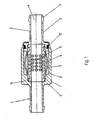
- Fig. 1 shows a pulsation damper, which can be used in hydraulic lines.
- This comprises a main body 1 with an inlet 2 and an outlet 3, which are fluidly connected to each other through a channel 4.
- the channel 4 has passages 5, which connect the channel 4 with an overflow chamber 6.
- a pressurized with pulsations fluid which flows through the channel 4, escape through the passages 5 in the overflow chamber 6.
- upstream or downstream lines pressures can be reduced in the pulsation damper.
- the overflow chamber 6 is separated from a compensation chamber 8 by a flexible membrane.
- the compensation chamber 8 is formed as a closed space without supply line.
- the sum of the volumes of the compensation chamber 8 and theParketlaufsch 6 is always constant during operation.
- the inlet 2, the outlet 3 and the channel 4 are arranged coaxially and co-linear with one another.
- the compensation chamber 8 and the overflow chamber 6 are arranged concentrically to the channel 4 and to each other
- the main body 1 consists of three components 9,10 and 11, of which two are sealed by a seal 7,12 against each other.
- the component 11 is sealed by the seal 12 against the component 9.
- the component 9 is sealed against the component 10 by the seal 7 and the component 11 is also sealed against the component 10 by the seal 7. there the membrane 7 acts as a seal.
- the component 9 accommodates two further components 10 and 11 at least partially.
- the components 9, 10 and 11 are rotationally symmetrical.
- the membrane 7 is oriented concentrically to the channel 4 and formed barrel-shaped.
- the inlet 2 and the outlet 3 have an inner diameter of 8 mm and an outer diameter of 10 mm.
- the component 10 has a length of 27 mm.
- the component 9 fixes the component 11 by a flanging.
- the material from which the component 9 is made tapers at the location of the flanging.
- the membrane is made of the material 70 EPDM 120209.
- Fig. 2 shows in a sectional drawing a pulsation damper, which can be used as a piston accumulator.
- This comprises a main body 1, wherein in the base body 1, a compensation chamber 8 is formed.
- a piston 13 is at least partially movable within the compensation chamber 8 and can be acted upon by pressure on the side facing away from the compensation chamber 8. The pressurization is effected by a fluid.
- the compensation chamber 8 is formed as a closed space without supply line.
- the piston 13 is assigned a guide ring 14 for abutment against the inner wall 15 of the compensation chamber 8.
- the piston 13 is associated with a sealing ring 16 for sealing engagement with the inner wall 15 of the compensation chamber 8.
- the sealing ring 16 acts as a guide.
- the piston 13 is associated with a support ring 17 which is adjacent to the sealing ring 16.
- the guide ring 14 and the sealing ring 16 are arranged in grooves which are formed in the piston 13.
- the inner wall 15 of the compensation chamber 8 is made without cutting, wherein the base body 1 is integrally formed as a deep-drawn part.
- the inner wall 15 of the main body 1 is associated with a snap ring 20 as a stop for the piston 13.
- Fig. 3 shows in a sectional view a pulsation damper, which can be used in injection systems of motor vehicles.
- This has a main body 1, wherein the base body 1 comprises a compensation chamber 8.
- a piston 13 is movable within the compensation chamber 8. The piston 13 is acted upon by the pressure on the side facing away from the compensation chamber 8 by a fluid.
- the compensation chamber 8 is formed as a closed space without supply line.
- the piston 13 is assigned a guide ring 14 for abutment against the inner wall 15 of the compensation chamber 8. Furthermore, the piston 13 is assigned a sealing ring 16 for sealing engagement with the inner wall of the compensation chamber 8. In this case, the sealing ring 16 acts as a guide.
- the piston 13 is assigned a spring 18 for applying force.
- the spring 18 is formed as a spiral spring.
- the spring 18 is disposed within the compensation chamber 8 and abuts against the piston chamber 8 facing the piston surface.
- the main body 1 has a separate cover 21, which limits the compensation chamber 8 together with the piston 13.
- the lid 21 is associated with a seal 22.
- the lid 21 is fixed by a flange 23 of the base body 1.
- a stop 24 is formed for the piston 13.
- the main body 1 has a length of 40 mm and a maximum diameter of 24 mm. On the main body 1, a thread 19 is formed. The thread has the dimension M16 x 1.5.
- the main body 1 can be positioned in an injection system of a motor vehicle. It serves to smooth the fluid supply and to reduce the pulsations of the fluids.
- diesel or gasoline act as fluids.
Landscapes
- Engineering & Computer Science (AREA)
- General Engineering & Computer Science (AREA)
- Mechanical Engineering (AREA)
- Chemical & Material Sciences (AREA)
- Analytical Chemistry (AREA)
- Physics & Mathematics (AREA)
- Fluid Mechanics (AREA)
- Pipe Accessories (AREA)
- Fuel-Injection Apparatus (AREA)
- Valve Device For Special Equipments (AREA)
Abstract
Description
- Die Erfindung betrifft einen Pulsationsdämpfer, umfassend einen Grundkörper mit einem Einlass und einem Auslass, die durch einen Kanal miteinander strömungsverbunden sind, wobei der Kanal Durchgänge aufweist, welche den Kanal mit einer Überlaufkammer strömungsverbinden, und wobei die Überlaufkammer durch eine zumindest teilweise flexible Membran von einer Ausgleichkammer abgetrennt ist. Die Erfindung betrifft des Weiteren einen Pulsationsdämpfer, umfassend einen Grundkörper, wobei der Grundkörper eine Ausgleichkammer umfasst, wobei ein Kolben zumindest teilweise innerhalb der Ausgleichkammer bewegbar ist und wobei der Kolben auf der der Ausgleichkammer abgewandten Seite mit Druck beaufschlagbar ist. Auch betrifft die Erfindung ein Verfahren zur Herstellung von Pulsationsdämpfem, wobei zumindest die Bauteile des Pulsationsdämpfers, welche zur Herstellung einer abgeschlossenen Ausgleichkammer ohne Zuleitung benötigt werden, in einem Arbeitsraum positioniert werden und wobei die Bauteile zur abschließenden Herstellung der Ausgleichkammer zusammengefügt werden. Schließlich betrifft die Erfindung eine Verwendung von Pulsationsdämpfern in hydraulischen Versorgungssystemen von Kraftfahrzeugen.
- Derartige Pulsationsdämpfer und Verfahren sind aus dem Stand der Technik bereits bekannt. Pulsationsdämpfer der eingangs genannten Art finden Verwendung in hydraulischen Leitungen. Sie dienen insbesondere der Glättung bzw. Reduzierung von Pulsationen in hydraulischen Leitungen.
- Des Weiteren finden die genannten Pulsationsdämpfer Verwendung als Kolbenspeicher. Kolbenspeicher werden insbesondere in Fahrwerken von Kraftfahrzeugen eingesetzt.
- Die gattungsbildenden Pulsationsdämpfer und Verfahren zur Herstellung solcher Pulsationsdämpfer weisen jedoch im Hinblick auf den praktischen Einsatz Nachteile auf. Bei den gattungsbildenden Pulsationsdämpfern ist insbesondere nachteilig, dass deren Ausgleichkammem häufig nur unter Vorkehrung komplexer Einrichtung mit Druck beaufschlagbar sind. Um einen einwandfreien Einsatz der Pulsationsdämpfer zu gewährleisten, müssen diese einer ständigen Wartung unterzogen werden. Bei der Wartung muss zunächst der Druck innerhalb der Ausgleichkammer überprüft werden und sodann dem Solldruck angepasst werden. Hierzu sind die Ausgleichkammern häufig mit Befüllstutzen versehen, die in nur aufwendiger Weise gegen die Atmosphäre zufriedenstellend abdichtbar sind.
- Aufgrund nur wenig gebrauchstauglicher Abdichtungsmaßnahmen weisen die Ausgleichkammern nach einiger Zeit nicht mehr den Druck auf, der für eine einwandfreie Funktion der Pulsationsdämpfer notwendig ist.
- Der Erfindung liegt die Aufgabe zugrunde, Systeme mit Pulsationsdämpfern der eingangs genannten Art derart auszugestalten und weiterzubilden, dass stets ein optimaler Betrieb bei einfachem konstruktivem Aufbau gewährleistet ist.
- Die vorliegende Erfindung löst die zuvor genannte Aufgabe durch die Merkmale des Patentanspruchs 1. Danach ist ein Pulsationsdämpfer der eingangs genannten Art dadurch gekennzeichnet, dass die Auslgeichkammer als abgeschlossener Raum ohne Zuleitung ausgebildet ist.
- Erfindungsgemäß ist zunächst erkannt worden, dass die gattungsbildenden Pulsationsdämpfer in konstruktiver Hinsicht wenig gebrauchstauglich ausgebildet sind. In einem nächsten Schritt ist erkannt worden, dass die bekannten Pulsationsdämpfer im Hinblick auf die Abdichtung der Ausgleichkammer erhebliche Nachteile aufweisen, Schließlich ist erkannt worden, dass eine integrale Ausbildung der Ausgleichkammer, welche als abgeschlossener Raum ausgebildet ist, nur in geringem Maße Dichtungsvorkehrungen erfordert.
- Eine aufwendige Abdichtung einer Zuleitung ist insoweit nicht notwendig. Des Weiteren werden keine Einrichtungen zur nachträglichen Befüllung der Ausgleichkammer benötigt. Insoweit weist ein erfindungsgemäßer Pulsationsdämpfer einen konstruktiv einfachen Aufbau auf, der nach einmaliger Befüllung derAusgleichkammer den in ihr vorherrschenden Druck bewahrt und einen optimalen Betrieb gewährleistet.
- Folglich ist die eingangs genannte Aufgabe gelöst.
- Im Hinblick auf eine problemlose Fertigung könnte die Summe der Volumina der Ausgleichkammer und der Überlaufkammer im Betrieb stets konstant sein, Durch diese konkrete Ausgestaltung ist es möglich, einen einzigen Hohlraum zu fertigen, welcher durch Einfügen einer einzigen Membran in zwei Räume aufteilbar ist.
- Die Ausgleichkammer könnte mit Druck beaufschlagt sein, Dabei ist denkbar, dass innerhalb der Ausgleichkammer ein Druck von 0,3 bis 0,7 bar vorherrscht. Die Beaufschlagung der Ausgleichkammer mit einem solchen Druck ist dahingehend vorteilhaft, dass die Membran bei Erwärmung des Pulsationsdämpfers durch Ausdehnung des Mediums innerhalb der Ausgleichkammer nicht beschädigt wird.
- Die Ausgleichkammer könnte mit einem Druck beauschlagt sein, der größer als der Atmosphärendruck ist. Hierdurch ist es möglich, Pulsationen mit höheren Frequenzen innerhalb einer hydraulischen Leitung zu dämpfen, da die Membran unter einer relativ hohen Spannung steht und folglich eine hohe Steifigkeit aufweist.
- Vor diesem Hintergrund ist es denkbar, dass die Ausgleichkammer mit Luft befüllt ist. Luft ist als Medium auf einfach Weise bereitstellbar und kann in Form von Pressluft problemlos in die Ausgleichkammer verbracht werden.
- Die Ausgleichkammer könnte mit Stickstoff befüllt sein. Stickstoff zeichnet sich als Inertgas durch eine besondere chemische Trägheit aus. Diese chemische Trägheit ist von Vorteil, wenn der Pulsationsdämpfer in Verbindung mit leicht entzündlichen Fluiden verwendet wird. Stickstoff ist als solcher nicht entzündlich, kann darüber hinaus Entzündungsprozesse brennbarer Medien hemmen und folglich Brandunfällen bei Undichtigkeiten vorbeugen.
- Innerhalb der Ausgleichkammer könnte ein Vakuum herrschen. Die Vorkehrung eines Vakuums ist dahingehend vorteilhaft, dass auf ein Befüllmedium verzichtet werden kann. Dies erlaubt eine besonders kostengünstige Fertigung eines Pulsationsdämpfers.
- Der Einlass, der Auslass und der Kanal könnten koaxial und kolinear zueinander angeordnet sein. Durch diese konkrete Ausgestaltung ist ein besonders schneller Fluidfiluss durch den Kanal realisierbar. Insoweit ist der Pulsationsdämpfer bei höchsten Strömungsgeschwindigkeiten in hydraulischen Leitungen einsetzbar.
- Die Ausgleichkammer und die Überlaufkammer könnten konzentrisch zum Kanal und zueinander angeordnet sein. Diese konkrete Ausgestaltung erlaubt einen konstruktiv einfachen Aufbau eines Pulsafionsdämpfers und einen problemlosen Fluidaustausch zwischen Kanal und Überlaufkammer. Vor diesem Hintergrund ist denkbar, dass innerhalb des Kanals Durchgänge vorgesehen sind, welche sich radial in die Überlaufkammer erstrecken. Dabei ist insbesondere denkbar, die Durchgänge kreisförmig oder als Schlitze auszugestalten. Je nach der Viskosität des durch den Kanal strömenden Fluids kann die geometrische Ausgestaltung der Durchgänge in vorteilhafter Weise gewählt werden. Bei besonders zähflüssigen Fluiden kann die Vorkehrung von Schlitzen vorteilhaft sein, um einen Strömungswiderstand zu minimieren.
- Der Grundkörper könnte aus drei Bauteilen gefertigt sein, von denen jeweils zwei durch eine Dichtung gegeneinander abgedichtet sind, Dieser konstruktive Aufbau minimiert die Anzahl der verwendeten Dichtungen des Pulsationsdämpfers. Letztlich sind bei einem solchen konstruktiven Aufbau nur zwei Dichtungskörper notwendig. Insoweit ist eine problemlose Fertigung mit wenig Einzelteilen realisierbar.
- Vor diesem Hintergrund ist denkbar, dass ein Bauteil zwei weitere Bauteile zumindest teilweise aufnimmt. Dabei könnte ein erstes Bauteil in Form eines zylindrisch ausgestalteten Topfes ausgestaltet sein. In dieses könnte ein zylindrisches Bauteil mit radial ausgerichteten Durchgängen einfügbar sein, an welches sich ein weiteres zylindrisches Bauteil anschließt, das sich teilweise an die Innenwandung des topfförmigen ersten Bauteils anschmiegt. Durch diese konstruktive Ausgestaltung ist nur eine Schnittstelle der Bauteile gegen die Atmosphäre abzudichten.
- Vor diesem Hintergrund könnten die verwendeten Bauteile rotationssymmetrisch ausgebildet sein. Die Verwendung rotationssymmetrischer Bauteile erlaubt eine einfache Fertigung der Bauteile.
- Die Membran könnte zumindest teilweise als Dichtung fungieren. Durch diese Ausgestaltung ist ein besonders kompakter und einheitlicher Aufbau eines Pulsationsdämpfers realisiert. Die Verwendung der Membran als Dichtung minimiert die Anzahl der verwendeten Dichtungen innerhalb.des Pulsationsdämpfers.
- Die Membran könnte konzentrisch zum Kanal orientiert sein. Diese konkrete Anordnung der Membran erlaubt eine großflächige Aufnahme und dadurch eine effektive Dämpfung der Pulsafionen des Fluids.
- Vor diesem Hintergrund könnte die Membran fassförmig oder tonnenförmig ausgebildet sein. Diese Ausgestaltung ist im Hinblick auf eine maximale Oberfläche der Membran, welche mit dem pulsierenden Fluid in Wechselwirkung treten kann, vorteilhaft.
- Des Weiteren ist die eingangs genannte Aufgabe im Hinblick auf einen Pulsationsdämpfer gemäß Patentanspruch 16 gelöst, Um Wiederholungen in Bezug auf die erfinderische Tätigkeit zu vermeiden, sei auf die Ausführungen zum Pulsationsdämpfer gemäß Patentanspruch 1 verwiesen.
- Der Pulsationsdämpfer gemäß Patentanspruch 16 könnte einen Kolben aufweisen, dem mindestens ein Führungsring zur Anlage an der Innenwandung der Ausgleichkammer zugeordnet ist. Die Vorkehrung von Führungsringen erlaubt ein spielfreies Verfahren der Kolbenumfangsfläche an der Innenwandung der Ausgleichkammer. Insoweit ist eine problemlos gleitende Bewegung des Kolbens ohne Verkippungen realisierbar.
- Dem Kolben könnte mindestens ein Dichtring zur dichtenden Anlage an der Innenwandung der Ausgleichkammer zugeordnet sein. Hierdurch ist realisiert, dass der Druck innerhalb der Ausgieichkammer konstant bleibt. Vor diesem Hintergrund ist denkbar, dass der Dichtring als Führung fungiert. Auf raffinierte Weise ist durch diese konkrete Ausgestaltung realisiert, dass die Anzahl an Führungsringen minimiert werden kann. Insoweit ist durch eine einzige Dichtung und einen einzigen weiteren Führungsring eine spielfreie und abgedichtete Bewegung des Kolbens innerhalb der Ausgleichkammer realisierbar.
- Dem Kolben könnte ein Stützring zugeordnet sein. Hierbei ist denkbar, dass der Stützring am Dichtring anliegt. Dies realisiert einen stabilen Sitz des Dichtrings, so dass dieser keinen Verkippungen oder Verdrehungen unterworfen wird.
- Dem Kolben könnte zur Kraftbeaufschlagung eine Feder zugeordnet sein. Die Vorkehrung einer Feder erlaubt eine problemlose Einstellung der Grundsteifigkeit eines Pulsationsdämpfers durch Wahl einer geeigneten Federkonstante. Dabei könnten Spiralfedern, Blattfedern oder andere elastisch deformierbare Federelemente zum Einsatz kommen.
- Vor diesem Hintergrund ist denkbar, dass die Feder innerhalb der Ausgleichkammer angeordnet ist und an der der Ausgleichkammer zugewandten Kolbenfläche anliegt. Durch diese konkrete Ausgestaltung wird der Kolben nicht nur durch den Druck innerhalb der Ausgleichkammer beaufschlagt, sondern zusätzlich durch die Federkraft. Diese konkrete Ausgestaltung erlaubt eine konstante Steifigkeit des Pulsationsdämpfers bei unterschiedlichen Temperaturen, da eventuelle Druckänderungen durch Erwärmung oder Abkühlung des Mediums in der Ausgleichkammer durch die Feder kompensierbar sind.
- Die innenwandung der Ausgleichkammer könnte zumindest teilweise spanlos gefertigt sein. Diese konkrete Ausgestaltung ermöglicht auf raffinierte Weise den Verzicht auf einen aufwendigen Rollierprozess, welcher notwendig ist, um Oberflächen zu glätten.
- Der Grundkörper könnte ein Gewinde aufweisen. Die Vorkehrung eines Gewindes erlaubt auf problemlose Weise die Integration des Pulsafionsdämpfers in ein bestehendes System hydraulischer Leitungen. Dabei ist insbesondere denkbar, dass ein Gewinde der Dimension M16 x 1,5 Verwendung findet.
- Der Grundkörper könnte einstückig als Tiefziehteil ausgebildet sein. Diese konkrete Ausgestaltung erlaubt die Fertigung eines Pulsationsdämpfers, welcher aus wenigen Teilen zusammensetzbar ist. Denkbar ist vor diesem Hintergrund, dass aus einem Werkstück ein topfförmiger Grundkörper gebildet wird, in welchen ein Kolben einfügbar ist.
- Die innere Oberfläche könnte Erhebungen aufweisen, die kleiner als 2µm sind. Eine solche Rauhigkeit stellt eine besondere Qualitätsgüte dar, die nur durch einen Tiefzieprozess erzielbar ist. Diese Qualitätsgüte erlaubt die Realisierung einer besonderen Dichtheit und eines ausgezeichneten Gleitvermögens von an einer solchen Fläche gleitenden Elementen.
- Bei einer solchen Ausgestaltung des Grundkörpers ist denkbar, dass zumindest ein Sprengring als Anschlag für den Kolben vorgesehen ist. Dabei könnte der Sprengring am Inneren des Grundkörpers derart festgelegt sein, dass der Kolben nicht vollständig aus dem Grundkörper herausrutschen kann. Durch diese konkrete Ausgestaltung ist sichergestellt, dass die Ausgleichkammer nicht mit der Atmosphäre verbunden wird.
- Der Grundkörper könnte einen separaten Deckel aufweisen, welcher zusammen mit dem Kolben die Ausgleichkammer begrenzt. Vor diesem Hintergrund ist denkbar, dass dem Deckel eine Dichtung zugeordnet und der Deckel durch eine Umbördelung des Grundkörpers festgelegt ist. Durch diese konkrete Ausgestaltung ist realisierbar, dass ein Kolben in ein hohles Werkstück eingefügt werden kann, wobei innerhalb des Werkstücks ein Anschlag für den Kolben ausgebildet ist. Dieser Anschlag könnte aus dem massiven Grundkörper in Form eines Überstands herausgebildet sein. Dies gewährleistet eine besonders stabile Anlage des Kolbens und verhindert ein Herausrutschen des Kolbens aus dem Grundkörper.
- Der Grundkörper könnte eine Länge von bis zu 50 mm und einen Maximaldurchmesser von bis zu 50 mm aufweisen. Diese Dimensionierung des Pulsationsdämpfers ermöglicht dessen Verwendung in einem Einspritzsystem oder einer Einspritzanlage eines Kraftfahrzeugs. Vor diesem Hintergrund ist insbesondere denkbar, dass der Pulsationsdämpfer in Einspritzsystemen von Kraftfahrzeugen Verwendung findet, welche mit Dieselkraftstoff oder Benzin betrieben werden. Durch diese Verwendung des Pulsationsdämpfers ist vorteilhaft eine Glättung der Fluidversorgung des Einspritzsystems realisierbar. Die kleine Bauform des Pulsationsdämpfers ermöglicht eine einfache Montage.
- Die Pulsationsdämpfer könnten bei einer Betriebstemperatur von -30°C bis +80°C und kurzzeitig sogar +90°C funktionsfähig sein, Der Berstdruck der Pulsationsdämpfer könnte jenseits von 100 bar liegen, Hierdurch ist der Einsatz der Pulsationsdämpfer in Kraftfahrzeugen möglich.
- Die Innenräume sämtlicher Pulsationsdämpfer könnten entsprechend der DC Sauberheitsklassifiziening A 230 001 27 99 gereinigt sein. Dies entspricht einer Reinheitsklasse von 17/15/12 nach ISO 4406. Diese konkrete Ausgestaltung erlaubt den Einsatz der Pulsationsdämpfer in der Kraftfahrzeugindustrie.
- Alle Ausführungen zu den Druckverhältnissen bzw. der sich in der Ausgleichkammer befindenden Medien, welche sich auf den Pulsationsdämpfer gemäß Patentanspruch 1 beziehen, beziehen sich auch auf den Pulsationsdämpfer gemäß Patentanspruch 16.
- Auch ist die eingangs genannte Aufgabe durch ein Verfahren gemäß Patentanspruch 33 gelöst. Um Wiederholungen in Bezug auf die erfinderische Tätigkeit zu vermeiden, sei auf die Ausführungen zum Pulsationsdämpfer gemäß Patentanspruch 1 als solchem verwiesen.
- In vorteilhafter Weise könnte der Arbeitsraum mit dem gleichen Medium befüllt werden, welches sich in der fertiggestellten Ausgleichkammer befindet. Diese konkrete Ausgestaltung erlaubt einen besonders einfachen Fertigungsprozess von Pulsationsdämpfern, da neben den im Arbeitsraum vorhandenen keine weiteren Medien durch komplexe Einrichtungen in die Ausgleichkammer eingefüllt werden müssen.
- Schließlich ist die eingangs genannte Aufgabe durch eine Verwendung gemäß Patentanspruch 35 gelöst Erfindungsgemäß ist erkannt worden, dass hydraulische Versorgungssysteme durch die Verwendung eines erfindungsgemäßen Pulsationsdämpfers stets einen optimalen Betrieb bei einfachem konstruktivem Aufbau sicherstellen können. Um Wiederholungen zu vermeiden, sei auf die Ausführungen zum Pulsationsdämpfer als solchem verwiesen.
- Das hydraulische Versorgungssystem könnte als Einspritzsystem eines Kraftfahrzeugs ausgebildet sein. Diese Verwendung realisiert vorteilhaft einen motorschonenden Betrieb. Die Verwendung gewährleistet vorteilhaft eine Glättung der Fluidversorgung des Einspritzsystems.
- Es gibt nun verschiedene Möglichkeiten, die Lehre der vorliegenden Erfindung in vorteilhafter Weise auszugestalten und weiterzubilden. Dazu ist einerseits auf die nachgeordneten Ansprüche, andererseits auf die nachfolgende Erläuterung dreier bevorzugter Ausführungsbeispiele der erfindungsgemäßen Puisationsdämpfer anhand der Zeichnung zu verweisen. In Verbindung mit der Erläuterung der bevorzugten Ausführungsbeispiele anhand der Zeichnung werden auch im Allgemeinen bevorzugte Ausgestaltungen und Weiterbildungen der Lehre erläutert.
- In der Zeichnung zeigen
- Fig. 1
- in einer Schnittzeichnung einen Pulsationsdämpfer, welcher von einem Fluid durchströmt werden kann,
- Fig. 2
- in einer Schnittzeichnung einen Pulsationsdämpfer, welcher einen in der Ausgleichkammer bewegbaren Kolben aufweist, und
- Fig. 3
- in einer Schnittzeichnung einen Pulsationsdämpfer, welcher einen federkraftunterstützten Kolben aufweist.
-
Fig. 1 zeigt einen Pulsationsdämpfer, welcher in hydraulischen Leitungen Verwendung finden kann. Dieser umfasst einen Grundkörper 1 mit einem Einlass 2 und einem Auslass 3, die durch einen Kanal 4 miteinander strömungsverbunden sind. Der Kanal 4 weist Durchgänge 5 auf, welche den Kanal 4 mit einer Überlaufkammer 6 strömungsverbinden. Insoweit kann ein mit Pulsationen beaufschlagtes Fluid, welches den Kanal 4 durchströmt, durch die Durchgänge 5 in die Überlaufkammer 6 ausweichen. Hierdurch können in dem Pulsationsdämpfer vor- oder nachgeschalteten Leitungen Drücke abgebaut werden. Die Überlaufkammer 6 ist durch eine flexible Membran von einer Ausgleichkammer 8 abgetrennt. Die Ausgleichkammer 8 ist als abgeschlossener Raum ohne Zuleitung ausgebildet. - Die Summe der Volumina der Ausgleichkammer 8 und der Übetlaufkammer 6 ist im Betrieb stets konstant. Der Einlass 2. der Auslass 3 und der Kanal 4 sind koaxial und kolinear zueinander angeordnet. Die Ausgleichkammer 8 und die Überlaufkammer 6 sind konzentrisch zum Kanal 4 und zueinander angeordnet
- Der Grundkörper 1 besteht aus drei Bauteilen 9,10 und 11, von denen jeweils zwei durch eine Dichtung 7,12 gegeneinander abgedichtet sind. Das Bauteil 11 ist durch die Dichtung 12 gegen das Bauteil 9 abgedichtet. Das Bauteil 9 ist gegen das Bauteil 10 durch die Dichtung 7 abgedichtet und das Bauteil 11 ist gegen das Bauteil 10 ebenfalls durch die Dichtung 7 abgedichtet. Dabei fungiert die Membran 7 als Dichtung. Das Bauteil 9 nimmt zwei weitere Bauteile 10 und 11 zumindest teilweise auf. Die Bauteile 9, 10 und 11 sind rotationssymmetrisch ausgebildet.
- Die Membran 7 ist konzentrisch zum Kanal 4 orientiert und fassförmig ausgebildet. Der Einlass 2 und der Auslass 3 weisen einen Innendurchmesser von 8 mm und einen Außendurchmesser von 10 mm auf. Das Bauteil 10 weist eine Länge von 27 mm auf. Das Bauteil 9 fixiert das Bauteil 11 durch eine Umbördelung. Hierzu ist das Material, aus dem das Bauteil 9 gefertigt ist, an der Stelle der Umbördelung verjüngt. Die Membran ist aus dem Werkstoff 70 EPDM 120209 gefertigt.
-
Fig. 2 zeigt in einer Schnittzeichnung einen Pulsationsdämpfer, der als Kolbenspeicher verwendet werden kann. Dieser umfasst einen Grundkörper 1, wobei im Grundkörper 1 eine Ausgleichkammer 8 ausgebildet ist. Ein Kolben 13 ist zumindest teilweise innerhalb der Ausgleichkammer 8 bewegbar und ist auf der der Ausgleichkammer 8 abgewandten Seite mit Druck beaufschlagbar. Die Druckbeaufschlagung erfolgt durch ein Fluid. Die Ausgleichkammer 8 ist als abgeschlossener Raum ohne Zuleitung ausgebildet. - Dem Kolben 13 ist ein Führungsring 14 zur Anlage an der Innenwandung 15 der Ausgleichkammer 8 zugeordnet. Dem Kolben 13 ist ein Dichtring 16 zur dichtenden Anlage an der Innenwandung 15 der Ausgleichkammer 8 zugeordnet. Dabei fungiert der Dichtring 16 als Führung. Dem Kolben 13 ist ein Stützring 17 zugeordnet, der dem Dichtring 16 benachbart ist. Der Führungsring 14 bzw. der Dichtring 16 sind in Nuten angeordnet, welche im Kolben 13 ausgebildet sind.
- Die Innenwandung 15 der Ausgleichkammer 8 ist spanlos gefertigt, wobei der Grundkörper 1 einstückig als Tiefziehteil ausgebildet ist. Der Innenwandung 15 des Grundkörpers 1 ist ein Sprengring 20 als Anschlag für den Kolben 13 zugeordnet.
-
Fig. 3 zeigt in einer Schnittansicht einen Pulsationsdämpfer, welcher in Einspritzsystemen von Kraftfahrzeugen Verwendung finden kann. Dieser weist einen Grundkörper 1 auf, wobei der Grundkörper 1 eine Ausgleichkammer 8 umfasst. Ein Kolben 13 ist innerhalb der Ausgleichkammer 8 bewegbar. Der Kolben 13 ist auf der der Ausgleichkammer 8 abgewandten Seite mit Druck durch ein Fluid beaufschlagbar. Die Ausgleichkammer 8 ist als abgeschlossener Raum ohne Zuleitung ausgebildet. - Dem Kolben 13 ist ein Führungsring 14 zur Anlage an der Innenwandung 15 der Ausgleichkammer 8 zugeordnet. Des Weiteren ist dem Kolben 13 ein Dichtring 16 zur dichtenden Anlage an der Innenwandung der Ausgleichkammer 8 zugeordnet. Dabei fungiert der Dichtring 16 als Führung.
- Dem Kolben 13 ist zur Kraftbeaufschlagung eine Feder 18 zugeordnet. Die Feder 18 ist als Spiralfeder ausgebildet. Die Feder 18 ist innerhalb der Ausgleichkammer 8 angeordnet und liegt an der der Ausgleichkammer 8 zugewandten Kolbenfläche an.
- Der Grundkörper 1 weist einen separaten Deckel 21 auf, welcher zusammen mit dem Kolben 13 die Ausgleichkammer 8 begrenzt. Dem Deckel 21 ist eine Dichtung 22 zugeordnet. Der Deckel 21 ist durch eine Umbördelung 23 des Grundkörpers 1 festgelegt.
- Innerhalb des Grundkörpers 1 ist ein Anschlag 24 für den Kolben 13 ausgebildet.
- Der Grundkörper 1 weist eine Länge von 40 mm und einen Maximaldurchmesser von 24 mm auf. Am Grundkörper 1 ist ein Gewinde 19 ausgebildet. Das Gewinde weist die Dimension M16 x 1,5 auf.
- Der Grundkörper 1 ist in einem Einspritzsystem eines Kraftfahrzeugs positionierbar. Er dient dabei der Glättung der Fluidversorgung sowie der Reduzierung von Pulsationen der Fluide. Als Fluide fungieren in Einspritzsystemen von Kraftfahrzeugen Dieselkraftstoff oder Benzin.
- Hinsichtlich weiterer vorteilhafter Ausgestaltungen und Weiterbildungen der erfindungsgemäßen Lehre wird einerseits auf den allgemeinen Teil der Beschreibung und andererseits auf die beigefügten Patentansprüche verwiesen.
- Abschließend sei ganz besonders hervorgehoben, dass die zuvor rein willkürlich gewählten Ausführungsbeispiele lediglich zur Erörterung der erfindungsgemäßen Lehre dienen, diese jedoch nicht auf diese Ausführungsbeispiele-einschränken.
Claims (36)
- Pulsationsdämpfer, umfassend einen Grundkörper (1) mit einem Einlass (2) und einem Auslass (3), die durch einen Kanal (4) miteinander strömungsverbunden sind, wobei der Kanal (4) Durchgänge (5) aufweist, welche den Kanal (4) mit einer Überlaufkammer (6) strömungsverbinden, und wobei die Übertaufkammer (6) durch eine zumindest teilweise flexible Membran (7) von einer Ausgleichkammer (8) abgetrennt ist, dadurch gekennzeichnet, dass die Ausgleichkammer (8) als abgeschlossener Raum ohne Zuleitung ausgebildet ist.
- Pulsationsdämpfer nach Anspruch 1, dadurch gekennzeichnet, dass die Summe der Volumina der Ausgleichkammer (8) und der Überlaufkammer (6) im Betrieb stets konstant ist.
- Pulsationsdämpfer nach einem der Ansprüche 1 oder 2, dadurch gekennzeichnet, dass die Ausgleichkammer (8) mit Druck beaufschlagt ist.
- Pulsationsdämpfer nach Anspruch 3, dadurch gekennzeichnet, dass die Ausgleichkammer (8) mit einem Druck beaufschlagt ist, der größer als der Atmosphärendruck ist.
- Pulsationsdämpfer nach einem der Ansprüche 1 bis 4, dadurch gekennzeichnet, dass die Ausgleichkammer (8) mit Luft befüllt ist.
- Pulsationsdämpfer nach einem der Ansprüche 1 bis 4, dadurch gekennzeichnet, dass die Ausgleichkammer (8) mit Stickstoff befüllt ist.
- Pulsationsdämpfer nach Anspruch 1 oder 2, dadurch gekennzeichnet, dass innerhalb der Ausgleichkammer (8) ein Vakuum herrscht.
- Pulsationsdämpfer nach einem der Ansprüche 1 bis 7, dadurch gekennzeichnet, dass der Einlass (2), der Auslass (3) und der Kanal (4) koaxial und kolinear zueinander angeordnet sind.
- Pulsationsdämpfer nach einem der Ansprüche 1 bis 8, dadurch gekennzeichnet, dass die Ausgleichkammer (8) und die Überlaufkammer (6) konzentrisch zum Kanal (4) und zueinanderangeordnet sind.
- Pulsationsdämpfer nach einem der Ansprüche 1 bis 9, dadurch gekennzeichnet, dass der Grundkörper (1) aus drei Bauteilen (9,10,11) gefertigt ist von denen jeweils zwei durch eine Dichtung (7, 12) gegeneinander abgedichtet sind.
- Pulsationsdämpfier nach Anspruch 10, dadurch gekennzeichnet, dass ein Bauteil (9) zwei weitere Bauteile (10, 11) zumindest teilweise aufnimmt
- Pulsationsdämpfer nach Anspruch 10 oder 11, dadurch gekennzeichnet, dass die Bauteile (9,10,11) rotationssymmetrisch ausgebildet sind.
- Pulsationsdämpfer nach einem der Ansprüche 1 bis 12, dadurch gekennzeichnet, dass die Membran (7) zumindest teilweise als Dichtung fungiert.
- Pulsationsdämpfer nach einem der Ansprüche 1 bis 13, dadurch gekennzeichnet, dass die Membran (7) konzentrisch zum Kanal (4) orientiert ist.
- Pulsätionsdämpfer nach einem der Ansprüche 1 bis 14, dadurch gekennzeichnet, dass die Membran (7) fassförmig oder tonnenförmig ausgebildet ist.
- Pulsationsdämpfer, umfassend einen Grundkörper (1), wobei der Grundkörper (1) eine Ausgleichkammer (8) umfasst, wobei ein Kolben (13) zumindest teilweise innerhalb der Ausgleichkammer (8) bewegbar ist und wobei der Kolben (13) auf der der Ausgleichkammer (8) abgewandten Seite mit Druck beaufschlagbar ist, dadurch gekennzeichnet, dass die Ausgleichkammer (8) als abgeschlossener Raum ohne Zuleitung ausgebildet ist.
- Pulsationsdämpfer nach Anspruch 16, dadurch gekennzeichnet, dass dem Kolben (13) mindestens ein Führungsring (14) zur Anlage an der Innenwandung (15) der Ausgleichkammer (8) zugeordnet ist.
- Pulsationsdämpfer nach Anspruch 16 oder 17, dadurch gekennzeichnet, dass dem Kolben (13) mindestens ein Dichtring (16) zur dichtenden Anlage an der Innenwandung (15) der Ausgleichkammer (8) zugeordnet ist.
- Pulsationsdämpfer nach Anspruch 18, dadurch gekennzeichnet, dass der Dichtring (16) als Führung fungiert.
- Pulsationsdämpfer nach einem der Ansprüche 16 bis 19, dadurch gekennzeichnet, dass dem Kolben (13) ein Stützring (17) zugeordnet ist.
- Pulsationsdämpfer nach einem der Ansprüche 16 bis 20, dadurch gekennzeichnet, dass dem Kolben (13) zur Kraftbeaufschlagung eine Feder (18) zugeordnet ist.
- Pulsafionsdämpfer nach Anspruch 21, dadurch gekennzeichnet, dass die Feder (18) innerhalb der Ausgleichkammer (8) angeordnet ist und an der der Ausgleichkammer (8) zugewandten Kolbenfläche anliegt.
- Pulsationsdämpfer nach einem der Ansprüche 16 bis 22, dadurch gekennzeichnet, dass die Innenwandung (15) der Ausgleichkammer (8) zumindest teilweise spanlos gefertigt ist.
- Pulsationsdämpfer nach einem der Ansprüche 16 bis 23, dadurch gekennzeichnet, dass der Grundkörper (1) ein Gewinde (19) aufweist.
- Pulsationsdämpfer nach einem der Ansprüche 16 bis 24, dadurch gekennzeichnet, dass der Grundkörper (1) einstückig als Tiefziehteil ausgebildet ist.
- Pulsationsdämpfer nach Anspruch 25, dadurch gekennzeichnet, dass die innere Oberfläche des Tiefziehteils eine Rauhigkeit mit Strukturen kleiner 2 µm aufweist.
- Pulsationsdämpfer nach Anspruch 25 oder 26, dadurch gekennzeichnet, dass der Innenwandung (15) des Grundkörpers (8) zumindest ein Sprengring (20) als Anschlag für den Kolben (13) zugeordnet ist.
- Pulsationsdämpfer nach einem der Ansprüche 16 bis 24, dadurch gekennzeichnet, dass der Grundkörper (1) einen separaten Deckel (21) aufweist ist, welcher zusammen mit dem Kolben (13) die Ausgleichkammer (8) begrenzt.
- Pulsationsdämpfer nach Anspruch 28, dadurch gekennzeichnet, dass dem Deckel (21) eine Dichtung (22) zugeordnet und der Deckel (21) durch eine Umbördelung (23) des Grundkörpers (1) festgelegt ist.
- Pulsationsdämpfer nach Anspruch 28 oder 29, dadurch gekennzeichnet, dass innerhalb des Grundkörpers (1) ein Anschlag (24) für den Kolben (13) ausgebildet ist.
- Pulsationsdämpfer nach einem der Ansprüche 28 bis 30, dadurch gekennzeichnet, dass der Grundkörper (1) eine Länge von bis zu 50 mm und einen Maximaldurchmesser von bis zu 50 mm aufweist.
- Pulsationsdämpfer nach einem der Ansprüche 1 bis 31, dadurch gekennzeichnet, dass der Grundkörper (1) aus Stahl, Aluminium oder Kunststoff gefertigt ist.
- Verfahren zur Herstellung von Pulsationsdämpfern, insbesondere von Pulsationsdämpfern nach einem der Ansprüche 1 bis 32, wobei zumindest die Bauteile des Pulsationsdämpfers, welche zur Herstellung einer abgeschlossenen Ausgleichkammer (8) ohne Zuleitung benötigt werden, in einem Arbeitsraum positioniert werden und wobei die Bauteile zur abschließenden Herstellung der Ausgleichkammer (8) zusammengefügt werden,
dadurch gekennzeichnet, dass der Arbeitsraum mit dem gleichen Druck beaufschlagt wird, welcher in der fertiggestellten Ausgleichkammer (8) herrscht. - Verfahren nach Anspruch 33, dadurch gekennzeichnet, dass der Arbeitsraum mit dem gleichen Medium befüllt wird, weiches sich in der fertiggestellten Ausgleichkammer (8) befindet.
- Verwendung eines Pulsationsdämpfers nach einem der Ansprüche 1 bis 32 in hydraulischen Versorgungssystemen von Kraftfahrzeugen.
- Verwendung nach Anspruch 35, dadurch gekennzeichnet, dass das hydraulische Versorgungssystem als Einspritzsystem ausgebildet ist.
Priority Applications (1)
| Application Number | Priority Date | Filing Date | Title |
|---|---|---|---|
| DE502004011408.3A DE502004011408C5 (de) | 2004-12-08 | 2004-12-08 | Pulsationsdämpfer, Verfahren zur Herstellung und Verwendung der Pulsationsdämpfer |
Applications Claiming Priority (1)
| Application Number | Priority Date | Filing Date | Title |
|---|---|---|---|
| EP04029117A EP1669659B1 (de) | 2004-12-08 | 2004-12-08 | Pulsationsdämpfer und Verfahren zur Herstellung von Pulsationsdämpfern |
Related Parent Applications (2)
| Application Number | Title | Priority Date | Filing Date |
|---|---|---|---|
| EP04029117.1 Division | 2004-12-08 | ||
| EP04029117A Division EP1669659B1 (de) | 2004-12-08 | 2004-12-08 | Pulsationsdämpfer und Verfahren zur Herstellung von Pulsationsdämpfern |
Publications (2)
| Publication Number | Publication Date |
|---|---|
| EP1933075A1 true EP1933075A1 (de) | 2008-06-18 |
| EP1933075B1 EP1933075B1 (de) | 2010-07-14 |
Family
ID=34927700
Family Applications (2)
| Application Number | Title | Priority Date | Filing Date |
|---|---|---|---|
| EP04029117A Expired - Lifetime EP1669659B1 (de) | 2004-12-08 | 2004-12-08 | Pulsationsdämpfer und Verfahren zur Herstellung von Pulsationsdämpfern |
| EP08004238A Expired - Lifetime EP1933075B1 (de) | 2004-12-08 | 2004-12-08 | Pulsationsdämpfer, Verfahren zur Herstellung und Verwendung der Pulsationsdämpfer |
Family Applications Before (1)
| Application Number | Title | Priority Date | Filing Date |
|---|---|---|---|
| EP04029117A Expired - Lifetime EP1669659B1 (de) | 2004-12-08 | 2004-12-08 | Pulsationsdämpfer und Verfahren zur Herstellung von Pulsationsdämpfern |
Country Status (3)
| Country | Link |
|---|---|
| EP (2) | EP1669659B1 (de) |
| AT (2) | ATE409830T1 (de) |
| DE (3) | DE502004011408C5 (de) |
Cited By (2)
| Publication number | Priority date | Publication date | Assignee | Title |
|---|---|---|---|---|
| CN102410425A (zh) * | 2010-09-16 | 2012-04-11 | 诺马德国有限责任公司 | 管件 |
| EP3933211A4 (de) * | 2020-05-01 | 2022-03-02 | Pacific Industrial Co., Ltd. | Befestigungsschraube und hydrauliksteuerungsvorrichtung |
Families Citing this family (2)
| Publication number | Priority date | Publication date | Assignee | Title |
|---|---|---|---|---|
| CN104879603B (zh) * | 2015-05-30 | 2018-02-23 | 湖南科众兄弟科技有限公司 | 空气能管道流体滤波器 |
| CN117404353A (zh) * | 2022-07-06 | 2024-01-16 | 北京机械设备研究所 | 一种车载集成油泵的安装方法 |
Citations (8)
| Publication number | Priority date | Publication date | Assignee | Title |
|---|---|---|---|---|
| US2875787A (en) * | 1956-03-27 | 1959-03-03 | Westinghouse Air Brake Co | Pulsation dampener device |
| US3625242A (en) * | 1969-01-17 | 1971-12-07 | Itt | Pressure accumulator |
| GB1358473A (en) * | 1971-02-16 | 1974-07-03 | Kloeckner Humboldt Deutz Ag | Hydraulic accumulator |
| US4431200A (en) * | 1982-06-26 | 1984-02-14 | Nobuyuki Sugimura | Back-up ring with slitted, folded portion for packing of hydraulic apparatus |
| DE3333597A1 (de) * | 1983-09-16 | 1985-04-18 | Wilkhahn Wilkening + Hahne GmbH + Co, 3252 Bad Münder | Druckspeicher |
| US4759387A (en) * | 1987-04-10 | 1988-07-26 | Wilkes-Mclean, Ltd. | Pulsation absorbing device |
| US4979441A (en) * | 1989-11-20 | 1990-12-25 | Welch Elmer S | Pulsation dampener |
| US6032651A (en) * | 1998-05-28 | 2000-03-07 | Siemens Automotive Corporation | Fuel rail damper |
-
2004
- 2004-12-08 DE DE502004011408.3A patent/DE502004011408C5/de not_active Expired - Lifetime
- 2004-12-08 EP EP04029117A patent/EP1669659B1/de not_active Expired - Lifetime
- 2004-12-08 AT AT04029117T patent/ATE409830T1/de not_active IP Right Cessation
- 2004-12-08 DE DE502004008168T patent/DE502004008168D1/de not_active Expired - Lifetime
- 2004-12-08 AT AT08004238T patent/ATE474177T1/de not_active IP Right Cessation
- 2004-12-08 DE DE502004011408T patent/DE502004011408D1/de not_active Expired - Lifetime
- 2004-12-08 EP EP08004238A patent/EP1933075B1/de not_active Expired - Lifetime
Patent Citations (8)
| Publication number | Priority date | Publication date | Assignee | Title |
|---|---|---|---|---|
| US2875787A (en) * | 1956-03-27 | 1959-03-03 | Westinghouse Air Brake Co | Pulsation dampener device |
| US3625242A (en) * | 1969-01-17 | 1971-12-07 | Itt | Pressure accumulator |
| GB1358473A (en) * | 1971-02-16 | 1974-07-03 | Kloeckner Humboldt Deutz Ag | Hydraulic accumulator |
| US4431200A (en) * | 1982-06-26 | 1984-02-14 | Nobuyuki Sugimura | Back-up ring with slitted, folded portion for packing of hydraulic apparatus |
| DE3333597A1 (de) * | 1983-09-16 | 1985-04-18 | Wilkhahn Wilkening + Hahne GmbH + Co, 3252 Bad Münder | Druckspeicher |
| US4759387A (en) * | 1987-04-10 | 1988-07-26 | Wilkes-Mclean, Ltd. | Pulsation absorbing device |
| US4979441A (en) * | 1989-11-20 | 1990-12-25 | Welch Elmer S | Pulsation dampener |
| US6032651A (en) * | 1998-05-28 | 2000-03-07 | Siemens Automotive Corporation | Fuel rail damper |
Cited By (2)
| Publication number | Priority date | Publication date | Assignee | Title |
|---|---|---|---|---|
| CN102410425A (zh) * | 2010-09-16 | 2012-04-11 | 诺马德国有限责任公司 | 管件 |
| EP3933211A4 (de) * | 2020-05-01 | 2022-03-02 | Pacific Industrial Co., Ltd. | Befestigungsschraube und hydrauliksteuerungsvorrichtung |
Also Published As
| Publication number | Publication date |
|---|---|
| EP1669659A1 (de) | 2006-06-14 |
| EP1933075B1 (de) | 2010-07-14 |
| ATE409830T1 (de) | 2008-10-15 |
| DE502004011408D1 (de) | 2010-08-26 |
| DE502004011408C5 (de) | 2024-08-08 |
| DE502004008168D1 (de) | 2008-11-13 |
| ATE474177T1 (de) | 2010-07-15 |
| EP1669659B1 (de) | 2008-10-01 |
Similar Documents
| Publication | Publication Date | Title |
|---|---|---|
| DE102011081792B4 (de) | Stossdämpfer | |
| DE102011004962B4 (de) | Stoßdämpfer | |
| EP2397701B1 (de) | Kolbenspeicher | |
| DE112014003754B4 (de) | Verfahren zum Zusammenbauen eines Niederdruck-Einrohr-Stossdämpfer mit hoher Einfederungsdämpfung | |
| DE4306072A1 (de) | Vorrichtung zum Öffnen und Verschließen einer in einem Gehäuse vorhandenen Durchtrittsöffnung | |
| EP1579137A1 (de) | Ventil zum steuern eines fluids | |
| DE102008014661A1 (de) | Dämpfkraft-Regulierstruktur von hydraulischem Stoßdämpfer | |
| DE112020003042T5 (de) | Stossdämpfer | |
| DE102004002489B4 (de) | Fluidpumpe, insbesondere Kraftstoff-Hochdruckpumpe | |
| DE19633158C2 (de) | Verfahren zur Herstellung einer Einrichtung zum Ausgleich der Bewegung zweier miteinander druckdicht zu verbindender Rohre (Kompensator) | |
| EP1669659B1 (de) | Pulsationsdämpfer und Verfahren zur Herstellung von Pulsationsdämpfern | |
| DE10244484C1 (de) | Selbstpumpendes hydropneumatisches Federbein mit innerer Niveauregelung | |
| DE112020001054B4 (de) | Stoßdämpfer | |
| DE112015005770B4 (de) | Zylindervorrichtung | |
| EP2060755B1 (de) | Baueinheit eines Ventiltriebs einer Brennkraftmaschine | |
| DE102015203522A1 (de) | Kolbenstangen-Zylinderaggregat mit einem Zwischenrohr | |
| EP4370809B1 (de) | Gasdruckfeder mit temperaturausgleich, verfahren zur herstellung der gasdruckfeder | |
| EP1918626B1 (de) | Speicher zur Dämpfung von Druckpulsationen | |
| EP2905669B1 (de) | Druckregelventil | |
| EP3327309B1 (de) | Dämpfer, insbesondere schwingungsdämpfer | |
| DE102009052076A1 (de) | Ventilanordnung | |
| DE112020000941T5 (de) | Stossdämpfer | |
| DE4404963C2 (de) | Regelbarer Schwingungsdämpfer für Kraftfahrzeuge | |
| DE2742664A1 (de) | Schwingungsdaempfende kupplung | |
| EP0770792A1 (de) | Mit Fluid gefüllte Zylinder-Kolbenstangen-Einheit, insbesondere Gasfeder |
Legal Events
| Date | Code | Title | Description |
|---|---|---|---|
| PUAI | Public reference made under article 153(3) epc to a published international application that has entered the european phase |
Free format text: ORIGINAL CODE: 0009012 |
|
| 17P | Request for examination filed |
Effective date: 20080325 |
|
| AC | Divisional application: reference to earlier application |
Ref document number: 1669659 Country of ref document: EP Kind code of ref document: P |
|
| AK | Designated contracting states |
Kind code of ref document: A1 Designated state(s): AT BE BG CH CY CZ DE DK EE ES FI FR GB GR HU IE IS IT LI LT LU MC NL PL PT RO SE SI SK TR |
|
| AKX | Designation fees paid |
Designated state(s): AT BE BG CH CY CZ DE DK EE ES FI FR GB GR HU IE IS IT LI LT LU MC NL PL PT RO SE SI SK TR |
|
| GRAP | Despatch of communication of intention to grant a patent |
Free format text: ORIGINAL CODE: EPIDOSNIGR1 |
|
| GRAS | Grant fee paid |
Free format text: ORIGINAL CODE: EPIDOSNIGR3 |
|
| GRAA | (expected) grant |
Free format text: ORIGINAL CODE: 0009210 |
|
| AC | Divisional application: reference to earlier application |
Ref document number: 1669659 Country of ref document: EP Kind code of ref document: P |
|
| AK | Designated contracting states |
Kind code of ref document: B1 Designated state(s): AT BE BG CH CY CZ DE DK EE ES FI FR GB GR HU IE IS IT LI LT LU MC NL PL PT RO SE SI SK TR |
|
| REG | Reference to a national code |
Ref country code: GB Ref legal event code: FG4D Free format text: NOT ENGLISH |
|
| REG | Reference to a national code |
Ref country code: CH Ref legal event code: EP |
|
| REG | Reference to a national code |
Ref country code: IE Ref legal event code: FG4D |
|
| REF | Corresponds to: |
Ref document number: 502004011408 Country of ref document: DE Date of ref document: 20100826 Kind code of ref document: P |
|
| REG | Reference to a national code |
Ref country code: NL Ref legal event code: VDEP Effective date: 20100714 |
|
| LTIE | Lt: invalidation of european patent or patent extension |
Effective date: 20100714 |
|
| PG25 | Lapsed in a contracting state [announced via postgrant information from national office to epo] |
Ref country code: LT Free format text: LAPSE BECAUSE OF FAILURE TO SUBMIT A TRANSLATION OF THE DESCRIPTION OR TO PAY THE FEE WITHIN THE PRESCRIBED TIME-LIMIT Effective date: 20100714 Ref country code: NL Free format text: LAPSE BECAUSE OF FAILURE TO SUBMIT A TRANSLATION OF THE DESCRIPTION OR TO PAY THE FEE WITHIN THE PRESCRIBED TIME-LIMIT Effective date: 20100714 Ref country code: FI Free format text: LAPSE BECAUSE OF FAILURE TO SUBMIT A TRANSLATION OF THE DESCRIPTION OR TO PAY THE FEE WITHIN THE PRESCRIBED TIME-LIMIT Effective date: 20100714 |
|
| REG | Reference to a national code |
Ref country code: IE Ref legal event code: FD4D |
|
| PG25 | Lapsed in a contracting state [announced via postgrant information from national office to epo] |
Ref country code: PT Free format text: LAPSE BECAUSE OF FAILURE TO SUBMIT A TRANSLATION OF THE DESCRIPTION OR TO PAY THE FEE WITHIN THE PRESCRIBED TIME-LIMIT Effective date: 20101115 Ref country code: BG Free format text: LAPSE BECAUSE OF FAILURE TO SUBMIT A TRANSLATION OF THE DESCRIPTION OR TO PAY THE FEE WITHIN THE PRESCRIBED TIME-LIMIT Effective date: 20101014 Ref country code: CY Free format text: LAPSE BECAUSE OF FAILURE TO SUBMIT A TRANSLATION OF THE DESCRIPTION OR TO PAY THE FEE WITHIN THE PRESCRIBED TIME-LIMIT Effective date: 20100714 Ref country code: SI Free format text: LAPSE BECAUSE OF FAILURE TO SUBMIT A TRANSLATION OF THE DESCRIPTION OR TO PAY THE FEE WITHIN THE PRESCRIBED TIME-LIMIT Effective date: 20100714 Ref country code: IS Free format text: LAPSE BECAUSE OF FAILURE TO SUBMIT A TRANSLATION OF THE DESCRIPTION OR TO PAY THE FEE WITHIN THE PRESCRIBED TIME-LIMIT Effective date: 20101114 Ref country code: PL Free format text: LAPSE BECAUSE OF FAILURE TO SUBMIT A TRANSLATION OF THE DESCRIPTION OR TO PAY THE FEE WITHIN THE PRESCRIBED TIME-LIMIT Effective date: 20100714 |
|
| PG25 | Lapsed in a contracting state [announced via postgrant information from national office to epo] |
Ref country code: SE Free format text: LAPSE BECAUSE OF FAILURE TO SUBMIT A TRANSLATION OF THE DESCRIPTION OR TO PAY THE FEE WITHIN THE PRESCRIBED TIME-LIMIT Effective date: 20100714 Ref country code: GR Free format text: LAPSE BECAUSE OF FAILURE TO SUBMIT A TRANSLATION OF THE DESCRIPTION OR TO PAY THE FEE WITHIN THE PRESCRIBED TIME-LIMIT Effective date: 20101015 |
|
| PLBI | Opposition filed |
Free format text: ORIGINAL CODE: 0009260 |
|
| PG25 | Lapsed in a contracting state [announced via postgrant information from national office to epo] |
Ref country code: IE Free format text: LAPSE BECAUSE OF FAILURE TO SUBMIT A TRANSLATION OF THE DESCRIPTION OR TO PAY THE FEE WITHIN THE PRESCRIBED TIME-LIMIT Effective date: 20100714 Ref country code: DK Free format text: LAPSE BECAUSE OF FAILURE TO SUBMIT A TRANSLATION OF THE DESCRIPTION OR TO PAY THE FEE WITHIN THE PRESCRIBED TIME-LIMIT Effective date: 20100714 |
|
| PLAX | Notice of opposition and request to file observation + time limit sent |
Free format text: ORIGINAL CODE: EPIDOSNOBS2 |
|
| PG25 | Lapsed in a contracting state [announced via postgrant information from national office to epo] |
Ref country code: CZ Free format text: LAPSE BECAUSE OF FAILURE TO SUBMIT A TRANSLATION OF THE DESCRIPTION OR TO PAY THE FEE WITHIN THE PRESCRIBED TIME-LIMIT Effective date: 20100714 Ref country code: SK Free format text: LAPSE BECAUSE OF FAILURE TO SUBMIT A TRANSLATION OF THE DESCRIPTION OR TO PAY THE FEE WITHIN THE PRESCRIBED TIME-LIMIT Effective date: 20100714 Ref country code: RO Free format text: LAPSE BECAUSE OF FAILURE TO SUBMIT A TRANSLATION OF THE DESCRIPTION OR TO PAY THE FEE WITHIN THE PRESCRIBED TIME-LIMIT Effective date: 20100714 Ref country code: IT Free format text: LAPSE BECAUSE OF FAILURE TO SUBMIT A TRANSLATION OF THE DESCRIPTION OR TO PAY THE FEE WITHIN THE PRESCRIBED TIME-LIMIT Effective date: 20100714 Ref country code: EE Free format text: LAPSE BECAUSE OF FAILURE TO SUBMIT A TRANSLATION OF THE DESCRIPTION OR TO PAY THE FEE WITHIN THE PRESCRIBED TIME-LIMIT Effective date: 20100714 |
|
| BERE | Be: lapsed |
Owner name: CARL FREUDENBERG K.G. Effective date: 20101231 |
|
| PG25 | Lapsed in a contracting state [announced via postgrant information from national office to epo] |
Ref country code: ES Free format text: LAPSE BECAUSE OF FAILURE TO SUBMIT A TRANSLATION OF THE DESCRIPTION OR TO PAY THE FEE WITHIN THE PRESCRIBED TIME-LIMIT Effective date: 20101025 |
|
| REG | Reference to a national code |
Ref country code: DE Ref legal event code: R026 Ref document number: 502004011408 Country of ref document: DE Effective date: 20110413 |
|
| PG25 | Lapsed in a contracting state [announced via postgrant information from national office to epo] |
Ref country code: MC Free format text: LAPSE BECAUSE OF NON-PAYMENT OF DUE FEES Effective date: 20101231 |
|
| REG | Reference to a national code |
Ref country code: CH Ref legal event code: PL |
|
| PLBB | Reply of patent proprietor to notice(s) of opposition received |
Free format text: ORIGINAL CODE: EPIDOSNOBS3 |
|
| PG25 | Lapsed in a contracting state [announced via postgrant information from national office to epo] |
Ref country code: BE Free format text: LAPSE BECAUSE OF NON-PAYMENT OF DUE FEES Effective date: 20101231 |
|
| PG25 | Lapsed in a contracting state [announced via postgrant information from national office to epo] |
Ref country code: LI Free format text: LAPSE BECAUSE OF NON-PAYMENT OF DUE FEES Effective date: 20101231 Ref country code: CH Free format text: LAPSE BECAUSE OF NON-PAYMENT OF DUE FEES Effective date: 20101231 |
|
| PG25 | Lapsed in a contracting state [announced via postgrant information from national office to epo] |
Ref country code: AT Free format text: LAPSE BECAUSE OF NON-PAYMENT OF DUE FEES Effective date: 20101208 |
|
| REG | Reference to a national code |
Ref country code: AT Ref legal event code: MM01 Ref document number: 474177 Country of ref document: AT Kind code of ref document: T Effective date: 20101208 |
|
| PG25 | Lapsed in a contracting state [announced via postgrant information from national office to epo] |
Ref country code: LU Free format text: LAPSE BECAUSE OF NON-PAYMENT OF DUE FEES Effective date: 20101208 Ref country code: HU Free format text: LAPSE BECAUSE OF FAILURE TO SUBMIT A TRANSLATION OF THE DESCRIPTION OR TO PAY THE FEE WITHIN THE PRESCRIBED TIME-LIMIT Effective date: 20110115 |
|
| PG25 | Lapsed in a contracting state [announced via postgrant information from national office to epo] |
Ref country code: TR Free format text: LAPSE BECAUSE OF FAILURE TO SUBMIT A TRANSLATION OF THE DESCRIPTION OR TO PAY THE FEE WITHIN THE PRESCRIBED TIME-LIMIT Effective date: 20100714 |
|
| PLCK | Communication despatched that opposition was rejected |
Free format text: ORIGINAL CODE: EPIDOSNREJ1 |
|
| APBM | Appeal reference recorded |
Free format text: ORIGINAL CODE: EPIDOSNREFNO |
|
| APBP | Date of receipt of notice of appeal recorded |
Free format text: ORIGINAL CODE: EPIDOSNNOA2O |
|
| APAH | Appeal reference modified |
Free format text: ORIGINAL CODE: EPIDOSCREFNO |
|
| APBU | Appeal procedure closed |
Free format text: ORIGINAL CODE: EPIDOSNNOA9O |
|
| PLBN | Opposition rejected |
Free format text: ORIGINAL CODE: 0009273 |
|
| STAA | Information on the status of an ep patent application or granted ep patent |
Free format text: STATUS: OPPOSITION REJECTED |
|
| 27O | Opposition rejected |
Effective date: 20130311 |
|
| REG | Reference to a national code |
Ref country code: DE Ref legal event code: R100 Ref document number: 502004011408 Country of ref document: DE Effective date: 20130311 |
|
| REG | Reference to a national code |
Ref country code: FR Ref legal event code: PLFP Year of fee payment: 12 |
|
| REG | Reference to a national code |
Ref country code: FR Ref legal event code: PLFP Year of fee payment: 13 |
|
| REG | Reference to a national code |
Ref country code: FR Ref legal event code: PLFP Year of fee payment: 14 |
|
| REG | Reference to a national code |
Ref country code: DE Ref legal event code: R008 Ref document number: 502004011408 Country of ref document: DE Ref country code: DE Ref legal event code: R039 Ref document number: 502004011408 Country of ref document: DE |
|
| PGFP | Annual fee paid to national office [announced via postgrant information from national office to epo] |
Ref country code: GB Payment date: 20231218 Year of fee payment: 20 |
|
| PGFP | Annual fee paid to national office [announced via postgrant information from national office to epo] |
Ref country code: FR Payment date: 20231220 Year of fee payment: 20 |
|
| REG | Reference to a national code |
Ref country code: DE Ref legal event code: R043 Ref document number: 502004011408 Country of ref document: DE |
|
| PGFP | Annual fee paid to national office [announced via postgrant information from national office to epo] |
Ref country code: DE Payment date: 20231221 Year of fee payment: 20 |
|
| REG | Reference to a national code |
Ref country code: DE Ref legal event code: R206 Ref document number: 502004011408 Country of ref document: DE |
|
| REG | Reference to a national code |
Ref country code: DE Ref legal event code: R071 Ref document number: 502004011408 Country of ref document: DE |
|
| REG | Reference to a national code |
Ref country code: GB Ref legal event code: PE20 Expiry date: 20241207 |
|
| PG25 | Lapsed in a contracting state [announced via postgrant information from national office to epo] |
Ref country code: GB Free format text: LAPSE BECAUSE OF EXPIRATION OF PROTECTION Effective date: 20241207 |
|
| PG25 | Lapsed in a contracting state [announced via postgrant information from national office to epo] |
Ref country code: GB Free format text: LAPSE BECAUSE OF EXPIRATION OF PROTECTION Effective date: 20241207 |