EP1933035A2 - Perfektionierung der Vorrichtungen zur Brandbekämpfung vom Typ Löschfahrzeug oder Motorpumpe - Google Patents
Perfektionierung der Vorrichtungen zur Brandbekämpfung vom Typ Löschfahrzeug oder Motorpumpe Download PDFInfo
- Publication number
- EP1933035A2 EP1933035A2 EP20070301678 EP07301678A EP1933035A2 EP 1933035 A2 EP1933035 A2 EP 1933035A2 EP 20070301678 EP20070301678 EP 20070301678 EP 07301678 A EP07301678 A EP 07301678A EP 1933035 A2 EP1933035 A2 EP 1933035A2
- Authority
- EP
- European Patent Office
- Prior art keywords
- discharge pressure
- pump
- lim
- threshold
- pressure
- Prior art date
- Legal status (The legal status is an assumption and is not a legal conclusion. Google has not performed a legal analysis and makes no representation as to the accuracy of the status listed.)
- Withdrawn
Links
Images
Classifications
-
- F—MECHANICAL ENGINEERING; LIGHTING; HEATING; WEAPONS; BLASTING
- F04—POSITIVE - DISPLACEMENT MACHINES FOR LIQUIDS; PUMPS FOR LIQUIDS OR ELASTIC FLUIDS
- F04D—NON-POSITIVE-DISPLACEMENT PUMPS
- F04D15/00—Control, e.g. regulation, of pumps, pumping installations or systems
- F04D15/0066—Control, e.g. regulation, of pumps, pumping installations or systems by changing the speed, e.g. of the driving engine
Definitions
- the present invention relates to the field of mobile devices for fire fighting, fire vehicle type or fire pump, equipped with a pump for the discharge of a liquid extinguishing a fire.
- the speed of the discharge pump is an essential parameter, as it constitutes one of the main elements defining the pressure value at the pump outlet.
- the operator called “pump driver” adjusts the pump speed so as to obtain a discharge pressure (also called “pressure head”) adapted to the conditions of the intervention: it increases the speed of the pump to obtain an increase in the pressure head, and conversely, it reduces its speed to reduce this head.
- the speed of the discharge pump is controlled by means of manual control means of the speed of the associated drive motor.
- these mobile devices also comprise means for automatically regulating the speed of the drive motor, intended to ensure the attainment and maintenance of a given level of delivery pressure, called the "discharge pressure setpoint", entered by the pump driver.
- a mobile device equipped only with such means for automatically regulating the speed of the drive motor is for example described in the document US-5,888,051 .
- the pump conductor When the mobile device simultaneously comprises these manual control means and these automatic control means, the pump conductor then has means for selecting a management of the discharge pressure between the automatic control mode and the manual control mode of this drive motor regime.
- Such exceeding of the maximum value is particularly likely to occur during the intervention, in the event of a change in the origin of the source of water supplying the mobile device.
- this type of phenomenon can occur when switching from a "tank” feed (at atmospheric pressure) to a "urban network” type feed (under pressure). Indeed, in this case, it is observed that the pressure differential between the two sources is added to the discharge pressure already delivered by the pump; the final discharge pressure is then likely to exceed the maximum permissible value.
- the applicant has developed an improvement for the mobile fire-fighting devices of the type mentioned above, able to remedy the aforementioned problems of exceeding the maximum value of pressure tolerated by the discharge pump when the regulation is in manual mode.
- the device according to the invention equipped at least with manual control means, comprises safety means intended to cause a decrease in the discharge pressure P at the pump outlet, following the exceeding of a maximum threshold of "Pa-lim" safety (preferably less than or equal to the maximum discharge pressure tolerated by the associated discharge pump); the corresponding safety means are activated when the discharge pressure P at the pump outlet reaches said safety threshold "Pa-lim", so as to cause, on the one hand, a deactivation of said manual control means, and on the other hand on the other hand, a decrease in the speed of said drive motor until the discharge pressure P has fallen back to a threshold value "P-react" lower than said threshold "Pa-lim".
- a maximum threshold of "Pa-lim" safety preferably less than or equal to the maximum discharge pressure tolerated by the associated discharge pump
- the safety means comprise means capable of determining the discharge pressure P, at the pump outlet, for controlling said safety means in active configuration, as a function of the discharge pressure P measured and said thresholds Pa-lim and P-react.
- the safety threshold Pa-lim corresponds to the maximum pressure allowed by the discharge pump
- the P-react threshold corresponds to the threshold Pa-lim decreased by 1 bar.
- This P-react threshold may correspond to the clean or adjustable hysteresis of the pressure switch.
- the means capable of determining the discharge pressure P, at the pump outlet consist of a pressure probe.
- the mobile device advantageously comprises, in addition to manual control means, means for automatically regulating the discharge pressure P, at the pump outlet, to ensure the achievement and maintenance of a given level of discharge pressure. , called “discharge pressure setpoint", less than Pa-lim; these means for automatic regulation of the discharge pressure are advantageously connected to the drive motor in order to control the speed as a function of the discharge pressure setpoint, input by the pump driver, and the discharge pressure measured by the probe pressure arranged at the output of the drive pump.
- This device also comprises means for selecting between the automatic regulation means and the manual control means.
- the safety means are configured so that, when the engine speed is controlled by the manual control means and the discharge pressure P reaches the safety threshold Pa-lim, on the one hand, to cause the deactivation of said manual control means, and secondly, to switch in control of the discharge pressure by the automatic control means which ensure the return of the discharge pressure to the discharge setpoint, corresponding to the threshold P- react.
- the programmable controller is advantageously connected to the manual control means, said controller forming the selection means and functioning as a repeater of the manual control means when they are selected and activated.
- the manual control means are connected directly to the drive motor of the discharge pump, and the selection means are connected to the programmable controller for its additional control by the safety means.
- the safety threshold Pa-lim corresponds to the maximum pressure allowed by the delivery pump, and the maximum setpoint of the automatic control of pressure (corresponding to "P-react" maximum) is equal to the threshold Pa-lim decreased by 1 bar.
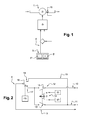
- the mobile device 1 of the fire vehicle or fire pump type, is equipped with a pump 2 for the delivery of a fire-extinguishing liquid, for example of the centrifugal pump type, coupled to a drive motor 3 whose regime is controlled solely by manual control means 4 constituted here by an electric circuit (hereinafter described in connection with the figure 2 ).
- the operator intervenes on a panel or a control interface 5, equipping the electrical circuit 4, to manually control the speed of the associated drive motor 3.
- This management of the drive speed 3 makes it possible to regulate the operation of the centrifugal pump 2, in order to adjust the discharge pressure P at the outlet of said pump 2 (that is to say at the level of the volute of the pump or of its discharge port), particularly depending on the context of intervention on the fire.
- the electric circuit 4 mainly comprises a common conductive path 9, corresponding to the ground or the positive potential, followed by two parallel conductive paths 10, 11 connected to the drive motor 3 and associated with a selector device 12.
- the selector device 12 in question consists of two switches 13, each mounted on one of the parallel conductive paths 10 and 11, associated with a control member 14 operable via the control panel 5.
- the selector device 12 is manually controllable by the pump driver from two keys (one “faster” 5 'and the other “less quickly” 5 ") of the control panel 5. Depending on the 5 'or 5 "key actuated, this action causes the closing of one of the conductive paths 10 or 11, and consequently modifies the speed of the associated drive motor 3.
- the mobile device 1 comprises safety means intended to overcome the exceeding by the discharge pressure P, at the output of the discharge pump 2, a predetermined maximum safety threshold said “Pa -lim ", corresponding for example to the maximum pressure value tolerated by said pump 2. For this, once the threshold Pa-lim exceeded, the safety means cause an automatic decrease in the discharge pressure P to a threshold "P-react", lower than "Pa-lim".
- the threshold Pa-lim is generally of the order of 17 or 20 bar (as a function of the discharge pump equipping the device); the P-react threshold is then preferably, respectively, of the order of 16 or 19 bars (ie Pa-lim minus 1 bar).
- the pressure switch 15 in question is installed closest to the pump, for example at its discharge orifice (or even within its volute), in particular so that the pressure drops do not affect the pressure measurement and the measured value is the most representative of the actual value in the pump casing.
- This pressure switch 15 is chosen so as to be able to detect the attainment of the thresholds Pa-lim and P-react above.
- a suitable equipment for this purpose is for example of the type configurable pressure switch, having thresholds Pa-lim and P-react adjustable; alternatively, the thresholds Pa-lim and P-react are specific to the pressure switch, said threshold P-react corresponding to the hysteresis of the pressure switch.
- the pump conductor can adjust this discharge pressure P at will by controlling the speed of the drive motor 3, this from a manual action on the control panel 5.
- the pressure switch 15 is not activated.
- the safety switch 16 is then, by default, connected to the first contact 17; the action on the selector device 12 from the control panel 5 makes it possible to close one of the "faster” or “slower” conducting paths 11, respectively causing acceleration or reduction of the engine speed.
- the safety means intervene to restore a pressure adapted discharge.
- the pressure switch 15 detects the fact that the discharge pressure P reaches the safety threshold Pa-lim. This pressure switch 15 then causes the operation of the safety switch 16, so as to connect it now to the contact "bypass"18; in this configuration, the action of the selector device 12 is deactivated and the path main conductor "slower" 11 is closed via the way "by-pass” 19.
- This particular configuration of the electrical circuit 4 then causes, on the one hand, a disconnection of the control panel 5 with respect to the drive motor 3, and on the other hand, a decrease in the speed of said drive motor 3 so as to reduce the discharge pressure P at the pump outlet.
- this structure of the security means 15, 16 equipping the mobile device 1, has the advantage of being particularly simple and effective for restoring a delivery pressure P adapted, when it has exceeded a safety threshold Pa -lim.
- This safety system 15, 16 thus enables the pump operator not to have to deal with the problems of variation of the pressure of the water source, which greatly contributes to facilitating its concentration on the extinguishing action of the water source. traffic light.
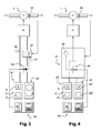
- FIGS 3 and 4 show two embodiments in which the mobile device 1 is equipped, in addition to the manual control means, means for automatic regulation of the discharge pressure P at the pump outlet.
- the automatic regulation means 21 are of the programmable logic controller type, for example of the regulator type "PID" ("Proportional Integral Derivative").
- Devices conforming to Figures 3 and 4 still include means 24 for the switching, by the pump driver, of the "manual" mode to the "automatic” mode, and vice versa, from an interface 25.
- the manual control means 20 are connected directly to the drive motor 3 of the delivery pump 2 via an electrical connection 26, and they comprise an interface 5 with two keys, one "faster 5 'and the other "slower” 5 "On its side, the programmable controller 21 is connected to the drive motor 3, the selection means 24 and the automatic control interface 22 (here shaped potentiometer).
- the manual control means 20 are connected to the drive motor 3 via the programmable controller 21.
- This programmable controller 21 then integrates the selection means 24 and is connected to the selection interface 25; it is also connected to the pressure reference input interface 22 (here two keys, one "increment” 22 'and the other "decrement” 22 "of the setpoint) and the control interface manual 5 (again with two keys 5 ', 5 ").
- the programmable controller 21 thus functions as a repeater for the manual control means 20, when they are selected and activated.
- the automatic regulation means 21 integrate the security means 27 which are associated with the selection means 24 and the pressure sensor 23. These safety means 27 are configured so that, when the engine speed is controlled by the manual control means 20 (due to the configuration of the selection means 24) and the discharge pressure P reaches the safety threshold Pa- lim, the selection means 24 switch in control of the discharge pressure P by the automatic control means 21, which ensure the return of the discharge pressure to the discharge setpoint, corresponding to the P-react threshold.
- the selection means 24 are controlled in a priority manner by the PLC 21, in relation to the selection interface 25.
- the pump conductor can not restore the manual control mode of the discharge pressure.
- the value of the discharge pressure P is adjusted by controlling the drive motor 3, either manually by the action on the manual interface 5, or automatically by entering a pressure setpoint at the interface 22.
- the pump conductor intervenes on the selection interface 25, so as to activate the manual control mode or automatic regulation of the discharge pressure P.
- the maximum value that can be assigned to the setpoint is lower than the threshold value Pa-lim.
- this automatic regulation ensures the return of the pressure discharge P up to the discharge setpoint input at the interface 22, corresponding to the threshold P-react.
- the safety threshold Pa-lim corresponds to the maximum pressure allowed by the discharge pump, which is generally 20 or 17 bar; the maximum setpoint of the automatic pressure regulation, corresponding to the maximum P-react threshold value, is equal to the threshold Pa-lim decreased by 1 bar, ie respectively 19 or 16 bar.
- a single interface may be provided for the manual control 5 and the entry of the instruction 22; the selection interface 25 will then allow the choice of the control mode of the discharge pressure P, and the single interface 5, 22 will allow the adjustment of the engine speed in manual mode or the adjustment of the discharge pressure setpoint in operating mode. automatic.
- the mobile devices in accordance with the invention have the advantage of offering a simple and effective management of the problems of increasing the discharge pressure beyond a certain threshold value, which may in particular cause damage.
- the associated discharge pump This invention also has the advantage of providing the pump driver wishing to work in manual mode, a low-pressure solution that avoids constantly monitoring whether the discharge pressure exceeds a predetermined maximum value.
Landscapes
- Engineering & Computer Science (AREA)
- Mechanical Engineering (AREA)
- General Engineering & Computer Science (AREA)
- Control Of Positive-Displacement Pumps (AREA)
- Control Of Vehicle Engines Or Engines For Specific Uses (AREA)
Applications Claiming Priority (1)
| Application Number | Priority Date | Filing Date | Title |
|---|---|---|---|
| FR0610929A FR2909888B1 (fr) | 2006-12-15 | 2006-12-15 | Perfectionnement aux dispositifs mobiles pour la lutte contre l'incendie, du type vehicules incendie ou motopompes incendie. |
Publications (1)
| Publication Number | Publication Date |
|---|---|
| EP1933035A2 true EP1933035A2 (de) | 2008-06-18 |
Family
ID=38232934
Family Applications (1)
| Application Number | Title | Priority Date | Filing Date |
|---|---|---|---|
| EP20070301678 Withdrawn EP1933035A2 (de) | 2006-12-15 | 2007-12-14 | Perfektionierung der Vorrichtungen zur Brandbekämpfung vom Typ Löschfahrzeug oder Motorpumpe |
Country Status (2)
| Country | Link |
|---|---|
| EP (1) | EP1933035A2 (de) |
| FR (1) | FR2909888B1 (de) |
Citations (1)
| Publication number | Priority date | Publication date | Assignee | Title |
|---|---|---|---|---|
| US5888051A (en) | 1994-08-05 | 1999-03-30 | Mcloughlin; John E. | Pump pressure control system |
Family Cites Families (2)
| Publication number | Priority date | Publication date | Assignee | Title |
|---|---|---|---|---|
| US3786869A (en) * | 1972-04-27 | 1974-01-22 | Loughlin J Mc | Nozzle pressure control system |
| DE3817018C2 (de) * | 1988-05-19 | 1997-07-17 | Iveco Magirus | Feuerlöschpumpen-Antriebsregelung |
-
2006
- 2006-12-15 FR FR0610929A patent/FR2909888B1/fr not_active Expired - Fee Related
-
2007
- 2007-12-14 EP EP20070301678 patent/EP1933035A2/de not_active Withdrawn
Patent Citations (1)
| Publication number | Priority date | Publication date | Assignee | Title |
|---|---|---|---|---|
| US5888051A (en) | 1994-08-05 | 1999-03-30 | Mcloughlin; John E. | Pump pressure control system |
Also Published As
| Publication number | Publication date |
|---|---|
| FR2909888A1 (fr) | 2008-06-20 |
| FR2909888B1 (fr) | 2009-02-06 |
Similar Documents
| Publication | Publication Date | Title |
|---|---|---|
| CA2756714C (fr) | Procede de commande pour systeme de securite survitesse de moteurs d'aeronef et circuit de commande pour mettre en oeuvre ledit procede | |
| FR2782691A1 (fr) | Systeme de direction pour des vehicules du type decouple avec un dispositif de securite | |
| EP0334723B1 (de) | Steuervorrichtung für einen hydraulischen doppelt wirkenden Arbeitszylinder | |
| FR2986398A1 (fr) | Dispositif de securite pour la commande d'un moteur comprenant une redondance des acquisitions d'une mesure de capteurs | |
| FR2824804A1 (fr) | Dispositif et procede de regulation de la puissance des moteurs d'un aeronef multimoteur a voilure tournante | |
| EP0238368B1 (de) | Speisesystem für Druckflüssigkeit | |
| EP1827978B1 (de) | Vorrichtung zur ausgabe einer genehmigung zum einwirken auf die betriebsbedingungen eines luftfahrzeugmotors und diese umfassendes motorsteuersystem | |
| FR2462599A1 (fr) | Systeme de servocommande, en particulier pour aeronef ou astronef | |
| EP0799766A1 (de) | Vorrichtung um die Geschwindigkeit eines Flugzeugs in einem vorgegebenen Bereich zu halten | |
| EP1933035A2 (de) | Perfektionierung der Vorrichtungen zur Brandbekämpfung vom Typ Löschfahrzeug oder Motorpumpe | |
| EP1342645A1 (de) | Hydraulische Lenkvorrichtung | |
| EP3601765A1 (de) | Verbesserte vorrichtung zur temporären erhöhung der turbomaschinenleistung | |
| FR2542276A1 (fr) | Dispositif de reglage du tangage d'un aeronef pendant des operations de decollage ou de tour de piste | |
| FR2721070A1 (fr) | Dispositif de surveillance et de détection automatique d'anomalies fonctionnelles sur un circuit d'alimentation en pression d'une pompe principale. | |
| FR3079800A1 (fr) | Circuit fluidique de freinage comprenant une vanne de securite, vehicule automobile comprenant un tel circuit de freinage et utilisation d'un tel vehicule | |
| FR2651541A1 (fr) | Circuit de commande pour un verin hydraulique travaillant avec une pompe a debit variable. | |
| EP1526033A1 (de) | Verfahren zur Handhabung der Betriebsarten eines Sitzes und diesen Verfahren anwendenten Sitz. | |
| EP1572521B1 (de) | Fahrzeuglenksystem | |
| FR2911283A1 (fr) | Perfectionnement aux dispositifs mobiles pour la lutte contre l'incendie du type vehicules incendie ou motopompe incendie | |
| EP2603922B1 (de) | Verfahren und vorrichtung zur steuerung der bewegung eines beweglichen teils eines trennschalters | |
| EP1956246A2 (de) | Perfektionierung der beweglichen Vorrichtungen zur Brandbekämpfung, die mit manuellen und automatischen Kontrollmitteln ausgestattet sind | |
| EP4346090B1 (de) | Motorsteuerungsvorrichtung und motorstart- und schutzsystem mit solch einer motorsteuerungsvorrichtung | |
| EP2646887B1 (de) | Druckmodulierendes sicherheitsventil | |
| WO2023202985A1 (fr) | Unite d'entrainement en rotation d'un outil anime et procede de controle associe | |
| EP0091348B1 (de) | Reglerventil für gleichzeitige Speisung hydraulischer Anlagen mit offener und geschlossener Mitte |
Legal Events
| Date | Code | Title | Description |
|---|---|---|---|
| PUAI | Public reference made under article 153(3) epc to a published international application that has entered the european phase |
Free format text: ORIGINAL CODE: 0009012 |
|
| AK | Designated contracting states |
Kind code of ref document: A2 Designated state(s): AT BE BG CH CY CZ DE DK EE ES FI FR GB GR HU IE IS IT LI LT LU LV MC MT NL PL PT RO SE SI SK TR |
|
| AX | Request for extension of the european patent |
Extension state: AL BA HR MK RS |
|
| STAA | Information on the status of an ep patent application or granted ep patent |
Free format text: STATUS: THE APPLICATION IS DEEMED TO BE WITHDRAWN |
|
| 18D | Application deemed to be withdrawn |
Effective date: 20150701 |