EP1933018A2 - Saugrohrregulatoren für Verbrennungsmotoren - Google Patents
Saugrohrregulatoren für Verbrennungsmotoren Download PDFInfo
- Publication number
- EP1933018A2 EP1933018A2 EP07024155A EP07024155A EP1933018A2 EP 1933018 A2 EP1933018 A2 EP 1933018A2 EP 07024155 A EP07024155 A EP 07024155A EP 07024155 A EP07024155 A EP 07024155A EP 1933018 A2 EP1933018 A2 EP 1933018A2
- Authority
- EP
- European Patent Office
- Prior art keywords
- regulator
- engine
- aperture
- passageway
- intake passageway
- Prior art date
- Legal status (The legal status is an assumption and is not a legal conclusion. Google has not performed a legal analysis and makes no representation as to the accuracy of the status listed.)
- Withdrawn
Links
- 238000002485 combustion reaction Methods 0.000 title claims abstract description 36
- 239000000446 fuel Substances 0.000 claims abstract description 51
- 230000008878 coupling Effects 0.000 claims abstract description 32
- 238000010168 coupling process Methods 0.000 claims abstract description 32
- 238000005859 coupling reaction Methods 0.000 claims abstract description 32
- 239000012530 fluid Substances 0.000 claims abstract description 29
- 238000004891 communication Methods 0.000 claims abstract description 8
- 238000011144 upstream manufacturing Methods 0.000 claims description 6
- 230000000007 visual effect Effects 0.000 claims description 4
- 238000010276 construction Methods 0.000 description 36
- 239000000203 mixture Substances 0.000 description 17
- 238000004519 manufacturing process Methods 0.000 description 8
- 230000007423 decrease Effects 0.000 description 6
- 230000008859 change Effects 0.000 description 5
- 238000000034 method Methods 0.000 description 5
- 230000008569 process Effects 0.000 description 3
- 238000001816 cooling Methods 0.000 description 2
- 230000009467 reduction Effects 0.000 description 2
- 230000000717 retained effect Effects 0.000 description 2
- 230000033228 biological regulation Effects 0.000 description 1
- 238000005266 casting Methods 0.000 description 1
- 239000003086 colorant Substances 0.000 description 1
- 238000003780 insertion Methods 0.000 description 1
- 230000037431 insertion Effects 0.000 description 1
- 238000012986 modification Methods 0.000 description 1
- 230000004048 modification Effects 0.000 description 1
- 230000008439 repair process Effects 0.000 description 1
- 239000007787 solid Substances 0.000 description 1
- 238000012360 testing method Methods 0.000 description 1
Images








Classifications
-
- F—MECHANICAL ENGINEERING; LIGHTING; HEATING; WEAPONS; BLASTING
- F02—COMBUSTION ENGINES; HOT-GAS OR COMBUSTION-PRODUCT ENGINE PLANTS
- F02D—CONTROLLING COMBUSTION ENGINES
- F02D9/00—Controlling engines by throttling air or fuel-and-air induction conduits or exhaust conduits
- F02D9/02—Controlling engines by throttling air or fuel-and-air induction conduits or exhaust conduits concerning induction conduits
-
- F—MECHANICAL ENGINEERING; LIGHTING; HEATING; WEAPONS; BLASTING
- F02—COMBUSTION ENGINES; HOT-GAS OR COMBUSTION-PRODUCT ENGINE PLANTS
- F02B—INTERNAL-COMBUSTION PISTON ENGINES; COMBUSTION ENGINES IN GENERAL
- F02B73/00—Combinations of two or more engines, not otherwise provided for
-
- F—MECHANICAL ENGINEERING; LIGHTING; HEATING; WEAPONS; BLASTING
- F02—COMBUSTION ENGINES; HOT-GAS OR COMBUSTION-PRODUCT ENGINE PLANTS
- F02D—CONTROLLING COMBUSTION ENGINES
- F02D11/00—Arrangements for, or adaptations to, non-automatic engine control initiation means, e.g. operator initiated
-
- F—MECHANICAL ENGINEERING; LIGHTING; HEATING; WEAPONS; BLASTING
- F02—COMBUSTION ENGINES; HOT-GAS OR COMBUSTION-PRODUCT ENGINE PLANTS
- F02D—CONTROLLING COMBUSTION ENGINES
- F02D9/00—Controlling engines by throttling air or fuel-and-air induction conduits or exhaust conduits
- F02D9/02—Controlling engines by throttling air or fuel-and-air induction conduits or exhaust conduits concerning induction conduits
- F02D2009/0201—Arrangements; Control features; Details thereof
- F02D2009/0298—Throttle control device with holding devices, i.e. to hold throttle in a predetermined position
Definitions
- This invention relates generally to internal combustion engines, and more particularly to intake manifold regulators for internal combustion engines.
- Regulators are often used to reduce the power output of an internal combustion engine. When used in combination with carbureted engines, such regulators are configured to not be easily removable.
- the present invention provides, in one aspect, an engine system configured to provide a plurality of engines having different power outputs at the same selected speed.
- the engine system includes a first engine having a first power output at the selected speed.
- the first engine includes a first engine housing, a first crankshaft rotatably supported in the first engine housing, a first cylinder, a first piston movable within the first cylinder, a first combustion chamber in fluid communication with the first cylinder, a first fuel system configured to provide fuel to the first combustion chamber, a first passageway configured to provide a fluid (e.g., air, fuel, or an air/fuel mixture) to the first combustion chamber, and a first regulator at least partially positioned in the first passageway.
- a fluid e.g., air, fuel, or an air/fuel mixture
- the first regulator is selected such that the first engine operates at the first power output at the selected speed.
- the first engine also includes a first coupling device configured to maintain the first regulator in the first passageway.
- the first coupling device is also configured to enable removal of the first regulator without disassembly of the first passageway.
- the engine system also includes a second engine having a second power output at the selected speed different from the first power output.
- the second engine includes a second engine housing, a second crankshaft rotatably supported in the second engine housing, a second cylinder, a second piston movable within the second cylinder, a second combustion chamber in fluid communication with the second cylinder, a second fuel system configured to provide fuel to the second combustion chamber, a second passageway configured to provide a fluid (e.g., air, fuel, or an air/fuel mixture) to the second combustion chamber, and a second regulator at least partially positioned in the second passageway.
- the second regulator is selected such that the second engine operates at the second power output at the selected speed, with the second power output being different from the first power output.
- the second engine also includes a second coupling device configured to maintain the second regulator in the second passageway. The second coupling device is also configured to enable removal of the second regulator without disassembly of the second passageway.
- Such an engine system may be used to manufacture engines, each engine having a distinct desired power output selectable from a range of power outputs, from a common engine configuration utilizing the same fuel calibration and the same fuel systems.
- first and second production runs of engines including substantially identical engine housings, crankshafts, cylinders, pistons, combustion chambers, fuel systems, and intake passageways may yield a first power output at a selected speed and a second power output (different than the first power output) at the selected speed, respectively, due to the differently-sized regulators chosen for the first and second production runs of engines.
- crankshafts camshafts
- pistons connecting rods
- cylinder heads or fuel systems to change the power output of the engines
- the engines may be pre-built and stored in inventory, with their respective regulators being added or changed later.
- the present invention provides, in another aspect, an internal combustion engine including an engine housing, a crankshaft rotatably supported in the engine housing, a cylinder, a piston movable within the cylinder, a combustion chamber in fluid communication with the cylinder, a fuel system configured to provide fuel to the combustion chamber, an intake passageway configured to provide a fluid (e.g., air, fuel, or an air/fuel mixture) to the combustion chamber, and a first regulator at least partially positioned in the intake passageway.
- the first regulator is selectable from a plurality of regulators.
- the engine also includes a coupling device configured to maintain the first regulator in the intake passageway.
- the first regulator is configured to be removed and replaced by a second regulator from the plurality of regulators without disassembly of the intake passageway.
- the present invention provides, in yet another aspect, a regulator adapted to be received within an aperture near an intake passageway in an internal combustion engine.
- the regulator includes a first portion configured to be exposed to an airflow in the intake passageway and selected such that the engine operates at a first power output at a selected speed when the first portion is exposed to the airflow, and a second portion configured to be received within the aperture and removably coupled to the engine without disassembly of the intake passageway.
- FIG. 1 is a perspective view of an internal combustion engine of the present invention.
- FIG. 2a is a partial cross-sectional view of the engine of FIG. 1 through section 2a-2a in FIG. 1 .
- FIG. 2b is a partial cross-sectional view similar to FIG. 2a , illustrating a second engine having substantially the same configuration of the engine of FIG. 1 .
- FIG. 3 is an exploded perspective view of a portion of the engine of FIG. 1 , illustrating a first construction of an intake manifold and a first construction of a group or family of differently-sized intake manifold regulators.
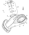
- FIG. 4 is an exploded perspective view of the intake manifold and one regulator, chosen from the group or family of differently-sized regulators in FIG. 3 .
- FIG. 5 is an assembled plan view of the intake manifold and regulator of FIG. 4 , illustrating a partial cutaway of the intake manifold to expose the regulator positioned in an intake passageway.
- FIG. 6 is a cross-sectional view of the intake manifold of FIG. 5 through section 6-6 in FIG. 5 .
- FIG. 7 is a cross-sectional view of the intake manifold and regulator of FIG. 5 through section 7-7 in FIG. 5 .
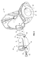
- FIG. 8 is an exploded perspective view of a portion of the engine of FIG. 1 , illustrating a second construction of an intake manifold and a second construction of one of a group or family of differently-sized intake manifold regulators.
- FIG. 9 is an exploded perspective view of a portion of the engine of FIG. 1 , illustrating a third construction of an intake manifold and a third construction of one of a group or family of differently-sized intake manifold regulators.
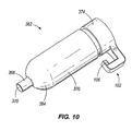
- FIG. 10 is a perspective view of a fourth construction of one of a group or family of differently-sized intake manifold regulators.
- FIG. 11 is an assembled view of the regulator of FIG. 10 and a fourth construction of an intake manifold, illustrating a partial cutaway of the intake manifold to expose the regulator positioned in an intake passageway of the intake manifold.
- FIG. 12 is a perspective view of a fifth construction of an intake manifold assembly according to the present invention.
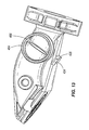
- FIG. 13 is a top view of the intake manifold used in the fifth construction.
- FIG. 14 is an exploded perspective view of the fifth construction, and illustrates a group or family of differently-sized intake manifold regulators used in the fifth construction.
- FIG. 15 is a side cross sectional view of the fifth construction, taken along line 15-15 of FIG. 12 .
- FIG. 1 illustrates a small, air-cooled, four-stroke internal combustion engine 10 having a single cylinder 12 (see FIG. 2a ) and a vertically-oriented crankshaft or output shaft 14.
- the engine 10 also includes a piston 15 coupled to the output shaft 14 by a connecting rod 17 for reciprocating movement in the cylinder 12, and a combustion chamber 16 in fluid communication with the cylinder 12.
- the engine 10 may be configured to operate, among other things, engine-driven outdoor power equipment (e.g., lawn mowers, lawn tractors, snow throwers, generators, pressure washers, etc.). When used in combination with a walk-behind lawn mower, for example, the engine 10 may be supported by a mower deck and the output shaft 14 may be coupled to a blade positioned beneath the mower deck. It should be understood that alternative constructions of the engine 10 may also include multiple-cylinder configurations or a horizontal output shaft configuration.
- engine-driven outdoor power equipment e.g., lawn mowers, lawn tractors, snow throwers, generators, pressure washers, etc
- the engine 10 also includes a blower housing 18 for providing a cooling airflow over the external components of the engine 10 (e.g., an outer housing or engine housing 22 and a cylinder head 26), an air cleaner 30 coupled to the blower housing 18 for providing a filtered airflow to the engine 10, a fuel system including a carburetor 34 that receives the filtered airflow from the air cleaner 30 and adds fuel to the filtered airflow to create a fuel/air mixture, and an intake manifold 38 coupled to the carburetor 34 for delivering the fuel/air mixture to the cylinder head 26.
- the engine 10 may include any of a number of different configurations of blower housings for providing the cooling airflow over the external components of the engine and/or air cleaners for providing the filtered airflow to the engine 10.
- the intake manifold 38 includes an inlet 42 configured to receive the fuel/air mixture from the carburetor 34, an outlet 46 configured to discharge the fuel/air mixture into the cylinder head 26, an interior wall 48, and an intake passageway 50 defined by the interior wall 48, through which the fuel/air mixture passes, extending between the inlet 42 and the outlet 46.
- the intake passageway 50 has a non-linear longitudinal axis 54, such that the fuel/air mixture passing through the intake passageway 50 travels a substantially arcuate flow path moving from the inlet 42 to the outlet 46.
- Alternative constructions of the intake manifold 38 may include any of a number of different configurations, in which the longitudinal axis 54 of the intake passageway 50 is substantially arcuate or substantially straight or linear.
- a family or a group 58 of interchangeable, differently-sized regulators is shown, any of which may be at least partially positioned in an airflow passageway or a fuel/air mixture passageway in the engine 10.
- any regulator from the group 58 may be coupled to the intake manifold 38.
- any regulator from the group 58 may be positioned in an airflow passageway in the engine 10 upstream of the carburetor 34.
- any regulator from the group 58 may be positioned in an airflow passageway in the air cleaner 30, or any regulator from the group 58 may be positioned in an airflow passageway between the air cleaner 30 and the carburetor 34.
- intake passageway should not be limited to the passageway through the intake manifold 38, but rather should include any airflow passageway upstream of the carburetor 34, or any fuel/air mixture passageway through the carburetor 34 or downstream of the carburetor 34.
- a combination of two or more regulators from the group 58 may be positioned in an airflow passageway in the engine 10 upstream of the carburetor 34 or a fuel/airflow passageway in the engine 10 downstream of the carburetor 34 to achieve a desired decrease in power output by the engine 10.
- the engine 10 is shown having one of the regulators 62 from the group 58 coupled to the intake manifold 38.
- the engine 10 therefore, is operable to achieve a first power output at a selected speed.
- a second engine 10a which may have - but need not have - substantially similar internal components as the first engine 10, is shown.
- the second engine 10a includes a second cylinder 12a that may be substantially similar to the cylinder 12, a second output shaft 14a that may be substantially similar to the output shaft 14, a second piston 15a that may be substantially similar to the piston 15, a second connecting rod 17a that may be substantially similar to the connecting rod 17, a second engine housing 22a that may be substantially similar to the engine housing 22, a second cylinder head 26a that may be substantially similar to the cylinder head 26, and a second air cleaner 30a that may be substantially similar to the air cleaner 30.
- Second fuel system or carburetor 34a is preferably substantially similar to the carburetor 34.
- Second intake manifold 38a may be substantially similar to the intake manifold 38.
- the second engine 10a utilizes a different regulator 62a from the group 58 than the engine 10.
- the engine 10a therefore, is operable to achieve a second power output different from the first power output of the engine 10 at the same selected speed.
- other components of the engine 10a such as the cylinder 12a, the output shaft 14a, the piston 15a, the connecting rod 17a, the engine housing 22a, the cylinder head 26a, the air cleaner 30a, the carburetor 34a, and the intake manifold 38a may be changed, either individually or in combination, to achieve the second or another different power output.
- the intake manifold 38 includes a wall 64 defining an aperture 66, positioned between the inlet 42 and the outlet 46, exposed to the intake passageway 50 for receiving one regulator selected from the group 58 (see also FIG. 5 ).
- the aperture 66 is configured as a stepped aperture 66 for receiving different portions of the regulator.
- Each of the regulators in the group 58 includes an interior portion (e.g., interior portions 70, 70a of regulators 62, 62a) that is at least partially positioned within the intake passageway 50, and a base or an exterior portion 74 that is external to the intake passageway 50. As shown in FIG.
- the exterior portion 74 includes a groove 78 extending around the outer periphery of the exterior portion 74, in which a seal 82 (e.g., an O-ring) is received to seal against the wall 64 to inhibit outside air from leaking into the intake passageway 50 through the aperture 66.
- a seal 82 e.g., an O-ring
- Alternative constructions of the intake manifold 38 and the regulators may include stepped or non-stepped apertures and corresponding stepped or non-stepped surfaces on the regulators.
- both the interior portions (e.g., interior portions 70, 70a) and the exterior portions 74 of the respective regulators have a generally cylindrical shape.
- the interior portions (e.g., interior portions 70, 70a) of the respective regulators are configured as cylinders having a spherical or dome-shaped distal end 84, a longitudinal axis 86, a length dimension D1 along the longitudinal axis 86, and a width dimension D2 transverse to the longitudinal axis 86 (see FIG. 5 ).
- the interior portions are configured as cylinders having a curved outer surface (e.g., curved outer surface 90 of the regulator 62), the width dimension D2 is equal to the outer diameter of the interior portions 70 (see also FIG. 3 ).
- Alternative constructions of the regulators may include interior portions having any of a number of different shapes.
- alternative constructions of the regulators may include interior portions, or portions of the regulators exposed to the intake passageway 50, configured as substantially flat plates oriented substantially transversely to the longitudinal axis 54 of the intake passageway 50.
- the regulator and/or the intake manifold may include an alignment feature to ensure proper alignment and orientation of the regulator in the intake passageway 50.
- alternative constructions of the regulators may include substantially conical-shaped interior portions having a longitudinal axis generally aligned with the longitudinal axis 54 of the intake passageway 50.
- regulators can be used, because it is the effective regulator surface area exposed (i.e., the portion of the regulator that comes into contact with the airflow or air/fuel mixture) to the airflow compared to the total cross-sectional area of the intake passageway 50, not the shape of the regulator, which primarily determines the change in engine power output.
- the diameter or the width dimension D2 of each of the interior portions (e.g., interior portions 70, 70a) of the respective regulators in the group 58 is substantially equal, while the length dimension D1 (see FIG. 5 ) of each of the interior portions of the respective regulators in the group 58 is different.
- each of the exterior portions 74 of the respective regulators in the group 58 is substantially the same size.
- any one of the regulators in the group 58 may be selected to be received within the stepped aperture 66 because the regulators share commonly-shaped exterior portions 74, and interior portions (e.g., interior portions 70, 70a) may have a common width dimension D2 that conform to the shape of the stepped aperture 66.
- a visual indicator e.g., a distinctive color, a symbol, etc.
- one of the regulators (e.g. the regulator 62) from the group 58 is selected to be received within the stepped aperture 66.
- the interior portion 70 is oriented within the intake passageway 50 such that the longitudinal axis 86 of the interior portion 70 is substantially transverse to the longitudinal axis 54 of the intake passageway 50.
- at least a portion of the air/fuel mixture passing through the intake passageway 50 must pass over the dome-shaped distal end 84 and the curved outer surface 90 of the interior portion 70 of the regulator 62 before being discharged from the outlet 46 of the intake manifold 38.
- the presence of the interior portion 70 of the regulator 62 in the intake passageway 50 effectively decreases the width or height of the intake passageway 50, causing a localized restriction in the flow path of the air/fuel mixture as it passes from the inlet 42 to the outlet 46.
- the spherical or dome-shaped distal ends 84 allow the regulators, particularly those in the group 58 having the longest length dimensions D1, to be positioned in close proximity to the interior wall 48. By configuring the regulators in the group 58 with the spherical or dome-shaped distal ends 84, as opposed to flat ends with sharp corners that disrupt flow, tighter control of the pressure drop over the interior portions (e.g., interior portions 70, 70a of FIG. 3 ) may be achieved.
- Tighter control of the power output of the engine e.g., engines 10, 10 of FIGS. 2a and 2b , respectively
- more precise control of the power output of the engine may be achieved utilizing the regulators with the spherical or dome-shaped distal ends 84 because of the absence of sharp corners (which can disrupt flow) on the interior portions.
- a cross-section of the intake passageway 50 at a location upstream of the regulator 62 is shown.
- the intake passageway 50 is configured with a substantially circular cross-sectional shape through a plane 94 positioned upstream of the regulator 62 and oriented substantially transversely to the longitudinal axis 54 of the intake passageway 50.
- the substantially circular cross-sectional shape of the intake passageway 50 with respect to the plane 94 defines a cross-sectional open area A1.
- Alternative constructions of the intake manifold 38a, 38b may include an intake passageway 50 having any of a number of different cross-sectional shapes.
- FIG. 7 illustrates a cross-section of the intake passageway 50 and regulator 62, taken through a plane 98 containing the longitudinal axis 86 of the interior portion 70 and oriented substantially transversely to the longitudinal axis 54 of the intake passageway 50.
- the presence of the interior portion 70 of the regulator 62 in the intake passageway 50 effectively decreases the cross-sectional open area A1 of the intake passageway 50.
- the presence of the interior portion 70 of the regulator 62 in the intake passageway 50 defines a cross-sectional open area A2 substantially less than the cross-sectional open area A1.
- the cross-sectional open area A2 may be no more than about 60 percent of the cross-sectional open area A1. In another combination of the intake manifold 38 and one of the regulators selected from the group 58, the cross-sectional open area A2 may be between about 25 percent and about 85 percent of the cross-sectional open area A1.
- a coupling device 102 may be utilized to secure one of the regulators selected from the group 58 to the intake manifold 38 and maintain the interior portion of the regulator (e.g., the interior portion 70 of the regulator 62) in the intake passageway 50.
- the coupling device 102 includes a coupler or a finger 106 extending from the exterior portion 74 of the regulator 62 and a groove or slot 110 formed in the intake manifold 38 around the aperture 66 and configured to receive the finger 106.
- the regulator 62 In positioning the regulator 62 in the intake passageway 50, the regulator 62 is oriented such that the finger 106 is aligned with an opening 114 that leads into the slot 110, the regulator 62 is inserted through the aperture 66, and the finger 106 is passed through the opening 114 and into the slot 110.
- the regulator 62 may be rotated about its longitudinal axis 86, causing the finger 106 to move within the slot 110 away from the opening 114.
- An abutment surface 118 at least partially defining the slot 110, therefore, inhibits the unintentional removal of the regulator 62 from the intake manifold 38 without the required rotation of the regulator 62 to align the finger 106 with the opening 114 in the slot 110.
- the coupling device 122 includes a coupler or a resilient tab 126, having an abutment surface 128, extending from the exterior portion 74 of the regulator 162, and an abutment surface 130 on the intake manifold 38 configured to be engaged by the abutment surface 128 of the resilient tab 126 to inhibit unintentional removal of the regulator 162 from the aperture 66.
- the regulator 162 In positioning the regulator 162 in the intake passageway 50, the regulator 162 is oriented such that the resilient tab 126 is aligned with the abutment surface 130 and the regulator 162 is inserted through the aperture 66.
- the resilient tab 126 To secure the regulator 162 to the intake manifold 38, continued insertion of the regulator 162 causes the resilient tab 126 to deflect by sliding contact between a ramp surface 134 on the resilient tab 126 and an engagement surface 138 on the intake manifold 38. When the regulator 162 is fully inserted into the stepped aperture 66, the resilient tab 126 snaps back to its undeflected shape, such that mutual abutment of the surfaces 128, 130 on the resilient tab 126 and the intake manifold 38 inhibit unintentional removal of the regulator 162 from the intake manifold 38.
- FIG. 9 yet another construction of a regulator 262 with another construction of a coupling device 142 is shown for securing the regulator 262 to the intake manifold 38, with like features and components having like reference numerals.
- the coupling device 142 includes an insert 146 coupled to the intake manifold 38, a coupler or a mounting flange 150 extending from the exterior portion 74 of the regulator 262, and a fastener 154 (e.g., a bolt or screw) inserted through an aperture 158 in the mounting flange 150 to threadably engage the insert 146 in the intake manifold 38.
- a fastener 154 e.g., a bolt or screw
- the insert 146 is molded into the intake manifold 38.
- the insert 146 may be omitted such that the fastener 154 is threaded directly into a threaded aperture or bore in the intake manifold 38.
- the coupling devices 102, 122, 142 may be omitted, and an interference fit between the exterior portion 74 and/or the interior portion 70 of the regulator 62, 162, or 262 and the stepped aperture 66 may be utilized to maintain the interior portion 70 of the regulator 62, 162, or 262 in the intake passageway 50.
- the O-ring 82 may provide the interference fit with the stepped aperture 66, such that the coupling devices 102, 122, 142 may be omitted.
- the intake manifold 338 is similar to the intake manifold 38 of FIGS. 3-7 , with like features having like reference numerals.
- the regulator 362 includes an interior portion 370 that is at least partially positioned within the intake passageway 50, and an exterior portion 374 that is external to the intake passageway 50.
- the exterior portion 374 includes a groove 378 extending around the outer periphery of the exterior portion 374, in which a seal 382 (e.g., an O-ring, see FIG.
- the regulator 362 is illustrated with a portion of the coupling device 102 (i.e., the finger 106), the regulator 362 may be configured to utilize any of the coupling devices 122, 142 illustrated in FIGS. 8 and 9 , respectively.
- the regulator 362 includes an axial locating post 368 extending from a spherical or dome-shaped end 384 of the interior portion 370.
- the post 368 includes a substantially flat distal end 370 that is engageable with the interior wall 48 of the intake manifold 338 (see FIG. 11 ).
- the post 368 has a length dimension D3 that, when the regulator 362 is inserted through the aperture 366, determines how much of the interior portion 370 is exposed to the air/fuel mixture in the intake passageway 50.
- the regulator 362 may be one of a family or group of regulators having axial locating posts of different length dimensions D3 to provide different amounts of restriction within the intake passageway 50.
- the tolerance stack-up of the resulting open area at the restriction may be reduced.
- the tolerance of the open area e.g., open area A2 of FIG. 7
- the tolerance of the length dimension D3 of the axial locating post 368 - rather than multiple values (e.g., the length dimension D1 of the interior portion 70 in FIG. 5 , the counter-bore depth of the stepped aperture 66 in FIG.
- the regulators in the family or group 58 may be sized to decrease the net horsepower of the unrestricted engine 10 between about 5 percent and about 25 percent or more.
- Such a reduction in the power output of the engine 10 is a function of the exposed area (i.e., the portion of the regulator 62 that comes into contact with the airflow or fuel/air mixture) of the regulator 62 in the intake passageway 50 - i.e., as the length dimension D1 increases, the cross-sectional open area A2 (see FIG. 7 ) decreases, thus restricting the amount of fuel/air mixture that can be effectively consumed by the engine 10 during operation.
- Such a reduction in power output may be achieved without any modifications to the calibration of the carburetor 34 or other fuel system, and without replacing the carburetor or other fuel system. In other words, no changes in the amount of fuel metered to the airflow by the carburetor 34 would be necessary to achieve the resultant decreases in power output for each engine-regulator combination.
- one regulator from the group 58 may be selected to achieve a power output of the engine 10 that is less than the unrestricted power output of the engine 10.
- the unrestricted power output of the engine 10 is determined, and a desired or a restricted power output is determined. Then, knowing the horsepower drop caused by each of the regulators in the group 58 from empirical testing performed on an engine having the same configuration as the engine 10, a particular regulator may be selected to achieve the desired power output of the engine 10, without altering or changing the fuel calibration of the carburetor 34 and without changing the engine castings. It is also desirable to use the same configuration of the engine housing 22.
- pistons 15, connecting rods 17, crankshafts 14, and the valve train may also be used, different configurations of the pistons, connecting rods, crankshafts, and the valve train may alternatively be used to achieve a greater number of variations of power output for the engine 10.
- Another method or process of using the family or group 58 of regulators with the engine 10 includes measuring the power output of the engine 10 using a first regulator from the group 58. If the measured power output of the restricted engine 10 does not match a desired power output, then the first regulator may be removed from the intake manifold 38 without disassembling the engine 10 or removing the intake manifold 38 from the cylinder head 26 or the carburetor 34. A second regulator from the group 58 may then be chosen to replace the first regulator in the intake manifold 38. This method or process of using the group 58 of regulators reduces the repair time or the rebuild time necessary for changing the power output of the engine 10.
- the existing regulator in the engine 10 may be replaced with another regulator from the group 58 to change the power output of the engine 10.
- “disassembly of the intake passageway” includes removing or disconnecting any component forming a portion of the intake passageway, including the carburetor 34 and the intake manifold 38.
- the first regulator may be removed and replaced by the second regulator merely by disconnecting the coupling device 102, 122, or 142, removing the first regulator from the aperture 66 along the longitudinal axis 86 of the first regulator, inserting the second regulator into the aperture 66 along the longitudinal axis 86 of the second regulator, and re-connecting the coupling device 102, 122, or 142.
- These steps to exchange the first regulator for the second regulator may occur without removing or disconnecting the carburetor 34 or the intake manifold 38, for example, from the engine 10.
- first and second production runs of engines 10, including substantially identical engine housings 22, output shafts 14, cylinders 12, pistons 15, combustion chambers 16, carburetors 34, and intake manifolds 38, may yield a first power output at a selected speed and a second power output (different than the first power output) at the selected speed, respectively, due to the differently-sized regulators chosen for the first and second production runs of engines 10.
- an existing production run of engines 10 incorporating one of the regulators from the group 58 may be re-worked to remove the existing regulators from the engines 10, which allowed the engines 10 to generate the first power output at the selected speed, and replace them with differently-sized regulators, which would allow the engines 10 to generate the second power output at the selected speed.
- the visual indicators may facilitate identification of the regulators on an assembly line during a production run or during re-work (i.e., repairing or rebuilding) of already-assembled engines so that the correct regulator is coupled to the engine.
- FIGS 12-15 depict another construction of the present invention.
- intake manifold assembly 438 includes a main body 439 having an inlet 442 and an outlet 443.
- Body 439 includes an intake passageway 450 defined by a wall 448.
- Intake assembly manifold assembly 438 also includes a regulator 462 that is disposed in a slot or aperture 466 (See Fig. 13 ) formed within wall 464.
- regulator 462 has a substantially planar outer surface 463 as part of its exterior portion 474, and an interior portion 470 having a fluid flow aperture 471 therein.
- Interior portion 470 is configured as a plate-like member in the depicted embodiment, although other constructions could be used.
- regulator 462 is retained by a coupling device that interconnects the exterior portion 474 of the regulator 462 to the intake manifold body 439.
- the coupling device includes a post 435 having a ramped surface 434 attached to body 439.
- Post 435 receives an aperture 430 of a resilient tab 426 that extends from exterior portion 474, and more particularly from outer surface 463 of regulator 462.
- a seal 482 (such as an O-ring) is received in a groove 478 formed in the end or exterior portion 474 of regulator 462.
- the regulator 462 is retained in place by having its end 484 disposed within a slot or recess 485, which in turn is formed in intake manifold body 439. See Figure 15 . This configuration reduces the tolerance stack-up issues discussed above in connection with the construction of Figures 8-11 .
- Figure 14 depicts a group or family 458 of regulators, each designed to achieve a different horsepower for the engine by varying the size of the effective fluid flow aperture 471 in the interior portion 470.
- the larger the size of the aperture the less restriction there is to fluid flow through intake passageway 450.
- the smaller the size of the aperture 471 the greater the surface area of the solid portion of interior portions 470, and consequently the greater the restriction to fluid flow through the intake passageway 450.
- a fluid flow aperture as part of the interior portion, it is apparent that the aperture as shown is more accurately depicted as a cylinder in that it has a length in the direction of fluid flow.
- non-cylindrical apertures could also be used, such as conical or polygonal shaped-openings; in general, it is the total amount of restriction to fluid flow which determines the amount of regulation, not the particular shape or configuration of the aperture.
- the group or family of regulators 462 is comprised of regulators 462a through 462h.
- Each of these regulators 462a through 462h has respective interior portions 470a through 470h.
- Each of the interior portions has formed therein a respective aperture 471a through 471h.
- Each of the apertures 471a through 471h has a different size, as clearly shown in Figure 14 .
- each of the regulators 462a through 462h results in a different horsepower for the engine.
Landscapes
- Engineering & Computer Science (AREA)
- Chemical & Material Sciences (AREA)
- Combustion & Propulsion (AREA)
- Mechanical Engineering (AREA)
- General Engineering & Computer Science (AREA)
- Cylinder Crankcases Of Internal Combustion Engines (AREA)
- Output Control And Ontrol Of Special Type Engine (AREA)
Applications Claiming Priority (1)
| Application Number | Priority Date | Filing Date | Title |
|---|---|---|---|
| US11/639,764 US7556019B2 (en) | 2006-12-15 | 2006-12-15 | Intake manifold regulators for internal combustion engines |
Publications (1)
| Publication Number | Publication Date |
|---|---|
| EP1933018A2 true EP1933018A2 (de) | 2008-06-18 |
Family
ID=39032239
Family Applications (1)
| Application Number | Title | Priority Date | Filing Date |
|---|---|---|---|
| EP07024155A Withdrawn EP1933018A2 (de) | 2006-12-15 | 2007-12-12 | Saugrohrregulatoren für Verbrennungsmotoren |
Country Status (4)
| Country | Link |
|---|---|
| US (3) | US7556019B2 (de) |
| EP (1) | EP1933018A2 (de) |
| CN (1) | CN101205837B (de) |
| AU (1) | AU2007237215B9 (de) |
Families Citing this family (6)
| Publication number | Priority date | Publication date | Assignee | Title |
|---|---|---|---|---|
| US7556019B2 (en) * | 2006-12-15 | 2009-07-07 | Briggs And Stratton Corporation | Intake manifold regulators for internal combustion engines |
| EP1967719B1 (de) * | 2007-03-09 | 2009-05-13 | Magneti Marelli S.p.A. | Ventil zur Steuerung des Luftdurchsatzes in einer Brennkraftmaschine |
| US8460421B2 (en) * | 2010-05-14 | 2013-06-11 | R2C Performance Products, LLC. | Velocity stack mounted air filter assembly |
| CN102914406B (zh) * | 2012-10-12 | 2014-09-10 | 南昌工控电装有限公司 | 一种歧管压力传感器组合线路板的快速标定方法及装置 |
| USD757119S1 (en) * | 2014-07-10 | 2016-05-24 | Cummins Power Generation Ip, Inc. | Throttle body |
| USD810139S1 (en) * | 2015-04-14 | 2018-02-13 | Henry Chan | Throttle body adapter |
Family Cites Families (50)
| Publication number | Priority date | Publication date | Assignee | Title |
|---|---|---|---|---|
| FR664130A (fr) | 1928-11-15 | 1929-08-29 | Appareil de rendement économique pour moteur à explosion | |
| GB359062A (en) | 1930-07-22 | 1931-10-22 | Albert Sykes | Improvements in and connected with atomisers for use with carburetters |
| GB437020A (en) | 1934-01-23 | 1935-10-23 | James Richard Mclean Keil | Improvements in or relating to charge mixing and heating devices and/or vaporisers for use in the cylinders of internal combustion engines |
| US4231383A (en) | 1970-03-06 | 1980-11-04 | Dresser Industries, Inc. | Method for controlling mass flow rate |
| US3937768A (en) | 1973-04-02 | 1976-02-10 | Colt Industries Operating Corporation | Variable venturi carburetor |
| JPS5241813B2 (de) | 1973-07-12 | 1977-10-20 | ||
| US4020805A (en) | 1973-07-12 | 1977-05-03 | Toyota Jidosha Kogyo Kabushiki Kaisha | Intake manifold flow equilizing means |
| US3994998A (en) | 1975-07-07 | 1976-11-30 | Fred Mineck | Carburetor with self adjusting venturi |
| JPS5427617A (en) | 1977-08-02 | 1979-03-01 | Toyota Motor Corp | Thermal insulator for carburetor |
| US4193947A (en) | 1978-03-20 | 1980-03-18 | Colt Industries Operating Corp. | Carbureting discharge means |
| US4274368A (en) | 1979-03-12 | 1981-06-23 | Shaffer Donald J | Tuneable intake manifold |
| DE3011595A1 (de) | 1980-03-26 | 1981-10-01 | Robert Bosch Gmbh, 7000 Stuttgart | Korrektureinrichtung fuer ein kraftstoffmesssystem bei einer brennkraftmaschine |
| US4760703A (en) | 1980-10-25 | 1988-08-02 | Yamaha Hatsudoki Kabushiki Kaisha | Induction system for internal combustion engines |
| US4900343A (en) | 1980-10-25 | 1990-02-13 | Yamaha Hatsudoki Kabushiki Kaisha | Induction system for internal combustion engines |
| US4487185A (en) | 1981-01-31 | 1984-12-11 | Suzuki Jidosha Kogyo Kabushiki Kaisha | Air-fuel mixture intake apparatus for internal combustion engines |
| US4384563A (en) | 1981-06-26 | 1983-05-24 | Gte Products Corporation | Apparatus for redirection of fuel-air mixture in carburetion system |
| US4364364A (en) | 1981-07-23 | 1982-12-21 | Cooper Industries, Inc. | Air-fuel ratio controller |
| US4492212A (en) | 1982-08-09 | 1985-01-08 | Dooley Richard L | Internal combustion engine of improved efficiency |
| JPS61169620A (ja) | 1985-01-22 | 1986-07-31 | Fuji Heavy Ind Ltd | 内燃機関の吸気制御装置 |
| US5020973A (en) | 1986-04-25 | 1991-06-04 | The Scott & Fetzer Company | Air compressor shroud |
| US4890586A (en) | 1986-08-06 | 1990-01-02 | Honda Giken Kogyo Kabushiki Kaisha | Intake device for an internal combustion engine |
| US4864991A (en) | 1987-12-01 | 1989-09-12 | Snyder Warren E | Method and apparatus for controlling air to gas ratio of gaseous fueled engines |
| US4805573A (en) | 1988-02-22 | 1989-02-21 | General Motors Corporation | Engine with variable area intake passages |
| JPH0333428A (ja) | 1989-06-29 | 1991-02-13 | Suzuki Motor Corp | 内燃機関の吸気装置 |
| US4928638A (en) | 1989-09-12 | 1990-05-29 | Overbeck Wayne W | Variable intake manifold |
| IT1246830B (it) * | 1990-07-10 | 1994-11-28 | Gd Spa | Dispositivo per il taglio trasversale in spezzoni di un nastro mobile di moto continuo lungo un percorso determinato. |
| US5255649A (en) | 1991-02-21 | 1993-10-26 | Yamaha Hatsudoki Kabushiki Kaisha | Intake air control system for the engine |
| JP3033428B2 (ja) | 1994-03-28 | 2000-04-17 | 凸版印刷株式会社 | 多層プラスチック容器の製造方法 |
| IT1280978B1 (it) | 1995-10-17 | 1998-02-11 | Ferrari Spa | Sistema di aspirazione a capacita' variabile per un motore endotermico di un veicolo. |
| BR9709517A (pt) | 1996-06-03 | 1999-08-10 | Mann & Hummel Filter | Dispositivo de admissão de ar |
| GB2316721B (en) | 1996-09-02 | 2000-11-22 | Aes Eng Ltd | Mechanical seal |
| US5749342A (en) | 1996-09-03 | 1998-05-12 | Chao; Raymond | Moveable aperture for alteration of intake manifold cross sectional area |
| US5947085A (en) * | 1997-05-27 | 1999-09-07 | Deal; Richard E. | Method and device for automatically controlling the fluid intake of an engine |
| JP3562235B2 (ja) | 1997-07-03 | 2004-09-08 | 日産自動車株式会社 | 内燃機関の吸気騒音低減装置 |
| US5924398A (en) | 1997-10-06 | 1999-07-20 | Ford Global Technologies, Inc. | Flow improvement vanes in the intake system of an internal combustion engine |
| US5864991A (en) * | 1998-01-02 | 1999-02-02 | Burns; Gary | Mobile booth system |
| US6332442B1 (en) | 1998-04-16 | 2001-12-25 | Toyoda Gosei Co., Ltd. | Intake air duct |
| US6481425B1 (en) | 1999-10-12 | 2002-11-19 | Siemens Vdo Automotive Inc. | Air quantity control for smooth switching in gasoline direct injection engine |
| US6497245B1 (en) * | 1999-10-13 | 2002-12-24 | Denso Corporation | Intake air controller for internal combustion engine and manufacturing the same |
| US6299144B1 (en) | 2000-03-07 | 2001-10-09 | Marc W. Salvisberg | Carburetor device with additional air-fuel flow apertures |
| US6830238B1 (en) | 2001-05-10 | 2004-12-14 | Stephen H Kesselring | Air bleed control device for carburetors |
| EP1283353B1 (de) | 2001-08-10 | 2008-05-28 | Ford Global Technologies, Inc. | Ansaugkrümmer |
| US6748915B2 (en) | 2001-09-27 | 2004-06-15 | Siemens Vdo Automotive Inc. | Clampless connection between vehicle engine throttle body and air resonator |
| US6564767B1 (en) | 2002-05-28 | 2003-05-20 | Slp Performance Parts, Inc. | Method for tuning internal combustion engine manifolds |
| US6827054B2 (en) | 2002-12-06 | 2004-12-07 | Daimlerchrysler Corporation | Integrated inlet manifold tuning valve and charge motion control device for internal combustion engines |
| JP2004232594A (ja) * | 2003-01-31 | 2004-08-19 | Denso Corp | 吸気装置 |
| PT1770263E (pt) * | 2005-10-03 | 2009-03-10 | Magneti Marelli Spa | Colector de admissão de um sistema de turbulência para um motor de combustão interna |
| US7299688B2 (en) * | 2005-11-02 | 2007-11-27 | Salvisberg Marc W | Device and method for maximizing internal combustion engine horsepower for a preselected RPM range |
| US7280905B1 (en) | 2006-04-15 | 2007-10-09 | Salvisberg Marc W | System and method for maximizing power output from an internal combustion engine |
| US7556019B2 (en) * | 2006-12-15 | 2009-07-07 | Briggs And Stratton Corporation | Intake manifold regulators for internal combustion engines |
-
2006
- 2006-12-15 US US11/639,764 patent/US7556019B2/en not_active Expired - Fee Related
-
2007
- 2007-11-28 AU AU2007237215A patent/AU2007237215B9/en not_active Ceased
- 2007-12-12 EP EP07024155A patent/EP1933018A2/de not_active Withdrawn
- 2007-12-14 CN CN200710194339XA patent/CN101205837B/zh not_active Expired - Fee Related
-
2009
- 2009-03-03 US US12/397,054 patent/US7717078B2/en not_active Expired - Fee Related
- 2009-03-03 US US12/397,049 patent/US7669572B2/en not_active Expired - Fee Related
Also Published As
| Publication number | Publication date |
|---|---|
| AU2007237215B9 (en) | 2009-09-24 |
| US20090159035A1 (en) | 2009-06-25 |
| AU2007237215B2 (en) | 2009-09-03 |
| US20090159036A1 (en) | 2009-06-25 |
| US7556019B2 (en) | 2009-07-07 |
| CN101205837A (zh) | 2008-06-25 |
| US20080141969A1 (en) | 2008-06-19 |
| US7717078B2 (en) | 2010-05-18 |
| AU2007237215A1 (en) | 2008-07-03 |
| CN101205837B (zh) | 2011-06-22 |
| US7669572B2 (en) | 2010-03-02 |
Similar Documents
| Publication | Publication Date | Title |
|---|---|---|
| US7717078B2 (en) | Intake manifold regulators for internal combustion engines | |
| US12215659B2 (en) | Electronic fuel injection throttle body assembly | |
| US7806103B2 (en) | Integrated valve device | |
| AU2009298633B2 (en) | Crankcase pressure regulator for an internal combustion engine | |
| US11401845B2 (en) | Engine device | |
| JP2003343389A (ja) | 一体形フロー・リミッタ/フィルタを備えた高圧コネクタ | |
| CA1063896A (en) | Fuel spray bar and pressure regulator assembly for an internal combustion engine | |
| US20220316370A1 (en) | Engine Device | |
| US20130104817A1 (en) | Engine assembly including crankcase ventilation system | |
| EP3059435A1 (de) | Blowby-gasbehandlungsvorrichtung | |
| JP4233675B2 (ja) | 燃料噴射装置のバイパス空気通路構造および燃料噴射装置ユニット組立体 | |
| JP7067243B2 (ja) | 内燃機関 | |
| US20230366331A1 (en) | Turbocharger Lubrication System For A Two-Stroke Engine | |
| KR101896205B1 (ko) | 부속 부분을 포함하는 내연기관 | |
| US4231390A (en) | Pressure regulator system | |
| KR102050914B1 (ko) | 전자식 스로틀밸브 장치 | |
| US9541033B2 (en) | Gaseous fuel and air mixing venturi insert device for carburetor | |
| CN204921071U (zh) | 阀门驱动组件、发动机系统、以及排气摇臂 | |
| US20250137424A1 (en) | Throttle body adapter | |
| US9624881B2 (en) | Airbox for engine | |
| US20080257307A1 (en) | Converting an electronic fuel injection engine to a carbureted engine |
Legal Events
| Date | Code | Title | Description |
|---|---|---|---|
| PUAI | Public reference made under article 153(3) epc to a published international application that has entered the european phase |
Free format text: ORIGINAL CODE: 0009012 |
|
| AK | Designated contracting states |
Kind code of ref document: A2 Designated state(s): AT BE BG CH CY CZ DE DK EE ES FI FR GB GR HU IE IS IT LI LT LU LV MC MT NL PL PT RO SE SI SK TR |
|
| AX | Request for extension of the european patent |
Extension state: AL BA HR MK RS |
|
| STAA | Information on the status of an ep patent application or granted ep patent |
Free format text: STATUS: THE APPLICATION IS DEEMED TO BE WITHDRAWN |
|
| 18D | Application deemed to be withdrawn |
Effective date: 20140701 |