EP1932423B1 - Spraying device - Google Patents
Spraying device Download PDFInfo
- Publication number
- EP1932423B1 EP1932423B1 EP07023621.1A EP07023621A EP1932423B1 EP 1932423 B1 EP1932423 B1 EP 1932423B1 EP 07023621 A EP07023621 A EP 07023621A EP 1932423 B1 EP1932423 B1 EP 1932423B1
- Authority
- EP
- European Patent Office
- Prior art keywords
- bypass line
- line
- carrier liquid
- pump
- spraying device
- Prior art date
- Legal status (The legal status is an assumption and is not a legal conclusion. Google has not performed a legal analysis and makes no representation as to the accuracy of the status listed.)
- Active
Links
- 238000005507 spraying Methods 0.000 title claims description 14
- 239000007788 liquid Substances 0.000 claims description 69
- 239000013543 active substance Substances 0.000 claims description 50
- 239000007921 spray Substances 0.000 claims description 39
- 238000010790 dilution Methods 0.000 claims description 5
- 239000012895 dilution Substances 0.000 claims description 5
- 239000002689 soil Substances 0.000 claims 2
- 238000007599 discharging Methods 0.000 claims 1
- 238000005086 pumping Methods 0.000 claims 1
- 239000004480 active ingredient Substances 0.000 description 25
- 239000003814 drug Substances 0.000 description 16
- 229940079593 drug Drugs 0.000 description 16
- 239000003795 chemical substances by application Substances 0.000 description 11
- 238000002347 injection Methods 0.000 description 6
- 239000007924 injection Substances 0.000 description 6
- 239000000203 mixture Substances 0.000 description 5
- XLYOFNOQVPJJNP-UHFFFAOYSA-N water Substances O XLYOFNOQVPJJNP-UHFFFAOYSA-N 0.000 description 5
- 238000000034 method Methods 0.000 description 4
- 238000006073 displacement reaction Methods 0.000 description 3
- 239000012530 fluid Substances 0.000 description 2
- 238000007726 management method Methods 0.000 description 2
- 230000007246 mechanism Effects 0.000 description 2
- 230000008569 process Effects 0.000 description 2
- 230000004044 response Effects 0.000 description 2
- 230000007480 spreading Effects 0.000 description 2
- 230000004913 activation Effects 0.000 description 1
- 230000008901 benefit Effects 0.000 description 1
- 230000008859 change Effects 0.000 description 1
- 230000001934 delay Effects 0.000 description 1
- 238000012377 drug delivery Methods 0.000 description 1
- 238000005516 engineering process Methods 0.000 description 1
- 230000007613 environmental effect Effects 0.000 description 1
- 239000003337 fertilizer Substances 0.000 description 1
- 230000006870 function Effects 0.000 description 1
- 238000005259 measurement Methods 0.000 description 1
- 238000002360 preparation method Methods 0.000 description 1
- 230000009467 reduction Effects 0.000 description 1
Images

Classifications
-
- A—HUMAN NECESSITIES
- A01—AGRICULTURE; FORESTRY; ANIMAL HUSBANDRY; HUNTING; TRAPPING; FISHING
- A01M—CATCHING, TRAPPING OR SCARING OF ANIMALS; APPARATUS FOR THE DESTRUCTION OF NOXIOUS ANIMALS OR NOXIOUS PLANTS
- A01M7/00—Special adaptations or arrangements of liquid-spraying apparatus for purposes covered by this subclass
- A01M7/0089—Regulating or controlling systems
- A01M7/0092—Adding active material
Definitions
- the invention relates to an injection device according to the preamble of claim 1.
- Such an injection device is for example in the US-A-5,310,113 described (see also eg DE-A-10 2004 047 585 ).
- This spraying device has a carrier liquid container in which water or liquid fertilizer is contained as the carrier liquid.
- a feed pump the carrier liquid to the spray nozzles and a circulation pump is supplied to the spray nozzles in a separate manner, the active ingredient from a drug reservoir.
- the active ingredient is first fed directly to the spray nozzles in the carrier liquid, mixed with it and then applied the active agent with the carrier liquid in a mixed manner on the spray nozzles.
- the agent agent filled in the drug reservoir can be filled undiluted from the drug reservoir via a feed line.
- the refilling of the active ingredient from the drug reservoir into the drug reservoir is determined by a minimum level sensor and a maximum level sensor located on the drug reservoir. These two sensors control an inlet valve, which is located in the feed line, which is arranged between the active substance reservoir and the drug reservoir.
- Predilution operation is possible.
- the active ingredient and carrier liquid are then in a certain ratio to one another via a predilution pump passed into the drug reservoir, so that the drug passes prediluted in the drug reservoir.
- the circulation pump then sucks the prediluted or undiluted drug agent. So there is always a certain amount of active ingredient or pre-diluted drug amount present in the drug reservoir.
- the contents of this container must be disposed of after completion of the application work. It must always be thinned much more active ingredient than is actually needed for the application.
- the invention has for its object to maintain in a simple manner the smallest possible amounts of active ingredient in the spray system between the respective drug tank and the spray nozzles in the lines with sufficient fluidity and to create the ability to quickly adjust the applied volume flow of active agent to the respective needs.
- At least one active ingredient can be fed into a at least one pressurized bypass line of the carrier liquid by means of at least one pump in a pre-dilution in a pre-dilution in at least one pressurized bypass line that the at least one the at least with the carrier liquid pre-diluted and under pressure active agent containing bypass line opens into the at least one leading to the spray nozzle carrier liquid line.
- the active agent is fed continuously during the injection process in a pressurized carrier fluid leading bypass line for predilution.
- the bypass line leading the prediluted active agent agent opens into the carrier fluid line leading to the spray nozzles, in which then the final carrier liquid agent concentration for producing the spray mixture which is applied via the spray nozzles is produced in mixing orphan
- the active agent agent is fed to the pre-dilution via a metering pump in the carrier liquid containing and pressurized bypass line.
- This predilution method of the active ingredient means that the high requirements of environmental safety are easily met in a simple manner.
- the preparation of the pre-dilution with a constant mixing ratio is carried out with the volume flow which corresponds to the demand resulting from the current travel speed and the actual working width.
- each bypass line a device is arranged, with which the flow rate can be adjusted in the respective bypass line.
- the device for adjusting the flow rate may be an adjustable flow valve.
- a mixing chamber is arranged at the point where the bypass line opens into the carrier liquid line.
- a simple and continuous feeding of the active agent into the carrier liquid of the bypass line is achieved by arranging in the bypass line an engine driven by the liquid stream flowing in the bypass line such that the engine drives at least one pump which pumps an active substance and feeds it into the bypass line.
- the active ingredient line which in each case comes from the active ingredient pump, can open into the bypass line in front of or behind the drive motor in the flow direction.
- each of the active ingredient pump delivering the line before the drive motor in the bypass line has the advantage that the active agent in the drive motor is very intense mixed with the carrier liquid to form a homogeneous liquid.
- This type of feed must be taken into account with regard to the metering accuracy with respect to the Vormiochungstechniks of active ingredient to carrier liquid with respect. Feeded amount of active ingredient. This is not necessary if the respectively coming from the drug pump coming active ingredient line behind the drive motor behind the Bypass line opens. In this case, depending on the properties of the active ingredient, it may be necessary to provide for a correspondingly good mixing of active ingredient with carrier liquid by suitable means with regard to the mixing property of the active ingredient with the carrier liquid.
- the bypass line is divided into a number corresponding to the number of partial widths of the spray bar arrangement behind the drive motor or the flow sensor and the feed point of the at least one active ingredient line in the bypass line, that number of partial bypass lines the carrier liquid line is divided into associated part width lines in front of each part of the spray bar arrangement in that a partial bypass line opens into a mixing chamber arranged in the part width carrier liquid line, that an adjustable flow valve is arranged in each part width bypass line.
- a simple embodiment of the flow valves can be achieved in that the flow valves arranged in the part-width bypass line are designed as adjustable diaphragms.
- a further simple configuration of the throughflow valves can be achieved in that the flow valves arranged in the part-width bypass line are designed as proportional orifices or restrictors.
- the active agent concentration corresponding to the desired use containers to the respective conditions of use such as site-specific Management, driving speed and working width and required amount of active ingredient per unit area to be able to provide that the arranged in the bypass lines or the Generalbreitenbypass Vogelen flow valves via an electronic control device as a function of the pressure prevailing in the carrier liquid pressure and / or in response to a travel or vehicle speed signal can be adjusted over the ground surface moving sprayer and / or depending on the current current, related to the processed bottom surface demand for active agent.
- the basic idea on which the invention is based is that as continuous as possible metering and ready mixing of active agent agents with carrier liquid take place only in the region of the partial widths in the distributor bar region. Furthermore, a negative pressure situation in the possibly highly viscous undiluted active agent area is avoided by the immediate arrangement of the metering pump for the undiluted active agent in the area of the active substance container and the feed of the active agent via the Wirkstoffstoffstoffstoffschosierpumpe in the carrier liquid of the pressurized bypass line.
- the inventive design of the continuous introduction of the active ingredient in the carrier liquid in a pressurized bypass line and the continuous introduction of the prediluted active ingredient in the carrier liquid in the partial width and the inventive design of the sprayer is a quick response to a change in the applied active agent concentration in the Carrier liquid reached and guaranteed. critical in that the active agent is fed in both concentrated and prediluted form, each in a continuous manner into the carrier liquid and mixed in continuously.
- Trained as a sprayer agricultural sprayer for spreading sprays has a storage tank 1, in which the carrier liquid, primarily water.
- a suction line 2 leads to a driven by a power source pump 3.
- the output line 4 of the pump 3 leads to the trained as injection pressure regulator 5 metering.
- a return line 6 leads back into the storage tank 1.
- the metering valve 5 which is designed for example as a 3-way valve is arranged in a closed pressure control loop to ensure in all operating situations, the optimum operating point of the nozzle 7 in terms of spray cone and droplet size.
- the carrier liquid line 8 coming from the metering device 5 branches off at the point 9, which is located in the vicinity of the sprayer boom, into individual part-width lines 10 which respectively lead to a partial width of the sprayer boom and the spray nozzles 7 arranged there.
- a part-width valve 11 is arranged in each part-width line 10.
- a mixing chamber 12 is arranged in the region of the spray boom in each partial width. From this mixing chamber 12, each part-width line 10 leads to the individual spray nozzles arranged on the spray boom.
- These spray nozzles 7 may be associated with a nozzle valve 13, via which the liquid supply to each spray nozzle 7 is shut off separately.
- Each active agent agent 14 to be delivered is assigned its own metering pump 15, 16, which is driven in each case by a motor 17.
- the active agent pumps 15, 16 are designed as adjustable pumps and can be adjusted by hand in the embodiment by means of a manual adjusting mechanism. From the coming of the carrier liquid pump 3 pressure line 4 branches off before the metering valve 5 at the branching point 18, a bypass line 19 from. This under pressure and filled with carrier liquid bypass line 19 leads to the form of a water hydraulic motor drive motor 17 for driving the active agent pumps 15, 16.
- a volume flow-proportional drive for the water hydraulic motor 17 in the carrier liquid leading bypass line 19 is installed, its output simultaneously drives the two active agent pumps 15, 16 with manual adjustment. It can also be with same result electric motors or oil hydraulic motors are used, which are guided by a carrier liquid volume flow sensor.
- each section bypass line 19" an adjustable valve 24, in the exemplary embodiment, an adjustable proportional shutter arranged.
- the active agent agent is first prepared into a premix and then mixed with the carrier liquid to the final spray mixture in a mixing chamber 12 of the part width lines 10.
- the premix has an active agent concentration, which at the variable displacement pumps 15, 16
- the variable displacement pumps 15, 16 are manually adjusted to produce the premix prior to use while the respective proportional orifice 24 processes the variable parameters during use by adjusting the volume flow of the premix to the particular section.
- the proportional apertures 24 are correspondingly controlled via an electronic control 25.
- controller 25 From the controller 25 can be switched on or off by the activation of the respective section valve 11 each Operake corresponding to the respective required working width. It is also possible, as indicated, via the electronic control 25, via the individual nozzles 7 associated nozzle valves 13 (only one of which is shown) to control this, so that each individual nozzle 7 can be shut off or switched accordingly, so that accordingly the spray width of a nozzle 7, the actual spreading width can be changed.
- each active agent pump 15, 16 is assigned its own drive motor 17, as well as each Agentstoffvorschmischungs bypass line 19 'separate adjustment valves 24, in the exemplary embodiment adjustable proportional aperture 24, which are independently controlled, is assigned.
- each active agent pump 15, 16 is assigned its own drive motor 17, as well as each Agentstoffvorschmischungs bypass line 19 'separate adjustment valves 24, in the exemplary embodiment adjustable proportional aperture 24, which are independently controlled, is assigned.
- a complete range of functionalities for site-specific direct injection is achieved.
- a separate Dosierverstellpumpe 15, 16 is provided, which is followed by a Verstellblende 24 for each section.
- the metered addition of the active agent means exactly At the time before the end of the application, it is stopped that the remaining quantities in the tubes for the treatment of the remaining area are exactly sufficient All that is required is, of course, at least approximately the same tube volumes in all the strands supplying the partial widths.
Description
Die Erfindung betrifft eine Spritzeinrichtung gemäß dem Oberbegriff des Patentanspruches 1.The invention relates to an injection device according to the preamble of
Eine derartige Spritzeinrichtung ist beispielsweise in der
Diese Spritzvorrichtung weist einen Trägerflüssigkeitsbehälter auf, in dem als Trägerflüssigkeit Wasser oder Flüssigdünger enthalten isc. Über eine Förderpumpe wird die Trägerflüssigkeit den Spritzdüsen und über eine Zirkulationspumpe wird den Spritzdüsen in getrennter Weise der Wirkstoff aus einem Wirkstoffvorbehälter zugeleitet. Somit wird der Wirkstoff erst unmittelbar an den Spritzdüsen in die Trägerflüssigkeit eingespeist, mit ihr vermischt und dann das Wirkstoffmittel mit der Trägerflüssigkeit in vermischter Weise über die Spritzdüsen ausgebracht.This spraying device has a carrier liquid container in which water or liquid fertilizer is contained as the carrier liquid. About a feed pump, the carrier liquid to the spray nozzles and a circulation pump is supplied to the spray nozzles in a separate manner, the active ingredient from a drug reservoir. Thus, the active ingredient is first fed directly to the spray nozzles in the carrier liquid, mixed with it and then applied the active agent with the carrier liquid in a mixed manner on the spray nozzles.
In einer ersten Ausführung kann das in dem Wirkstoffvorbehälter eingefüllte Wirkstoffmittel unverdünnt aus dem Wirkstoffvorratsbehälter über eine Zulaufleitung eingefüllt werden. Das Nachfüllen des Wirkstoffmittels aus dem Wirkstoffvorratsbehälter in den Wirkstoffvorbehälter wird über einen minimalen Füllstandssensor und einem maximalen Füllstandssensor, die an dem Wirkstoffvorbehälter angeordnet sind, bestimmt. Diese beiden Sensoren steuern ein Zulaufventil an, welches sich in der Zulaufleitung, die zwischen dem Wirkstoffvorratsbehälter und dem Wirkstoffvorbehälter angeordnet ist, befindet.In a first embodiment, the agent agent filled in the drug reservoir can be filled undiluted from the drug reservoir via a feed line. The refilling of the active ingredient from the drug reservoir into the drug reservoir is determined by a minimum level sensor and a maximum level sensor located on the drug reservoir. These two sensors control an inlet valve, which is located in the feed line, which is arranged between the active substance reservoir and the drug reservoir.
Des Weiteren ist ein sog. Vorverdünnungsbetrieb möglich. Hierzu wird dann über eine Vorverdünnungspumpe Wirkstoff und Trägerflüssigkeit in einem bestimmten Verhältnis zueinander in den Wirkstoffvorbehälter geleitet, so dass der Wirkstoff vorverdünnt in den Wirkstoffvorbehälter gelangt.Furthermore, a so-called. Predilution operation is possible. For this purpose, the active ingredient and carrier liquid are then in a certain ratio to one another via a predilution pump passed into the drug reservoir, so that the drug passes prediluted in the drug reservoir.
Aus diesem Wirkstoffvorbehälter saugt die Zirkulationspumpe dann das vorverdünnte oder unverdünnte Wirkstoffmittel an. Es ist also immer eine bestimmte Wirkstoffmittelmenge oder vorverdünnte Wirkstoffmittelmenge in dem Wirkstoffvorbehälter vorhanden. Der Inhalt dieses Behälters muss nach Beendigung der Ausbringarbeit entsorgt werden. Es muss auch immer wesentlich mehr Wirkstoff vorverdünnt werden als tatsächlich für das Ausbringen benötigt wird.From this drug reservoir, the circulation pump then sucks the prediluted or undiluted drug agent. So there is always a certain amount of active ingredient or pre-diluted drug amount present in the drug reservoir. The contents of this container must be disposed of after completion of the application work. It must always be thinned much more active ingredient than is actually needed for the application.
Der Erfindung liegt die Aufgabe zugrunde, in einfacher Weise möglichst geringe Wirkstoffmengen in dem Spritzsystem zwischen dem jeweiligen Wirkstofftank und den Spritzdüsen in den Leitungen mit ausreichender Fließfähigkeit vorzuhalten und die Möglichkeit zu schaffen, den ausgebrachten Volumenstrom an Wirkstoffmittel dem jeweiligen Bedarf schnell anpassen zu können.The invention has for its object to maintain in a simple manner the smallest possible amounts of active ingredient in the spray system between the respective drug tank and the spray nozzles in the lines with sufficient fluidity and to create the ability to quickly adjust the applied volume flow of active agent to the respective needs.
Diese Aufgabe wird erfindungsgemäß dadurch gelöst (siehe Anspruch 1), dass zumindest ein Wirkstoff in einem vor Arbeitsbeginn bestgelegten und eingestellten konstanten Mengenverhältnis zur Trägerflüssigkeit zunächst zur Vorverdünnung in zumindest eine unter Druck stehende Bypassleitung der Trägerflüssigkeit mittels zumindest einer Pumpe einspeisbar ist, dass die zumindest eine das zumindest mit der Trägerflüssigkeit vorverdünnte und unter Druck stehende Wirkstoffmittel enthaltende Bypassleitung in die zumindest eine zu den Spritzdüsen führende Trägerflüssigkeitsleitung mündet. Infolge dieser Maßnahme wird kontinuierlich nur so viel Wirkstoffmittel mit der Trägerflüssigkeit vorverdünnt und gleichzeitig in das Spritzsystem eingespeist, wie tatsächlich benötigt wird. Es erfolgt keine absatzweise Vorverdünnung des Trägermittels in einem separaten Vorratsbehälter. Vielmehr wird das Wirkstoffmittel während des Spritzvorganges kontinuierlich in eine unter Druck stehende Trägerflüssigkeit führende Bypassleitung zur Vorverdünnung eingespeist. Die das vorverdünnte Wirkstoffmittel führende Bypassleitung mündet in die zu den Spritzdüsen führenden Trägerflüssigkeitsleitung, in welcher dann die endgültige Trägerflüssigkeitswirkstoffmittelkonzentration zur Herstellung der Spritzbrühe, welche über die Spritzdüsen ausgebracht wird, in mischender Waise hergestellt wirdThis object is achieved in accordance with the invention (see claim 1) that at least one active ingredient can be fed into a at least one pressurized bypass line of the carrier liquid by means of at least one pump in a pre-dilution in a pre-dilution in at least one pressurized bypass line that the at least one the at least with the carrier liquid pre-diluted and under pressure active agent containing bypass line opens into the at least one leading to the spray nozzle carrier liquid line. As a result of this measure, only as much active agent agent is continuously prediluted with the carrier liquid and at the same time fed into the spray system, as is actually required. There is no batch predilution of Carrier in a separate reservoir. Rather, the active agent is fed continuously during the injection process in a pressurized carrier fluid leading bypass line for predilution. The bypass line leading the prediluted active agent agent opens into the carrier fluid line leading to the spray nozzles, in which then the final carrier liquid agent concentration for producing the spray mixture which is applied via the spray nozzles is produced in mixing orphan
Das Wirkstoffmittel wird zur Vorverdünnung über eine Dosierpumpe in die Trägerflüssigkeit enthaltende und unter Druck stehende Bypassleitung eingespeist. Durch diese Vorverdünnungsmethode des Wirkstoffmittels werden die hohen Anforderungen der Umweltsicherheit in einfacher Weise sicher erfüllt. Die Zubereitung der Vorverdünnung mit konstantem Mischverhältnis erfolgt mit dem Volumenstrom, der dem sich aus der momentanen Fahrgeschwindigkeit und der tatsächlichen Arbeitsbreite ergebenden Bedarf entspricht.The active agent agent is fed to the pre-dilution via a metering pump in the carrier liquid containing and pressurized bypass line. This predilution method of the active ingredient means that the high requirements of environmental safety are easily met in a simple manner. The preparation of the pre-dilution with a constant mixing ratio is carried out with the volume flow which corresponds to the demand resulting from the current travel speed and the actual working width.
Um in einfacher Weise die Wirkstoffmittelmenge entsprechend den Anforderungen, wie Arbeitsbreite, Aufwandmenge und Fahrgeschwindigkeit anpassen zu können, ist vorgesehen, dass in jeder Bypassleitung eine Vorrichtung angeordnet ist, mit der die Strömungsmenge in der jeweiligen Bypassleitung verstellt werden kann.In order to easily adapt the amount of active agent in accordance with the requirements, such as working width, application rate and driving speed, it is provided that in each bypass line, a device is arranged, with which the flow rate can be adjusted in the respective bypass line.
In folge dieser Maßnahmen lässt sich die gewünschte Konzentration und der Volumenstrom in einfacher Weise einstellen. Hierbei kann die Vorrichtung zur Verstellung der Strömungsmenge ein einstellbares Durchflussventil sein.As a result of these measures, the desired concentration and the volume flow can be adjusted in a simple manner. In this case, the device for adjusting the flow rate may be an adjustable flow valve.
Um eine gute Vermischung des Wirkstoffmittels mit der Trägerflüssigkeit zur Erreichung einer homogenen Spritzbrühe zu erreichen, ist vorgesehen, dass an der Stelle, an der die Bypassleitung in die Trägerflüssigkeitsleitung einmündet, in der Trägerflüssigkeitsleitung eine Mischkammer angeordnet ist.In order to achieve a good mixing of the active agent with the carrier liquid to achieve a homogeneous spray mixture, it is provided that in the carrier liquid line, a mixing chamber is arranged at the point where the bypass line opens into the carrier liquid line.
Eine einfache und kontinuierliche Einspeisung des Wirkstoffmittels in die Trägerflüssigkeit der Bypassleitung ist dadurch zu erreichen, dass in der Bypassleitung eine von dem in der Bypassleitung strömenden Flüssigkeitsstrom angetriebene Kraftmaschine angeordnet ist, dass die Kraftmaschine zumindest eine einen Wirkstoff fördernde und in die Bypassleitung einspeisende Pumpe antreibt.A simple and continuous feeding of the active agent into the carrier liquid of the bypass line is achieved by arranging in the bypass line an engine driven by the liquid stream flowing in the bypass line such that the engine drives at least one pump which pumps an active substance and feeds it into the bypass line.
Eine Verwirklichung des Antriebes der Pumpe lässt sich vorteilhaft durch die Merkmale der Ansprüche 6 und 7 in einfacher Weise erreichen.An implementation of the drive of the pump can be advantageously achieved by the features of
Die jeweils von der Wirkstoff fördernden Pumpe kommende Wirkstoffleitung kann in Strömungsrichtung gesehen vor oder hinter dem Antriebsmotor in die Bypassleitung einmünden.The active ingredient line, which in each case comes from the active ingredient pump, can open into the bypass line in front of or behind the drive motor in the flow direction.
Die Einmündung der jeweils von der Wirkstoff fördernden Pumpe kommenden Leitung vor dem Antriebsmotor in die Bypassleitung hat den Vorteil, dass das Wirkstoffmittel in dem Antriebsmotor sehr intensiv mit der Trägerflüssigkeit zu einer homogenen Flüssigkeit vermischt wird. Diese Art der Einspeisung muss hinsichtlich der Dosierungsgenauigkeit bzgl. des Vormiochungsverhältnisses von Wirkstoff zu Trägerflüssigkeit bzgl. eingespeister Wirkstoffmenge berücksichtigt werden. Dies ist nicht erforderlich wenn die jeweils von der Wirkstoff fördernden Pumpe kommende Wirkstoffleitung hinter dem Antriebsmotor hinter die Bypassleitung einmündet. In diesem Falle muss je nach Eigenschaften des Wirkstoffmittels hinsichtlich der Vermischungseigenschaft des Wirkstoffmittels mit der Trägerflüssigkeit evtl. für eine entsprechend gute Vermischung von Wirkstoffmittel mit Trägerflüssigkeit durch geeignete Mittel gesorgt werden.The confluence of each of the active ingredient pump delivering the line before the drive motor in the bypass line has the advantage that the active agent in the drive motor is very intense mixed with the carrier liquid to form a homogeneous liquid. This type of feed must be taken into account with regard to the metering accuracy with respect to the Vormiochungsverhältnisses of active ingredient to carrier liquid with respect. Feeded amount of active ingredient. This is not necessary if the respectively coming from the drug pump coming active ingredient line behind the drive motor behind the Bypass line opens. In this case, depending on the properties of the active ingredient, it may be necessary to provide for a correspondingly good mixing of active ingredient with carrier liquid by suitable means with regard to the mixing property of the active ingredient with the carrier liquid.
Um jeder Teilbreite des Spritzsystems die erforderliche Wirkstoffmittelmenge zuführen zu können, ist vorgesehen, dass die Bypassleitung sich hinter dem Antriebsmotor oder dem Durchflusssensor und der Einspeisestelle der zumindest einen Wirkstoffleitung in die Bypassleitung auf eine der Anzahl der Teilbreiten der Spritzbalkenanordnung entsprechende Anzahl von Teilbypassleitungen aufteilt, dass die Trägerflüssigkeitsleitung sich vor der jeder Teilbreite der Spritzbalkenanordnung in zugeordnete Teilbreitenleitungen aufteilt, dass jeweils eine Teilbypassleitung in einer in der Teilbreitenträgerflüssigkeitsleitung angeordneten Mischkammer einmündet, dass in jeder Teilbreitenbypassleitung ein einstellbares Durchflussventil angeordnet ist.In order to be able to supply the required amount of active agent to each section of the spray system, it is provided that the bypass line is divided into a number corresponding to the number of partial widths of the spray bar arrangement behind the drive motor or the flow sensor and the feed point of the at least one active ingredient line in the bypass line, that number of partial bypass lines the carrier liquid line is divided into associated part width lines in front of each part of the spray bar arrangement in that a partial bypass line opens into a mixing chamber arranged in the part width carrier liquid line, that an adjustable flow valve is arranged in each part width bypass line.
Eine einfache Ausgestaltung der Durchflussventile lässt sich dadurch erreichen, dass die in der Teilbreitenbypassleitung angeordneten Durchflussventile als einstellbare Blenden ausgebildet sind.A simple embodiment of the flow valves can be achieved in that the flow valves arranged in the part-width bypass line are designed as adjustable diaphragms.
Eine weitere einfache Ausgestaltung der Durchflussventile lässt sich dadurch erreichen, dass die in der Teilbreitenbypassleitung angeordneten Durchflussventile als Proportionalblenden oder -drosseln ausgebildet sind.A further simple configuration of the throughflow valves can be achieved in that the flow valves arranged in the part-width bypass line are designed as proportional orifices or restrictors.
Um in einfacher Weise die Wirkstoffmittelkonzentration entsprechend den gewünschten Einsatzbehältnissen an die jeweiligen Einsatzbedingungen, wie teilflächenspezifische Bewirtschaftung, Fahrgeschwindigkeit und Arbeitsbreite und erforderlicher Wirkstoffmittelmenge je Flächeneinheit anpassen zu können, ist vorgesehen, dass die in den Bypassleitungen oder den Teilbreitenbypassleitungen angeordneten Durchflussventile über eine elektronische Steuereinrichtung in Abhängigkeit des in der Trägerflüssigkeitsleitung herrschenden Drucks und/oder in Abhängigkeit eines Weg- oder Fahrgeschwindigkeitsignals der sich über der Bodenoberfläche bewegten Spritzeinrichtung und/oder in Abhangigkeit vom jeweils aktuellen, auf die bearbeitete Bodenfläche bezogenen Bedarf an Wirkstoffmittel einstellbar sind.To easily the active agent concentration corresponding to the desired use containers to the respective conditions of use, such as site-specific Management, driving speed and working width and required amount of active ingredient per unit area to be able to provide that the arranged in the bypass lines or the Teilbreitenbypassleitungen flow valves via an electronic control device as a function of the pressure prevailing in the carrier liquid pressure and / or in response to a travel or vehicle speed signal can be adjusted over the ground surface moving sprayer and / or depending on the current current, related to the processed bottom surface demand for active agent.
Der Grundgedanke, der der Erfindung zugrunde liegt, besteht darin, dass eine möglichst kontinuierliche Dosierung sowie eine Fertigmischung von Wirkstoffmitteln mit Trägerflüssigkeit erst im Bereich der Teilbreiten im Verteilergestängebereich erfolgen. Weiterhin wird durch die unmittelbare Anordnung der Dosierpumpe für die unverdünnten Wirkstoffmittel im Bereich des Wirkstoffbehälters und die Einspeisung des Wirkstoffmittels über die Wirkstoffmitteldosierpumpe in die Trägerflüssigkeit der unter Druck stehenden Bypassleitung eine Unterdrucksituation im möglicherweise hochviskosen unverdünnten Wirkstoffmittelbereich vermieden. Durch die erfindungsgemäße Ausgestaltung der kontinuierlichen Einbringung des Wirkstoffmittels in die Trägerflüssigkeit in einer unter Druck stehenden Bypassleitung und die kontinuierliche Einbringung des vorverdünnten Wirkstoffmittels in die Trägerflüssigkeit in der Teilbreite und durch den erfindungsgemäßen Aufbau der Spritzeinrichtung wird eine schnelle Reaktionsfähigkeit auf eine Änderung der ausgebrachten Wirkstoffmittelkonzentration in der Trägerflüssigkeit erreicht und gewährleistet. Entscheidend ist, dass das Wirkstoffmittel sowohl in konzentrierter wie in vorverdünnter Form jeweils in kontinuierlicher Weise in die Trägerflüssigkeit eingespeist und kontinuierlich eingemischt wird.The basic idea on which the invention is based is that as continuous as possible metering and ready mixing of active agent agents with carrier liquid take place only in the region of the partial widths in the distributor bar region. Furthermore, a negative pressure situation in the possibly highly viscous undiluted active agent area is avoided by the immediate arrangement of the metering pump for the undiluted active agent in the area of the active substance container and the feed of the active agent via the Wirkstoffmitteldosierpumpe in the carrier liquid of the pressurized bypass line. Due to the inventive design of the continuous introduction of the active ingredient in the carrier liquid in a pressurized bypass line and the continuous introduction of the prediluted active ingredient in the carrier liquid in the partial width and the inventive design of the sprayer is a quick response to a change in the applied active agent concentration in the Carrier liquid reached and guaranteed. critical in that the active agent is fed in both concentrated and prediluted form, each in a continuous manner into the carrier liquid and mixed in continuously.
Weitere Einzelheiten der Erfindung sind den übrigen Unteransprüchen, der Beispielsbeschreibung und den Zeichnungen zu entnehmen. Hierbei zeigen
- Fig. 1
- den Flüssigkeitsletungsplan eines landwirtschaftlichen Spritzgerätes in schematischer Darstellung und
- Fig. 2
- einen weiteren Flüssigkeitsleitungsplan eines landwirtschaftlichen Spritzgerätes in schematischer Darstellung.
- Fig. 1
- the Flüssigkeitsletungsplan an agricultural sprayer in a schematic representation and
- Fig. 2
- another liquid line plan of an agricultural sprayer in a schematic representation.
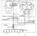
Das als Feldspritze ausgebildete landwirtschaftliche Spritzgerät zum Ausbringen von Spritzmitteln weist einen Vorratstank 1 auf, in dem sich die Trägerflüssigkeit, vornehmlich Wasser befindet. Von dem Vorratstank 1 führt eine Saugleitung 2 zu einer von einer Kraftquelle angetriebenen Pumpe 3. Die Ausgangsleitung 4 der Pumpe 3 führt zu der als Spritzdruckregler 5 ausgebildeten Dosierarmatur. Von dem Spritzdruckregler 5 führt eine Rücklaufleitung 6 in den Vorratstank 1 zurück. Über die Dosierarmatur wird die Fördermenge, die über die Spritzdüsen 7 des Spritzgestänges ausgebracht wird, eingestellt. Der überschüssige Trägerflüssigkeitsvolumenstrom wird über die Rücklaufleitung 6 in Vorratstank 1 zurück geleitet. Die Dosierarmatur 5, welches beispielsweise als 3-Wegeventil ausgebildet ist, ist im geschlossenen Druckregelkreis angeordnet, um in allen Betriebssituationen den optimalen Arbeitspunkt der Düsen 7 im Hinblick auf Spritzkegel und Tropfengröße zu gewährleisten.Trained as a sprayer agricultural sprayer for spreading sprays has a
Die von der Dosierarmatur 5 kommende Trägerflüssigkeitsleitung 8 verzweigt sich an der Stelle 9, die sich in der Nähe des Spritzgestänges befindet in einzelne Teilbreitenleitungen 10, die jeweils zu einer Teilbreite des Spritzgestänges und der dort angeordneten Spritzdüsen 7 führt. Hinter der Verzweigung 9 der Hauptträgerflüssigkeitsdruckleitung 8 ist in jeder Teilbreitenleitung 10 ein Teilbreitenventil 11 angeordnet. -Hinter dem Teilbreitenventil 11 ist in jeder Teilbreite eine Mischkammer 12 im Bereich des Spritzgestänges angeordnet. Von dieser Mischkammer 12 aus führt jede Teilbreitenleitung 10 zu den einzelnen an dem Spritzgestänge angeordneten Spritzdüsen. Diesen Spritzdüsen 7 kann ein Düsenventil 13 zugeordnet sein, über welche die Flüssigkeitszufuhr zu jeder Spritzdüse 7 separat absperrbar ist.The
Jedem auszubringendem Wirkstoffmittel 14 ist eine eigene Dosierpumpe 15, 16 zugeordnet, die jeweils von einem Motor 17 angetrieben wird. Die Wirkstoffmittelpumpen 15, 16 sind als einstellbare Pumpen ausgebildet und können im Ausführungsbeispiel mittels eines manuellen Verstellmechanismus von Hand eingestellt werden. Von der von der Trägerflüssigkeitspumpe 3 kommenden Druckleitung 4 zweigt vor dem Dosierventil 5 an der Verzweigstelle 18 eine Bypassleitung 19 ab. Diese unter Druck stehende und mit Trägerflüssigkeit gefüllte Bypassleitung 19 führt zu dem als wasserhydraulischen Motor ausgebildeten Antriebsmotor 17 für den Antrieb der Wirkstoffmittelpumpen 15, 16. Somit ist ein volumenstrom-proportionaler Antrieb für den wasserhydraulischen Motor 17 in der Trägerflüssigkeit führenden Bypassleitung 19 eingebaut, dessen Abtrieb gleichzeitig die beiden Wirkstoffmittelpumpen 15, 16 mit manueller Verstellung antreibt. Es können aber auch mit gleichem Resultat Elektromotoren oder ölhydraulische Motoren verwendet werden, die von einem Trägerflüssigkeitsvolumenstromsensor geführt werden.Each
Über den Handverstellungsmechanismus der Wirkstoffmittelpumpen 15, 16 wird vor Arbeitsbeginn die Aufwandmenge des Wirkstoffmittels fest eingestellt. Die während der Anwendung veränderlichen Parameter, wie Fahrgeschwindigkeit und Teilbreiten- bzw. Einfeldüsenschaltung und im Falle der teilfächendifferenzierten Bewirtschaftung - der örtliche Bedarf bewirken über die Steuerung 25 eine Verstellung der Proportionaleblende 24 und damit eine Anpassung des Volumenstroms der Wirkstoffpumpen 15, 16.About the manual adjustment mechanism of the active agent pumps 15, 16, the rate of application of the active agent is set before starting work. The variable during the application parameters such as driving speed and Teilbäch- or Einfeldüsschaltung and in the case of Teilfächendifferenzierten management - the local needs cause via the
In die unter Druck stehende Bypassleitung münden vor dem Antriebsmotor 17 die jeweils die von den Wirkstoffmittelpumpen 15, 16 kommende Wirkstoffmittelleitungen 20, 21 über eine Einschleusstelle 22 ein. An dieser Stelle 22 erfolgt die Vormischung bzw. Vorverdünnung der jeweiligen Wirkstoffmittel mit der sich in der Bypassleitung 19 befindenden und unter Druck stehenden Trägerflüssigkeit, hier Wasser. Durch die Durchleitung der Trägerflüssigkeit in der Bypassleitung 19 und der eingeschleusten Wirkstoffmitteln in den Leitungen 20 und 21 über die weiterführende Bypassleitung 19'durch den Antriebsmotor 17 werden diese in dem Antriebsmotor gut miteinander vermischt. Hinter dem Antriebsmotor 17 teilt sich die Bypassleitung 19' über ein Zweigleitungsstück 23 jeweils in die zu den in den Teilbreiten-Trägerflüssigkeitsleitungen 10 angeordneten Mischkamnfern 12 führenden Teilbypassleitungen 19" auf. In jeder Teilbreitenbypassleitung 19" ist ein einstellbares Ventil 24, im Ausführungsbeispiel eine einstellbare Proportionalblende angeordnet. In dem als Bypassleitung 19, 19', 19", ausgebildeten Nebenstrom wird das Wirkstoffmittel zunächst zu einer Vormischung aufbereitet und dann in einer Mischkammer 12 der Teilbreitenleitungen 10 mit der Trägerflüssigkeit zur endgültigen Spritzbrühe vermischt. Die Vormischung weist eine Wirkstoffmittelkonzentration auf, die an den Verstellpumpen 15, 16 einstellbar und proportional zu den Wirkstoffmittelaufwendungen sind. Die Verstellpumpen 15, 16 werden zur Erzeugung der Vormischung vor der Anwendung von Hand eingestellt, wahrend die jeweilige Proportionalblende 24 die veränderlichen Parameter während der Anwendung verarbeitet, in dem sie den Volumenstrom der Vormischung zur jeweiligen Teilbreite anpassen.In the pressurized bypass line open in front of the
Die Proportionalblenden 24 werden, wie dargestellt, über eine elektronische Steuerung 25 entsprechend angesteuert.As shown, the
Bei dieser Anordnung wird auch die besondere Stärke des Konstantendrucksystems für die Trägerflüssigkeit deutlich: trotz der durch die Verstellblenden 24 wechselnden Vormischungsvolumenströme über die als Nebenschluss dienenden Bypassleitungen 19, 19'19" sorgt die Druckregelung durch die Dosierarmatur 5 für die Trägerflüssigkeit ohne weitere steuerungstechnische Eingriffe für eine Verringerung des Trägerflüssigkeitsvolumenstroms über die Hauptleitung8 , so dass sich-schließlich die Teilströme zu dem für die Düsen 7 gewünschten optimalen Gesamtvolumenstrom addieren.In this arrangement, the particular strength of the constant pressure system for the carrier liquid is clear: despite the changing by the
In der in
Von der Steuerung 25 aus kann durch die Ansteuerung des jeweiligen Teilbreitenventils 11 jede Teilbereite entsprechend der jeweils erforderlichen Arbeitsbreite zu- oder abgeschaltet werden. Ebenfalls ist es, wie angedeutet, über die elektronische Steuerung 25 möglich, über die den einzelnen Düsen 7 zugeordneten Düsenventile 13 (von denen nur eins dargestellt ist) diese anzusteuern, so dass jede einzelne Düse 7 entsprechend abgesperrt oder zugeschaltet werden kann, so dass entsprechend der Spritzbreite einer Düse 7 die tatsächliche Ausbringbreite verändert werden kann.From the
Die Darstellung gemäß
Als Ergebnis entsteht ein System, dass jeder Teilbreite je eine Vormischung für jedes Wirkstoffmittel zuleitet, so dass an jeder Teilbreite jedes Wirkstoffmittel separat dosierbar ist. Da zudem durch die auf den Teilbreiten untergebrachten Mischkammern 12 sehr kleine Verzögerungen entstehen, ist mit diesem System die am weitesten gehende Form der teilflächenspezifischen Ausbringung möglich. Um zu gewährleisten, dass nach Möglichkeit nur geringe vorgemischte Wirkstoffmittelmengen bei Beendigung der Ausbringarbeit noch in den Leitungen 19', 19", 12 vorhanden sind, muss durch die Steuerung 25 sichergestellt werden, dass mit Kenntnis der Volumenströme und der Schlauchvolumina die Zudosierung der Wirkstoffmittel genau zu dem Zeitpunkt vor Ende der Anwendung gestoppt wird, dass die in den Schläuchen befindlichen Restmengen zur Behandlung der Restfläche genau ausreichen. Bildlich gesprochen schiebt die Trägerflüssigkeit die Spritzbrühen bzw. Vormischung sowohl in der Teilmischungsbypassleitung wie auch in den Teilbreiten vor sich her, bis die Leitung bis zur Spritzdüse 7 diesbezüglich leer sind. Voraussetzung dafür sind natürlich jeweils zumindest annähernd gleiche Schlauchvolumina in allen die Teilbreiten versorgenden Stränge.The result is a system that each sub-width each feeds a premix for each active ingredient, so that each active ingredient is metered separately at each section. In addition, since 12 very small delays caused by the accommodated on the
Die Füllung funktioniert unter diesen Voraussetzungen nach dem gleichen Prinzip umgekehrt: die leeren bzw. mit Trägerflüssigkeit der letzten Anwendung gefüllten Leitungen in die Peripherie werden zunächst durch nachdrückende Spritzbrühe bzw. Vormischungen gefüllt, mit Kenntnis der Volumenströme der Schlauchvolumina genau so lange, dass als Ergebnis vor den Düsen die neue Spritzbrühe ansteht.The filling works under these conditions on the same principle vice versa: the empty or filled with carrier liquid of the last application lines to the periphery are first filled by nachdrückende spray mixture or premixes, with knowledge of the volume flows of the tube volumes just as long that as a result the nozzles are filled with the new spray mixture.
Claims (11)
- Spraying device for discharging liquids, in particular for agricultural purposes, having a spray beam arrangement which is assigned to a vehicle and is equipped with spray nozzles (7) and has at least one liquid line which runs transversally with respect to the direction of travel and is provided with spray nozzles (7) at intervals, wherein the liquid can be fed in an adjustable quantity to the spray nozzles (7) via the at least one liquid line (4) in each case by at least one pump (3) which delivers the carrier liquid and produces the spray pressure and at least one pump (15, 16, 17) which delivers at least one active substance and feeds same into the carrier liquid and at least one point in a metered manner, wherein at least one active substance can be fed, first of all for pre-dilution, into at least one pressurized bypass line (19, 19') of the carrier liquid by means of at least one pump (15, 16, 17), wherein the at least one bypass line (19', 19") which is prediluted with the carrier liquid and contains pressurized active substances opens into the at least one carrier liquid line (10) leading to the spray nozzles (7), wherein a mixing chamber (12) is arranged in the carrier liquid line (10) at the point at which the bypass line (19") opens into the carrier liquid line (10); characterized in that the pressurized bypass line (19, 19') branches off from the liquid line (4), as seen in the flow direction, behind the pump (3) delivering the carrier liquid and producing the spray pressure and also opens behind the said pump into the at least one carrier liquid line (10) leading to the spray nozzles (7).
- Spraying device according to Claim 1, characterized in that a device (24) with which the flow quantity in the bypass line (19', 19") can be adjusted is arranged in each bypass line (19, 19').
- Spraying device according to Claim 2, characterized in that the device for adjusting the flow quantity is an adjustable flow valve (24).
- Spraying device according to one or more of the preceding claims, characterized in that a power motor (17) which is driven by the liquid flow (19') flowing in the bypass line (19') is arranged in the bypass line (19'), in that the power motor (17) drives at least one pump (15, 16) delivering active substance and feeding same into the bypass line (19, 19').
- Spraying device according to one or more of the Claims 1 to 4, characterized in that the pump (15, 16) is driven by an electric motor, in that a flow sensor is arranged in the bypass line (19', 19"), and in that the rotational speed of the motor and therefore the pumping quantity of the associated pump can be set with the aid of the sensor.
- Spraying device according to one or more of the preceding Claims 1 to 4, characterized in that the pump delivering an active substance and feeding same into the bypass line (19, 19') operates in such a manner that the volumetric flow of active substance delivered by the pump is proportional to the volumetric flow of carrier liquid flowing in the bypass line (19', 19").
- Spraying device according to one or more of the preceding claims, characterized in that an active substance line (20) coming into the in each case from the pump (15, 16) delivering active substance opens into the bypass line (19, 19') in front of or behind the drive motor (17).
- Spraying device according to one of the preceding claims, characterized in that the bypass line (19) is divided behind the drive motor or the flow sensor and the feeding point of the at least one active substance line into the bypass line (19) between a number of partial bypass lines (19"), the number corresponding to the number of partial widths (10) of the spray beam arrangement, in that the carrier liquid line (10) is divided before each partial width of the spray beam arrangement into associated partial width lines (10), in that in each case one partial bypass line (19") opens into a mixing chamber (12) arranged in the partial width carrier liquid line (10), and in that an adjustable flow valve (24) is arranged in each partial width bypass line (19").
- Spraying device according to one or more of the preceding claims, characterized in that the flow valves (24) arranged in the partial width bypass line (19") are designed as adjustable restrictors.
- Spraying device according to one or more of the preceding claims, characterized in that the flow valves (24) arranged in the partial width bypass line (19") are designed as proportional restrictors or proportional throttles.
- Spraying device according to one or more of the preceding claims, characterized in that the flow valves (24) arranged in the bypass lines (19, 19', 19") or in the partial width bypass lines (19") are adjustable via an electronic device (25) depending on the pressure prevailing in the carrier liquid line and/or depending on a travel or driving speed signal of the spraying device moving over the soil surface and/or depending on the respectively current requirement of active substances based on the cultivated area of soil.
Applications Claiming Priority (1)
| Application Number | Priority Date | Filing Date | Title |
|---|---|---|---|
| DE200610059193 DE102006059193A1 (en) | 2006-12-15 | 2006-12-15 | spraying device |
Publications (2)
| Publication Number | Publication Date |
|---|---|
| EP1932423A1 EP1932423A1 (en) | 2008-06-18 |
| EP1932423B1 true EP1932423B1 (en) | 2017-04-05 |
Family
ID=39135172
Family Applications (1)
| Application Number | Title | Priority Date | Filing Date |
|---|---|---|---|
| EP07023621.1A Active EP1932423B1 (en) | 2006-12-15 | 2007-12-06 | Spraying device |
Country Status (2)
| Country | Link |
|---|---|
| EP (1) | EP1932423B1 (en) |
| DE (1) | DE102006059193A1 (en) |
Families Citing this family (12)
| Publication number | Priority date | Publication date | Assignee | Title |
|---|---|---|---|---|
| DE102015119084A1 (en) * | 2015-11-06 | 2017-05-11 | Amazonen-Werke H. Dreyer Gmbh & Co. Kg | Spraying device for spraying liquids and method for spraying liquids |
| DE102017100778A1 (en) * | 2017-01-17 | 2018-07-19 | Amazonen-Werke H. Dreyer Gmbh & Co. Kg | Method, fluid circuit and spraying device for applying a spray liquid on an agricultural surface |
| DE102017214783A1 (en) | 2017-08-23 | 2019-02-28 | Robert Bosch Gmbh | Agricultural dispensing unit for dispensing a liquid |
| DE102017220028A1 (en) | 2017-11-10 | 2019-05-16 | Robert Bosch Gmbh | Spraying device and method |
| DE102017220030A1 (en) | 2017-11-10 | 2019-05-16 | Robert Bosch Gmbh | spraying device |
| DE102017220016A1 (en) | 2017-11-10 | 2019-05-16 | Robert Bosch Gmbh | Agricultural sprayer |
| DE102017126350A1 (en) | 2017-11-10 | 2019-05-16 | Amazonen-Werke H. Dreyer Gmbh & Co. Kg | Active ingredient supply system for an agricultural sprayer |
| DE102018102586A1 (en) | 2018-02-06 | 2019-08-08 | Amazonen-Werke H. Dreyer Gmbh & Co. Kg | Method for dispensing a spray liquid |
| DE102018203789A1 (en) * | 2018-03-13 | 2019-09-19 | Robert Bosch Gmbh | Agricultural sprayer |
| DE102020128770A1 (en) | 2020-11-02 | 2022-05-05 | Horsch Leeb Application Systems Gmbh | Agricultural field sprayer and spraying device for an agricultural field sprayer |
| DE102020128771A1 (en) * | 2020-11-02 | 2022-05-05 | Horsch Leeb Application Systems Gmbh | Agricultural field sprayer and spraying device for an agricultural field sprayer |
| CN112806341B (en) * | 2021-02-25 | 2023-05-09 | 吉林大学 | Orchard targeting spraying control system and method based on laminar layer |
Family Cites Families (4)
| Publication number | Priority date | Publication date | Assignee | Title |
|---|---|---|---|---|
| GB2048091A (en) * | 1979-02-13 | 1980-12-10 | Agmet Instr | Spraying Equipment |
| US5310113A (en) * | 1992-12-01 | 1994-05-10 | Cowgur Bruce E | Sprayer control system and method for using same |
| DE102004047585A1 (en) | 2004-09-23 | 2006-03-30 | Lechler Gmbh | Active ingredient supply system for a device for spraying agricultural liquids comprises an active ingredient container, a dosing pump for injecting the active ingredient and an active ingredient feed line |
| DE102005036603A1 (en) * | 2005-08-01 | 2007-02-08 | Amazonen-Werke H. Dreyer Gmbh & Co. Kg | Agricultural sprayer |
-
2006
- 2006-12-15 DE DE200610059193 patent/DE102006059193A1/en not_active Withdrawn
-
2007
- 2007-12-06 EP EP07023621.1A patent/EP1932423B1/en active Active
Non-Patent Citations (1)
| Title |
|---|
| None * |
Also Published As
| Publication number | Publication date |
|---|---|
| EP1932423A1 (en) | 2008-06-18 |
| DE102006059193A1 (en) | 2008-06-19 |
Similar Documents
| Publication | Publication Date | Title |
|---|---|---|
| EP1932423B1 (en) | Spraying device | |
| DE3908963C2 (en) | Device for applying plant treatment products with speed-dependent direct feed | |
| DE102009026234B4 (en) | spray device | |
| DE10233468A1 (en) | Device and method for feeding a liquid paint into a polymer melt | |
| EP3167712B1 (en) | Spray device for spraying liquids, and method for the spraying of a liquid | |
| EP2790497B1 (en) | System and method for applying liquid mixtures | |
| EP3332639B1 (en) | Agricultural field spraying device | |
| EP1932424B1 (en) | Spraying device | |
| WO2012152758A1 (en) | Agricultural field sprayer | |
| EP0385926B1 (en) | Apparatus for distributing plant-protecting agents | |
| DE102010023380B4 (en) | Refillable and self-dosing system for pesticides with integrated hydraulically driven dosing pump | |
| EP3645170A1 (en) | Discharge unit for discharging a final liquid having a defined mixing ratio | |
| EP3991556A1 (en) | Agricultural sprayer and spraying device for agricultural sprayer | |
| DE102010055019A1 (en) | Device for the intermittent application of a liquid to pasty medium on an application surface | |
| EP1902774A1 (en) | Mixing device, spraying device for pest management and method for operating a spraying device | |
| EP3871499A1 (en) | Spraying device for discharging spray liquid, agricultural field sprayer and method for operating a spraying device | |
| EP3311663A1 (en) | Spraying device for applying a liquid to be sprayed on an agricultural area | |
| EP3430901A1 (en) | Spraying system for agricultural field sprayers and method for regulating the pressure in at least one supply line circuit of an injection system for agricultural field sprayers | |
| DE2315434C3 (en) | Device for dispensing a liquid | |
| DE19533470A1 (en) | Agricultural field spray for dosed spraying of liquid fertiliser | |
| DE102020128770A1 (en) | Agricultural field sprayer and spraying device for an agricultural field sprayer | |
| DE102020128773A1 (en) | Agricultural field sprayer and spraying device for an agricultural field sprayer | |
| DE2315434B2 (en) | DEVICE FOR DISPENSING A LIQUID | |
| DE102007038636A1 (en) | Spraying device for bringing out liquid in agricultural purpose, has mixing container connected over line, with which dosing pump feeds before-diluted ingredient agent into carrier liquid, before production of liquid | |
| WO2008095527A1 (en) | Spraying device for delivering liquids |
Legal Events
| Date | Code | Title | Description |
|---|---|---|---|
| PUAI | Public reference made under article 153(3) epc to a published international application that has entered the european phase |
Free format text: ORIGINAL CODE: 0009012 |
|
| AK | Designated contracting states |
Kind code of ref document: A1 Designated state(s): AT BE BG CH CY CZ DE DK EE ES FI FR GB GR HU IE IS IT LI LT LU LV MC MT NL PL PT RO SE SI SK TR |
|
| AX | Request for extension of the european patent |
Extension state: AL BA HR MK RS |
|
| 17P | Request for examination filed |
Effective date: 20081217 |
|
| 17Q | First examination report despatched |
Effective date: 20090119 |
|
| AKX | Designation fees paid |
Designated state(s): AT BE BG CH CY CZ DE DK EE ES FI FR GB GR HU IE IS IT LI LT LU LV MC MT NL PL PT RO SE SI SK TR |
|
| GRAP | Despatch of communication of intention to grant a patent |
Free format text: ORIGINAL CODE: EPIDOSNIGR1 |
|
| INTG | Intention to grant announced |
Effective date: 20161221 |
|
| GRAS | Grant fee paid |
Free format text: ORIGINAL CODE: EPIDOSNIGR3 |
|
| GRAA | (expected) grant |
Free format text: ORIGINAL CODE: 0009210 |
|
| AK | Designated contracting states |
Kind code of ref document: B1 Designated state(s): AT BE BG CH CY CZ DE DK EE ES FI FR GB GR HU IE IS IT LI LT LU LV MC MT NL PL PT RO SE SI SK TR |
|
| REG | Reference to a national code |
Ref country code: GB Ref legal event code: FG4D Free format text: NOT ENGLISH |
|
| REG | Reference to a national code |
Ref country code: CH Ref legal event code: EP |
|
| REG | Reference to a national code |
Ref country code: AT Ref legal event code: REF Ref document number: 880891 Country of ref document: AT Kind code of ref document: T Effective date: 20170415 |
|
| REG | Reference to a national code |
Ref country code: IE Ref legal event code: FG4D Free format text: LANGUAGE OF EP DOCUMENT: GERMAN |
|
| REG | Reference to a national code |
Ref country code: DE Ref legal event code: R096 Ref document number: 502007015555 Country of ref document: DE |
|
| REG | Reference to a national code |
Ref country code: NL Ref legal event code: FP |
|
| REG | Reference to a national code |
Ref country code: LT Ref legal event code: MG4D |
|
| PG25 | Lapsed in a contracting state [announced via postgrant information from national office to epo] |
Ref country code: ES Free format text: LAPSE BECAUSE OF FAILURE TO SUBMIT A TRANSLATION OF THE DESCRIPTION OR TO PAY THE FEE WITHIN THE PRESCRIBED TIME-LIMIT Effective date: 20170405 Ref country code: FI Free format text: LAPSE BECAUSE OF FAILURE TO SUBMIT A TRANSLATION OF THE DESCRIPTION OR TO PAY THE FEE WITHIN THE PRESCRIBED TIME-LIMIT Effective date: 20170405 Ref country code: GR Free format text: LAPSE BECAUSE OF FAILURE TO SUBMIT A TRANSLATION OF THE DESCRIPTION OR TO PAY THE FEE WITHIN THE PRESCRIBED TIME-LIMIT Effective date: 20170706 Ref country code: LT Free format text: LAPSE BECAUSE OF FAILURE TO SUBMIT A TRANSLATION OF THE DESCRIPTION OR TO PAY THE FEE WITHIN THE PRESCRIBED TIME-LIMIT Effective date: 20170405 |
|
| REG | Reference to a national code |
Ref country code: FR Ref legal event code: PLFP Year of fee payment: 11 |
|
| PG25 | Lapsed in a contracting state [announced via postgrant information from national office to epo] |
Ref country code: IS Free format text: LAPSE BECAUSE OF FAILURE TO SUBMIT A TRANSLATION OF THE DESCRIPTION OR TO PAY THE FEE WITHIN THE PRESCRIBED TIME-LIMIT Effective date: 20170805 Ref country code: PL Free format text: LAPSE BECAUSE OF FAILURE TO SUBMIT A TRANSLATION OF THE DESCRIPTION OR TO PAY THE FEE WITHIN THE PRESCRIBED TIME-LIMIT Effective date: 20170405 Ref country code: BG Free format text: LAPSE BECAUSE OF FAILURE TO SUBMIT A TRANSLATION OF THE DESCRIPTION OR TO PAY THE FEE WITHIN THE PRESCRIBED TIME-LIMIT Effective date: 20170705 Ref country code: LV Free format text: LAPSE BECAUSE OF FAILURE TO SUBMIT A TRANSLATION OF THE DESCRIPTION OR TO PAY THE FEE WITHIN THE PRESCRIBED TIME-LIMIT Effective date: 20170405 Ref country code: SE Free format text: LAPSE BECAUSE OF FAILURE TO SUBMIT A TRANSLATION OF THE DESCRIPTION OR TO PAY THE FEE WITHIN THE PRESCRIBED TIME-LIMIT Effective date: 20170405 |
|
| REG | Reference to a national code |
Ref country code: DE Ref legal event code: R097 Ref document number: 502007015555 Country of ref document: DE |
|
| PG25 | Lapsed in a contracting state [announced via postgrant information from national office to epo] |
Ref country code: RO Free format text: LAPSE BECAUSE OF FAILURE TO SUBMIT A TRANSLATION OF THE DESCRIPTION OR TO PAY THE FEE WITHIN THE PRESCRIBED TIME-LIMIT Effective date: 20170405 Ref country code: CZ Free format text: LAPSE BECAUSE OF FAILURE TO SUBMIT A TRANSLATION OF THE DESCRIPTION OR TO PAY THE FEE WITHIN THE PRESCRIBED TIME-LIMIT Effective date: 20170405 Ref country code: SK Free format text: LAPSE BECAUSE OF FAILURE TO SUBMIT A TRANSLATION OF THE DESCRIPTION OR TO PAY THE FEE WITHIN THE PRESCRIBED TIME-LIMIT Effective date: 20170405 Ref country code: DK Free format text: LAPSE BECAUSE OF FAILURE TO SUBMIT A TRANSLATION OF THE DESCRIPTION OR TO PAY THE FEE WITHIN THE PRESCRIBED TIME-LIMIT Effective date: 20170405 Ref country code: EE Free format text: LAPSE BECAUSE OF FAILURE TO SUBMIT A TRANSLATION OF THE DESCRIPTION OR TO PAY THE FEE WITHIN THE PRESCRIBED TIME-LIMIT Effective date: 20170405 |
|
| PLBE | No opposition filed within time limit |
Free format text: ORIGINAL CODE: 0009261 |
|
| STAA | Information on the status of an ep patent application or granted ep patent |
Free format text: STATUS: NO OPPOSITION FILED WITHIN TIME LIMIT |
|
| PG25 | Lapsed in a contracting state [announced via postgrant information from national office to epo] |
Ref country code: IT Free format text: LAPSE BECAUSE OF FAILURE TO SUBMIT A TRANSLATION OF THE DESCRIPTION OR TO PAY THE FEE WITHIN THE PRESCRIBED TIME-LIMIT Effective date: 20170405 |
|
| 26N | No opposition filed |
Effective date: 20180108 |
|
| PG25 | Lapsed in a contracting state [announced via postgrant information from national office to epo] |
Ref country code: SI Free format text: LAPSE BECAUSE OF FAILURE TO SUBMIT A TRANSLATION OF THE DESCRIPTION OR TO PAY THE FEE WITHIN THE PRESCRIBED TIME-LIMIT Effective date: 20170405 |
|
| REG | Reference to a national code |
Ref country code: CH Ref legal event code: PL |
|
| GBPC | Gb: european patent ceased through non-payment of renewal fee |
Effective date: 20171206 |
|
| REG | Reference to a national code |
Ref country code: IE Ref legal event code: MM4A |
|
| PG25 | Lapsed in a contracting state [announced via postgrant information from national office to epo] |
Ref country code: MT Free format text: LAPSE BECAUSE OF FAILURE TO SUBMIT A TRANSLATION OF THE DESCRIPTION OR TO PAY THE FEE WITHIN THE PRESCRIBED TIME-LIMIT Effective date: 20170405 Ref country code: LU Free format text: LAPSE BECAUSE OF NON-PAYMENT OF DUE FEES Effective date: 20171206 |
|
| REG | Reference to a national code |
Ref country code: BE Ref legal event code: MM Effective date: 20171231 |
|
| PG25 | Lapsed in a contracting state [announced via postgrant information from national office to epo] |
Ref country code: IE Free format text: LAPSE BECAUSE OF NON-PAYMENT OF DUE FEES Effective date: 20171206 |
|
| PG25 | Lapsed in a contracting state [announced via postgrant information from national office to epo] |
Ref country code: GB Free format text: LAPSE BECAUSE OF NON-PAYMENT OF DUE FEES Effective date: 20171206 Ref country code: BE Free format text: LAPSE BECAUSE OF NON-PAYMENT OF DUE FEES Effective date: 20171231 Ref country code: CH Free format text: LAPSE BECAUSE OF NON-PAYMENT OF DUE FEES Effective date: 20171231 Ref country code: LI Free format text: LAPSE BECAUSE OF NON-PAYMENT OF DUE FEES Effective date: 20171231 |
|
| REG | Reference to a national code |
Ref country code: AT Ref legal event code: MM01 Ref document number: 880891 Country of ref document: AT Kind code of ref document: T Effective date: 20171206 |
|
| PG25 | Lapsed in a contracting state [announced via postgrant information from national office to epo] |
Ref country code: AT Free format text: LAPSE BECAUSE OF NON-PAYMENT OF DUE FEES Effective date: 20171206 |
|
| PG25 | Lapsed in a contracting state [announced via postgrant information from national office to epo] |
Ref country code: MC Free format text: LAPSE BECAUSE OF FAILURE TO SUBMIT A TRANSLATION OF THE DESCRIPTION OR TO PAY THE FEE WITHIN THE PRESCRIBED TIME-LIMIT Effective date: 20170405 Ref country code: HU Free format text: LAPSE BECAUSE OF FAILURE TO SUBMIT A TRANSLATION OF THE DESCRIPTION OR TO PAY THE FEE WITHIN THE PRESCRIBED TIME-LIMIT; INVALID AB INITIO Effective date: 20071206 |
|
| PG25 | Lapsed in a contracting state [announced via postgrant information from national office to epo] |
Ref country code: CY Free format text: LAPSE BECAUSE OF NON-PAYMENT OF DUE FEES Effective date: 20170405 |
|
| PG25 | Lapsed in a contracting state [announced via postgrant information from national office to epo] |
Ref country code: TR Free format text: LAPSE BECAUSE OF FAILURE TO SUBMIT A TRANSLATION OF THE DESCRIPTION OR TO PAY THE FEE WITHIN THE PRESCRIBED TIME-LIMIT Effective date: 20170405 |
|
| PG25 | Lapsed in a contracting state [announced via postgrant information from national office to epo] |
Ref country code: PT Free format text: LAPSE BECAUSE OF FAILURE TO SUBMIT A TRANSLATION OF THE DESCRIPTION OR TO PAY THE FEE WITHIN THE PRESCRIBED TIME-LIMIT Effective date: 20170405 |
|
| REG | Reference to a national code |
Ref country code: DE Ref legal event code: R082 Ref document number: 502007015555 Country of ref document: DE Representative=s name: KILBURN & STRODE LLP, GB Ref country code: DE Ref legal event code: R082 Ref document number: 502007015555 Country of ref document: DE Representative=s name: KILBURN & STRODE LLP, NL Ref country code: DE Ref legal event code: R081 Ref document number: 502007015555 Country of ref document: DE Owner name: AMAZONEN-WERKE H. DREYER SE & CO. KG, DE Free format text: FORMER OWNER: AMAZONEN-WERKE H. DREYER GMBH & CO. KG, 49205 HASBERGEN, DE |
|
| REG | Reference to a national code |
Ref country code: DE Ref legal event code: R082 Ref document number: 502007015555 Country of ref document: DE Representative=s name: KILBURN & STRODE LLP, NL |
|
| P01 | Opt-out of the competence of the unified patent court (upc) registered |
Effective date: 20230523 |
|
| PGFP | Annual fee paid to national office [announced via postgrant information from national office to epo] |
Ref country code: NL Payment date: 20231016 Year of fee payment: 17 Ref country code: FR Payment date: 20230929 Year of fee payment: 17 |
|
| PGFP | Annual fee paid to national office [announced via postgrant information from national office to epo] |
Ref country code: DE Payment date: 20231010 Year of fee payment: 17 |