EP1932202B1 - Ceramic membranes with integral seals and support, and electrochemical cells and electrochemical cell stacks including the same - Google Patents
Ceramic membranes with integral seals and support, and electrochemical cells and electrochemical cell stacks including the same Download PDFInfo
- Publication number
- EP1932202B1 EP1932202B1 EP06803014.7A EP06803014A EP1932202B1 EP 1932202 B1 EP1932202 B1 EP 1932202B1 EP 06803014 A EP06803014 A EP 06803014A EP 1932202 B1 EP1932202 B1 EP 1932202B1
- Authority
- EP
- European Patent Office
- Prior art keywords
- porous electrode
- ceramic electrolyte
- ceramic
- electrode material
- electrolyte
- Prior art date
- Legal status (The legal status is an assumption and is not a legal conclusion. Google has not performed a legal analysis and makes no representation as to the accuracy of the status listed.)
- Not-in-force
Links
- 239000012528 membrane Substances 0.000 title claims description 63
- 239000000919 ceramic Substances 0.000 title claims description 45
- 239000003792 electrolyte Substances 0.000 claims description 104
- 239000007772 electrode material Substances 0.000 claims description 41
- 229910021525 ceramic electrolyte Inorganic materials 0.000 claims description 39
- 239000000463 material Substances 0.000 claims description 30
- 239000000203 mixture Substances 0.000 claims description 26
- 238000007789 sealing Methods 0.000 claims description 26
- 239000002001 electrolyte material Substances 0.000 claims description 20
- PXHVJJICTQNCMI-UHFFFAOYSA-N Nickel Chemical compound [Ni] PXHVJJICTQNCMI-UHFFFAOYSA-N 0.000 claims description 8
- 238000009792 diffusion process Methods 0.000 claims description 8
- 229910002076 stabilized zirconia Inorganic materials 0.000 claims description 7
- NFYLSJDPENHSBT-UHFFFAOYSA-N chromium(3+);lanthanum(3+);oxygen(2-) Chemical compound [O-2].[O-2].[O-2].[Cr+3].[La+3] NFYLSJDPENHSBT-UHFFFAOYSA-N 0.000 claims description 4
- 229910052759 nickel Inorganic materials 0.000 claims description 4
- 229910000416 bismuth oxide Inorganic materials 0.000 claims description 3
- 229910000420 cerium oxide Inorganic materials 0.000 claims description 3
- TYIXMATWDRGMPF-UHFFFAOYSA-N dibismuth;oxygen(2-) Chemical compound [O-2].[O-2].[O-2].[Bi+3].[Bi+3] TYIXMATWDRGMPF-UHFFFAOYSA-N 0.000 claims description 3
- 229910052746 lanthanum Inorganic materials 0.000 claims description 3
- FZLIPJUXYLNCLC-UHFFFAOYSA-N lanthanum atom Chemical compound [La] FZLIPJUXYLNCLC-UHFFFAOYSA-N 0.000 claims description 3
- RVTZCBVAJQQJTK-UHFFFAOYSA-N oxygen(2-);zirconium(4+) Chemical compound [O-2].[O-2].[Zr+4] RVTZCBVAJQQJTK-UHFFFAOYSA-N 0.000 claims description 3
- 229910001220 stainless steel Inorganic materials 0.000 claims description 3
- 229910000601 superalloy Inorganic materials 0.000 claims description 3
- 229910001928 zirconium oxide Inorganic materials 0.000 claims description 3
- VYZAMTAEIAYCRO-UHFFFAOYSA-N Chromium Chemical compound [Cr] VYZAMTAEIAYCRO-UHFFFAOYSA-N 0.000 claims description 2
- LNTHITQWFMADLM-UHFFFAOYSA-N gallic acid Chemical compound OC(=O)C1=CC(O)=C(O)C(O)=C1 LNTHITQWFMADLM-UHFFFAOYSA-N 0.000 claims 1
- BMMGVYCKOGBVEV-UHFFFAOYSA-N oxo(oxoceriooxy)cerium Chemical compound [Ce]=O.O=[Ce]=O BMMGVYCKOGBVEV-UHFFFAOYSA-N 0.000 claims 1
- 239000010410 layer Substances 0.000 description 195
- 239000000446 fuel Substances 0.000 description 21
- 238000000034 method Methods 0.000 description 21
- 238000005520 cutting process Methods 0.000 description 13
- 239000000976 ink Substances 0.000 description 12
- 230000008569 process Effects 0.000 description 11
- 238000005245 sintering Methods 0.000 description 11
- 239000002131 composite material Substances 0.000 description 10
- 238000010345 tape casting Methods 0.000 description 10
- 238000004519 manufacturing process Methods 0.000 description 9
- 238000003475 lamination Methods 0.000 description 8
- 239000000843 powder Substances 0.000 description 8
- 230000008901 benefit Effects 0.000 description 7
- 239000007789 gas Substances 0.000 description 7
- 238000007650 screen-printing Methods 0.000 description 7
- 239000007787 solid Substances 0.000 description 7
- 238000002360 preparation method Methods 0.000 description 6
- 238000012545 processing Methods 0.000 description 6
- 229910010293 ceramic material Inorganic materials 0.000 description 5
- 238000000151 deposition Methods 0.000 description 5
- 238000010304 firing Methods 0.000 description 5
- 229910052751 metal Inorganic materials 0.000 description 5
- 239000002184 metal Substances 0.000 description 5
- BQENXCOZCUHKRE-UHFFFAOYSA-N [La+3].[La+3].[O-][Mn]([O-])=O.[O-][Mn]([O-])=O.[O-][Mn]([O-])=O Chemical compound [La+3].[La+3].[O-][Mn]([O-])=O.[O-][Mn]([O-])=O.[O-][Mn]([O-])=O BQENXCOZCUHKRE-UHFFFAOYSA-N 0.000 description 4
- 239000011230 binding agent Substances 0.000 description 4
- 238000005266 casting Methods 0.000 description 4
- 238000003698 laser cutting Methods 0.000 description 4
- BASFCYQUMIYNBI-UHFFFAOYSA-N platinum Chemical compound [Pt] BASFCYQUMIYNBI-UHFFFAOYSA-N 0.000 description 4
- IJGRMHOSHXDMSA-UHFFFAOYSA-N Atomic nitrogen Chemical compound N#N IJGRMHOSHXDMSA-UHFFFAOYSA-N 0.000 description 3
- PNEYBMLMFCGWSK-UHFFFAOYSA-N aluminium oxide Inorganic materials [O-2].[O-2].[O-2].[Al+3].[Al+3] PNEYBMLMFCGWSK-UHFFFAOYSA-N 0.000 description 3
- 239000010405 anode material Substances 0.000 description 3
- QVGXLLKOCUKJST-UHFFFAOYSA-N atomic oxygen Chemical compound [O] QVGXLLKOCUKJST-UHFFFAOYSA-N 0.000 description 3
- 239000010406 cathode material Substances 0.000 description 3
- 238000006243 chemical reaction Methods 0.000 description 3
- 239000004020 conductor Substances 0.000 description 3
- 238000013461 design Methods 0.000 description 3
- 230000009477 glass transition Effects 0.000 description 3
- 238000010438 heat treatment Methods 0.000 description 3
- 239000010416 ion conductor Substances 0.000 description 3
- 238000010030 laminating Methods 0.000 description 3
- 239000007769 metal material Substances 0.000 description 3
- 150000002739 metals Chemical class 0.000 description 3
- 239000001301 oxygen Substances 0.000 description 3
- 229910052760 oxygen Inorganic materials 0.000 description 3
- 239000011148 porous material Substances 0.000 description 3
- 238000007639 printing Methods 0.000 description 3
- 238000011946 reduction process Methods 0.000 description 3
- 229910001233 yttria-stabilized zirconia Inorganic materials 0.000 description 3
- BQCADISMDOOEFD-UHFFFAOYSA-N Silver Chemical compound [Ag] BQCADISMDOOEFD-UHFFFAOYSA-N 0.000 description 2
- 230000003197 catalytic effect Effects 0.000 description 2
- DRVWBEJJZZTIGJ-UHFFFAOYSA-N cerium(3+);oxygen(2-) Chemical class [O-2].[O-2].[O-2].[Ce+3].[Ce+3] DRVWBEJJZZTIGJ-UHFFFAOYSA-N 0.000 description 2
- 239000011195 cermet Substances 0.000 description 2
- 230000000052 comparative effect Effects 0.000 description 2
- 238000007796 conventional method Methods 0.000 description 2
- 230000008021 deposition Effects 0.000 description 2
- 238000009826 distribution Methods 0.000 description 2
- 238000001035 drying Methods 0.000 description 2
- 238000005516 engineering process Methods 0.000 description 2
- 238000001125 extrusion Methods 0.000 description 2
- 238000010100 freeform fabrication Methods 0.000 description 2
- 229910021526 gadolinium-doped ceria Inorganic materials 0.000 description 2
- 230000003993 interaction Effects 0.000 description 2
- 239000011229 interlayer Substances 0.000 description 2
- 229910052747 lanthanoid Inorganic materials 0.000 description 2
- 150000002602 lanthanoids Chemical class 0.000 description 2
- 229910000480 nickel oxide Inorganic materials 0.000 description 2
- 239000011224 oxide ceramic Substances 0.000 description 2
- GNRSAWUEBMWBQH-UHFFFAOYSA-N oxonickel Chemical compound [Ni]=O GNRSAWUEBMWBQH-UHFFFAOYSA-N 0.000 description 2
- 238000012856 packing Methods 0.000 description 2
- 229910002077 partially stabilized zirconia Inorganic materials 0.000 description 2
- 229910052697 platinum Inorganic materials 0.000 description 2
- 229920000642 polymer Polymers 0.000 description 2
- 238000003825 pressing Methods 0.000 description 2
- 238000004080 punching Methods 0.000 description 2
- 230000009467 reduction Effects 0.000 description 2
- 238000011160 research Methods 0.000 description 2
- 238000000926 separation method Methods 0.000 description 2
- 229910052709 silver Inorganic materials 0.000 description 2
- 239000004332 silver Substances 0.000 description 2
- 238000007569 slipcasting Methods 0.000 description 2
- 239000002002 slurry Substances 0.000 description 2
- 238000009718 spray deposition Methods 0.000 description 2
- 238000012360 testing method Methods 0.000 description 2
- 239000011800 void material Substances 0.000 description 2
- 229910000859 α-Fe Inorganic materials 0.000 description 2
- 229920002799 BoPET Polymers 0.000 description 1
- WSNMPAVSZJSIMT-UHFFFAOYSA-N COc1c(C)c2COC(=O)c2c(O)c1CC(O)C1(C)CCC(=O)O1 Chemical compound COc1c(C)c2COC(=O)c2c(O)c1CC(O)C1(C)CCC(=O)O1 WSNMPAVSZJSIMT-UHFFFAOYSA-N 0.000 description 1
- 239000005041 Mylar™ Substances 0.000 description 1
- 239000000443 aerosol Substances 0.000 description 1
- 229910052782 aluminium Inorganic materials 0.000 description 1
- XAGFODPZIPBFFR-UHFFFAOYSA-N aluminium Chemical compound [Al] XAGFODPZIPBFFR-UHFFFAOYSA-N 0.000 description 1
- 238000013459 approach Methods 0.000 description 1
- 230000004888 barrier function Effects 0.000 description 1
- 230000015572 biosynthetic process Effects 0.000 description 1
- 238000003490 calendering Methods 0.000 description 1
- CETPSERCERDGAM-UHFFFAOYSA-N ceric oxide Chemical compound O=[Ce]=O CETPSERCERDGAM-UHFFFAOYSA-N 0.000 description 1
- 229910000422 cerium(IV) oxide Inorganic materials 0.000 description 1
- 239000011248 coating agent Substances 0.000 description 1
- 238000000576 coating method Methods 0.000 description 1
- 230000000295 complement effect Effects 0.000 description 1
- 150000001875 compounds Chemical class 0.000 description 1
- 238000005336 cracking Methods 0.000 description 1
- 230000007547 defect Effects 0.000 description 1
- 230000002939 deleterious effect Effects 0.000 description 1
- 238000010790 dilution Methods 0.000 description 1
- 239000012895 dilution Substances 0.000 description 1
- 229910001873 dinitrogen Inorganic materials 0.000 description 1
- 238000003487 electrochemical reaction Methods 0.000 description 1
- 239000011262 electrochemically active material Substances 0.000 description 1
- 238000009472 formulation Methods 0.000 description 1
- 239000001257 hydrogen Substances 0.000 description 1
- 229910052739 hydrogen Inorganic materials 0.000 description 1
- 125000004435 hydrogen atom Chemical group [H]* 0.000 description 1
- 238000005259 measurement Methods 0.000 description 1
- 229910002119 nickel–yttria stabilized zirconia Inorganic materials 0.000 description 1
- 229910052757 nitrogen Inorganic materials 0.000 description 1
- 230000001590 oxidative effect Effects 0.000 description 1
- 239000003973 paint Substances 0.000 description 1
- 239000002245 particle Substances 0.000 description 1
- 229920006395 saturated elastomer Polymers 0.000 description 1
- 239000002356 single layer Substances 0.000 description 1
- 238000007592 spray painting technique Methods 0.000 description 1
- 238000005507 spraying Methods 0.000 description 1
- 239000000126 substance Substances 0.000 description 1
- 239000010409 thin film Substances 0.000 description 1
- 238000010023 transfer printing Methods 0.000 description 1
Images


Classifications
-
- H—ELECTRICITY
- H01—ELECTRIC ELEMENTS
- H01M—PROCESSES OR MEANS, e.g. BATTERIES, FOR THE DIRECT CONVERSION OF CHEMICAL ENERGY INTO ELECTRICAL ENERGY
- H01M8/00—Fuel cells; Manufacture thereof
- H01M8/10—Fuel cells with solid electrolytes
- H01M8/12—Fuel cells with solid electrolytes operating at high temperature, e.g. with stabilised ZrO2 electrolyte
- H01M8/1213—Fuel cells with solid electrolytes operating at high temperature, e.g. with stabilised ZrO2 electrolyte characterised by the electrode/electrolyte combination or the supporting material
- H01M8/1226—Fuel cells with solid electrolytes operating at high temperature, e.g. with stabilised ZrO2 electrolyte characterised by the electrode/electrolyte combination or the supporting material characterised by the supporting layer
-
- H—ELECTRICITY
- H01—ELECTRIC ELEMENTS
- H01M—PROCESSES OR MEANS, e.g. BATTERIES, FOR THE DIRECT CONVERSION OF CHEMICAL ENERGY INTO ELECTRICAL ENERGY
- H01M8/00—Fuel cells; Manufacture thereof
- H01M8/10—Fuel cells with solid electrolytes
- H01M8/12—Fuel cells with solid electrolytes operating at high temperature, e.g. with stabilised ZrO2 electrolyte
-
- H—ELECTRICITY
- H01—ELECTRIC ELEMENTS
- H01M—PROCESSES OR MEANS, e.g. BATTERIES, FOR THE DIRECT CONVERSION OF CHEMICAL ENERGY INTO ELECTRICAL ENERGY
- H01M4/00—Electrodes
- H01M4/86—Inert electrodes with catalytic activity, e.g. for fuel cells
- H01M4/90—Selection of catalytic material
- H01M4/9016—Oxides, hydroxides or oxygenated metallic salts
- H01M4/9025—Oxides specially used in fuel cell operating at high temperature, e.g. SOFC
- H01M4/9033—Complex oxides, optionally doped, of the type M1MeO3, M1 being an alkaline earth metal or a rare earth, Me being a metal, e.g. perovskites
-
- H—ELECTRICITY
- H01—ELECTRIC ELEMENTS
- H01M—PROCESSES OR MEANS, e.g. BATTERIES, FOR THE DIRECT CONVERSION OF CHEMICAL ENERGY INTO ELECTRICAL ENERGY
- H01M8/00—Fuel cells; Manufacture thereof
- H01M8/02—Details
-
- H—ELECTRICITY
- H01—ELECTRIC ELEMENTS
- H01M—PROCESSES OR MEANS, e.g. BATTERIES, FOR THE DIRECT CONVERSION OF CHEMICAL ENERGY INTO ELECTRICAL ENERGY
- H01M8/00—Fuel cells; Manufacture thereof
- H01M8/02—Details
- H01M8/0271—Sealing or supporting means around electrodes, matrices or membranes
- H01M8/028—Sealing means characterised by their material
- H01M8/0282—Inorganic material
-
- H—ELECTRICITY
- H01—ELECTRIC ELEMENTS
- H01M—PROCESSES OR MEANS, e.g. BATTERIES, FOR THE DIRECT CONVERSION OF CHEMICAL ENERGY INTO ELECTRICAL ENERGY
- H01M8/00—Fuel cells; Manufacture thereof
- H01M8/24—Grouping of fuel cells, e.g. stacking of fuel cells
-
- H—ELECTRICITY
- H01—ELECTRIC ELEMENTS
- H01M—PROCESSES OR MEANS, e.g. BATTERIES, FOR THE DIRECT CONVERSION OF CHEMICAL ENERGY INTO ELECTRICAL ENERGY
- H01M8/00—Fuel cells; Manufacture thereof
- H01M8/24—Grouping of fuel cells, e.g. stacking of fuel cells
- H01M8/241—Grouping of fuel cells, e.g. stacking of fuel cells with solid or matrix-supported electrolytes
- H01M8/2425—High-temperature cells with solid electrolytes
- H01M8/2435—High-temperature cells with solid electrolytes with monolithic core structure, e.g. honeycombs
-
- H—ELECTRICITY
- H01—ELECTRIC ELEMENTS
- H01M—PROCESSES OR MEANS, e.g. BATTERIES, FOR THE DIRECT CONVERSION OF CHEMICAL ENERGY INTO ELECTRICAL ENERGY
- H01M8/00—Fuel cells; Manufacture thereof
- H01M8/10—Fuel cells with solid electrolytes
- H01M8/12—Fuel cells with solid electrolytes operating at high temperature, e.g. with stabilised ZrO2 electrolyte
- H01M2008/1293—Fuel cells with solid oxide electrolytes
-
- H—ELECTRICITY
- H01—ELECTRIC ELEMENTS
- H01M—PROCESSES OR MEANS, e.g. BATTERIES, FOR THE DIRECT CONVERSION OF CHEMICAL ENERGY INTO ELECTRICAL ENERGY
- H01M2300/00—Electrolytes
- H01M2300/0017—Non-aqueous electrolytes
- H01M2300/0065—Solid electrolytes
- H01M2300/0068—Solid electrolytes inorganic
- H01M2300/0071—Oxides
- H01M2300/0074—Ion conductive at high temperature
-
- Y—GENERAL TAGGING OF NEW TECHNOLOGICAL DEVELOPMENTS; GENERAL TAGGING OF CROSS-SECTIONAL TECHNOLOGIES SPANNING OVER SEVERAL SECTIONS OF THE IPC; TECHNICAL SUBJECTS COVERED BY FORMER USPC CROSS-REFERENCE ART COLLECTIONS [XRACs] AND DIGESTS
- Y02—TECHNOLOGIES OR APPLICATIONS FOR MITIGATION OR ADAPTATION AGAINST CLIMATE CHANGE
- Y02E—REDUCTION OF GREENHOUSE GAS [GHG] EMISSIONS, RELATED TO ENERGY GENERATION, TRANSMISSION OR DISTRIBUTION
- Y02E60/00—Enabling technologies; Technologies with a potential or indirect contribution to GHG emissions mitigation
- Y02E60/30—Hydrogen technology
- Y02E60/50—Fuel cells
Definitions
- the invention relates to thin film membranes of ceramic materials with integral seals and support, electrochemical cells including these membranes, and stacks formed from these electrochemical cells.
- the disclosed membrane and resultant cell and stack architecture are particularly well suited to applications in which mechanical ruggedness and volumetric and gravimetric reaction density are desirable.
- This invention may be useful in electrochemical separations and catalytic reactors including but not limited to solid oxide fuel cells and oxygen separation membranes.
- Tubular solid oxide fuel cells are the most extensively demonstrated of the many designs proposed for SOFCs.
- a multi-layer tube is fabricated with cathode; electrolyte, and anode layers. Tubes that are supported by anodes, cathodes, and electrolytes each have been proposed in the literature and demonstrated.
- Electrolyte- and cathode-supported tubes, in both circular and flat tube configurations, have been demonstrated by Westinghouse and Siemens-Westinghouse Power Corporation.
- Anode-supported tubes have been demonstrated by a range of manufacturers.
- tubular SOFCs fuel or air is flowed down the center of the tube, depending on whether the tube is anode- or cathode-supported, while the complementary gas mix is flowed outside the tube.
- Such tubes can have open or closed ends and are typically sealed outside the reaction zone of the SOFC.
- Conventional tubular cells typically suffer from low volumetric or gravimetric power density because large tubes do not pack well and have a low surface area to volume ratio.
- Microtubular SOFCs in which small-diameter (i.e. , ⁇ 5 mm) tubes of electrolyte are slurry coated with cathode and anode components, overcome some of the disadvantages of conventional tubes. Sealing of small diameter microtubes is simpler than sealing of conventional tubes. Microtubular cells also overcome the low surface area to volume ratio associated with conventional tubular cells. However, microtubular cells require complex manifolding and electrical interconnection schemes, which makes scaling to large power stacks difficult.
- Electrode-supported cells have a thick electrode component that acts as the mechanical load-bearing member of the cell and a thin electrolyte layer. This design reduces electrolyte ohmic resistance in the cell and allows operation at intermediate temperatures (e.g ., T ⁇ 800 °C).
- Electrode-supported SOFCs typically are produced by co-sintering the support electrode material and a thin coating of electrolyte material.
- the electrode support is typically tape cast, calendared, or slip cast, although other preparation methods have been demonstrated.
- the thin electrolyte can be deposited in a number of ways, including but not limited to lamination of electrolyte tape, screen printing, calendaring, and spray deposition. Electrode-supported cells preferably have an electrolyte that is less than twenty microns in thickness after sintering and well-adhered to the electrode support.
- Electrode-supported planar SOFCs include both cathode- and anode-supported cells.
- Cathode-supported cells have the potential to be lightweight and lower in cost than anode-supported cells.
- processing of cathode-supported cells is difficult because the cofiring of most cathode materials in contact with an electrolyte produces insulating intermediate compounds.
- Anode-supported electrolytes are perhaps the most widely evaluated cell geometry for low temperature operation. Processing of anode-supported cells is comparatively easy because sintering temperatures in excess of 1300 °C can be used to achieve dense electrolytes without concern for interaction between the anode material and the supported electrolyte.
- Planar anode-supported cells are particularly attractive for mass market, cost driven applications because of their high areal power density and their advantageous packing efficiency. Performance of anode-supported cells at 700 °C has been demonstrated to be over 1 W/cm 2 in small cells at low fuel utilization. With appropriate seal and interconnect technology, power densities greater than 0.4 W/cm 2 have been reported for anode-supported cell stacks. However, anode-supported cells are not without drawbacks. When conventional nickel oxide/yttrium-stabilized zirconia (NiO/YSZ) composites are used as support materials, the reduction of NiO to nickel metal creates stress in the electrolyte layer, which may cause considerable deformation during this reduction process. Operating planar anode-supported cells at high power density and high fuel utilization also is difficult; the thick porous layer prevents rapid diffusion of steam away from the electrolyte and results in increased cell area-specific resistance (ASR) at high current density.
- ASR area-specific resistance
- Electrolyte-supported planar cells have an electrolyte layer that provides the mechanical strength of the cell.
- the electrolyte layer can be produced by tape casting or other methods.
- Electrodes typically are deposited on the electrolyte layer by screen printing or spray coating and fired in a second step. To achieve strong electrode adhesion, the ink particle size, composition, and surface area must be tailored to the target firing temperature and controlled during fabrication. Electrodes can be sintered in two separate steps or simultaneously, depending upon the requisite temperatures for the cathode and anode.
- the anode ink is fired first because it is more refractory and more difficult to sinter, and the cathode ink is applied and fired in a second step at a lower temperature to minimize the chemical interaction between the electrolyte and cathode.
- Electrolyte-supported cells offer numerous advantages in the production of SOFCs.
- the sealing of electrolyte-supported cells is simpler than electrode-supported planar cells because a dense electrolyte perimeter can be preserved during cell processing, which provides a dense, smooth surface for sealing operations.
- Electrolyte-supported cells also have good stability during reduction. Because only a thin layer of anode ink is affected by the reduction process, this process generally has little impact on cell mechanical stability. The gas diffusion path in and out of the thinner anode layer is short, making fuel and steam diffusion limitations less of a concern.
- electrolyte-supported cells often exhibit much higher area-specific resistance values than electrode-supported cells because the electrolyte is more resistive than the anode or cathode materials.
- the operating temperature for electrolyte-supported cells generally is higher than anode-supported cells using the same materials set.
- the higher operating temperature of the electrolyte-supported cells can be a drawback, particularly for developers wishing to use metallic interconnect materials.
- US 2004/072057 discloses a ceramic membrane comprising a ceramic electrolyte material, an intermediate porous electrode material and a ceramic electrolyte support material.
- the present invention provides a mechanically robust supported ceramic membrane structure as described in claims 1 and 2.
- This structure provides the advantages of both electrolyte-supported cells (a dense sealing perimeter, high mechanical strength, and thin electrode layers that avoid diffusion limitation of performance) and electrode-supported cells (low ohmic contribution of the electrolyte layer and the potential for low temperature operation) without the drawbacks of these conventional cells.
- the structure is useful in the fabrication of electrochemical cells; when appropriate electrode materials are selected, the cell may be used as a fuel cell, oxygen separator, or other electrochemical device.
- the structure comprises a very thin electrolyte (less than 50 microns) supported by a thin layer of a porous electrode material (less than 100 microns).
- the two layers form a thin membrane reactor that is supported by a mesh-like mechanical support layer.
- the membrane structure of the present invention may be prepared by laminating a thin electrolyte layer in the green state with an electrode layer in the green state.
- the mechanical support may be attached by laminating a third, thicker ceramic layer to the bi-layer, also in the green state. This mechanical support has been preformed to provide a meshed network of support ribs.
- the thin electrolyte layer and ceramic support layer extend radially outwardly beyond the perimeter of the electrode layer to form a dense sealing perimeter.
- This sealing perimeter encapsulates the electrode layer.
- the electrode layer is sintered to the adjacent surfaces of the thin electrolyte and ceramic support layers within the interior of the structure and does not extend to the outer surface of the structure.
- the dense sealing perimeter formed by the thin electrolyte layer and the ceramic support layer is particularly well suited for stack fabrication.
- the thin electrolyte layer may be prepared by tape casting or other processes that result in a layer having a thickness of less than 50 microns after firing.
- the electrode layer may be prepared by tape casting or other processes that result in a layer having a thickness of less than 100 microns after firing.
- the electrode layer preferably is porous.
- the electrode material may be porous; alternatively, the electrode material in the green state may contain a fugitive material, resulting in pore formation upon sintering of the electrode layer.
- the thicker support layers may be produced by punching or cutting green sheets produced by tape casting; by conventional casting methods including but not limited to slip casting or gel casting; by dry or semi-dry pressing using isostatic or uniaxial presses; or by printing the pattern by solid freeform fabrication or similar high solids extrusion processes.
- Thin layers of ceramic can also be laminated in the green state to form thicker support layers.
- the preferred method for lamination is the use of pressure and temperature to bond the three layers by heating the green ceramic tape above the glass transition temperature of the polymer component to achieve intimate contact and bonding between the layers.
- the electrolyte, electrode and support layers are compressed at temperatures below 100 °C to produce a laminate structure.
- the laminates are subsequently heated to 600 °C to remove the polymeric binder.
- the resultant structures are sintered at temperatures above 1000 °C to densify the structure and provide adherence and cohesion between layers.
- the architecture of electrochemical cells including the ceramic membranes of the present invention offer significant advantages in processing, electrochemical performance, mechanical integrity, the sealing of stacks, and the facility of gas flow compared to electrode-supported cells. This architecture also provides a means of translating the advantages of thin electrolytes to a robust electrolyte-supported structure.
- the planar structure of the present invention also provides a flexible platform for a range of electrochemical cells by the selection of appropriate electrode layers (either anode or cathode layers can be considered for the porous layer) and corresponding vehicles such as screen printing inks.
- the simple planar geometry of the cell also allows the use of existing electrode materials and processes developed for both electrode- and electrolyte-supported cells.
- the membranes and cells of the present invention are particularly well-suited to large volume manufacturing and low cost processes.
- the mesh-like mechanical support creates a macroscopic texture on at least one side of the disclosed cells and, together with the electrolyte layer, serves to encapsulate the edges of the electrode layer.
- the anode layer is encapsulated on this textured side of the structure and the cathode is deposited on the opposing side.
- Conceptually equivalent cells could be produced in which the cathode layer supports the electrolyte and is encapsulated by the electrolyte and support, while the anode layer is deposited on the untextured side of the cell.
- the dense seal perimeter of the present invention is particularly well suited for stack fabrication.
- Fuel cell stacks can be produced by interleaving electrochemical cells formed using disclosed structure with dense interconnect plates.
- the interconnect plates separate the air and fuel streams while providing an electrical series connection between the cells.
- the strength and flexibility of the proposed membrane structure allows the resultant cells to achieve cell-to interconnect conformance during stack assembly by applying small compressive forces; good contact along the perimeter improves stack sealing while good area contact between the cells and the interconnect reduces stack resistance.
- the invention provides a ceramic membrane comprising a thin ceramic electrolyte layer, an intermediate porous electrode layer supporting the thin ceramic electrolyte layer, and a thick ceramic layer supporting the intermediate layer; the ceramic support layer defines a plurality of voids separated by a network of support ribs.
- the thin electrolyte layer and the ceramic support layer each may extend radially outwardly beyond the perimeter of the porous electrode layer to defme a sealing perimeter that encapsulates the porous electrode layer.
- the porous electrode layer also may define a perimeter spaced inwardly from the perimeters of the thin electrolyte layer and the ceramic support layer such that the thin electrolyte layer and the ceramic support layer define a sealing perimeter that encapsulates the porous electrode layer.
- the porous electrode layer may be formed by sintering a fugitive-containing ceramic electrode material in the green state.
- the invention provides a ceramic membrane comprising a thin layer comprising a ceramic electrolyte material in the green state, an intermediate layer supporting the thin electrolyte layer, and a thicker layer supporting the intermediate layer.
- the support material comprises a ceramic material in the green state and defining a plurality of voids separated by a network of support ribs; the intermediate layer comprises a fugitive-containing electrode material in the green state or a porous electrode material in the green state.
- the tri-layer assembly is laminated and then sintered to form a composite structure having a porous intermediate layer.
- the thin electrolyte layer and the support layer each may extend radially outwardly beyond the perimeter of the porous electrode layer to define a sealing perimeter that encapsulates the porous electrode layer.
- the porous electrode layer also may define a perimeter spaced inwardly from the perimeters of the thin electrolyte layer and the ceramic support layer such that the electrolyte layer and the ceramic support layer define a sealing perimeter that encapsulates the porous
- inventions include electrochemical cells comprising any of the above-described ceramic membranes and a second electrode layer deposited on the thin electrolyte surface.
- the second electrode layer has a polarity opposite that of the porous or encapsulated electrode.
- the invention also provides electrochemical cell stacks that include the above-described electrochemical cells.
- the electrochemical cell stack comprises a first dense electronically conductive plate, an electrochemical cell with the first plate adjacent to its support surface and in electrical contact with its porous or encapsulated electrode, a second dense electronically conductive late in electrical contact with the electrode deposited on its thin electrolyte, a second electrochemical cell with the second plate adjacent to its support surface and in electrical contact with its porous or encapsulated electrode, and a third dense electronically conductive plate in electrical contact with the electrode deposited on the second cell's thin electrolyte.
- At least one dense electronically conductive plate may be nickel chrome superalloy, a ferritic stainless steel, or a lanthanum chromite.
- the electrochemical cell stack comprises n electrochemical cells, as described above, wherein n ⁇ 2, and n + 1 dense electronically conductive plates.
- n - 1 plates is adjacent to the support of one of the n electrochemical cells and in electrical contact with both the porous or encapsulated electrode of the same cell and the electrode deposited on the thin electrolyte of another one of the n electrochemical cells.
- Each of the remaining 2 plates is in electrical contact with an outer surface of one of the outermost of the n electrochemical cells.
- the invention also provides planar ceramic membrane structures for an electrochemical cell.
- the planar ceramic membrane structure comprises a dense electrolyte, a dense mechanical support perforated by an plurality of voids, a porous electrode that defines the active area of the cell, and a dense circumferential region that provides an edge seal to the active area.
- the porous electrode is encapsulated within the dense electrolyte, dense mechanical support, and dense circumferential region.
- the planar ceramic membrane structure comprises a dense electrolyte, a dense mechanical support perforated by a plurality of voids, and a porous electrode material that defines the active area of the cell. The dense electrolyte and dense mechanical support cooperate to encapsulate the porous electrode within the structure and form a dense circumferential region that provides an edge seal to the active area.
- the present invention provides a membrane structure useful in electrochemical cells.
- the structure may form a fuel cell, oxygen separator, or other electrochemical device.
- the resultant electrochemical cells may be assembled and electrically connected to form stacks.
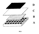
- FIG. 1 shows an exploded schematic view of an electrochemical cell including the membrane structure of the present invention.
- the membrane structure comprises a mechanical support layer A, a porous electrode layer B, and an electrolyte layer C.
- An electrode D having a polarity opposite that of electrode layer B may be applied to the electrolyte layer C by screen printing or other conventional methods to form an electrochemical cell.
- the membrane structure of the present invention yields cells having the advantages of both electrolyte-supported cells (a dense sealing perimeter, high mechanical strength, and thin electrode layers that avoid diffusion limitations) and electrode-supported cells (low ohmic contribution of the electrolyte layer and potential for low temperature operation) without the drawbacks of these conventional designs.
- the electrolyte membrane (layer C of FIG. 1 ) is the thinnest of the three layers, preferably less than 50 microns thick.
- the porous electrode (layer B of FIG. 1 ) preferably is less than 100 microns thick.
- the porous electrode layer in the composite structure is less than 70% dense.
- the green electrode layer may contain pores or the green electrode layer may contain a fugitive material such that pores are formed in the electrode layer after sintering.
- the mechanical support layer preferably is a relatively thick (50-250 micron thick) mesh-like component, preferably a ceramic material including but not limited to a ceramic electrolyte material.
- the material of the support layer is cast, cut, or punched to form a mesh pattern.
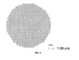
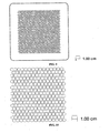
- the mesh pattern may be any network providing a desired ratio of exposed to supported area, of any shape or pattern. Examples of mesh patterns are shown in FIGS. 2 , 6 , 8 , and 10 , but other patterns also may yield satisfactory results.
- a mesh-like pattern of ribs separated by voids is formed in the support layer.
- the ratio of void area to rib area preferably is ⁇ 60/40.
- the ribs preferably have a substantially uniform thickness, generally in the range of 30-300 microns.
- the voids in the structure preferably have a substantially uniform diameter, generally between 0.05 mm and 10 mm, and extend through the thickness of the support layer.
- the voids may define substantially identical shapes or may vary in size and/or shape across a cell to improve overall void packing density.
- the voids define regular polygons, although voids defining circles and other shapes also may be used.
- Hexagonal voids are particularly preferred because they reduce the number of stress concentrating angles, achieve a highly equilibrated stress distribution in the plane during sintering and provide a strong support with a high ratio of exposed to supported area.
- a cross section of the mesh support layer in a plane parallel to the thin electrolyte layer defines a honeycomb-like structure, shown, e.g., in FIG. 2 , which provides excellent access to the dense thin electrolyte layer.
- Each layer may comprise one or more sheets of a ceramic, cermet, or metal material in the green state. Any number of sheets may be used to achieve the desired thickness of each electrolyte layer.
- the use of multiple sheets in the electrolyte layer minimizes the risk of critical continuous defects (e.g. , pinholes) through an electrolyte layer, though it makes achieving thin electrolyte layers difficult.
- the use of multiple sheets in the electrode layer also offers the advantage that sheets of dissimilar compositions can be used to build a composite support layer or functionally grade the electrode to achieve compatibility with a dissimilar electrolyte layer, provide enhanced catalytic or electrochemical function, or other desirable function.
- the mechanical support layer can be produced in a single layer or by consolidating a number of layers to achieve the desired thickness. Lamination increases the complexity of fabrication, but offers a path to laminar composite approaches, which can provide strength enhancements.
- composition of the three layers may, and likely will, differ.
- a more important aspect of the composition of the layers is that the shrinkage of the layers upon thermal processing is similar and no deleterious chemical reactions occur between the respective layers.
- the thin electrolyte layer and the thicker support layer each is selected from a partially stabilized zirconia composition.
- the thin electrolyte layer preferably is a scandia-stabilized zirconia composition.
- Other compositions including but not limited to doped cerium oxides, doped zirconium oxides, lanthanum gallates, bismuth oxide ceramics, other ionic or mixed conducting ceramics, or mixtures of the above, also may yield satisfactory results.
- the mechanical support layer preferably is a partially-stabilized zirconia composition, more preferably, a 6 mol% scandia-stabilized zirconia composition or 3 mol% yttria-stabilized composition.
- compositions including but not limited to doped cerium oxides, dopes zirconium oxides, lanthanum gallates, bismuth oxide ceramics, other ionic or mixed conducting ceramics, metals, cermets or mixtures of the above, also may yield satisfactory results.
- the electrode layer may comprise a wide range of materials and composites.
- the electrode layer may be formed from a composition suitable for performing the anode function or a fuel cell or other electrochemical cell and conducting current under reducing conditions.
- Particularly preferred electrodes in this embodiment include NiO-zirconia composites, NiO-ceria composites, other cermets, metals or ceramics with the above-described properties, and combinations thereof.
- the electrode layer may be formed from a composition suitable for performing the cathode function for a fuel cell or other electrochemical cell.
- Particularly preferred electrodes in this embodiment may comprise electronic or mixed electronic-ionic conductors including lanthanide manganites, ferrites, cobaltites or other conducting ceramics, or cermets or metallic materials that can be cosintered in an appropriate manner with the electrolyte or support.
- the electrode layer in each of the above-described embodiments is porous, with the porosity providing a path for gas diffusion to the electrolyte/electrode interface, a critical region of electrochemical reaction in the resultant electrochemical cell.
- this may be accomplished using either a porous electrode layer or a fugitive-containing electrode material in the green state.
- the thin electrolyte layer may be prepared by tape casting or other processes that yield a sheet or stack of sheets having a thickness of less than 50 microns after firing.
- the thin electrolyte layer may comprise a stack of at least two-sheets in the green state.
- the electrode layer may be prepared by tape casting or other processes that yield a sheet or stack of sheets having a thickness of less than 100 microns after firing, with microscopic porosity in the layer of more than 30% of the fired layer.
- the thin electrode layer may comprise a stack of at least two-sheets in the green state.
- the mechanical support layer may be produced by punching or cutting green sheets produced by tape casting; by conventional casting methods including but not limited to slip casting or gel casting; by dry or semi-dry pressing using isostatic or uniaxial presses; or by printing the pattern by solid freeform fabrication or similar high solids extrusion processes. It also may be possible to produce voids in the thicker support layer by the burn-off of fugitive materials contained within the support layer.
- the support layer preferably comprises a single sheet, although two or more sheets ( e.g ., three and four sheets) also may be used. Multiple sheets may be laminated, e.g ., at 80 °C and 12 MPa.
- the laminated may then be cut using a laser cutting system or similar device to form a network of interconnected ribs separated by voids. This may be accomplished, for example, by cutting the green perform sheet by laser cutting.
- a pattern such as the hexagonal pattern shown in FIG. 2 , may be cut into the laminate including an uncut perimeter area to allow effective sealing with the thin electrolyte layer and encapsulate the electrode layer.
- the cut-out laminate may then be set aside.
- the membrane of the present invention may be prepared by laminating the thin electrolyte layer in the green state to the electrode layer and subsequently to the mechanical support layer in the green state.
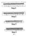
- the process is shown schematically in FIG. 3 .
- Step 1 of FIG. 3 a cross section view of the electrolyte (top), electrode (middle), and mechanical support (bottom) are shown.
- the pieces are laminated by applying isostatic pressure to the stack of tapes, causing the electrolyte layer to deform and encapsulate the electrode layer, as shown in Step 2 of FIG. 3 .
- the electrode layer is smaller radially than the electrolyte and mechanical support layers; the thin electrolyte layer and thick ceramic support layers extend radially outwardly beyond the perimeter of the electrode layer such that after lamination, the electrode layer is encapsulated within the thin electrolyte and ceramic support layers and does not extend to the outer surface of the structure.
- “perimeter” refers to the outer edge of a layer, regardless of the shape of the layer.
- the electrolyte deforms uniformly, avoiding cracking or unequal stress distributions.
- the portions of the laminated thin electrolyte and ceramic support layers extending beyond the perimeter of the electrode layer form a dense sealing perimeter useful in the assembly of electrochemical cell stacks.
- the laminate can then be heat treated to remove the tape casting binders from the laminae, and then sintered to produce a ceramic part with a dense electrolyte layer. During this heat treatment, all the lamina shrink to produce a fired part that is smaller than the green part while maintaining the architecture of the component, as shown in Step 3 of FIG. 3 .
- the sintering of the cell creates a dense ceramic continuum at the perimeter that encapsulates the porous electrode, completely eliminating any lateral gas diffusion paths out of the electrode region.
- Step 4 of FIG. 3 shows the deposition of the opposite electrode, which completes the electrochemical cell.
- the preferred lamination method uses pressure and temperature to bond the two layers by heating above the glass transition temperature of the polymer component of the green support layer to achieve intimate contact and bonding between the layers.
- the layers typically are compressed at temperatures below 100 °C to produce a laminate structure.
- the laminate may be trimmed using a laser cutter.
- a pattern such as that shown in FIG. 2 , may be cut out of the laminate, e.g., using a 30-watt laser, leaving a sealing border of between 0.1 and 3 cm around the pattern of shapes.
- the laminate is then heated to ⁇ 600 °C to remove the polymeric binder.
- the resultant structure is sintered at temperatures above 1000 °C to densify the structure and provide adherence and cohesion layers.
- Electrochemical cells may be prepared from the laminate membrane structure of the present invention by applying appropriate electrode materials to the exposed electrolyte surface. This may be accomplished, for example, by screen printing of electrode inks or other conventional electrode application methods.
- the cathode materials should be a composition suitable for performing the cathode function for a fuel cell or other electrochemical cell, such as electronic or mixed electronic-ionic conductors such as the lanthanide manganites, ferrites, cobaltites or other conducting ceramics, or cermets or metallic materials, or mixtures thereof.
- anode materials for the exposed electrolyte surface may be selected from NiO-zirconia composites, NiO-ceria composites, or other cermets, metals or ceramics, or composites thereof suitable for performing the anode function for a fuel cell or other electrochemical cell and conducting current under reducing conditions.
- a typical cathode electrode is prepared by depositing a first layer of an electrochemically active material (such as a lanthanum manganite and gadolinium-doped ceria powder mixture dispersed in an organic vehicle) and then depositing a second ink layer (such a pure lanthanum manganite powder dispersed in an organic vehicle) as a "current collector.” After sequentially printing and drying the two layers, the cathode is sintered at a temperature of 1150 °C.
- an electrochemically active material such as a lanthanum manganite and gadolinium-doped ceria powder mixture dispersed in an organic vehicle
- a second ink layer such a pure lanthanum manganite powder dispersed in an organic vehicle
- an electrochemically active anode interlayer ink for example a finely divided NiO and a gadolinium-doped ceria powder mixture dispersed in an organic vehicle
- a second electrically conductive ink layer for example a more coarsely divided NiO and yttrium-stabilized zirconia powder mixture dispersed in an organic vehicle
- the second layer serves as a high conductivity "current collector” layer.
- the layers preferably are deposited by applying the ink formulations by screen printing or other conventional application method, including but not limited to aerosol spray deposition, painting, and stencil or transfer printing processes. After sequentially depositing and drying the two layers, the electrode is sintered to a temperature of 1300 °C.
- Electrochemical cell stacks may be prepared from the resulting electrochemical cells by interleaving the cells with conventional dense interconnect plates of an electrically conducting material.
- the dense plates serve to separate air and fuel streams while providing an electrical series connection between the cells.
- the plates may be formed from a dense material that is conductive in both oxidizing and reducing atmospheres, including but not limited to an electronically conductive dense ceramic material, lanthanum chromite, a nickel chromic superalloy, and a ferritic stainless steel.
- An electrochemical stack maybe formed from a minimum of two self-supporting membranes or electrochemical cells and three plates, with the first plate having an inner face adjacent to the support side of the first membrane or cell, the second plate having one face adjacent to the thin electrolyte side of the first membrane or cell and the opposing face adjacent to the support side of the second membrane or cell, and the third plate having an inner face adjacent to the thin electrolyte side of the second membrane or cell. Additional units may be added to the stack with the number of membranes or cells being equal to n and the number of plates being equal to n + 1 .
- a stack may be prepared by connecting the membranes or cells to the plates with a contact paste.
- the contact paste may penetrate the voids in the support to provide electrical contact between the plates and the encapsulated electrode.
- the contact paste may comprise a conducting ceramic material such as a lanthanum chromite, a cermet such as NiO/YSZ, or a metal, such as platinum or silver.
- the dense seal perimeter allows effective stack sealing with the application of small compressive forces.
- the flexibility and strength of the membranes structure allows effective flattening of the structure at lower pressure.
- the conformance required for effective mechanical sealing may be achieved with the external application of a lower mechanical load to the stack.
- the 6ScSZ tapes for the support structure were prepared by a conventional tape casting method and had a thickness of approximately 45 microns in the green state.
- the tape was cut into 15 x 15 cm sheets.
- the sheets were stacked on top each other, five sheets per stack.
- the resulting five-sheet stack was laminated at 80 °C and 12 MPa.
- the pattern shown in FIG. 2 was then cut in the laminate using a laser cutting system. The cut-out laminate was set aside.
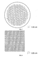
- the porous anode layer was constructed with cast tapes prepared with a nickel oxide and yttria-stabilized zirconia powder mixture. This mixture was made using 60 mol% NiO powder (Novamet) and 40 mol% yttria-stabilized zirconia (Unitec). The thickness of the dry tape was 45 microns. The sheets were then cut by hand to 15 cm x 15 cm, moved to a 30-watt laser cutting system, and cut to form a circle with a diameter 0.5 cm greater than the mesh pattern shown in FIG. 4 .
- the 6ScSZ electrolyte tapes for the thin electrolyte layer were prepared by a conventional tape casting method.
- the thickness of the electrolyte tape was 45 microns.
- the tape was cut into 15 x 15 cm sheets.
- the electrolyte tape was placed on an aluminum setter covered with Mylar.
- the anode layer was stacked on the electrolyte layer, centered on the electrolyte sheet.
- the cut-out support laminate was then placed on top of the anode sheet, again centered to provide a uniform overlap of electrolyte and mechanical support, such that when laminated, the electrode layer would be encapsulated by the overlapping electrolyte and support layers.
- the stack was laminated at 80 °C and 12 MPa. After lamination, the final part was cut out of the laminate based on the pattern shown by the dashed line in FIG. 4 .
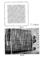
- the resultant component was sintered at 1400 °C for two hours to densify the electrolyte and support layers. A photograph of the resultant component is shown in FIG. 5 .
- the tri-layers were prepared, cast and laminated as described in Example 1.
- the support laminate was laser cut to produce the pattern shown in FIG. 6 .
- the cut-out laminate was set aside.
- the two-sheet electrolyte-electrode stack was prepared as described in Example 1 and laminated with the cut-out support, also as described in Example 1.
- the final part was cut out of the laminate using the pattern shown by the dashed line in FIG. 7 .
- the resultant component was sintered at 1400 °C for two hours to densify the electrolyte and support layers.
- the tri-layers were prepared, cast and laminated as described in Example 1.
- the support laminate was laser cut to produce the pattern shown in FIG. 8 .
- the cut-out laminate was set aside.
- the two-sheet electrolyte-electrode stack was prepared as described in Example 1 and laminated with the cut-out support, also as described in Example 1.
- the final part was cut out of the laminate using the pattern shown by the dashed line in FIG. 9 .
- the resultant component was sintered at 1400 °C for two hours to densify the electrolyte and support layers.
- the tri-Iayers were prepared, cast and laminated as described in Example 1.
- the support laminate was laser cut to produce the pattern shown in FIG. 10 .
- the cut-out laminate was set aside.
- the two-sheet electrolyte-electrode stack was prepared as described in Example 1 and laminated with the cut-out support, also as described in Example 1.
- the final part was cut out of the laminate using the pattern shown by the solid line in FIG. 11 . After sintering at 1400 °C for 2 hours, the component shown in FIG. 12 was produced.
- the tri-layers were prepared, cast and laminated as described in Example 1.
- the support laminate was laser cut to produce the pattern shown in FIG. 13 .
- the cut-out laminate was set aside.
- the two-sheet electrolyte-electrode stack was prepared as described in Example 1 and laminated with the cut-out support, also as described in Example 1.
- the final part was cut out of the laminate using the pattern shown by the dashed line in FIG. 14 .
- the resultant component was sintered at 1400 °C for two hours to densify the electrolyte and support layers.
- a solid oxide fuel cell was prepared using a membrane structure produced as described in Example 1.
- a Sr-doped lanthanum manganite/Gd-doped ceria composite cathode was applied by paint roller on the exposed electrolyte membrane directly opposite the sintered anode.
- the cathode was sintered at 1100 °C to achieve good adherence.
- Platinum meshes were attached to the anode side of the cell using an NiO ink to serve as the anode current collector.
- Silver mesh was attached to the cathode side of the cell using a Sr-doped lanthanum manganite ink to serve as the cathode current collector.
- Alumina felt seals were cut to form a perimeter 1.5 cm wide that enclosed the anode and cathode active areas. The alumina felts were saturated with an aqueous slurry of alumina powder to improve the density of the seal material and prevent gas leakage.
- the cells was heated to 850 °C under air on the cathode side and nitrogen gas on the anode side.
- the cell exhibited a high open circuit voltage in N 2 and was subsequently reduced by substituting hydrogen for nitrogen in the anode gas stream over a one-hour period.
- the cell was initially fed 350 sccm H 2 to the anode side and 1.6 slpm air to the cathode side.
- a measurement of the cell voltage as a function of current density was taken and the data plotted in FIG. 15 .
- the cell was cooled to 750 °C and the voltage measured as a function of current density for various fuel dilutions. The slope of the voltage vs.
- ASR area-specific resistance
- FIG. 16 shows comparative data of three SOFC components.
- the three cells had similar electrode compositions and were tested under equivalent fuel utilization and temperature (750 °C) conditions.
- the primary difference between the samples is the architecture, particularly the thickness of the electrolyte and the intimacy of the electrode-electrolyte interface.
- a conventional electrolyte-supported cell 120 microns thick green tape
- the thinner electrolyte-supported cell shows improved performance, with an ASR value of 0.753 ohm-cm 2 .
- the disclosed architecture with the same electrolyte thickness (45 microns thick green tape) but the most intimate contact between anode and electrolyte, demonstrates the best performance of the three, with an ASR value of 0.421 ohm-cm 2 . Given that all three cells are flexible with good mechanical strength and dense sealing perimeters, the advantages of the disclosed technology are evident.
Description
- Not applicable
- Not applicable
- Not applicable
- The invention relates to thin film membranes of ceramic materials with integral seals and support, electrochemical cells including these membranes, and stacks formed from these electrochemical cells. The disclosed membrane and resultant cell and stack architecture are particularly well suited to applications in which mechanical ruggedness and volumetric and gravimetric reaction density are desirable. This invention may be useful in electrochemical separations and catalytic reactors including but not limited to solid oxide fuel cells and oxygen separation membranes.
- Tubular solid oxide fuel cells (SOFCs) are the most extensively demonstrated of the many designs proposed for SOFCs. In these structures, a multi-layer tube is fabricated with cathode; electrolyte, and anode layers. Tubes that are supported by anodes, cathodes, and electrolytes each have been proposed in the literature and demonstrated. Electrolyte- and cathode-supported tubes, in both circular and flat tube configurations, have been demonstrated by Westinghouse and Siemens-Westinghouse Power Corporation. Anode-supported tubes have been demonstrated by a range of manufacturers.
- In tubular SOFCs, fuel or air is flowed down the center of the tube, depending on whether the tube is anode- or cathode-supported, while the complementary gas mix is flowed outside the tube. Such tubes can have open or closed ends and are typically sealed outside the reaction zone of the SOFC. Conventional tubular cells typically suffer from low volumetric or gravimetric power density because large tubes do not pack well and have a low surface area to volume ratio.
- Microtubular SOFCs, in which small-diameter (i.e., < 5 mm) tubes of electrolyte are slurry coated with cathode and anode components, overcome some of the disadvantages of conventional tubes. Sealing of small diameter microtubes is simpler than sealing of conventional tubes. Microtubular cells also overcome the low surface area to volume ratio associated with conventional tubular cells. However, microtubular cells require complex manifolding and electrical interconnection schemes, which makes scaling to large power stacks difficult.
- Planar SOFCs, which may be supported by either the electrode or the electrolyte, also have been demonstrated extensively. Electrode-supported cells have a thick electrode component that acts as the mechanical load-bearing member of the cell and a thin electrolyte layer. This design reduces electrolyte ohmic resistance in the cell and allows operation at intermediate temperatures (e.g., T < 800 °C). Electrode-supported SOFCs typically are produced by co-sintering the support electrode material and a thin coating of electrolyte material. The electrode support is typically tape cast, calendared, or slip cast, although other preparation methods have been demonstrated. The thin electrolyte can be deposited in a number of ways, including but not limited to lamination of electrolyte tape, screen printing, calendaring, and spray deposition. Electrode-supported cells preferably have an electrolyte that is less than twenty microns in thickness after sintering and well-adhered to the electrode support.
- Electrode-supported planar SOFCs include both cathode- and anode-supported cells. Cathode-supported cells have the potential to be lightweight and lower in cost than anode-supported cells. However, processing of cathode-supported cells is difficult because the cofiring of most cathode materials in contact with an electrolyte produces insulating intermediate compounds. Anode-supported electrolytes are perhaps the most widely evaluated cell geometry for low temperature operation. Processing of anode-supported cells is comparatively easy because sintering temperatures in excess of 1300 °C can be used to achieve dense electrolytes without concern for interaction between the anode material and the supported electrolyte.
- Planar anode-supported cells are particularly attractive for mass market, cost driven applications because of their high areal power density and their advantageous packing efficiency. Performance of anode-supported cells at 700 °C has been demonstrated to be over 1 W/cm2 in small cells at low fuel utilization. With appropriate seal and interconnect technology, power densities greater than 0.4 W/cm2 have been reported for anode-supported cell stacks. However, anode-supported cells are not without drawbacks. When conventional nickel oxide/yttrium-stabilized zirconia (NiO/YSZ) composites are used as support materials, the reduction of NiO to nickel metal creates stress in the electrolyte layer, which may cause considerable deformation during this reduction process. Operating planar anode-supported cells at high power density and high fuel utilization also is difficult; the thick porous layer prevents rapid diffusion of steam away from the electrolyte and results in increased cell area-specific resistance (ASR) at high current density.
- Electrolyte-supported planar cells have an electrolyte layer that provides the mechanical strength of the cell. The electrolyte layer can be produced by tape casting or other methods. Electrodes typically are deposited on the electrolyte layer by screen printing or spray coating and fired in a second step. To achieve strong electrode adhesion, the ink particle size, composition, and surface area must be tailored to the target firing temperature and controlled during fabrication. Electrodes can be sintered in two separate steps or simultaneously, depending upon the requisite temperatures for the cathode and anode. In many cases, the anode ink is fired first because it is more refractory and more difficult to sinter, and the cathode ink is applied and fired in a second step at a lower temperature to minimize the chemical interaction between the electrolyte and cathode.
- Electrolyte-supported cells offer numerous advantages in the production of SOFCs. The sealing of electrolyte-supported cells is simpler than electrode-supported planar cells because a dense electrolyte perimeter can be preserved during cell processing, which provides a dense, smooth surface for sealing operations. Electrolyte-supported cells also have good stability during reduction. Because only a thin layer of anode ink is affected by the reduction process, this process generally has little impact on cell mechanical stability. The gas diffusion path in and out of the thinner anode layer is short, making fuel and steam diffusion limitations less of a concern.
- However, under identical operating conditions, electrolyte-supported cells often exhibit much higher area-specific resistance values than electrode-supported cells because the electrolyte is more resistive than the anode or cathode materials. To compensate for this higher area-specific resistance, the operating temperature for electrolyte-supported cells generally is higher than anode-supported cells using the same materials set. The higher operating temperature of the electrolyte-supported cells can be a drawback, particularly for developers wishing to use metallic interconnect materials.
- In spite of more than thirty years of continuous research in the area of SOFCs, these systems remain far from commercialization. Until SOFC cells are developed that address the shortcomings of existing cell structures, it will be difficult for SOFCs to overcome the commercialization barriers and compete with conventional energy production routes. Considering planar cells in particular, a cell that delivers high performance, high mechanical strength, and easier sealing than current electrolyte- or anode-supported cells is essential in advancing commercialization of SOFCs.
-
US 2004/072057 discloses a ceramic membrane comprising a ceramic electrolyte material, an intermediate porous electrode material and a ceramic electrolyte support material. - The present invention provides a mechanically robust supported ceramic membrane structure as described in
claims - The structure comprises a very thin electrolyte (less than 50 microns) supported by a thin layer of a porous electrode material (less than 100 microns). The two layers form a thin membrane reactor that is supported by a mesh-like mechanical support layer. The membrane structure of the present invention may be prepared by laminating a thin electrolyte layer in the green state with an electrode layer in the green state. The mechanical support may be attached by laminating a third, thicker ceramic layer to the bi-layer, also in the green state. This mechanical support has been preformed to provide a meshed network of support ribs.
- Preferably, the thin electrolyte layer and ceramic support layer extend radially outwardly beyond the perimeter of the electrode layer to form a dense sealing perimeter. This sealing perimeter encapsulates the electrode layer. The electrode layer is sintered to the adjacent surfaces of the thin electrolyte and ceramic support layers within the interior of the structure and does not extend to the outer surface of the structure. The dense sealing perimeter formed by the thin electrolyte layer and the ceramic support layer is particularly well suited for stack fabrication.
- The thin electrolyte layer may be prepared by tape casting or other processes that result in a layer having a thickness of less than 50 microns after firing. The electrode layer may be prepared by tape casting or other processes that result in a layer having a thickness of less than 100 microns after firing. The electrode layer preferably is porous. The electrode material may be porous; alternatively, the electrode material in the green state may contain a fugitive material, resulting in pore formation upon sintering of the electrode layer. The thicker support layers may be produced by punching or cutting green sheets produced by tape casting; by conventional casting methods including but not limited to slip casting or gel casting; by dry or semi-dry pressing using isostatic or uniaxial presses; or by printing the pattern by solid freeform fabrication or similar high solids extrusion processes. Thin layers of ceramic can also be laminated in the green state to form thicker support layers.
- The preferred method for lamination, described herein, is the use of pressure and temperature to bond the three layers by heating the green ceramic tape above the glass transition temperature of the polymer component to achieve intimate contact and bonding between the layers. The electrolyte, electrode and support layers are compressed at temperatures below 100 °C to produce a laminate structure. The laminates are subsequently heated to 600 °C to remove the polymeric binder. The resultant structures are sintered at temperatures above 1000 °C to densify the structure and provide adherence and cohesion between layers.
- The architecture of electrochemical cells including the ceramic membranes of the present invention offer significant advantages in processing, electrochemical performance, mechanical integrity, the sealing of stacks, and the facility of gas flow compared to electrode-supported cells. This architecture also provides a means of translating the advantages of thin electrolytes to a robust electrolyte-supported structure.
- The planar structure of the present invention also provides a flexible platform for a range of electrochemical cells by the selection of appropriate electrode layers (either anode or cathode layers can be considered for the porous layer) and corresponding vehicles such as screen printing inks. The simple planar geometry of the cell also allows the use of existing electrode materials and processes developed for both electrode- and electrolyte-supported cells. The membranes and cells of the present invention are particularly well-suited to large volume manufacturing and low cost processes.
- The mesh-like mechanical support creates a macroscopic texture on at least one side of the disclosed cells and, together with the electrolyte layer, serves to encapsulate the edges of the electrode layer. In the disclosed examples, the anode layer is encapsulated on this textured side of the structure and the cathode is deposited on the opposing side. Conceptually equivalent cells could be produced in which the cathode layer supports the electrolyte and is encapsulated by the electrolyte and support, while the anode layer is deposited on the untextured side of the cell.
- The dense seal perimeter of the present invention is particularly well suited for stack fabrication. Fuel cell stacks can be produced by interleaving electrochemical cells formed using disclosed structure with dense interconnect plates. The interconnect plates separate the air and fuel streams while providing an electrical series connection between the cells. The strength and flexibility of the proposed membrane structure allows the resultant cells to achieve cell-to interconnect conformance during stack assembly by applying small compressive forces; good contact along the perimeter improves stack sealing while good area contact between the cells and the interconnect reduces stack resistance.
- In one embodiment, the invention provides a ceramic membrane comprising a thin ceramic electrolyte layer, an intermediate porous electrode layer supporting the thin ceramic electrolyte layer, and a thick ceramic layer supporting the intermediate layer; the ceramic support layer defines a plurality of voids separated by a network of support ribs. The thin electrolyte layer and the ceramic support layer each may extend radially outwardly beyond the perimeter of the porous electrode layer to defme a sealing perimeter that encapsulates the porous electrode layer. The porous electrode layer also may define a perimeter spaced inwardly from the perimeters of the thin electrolyte layer and the ceramic support layer such that the thin electrolyte layer and the ceramic support layer define a sealing perimeter that encapsulates the porous electrode layer. The porous electrode layer may be formed by sintering a fugitive-containing ceramic electrode material in the green state.
- In another embodiment, the invention provides a ceramic membrane comprising a thin layer comprising a ceramic electrolyte material in the green state, an intermediate layer supporting the thin electrolyte layer, and a thicker layer supporting the intermediate layer. The support material comprises a ceramic material in the green state and defining a plurality of voids separated by a network of support ribs; the intermediate layer comprises a fugitive-containing electrode material in the green state or a porous electrode material in the green state. The tri-layer assembly is laminated and then sintered to form a composite structure having a porous intermediate layer. The thin electrolyte layer and the support layer each may extend radially outwardly beyond the perimeter of the porous electrode layer to define a sealing perimeter that encapsulates the porous electrode layer. The porous electrode layer also may define a perimeter spaced inwardly from the perimeters of the thin electrolyte layer and the ceramic support layer such that the electrolyte layer and the ceramic support layer define a sealing perimeter that encapsulates the porous electrode layer.
- Other embodiments of the invention include electrochemical cells comprising any of the above-described ceramic membranes and a second electrode layer deposited on the thin electrolyte surface. The second electrode layer has a polarity opposite that of the porous or encapsulated electrode.
- The invention also provides electrochemical cell stacks that include the above-described electrochemical cells. In one embodiment, the electrochemical cell stack comprises a first dense electronically conductive plate, an electrochemical cell with the first plate adjacent to its support surface and in electrical contact with its porous or encapsulated electrode, a second dense electronically conductive late in electrical contact with the electrode deposited on its thin electrolyte, a second electrochemical cell with the second plate adjacent to its support surface and in electrical contact with its porous or encapsulated electrode, and a third dense electronically conductive plate in electrical contact with the electrode deposited on the second cell's thin electrolyte. At least one dense electronically conductive plate may be nickel chrome superalloy, a ferritic stainless steel, or a lanthanum chromite.
- In another embodiment, the electrochemical cell stack comprises n electrochemical cells, as described above, wherein n ≥ 2, and n + 1 dense electronically conductive plates. Each of n - 1 plates is adjacent to the support of one of the n electrochemical cells and in electrical contact with both the porous or encapsulated electrode of the same cell and the electrode deposited on the thin electrolyte of another one of the n electrochemical cells. Each of the remaining 2 plates is in electrical contact with an outer surface of one of the outermost of the n electrochemical cells.
- The invention also provides planar ceramic membrane structures for an electrochemical cell. In one embodiment, the planar ceramic membrane structure comprises a dense electrolyte, a dense mechanical support perforated by an plurality of voids, a porous electrode that defines the active area of the cell, and a dense circumferential region that provides an edge seal to the active area. The porous electrode is encapsulated within the dense electrolyte, dense mechanical support, and dense circumferential region. In another embodiment, the planar ceramic membrane structure comprises a dense electrolyte, a dense mechanical support perforated by a plurality of voids, and a porous electrode material that defines the active area of the cell. The dense electrolyte and dense mechanical support cooperate to encapsulate the porous electrode within the structure and form a dense circumferential region that provides an edge seal to the active area.
- These and further objects of the invention will become apparent from the following detailed description.
-
FIG. 1 is an exploded schematic view of an electrochemical cell of the present invention, particularly illustrating the membrane structure. -
FIG. 2 is a cutting pattern for the support layer of the membrane structure of Example 1. -
FIG 3 . is an exploded schematic view of the components during various steps in the assembly and processing of one embodiment of the invention, particularly illustrating the cross sectional architecture of the structure and the sequence of layer fabrication. -
FIG. 4 is the final cutting pattern (dashed line) of the membrane structure of Examples 1. -
FIG. 5 is a photograph of the composite structure produced after sintering the membrane structure of Example 1. -
FIG. 6 is a cutting pattern for the support layer of the membrane structure of Example 2. -
FIG. 7 is the final cutting pattern (dashed line) of the membrane structure of Example 2. -
FIG. 8 is a cutting pattern for the support layer of the membrane structure of Example 3. -
FIG. 9 is the final cutting pattern (dashed line) of the membrane structure of Example 3. -
FIG. 10 is a cutting pattern for the support layer of the membrane structure of Example 4. -
FIG. 11 is the final cutting pattern (dashed line) of the membrane structure of Example 4. -
FIG. 12 is a photograph of the composite structure produced after sintering the membrane structure of Example 4. -
FIG. 13 is the cutting pattern for the support layer of the membrane structure of Example 5. -
FIG. 14 is the final cutting pattern (dashed line) of the membrane structure of Example 5. -
FIG. 15 is a graph of the fuel cell performance of the cell of Example 6 at 850 and 750 °C. -
FIG. 16 is a graph of comparative fuel cell performance at 750 °C for the cell of Example 6 and conventional fuel cells. - The present invention provides a membrane structure useful in electrochemical cells. When appropriate electrode materials are included in the structure and applied to the exposed electrolyte surface, the structure may form a fuel cell, oxygen separator, or other electrochemical device. The resultant electrochemical cells may be assembled and electrically connected to form stacks.
-
FIG. 1 shows an exploded schematic view of an electrochemical cell including the membrane structure of the present invention. The membrane structure comprises a mechanical support layer A, a porous electrode layer B, and an electrolyte layer C. An electrode D having a polarity opposite that of electrode layer B may be applied to the electrolyte layer C by screen printing or other conventional methods to form an electrochemical cell. The membrane structure of the present invention yields cells having the advantages of both electrolyte-supported cells (a dense sealing perimeter, high mechanical strength, and thin electrode layers that avoid diffusion limitations) and electrode-supported cells (low ohmic contribution of the electrolyte layer and potential for low temperature operation) without the drawbacks of these conventional designs. - The electrolyte membrane (layer C of
FIG. 1 ) is the thinnest of the three layers, preferably less than 50 microns thick. The porous electrode (layer B ofFIG. 1 ) preferably is less than 100 microns thick. Preferably, the porous electrode layer in the composite structure is less than 70% dense. The green electrode layer may contain pores or the green electrode layer may contain a fugitive material such that pores are formed in the electrode layer after sintering. - The mechanical support layer preferably is a relatively thick (50-250 micron thick) mesh-like component, preferably a ceramic material including but not limited to a ceramic electrolyte material. Preferably, the material of the support layer is cast, cut, or punched to form a mesh pattern. The mesh pattern may be any network providing a desired ratio of exposed to supported area, of any shape or pattern. Examples of mesh patterns are shown in
FIGS. 2 ,6 ,8 , and10 , but other patterns also may yield satisfactory results. - A mesh-like pattern of ribs separated by voids is formed in the support layer. The ratio of void area to rib area preferably is ≥60/40. The ribs preferably have a substantially uniform thickness, generally in the range of 30-300 microns. The voids in the structure preferably have a substantially uniform diameter, generally between 0.05 mm and 10 mm, and extend through the thickness of the support layer. The voids may define substantially identical shapes or may vary in size and/or shape across a cell to improve overall void packing density. Preferably, the voids define regular polygons, although voids defining circles and other shapes also may be used. Hexagonal voids are particularly preferred because they reduce the number of stress concentrating angles, achieve a highly equilibrated stress distribution in the plane during sintering and provide a strong support with a high ratio of exposed to supported area. In a preferred embodiment, a cross section of the mesh support layer in a plane parallel to the thin electrolyte layer defines a honeycomb-like structure, shown, e.g., in
FIG. 2 , which provides excellent access to the dense thin electrolyte layer. - Each layer may comprise one or more sheets of a ceramic, cermet, or metal material in the green state. Any number of sheets may be used to achieve the desired thickness of each electrolyte layer. The use of multiple sheets in the electrolyte layer minimizes the risk of critical continuous defects (e.g., pinholes) through an electrolyte layer, though it makes achieving thin electrolyte layers difficult. The use of multiple sheets in the electrode layer also offers the advantage that sheets of dissimilar compositions can be used to build a composite support layer or functionally grade the electrode to achieve compatibility with a dissimilar electrolyte layer, provide enhanced catalytic or electrochemical function, or other desirable function. The mechanical support layer can be produced in a single layer or by consolidating a number of layers to achieve the desired thickness. Lamination increases the complexity of fabrication, but offers a path to laminar composite approaches, which can provide strength enhancements.
- The composition of the three layers may, and likely will, differ. A more important aspect of the composition of the layers is that the shrinkage of the layers upon thermal processing is similar and no deleterious chemical reactions occur between the respective layers. In some cases, for example, it may be preferred to have a mechanically strong, relatively poor conductor in the mechanical support, a highly conductive electron conductor in the porous layer, and a mechanically weaker but excellent ionic conductor in the electrolyte.
- Preferably, the thin electrolyte layer and the thicker support layer each is selected from a partially stabilized zirconia composition. The thin electrolyte layer preferably is a scandia-stabilized zirconia composition. Other compositions, including but not limited to doped cerium oxides, doped zirconium oxides, lanthanum gallates, bismuth oxide ceramics, other ionic or mixed conducting ceramics, or mixtures of the above, also may yield satisfactory results. The mechanical support layer preferably is a partially-stabilized zirconia composition, more preferably, a 6 mol% scandia-stabilized zirconia composition or 3 mol% yttria-stabilized composition. Other compositions, including but not limited to doped cerium oxides, dopes zirconium oxides, lanthanum gallates, bismuth oxide ceramics, other ionic or mixed conducting ceramics, metals, cermets or mixtures of the above, also may yield satisfactory results.
- The electrode layer may comprise a wide range of materials and composites. In one embodiment, the electrode layer may be formed from a composition suitable for performing the anode function or a fuel cell or other electrochemical cell and conducting current under reducing conditions. Particularly preferred electrodes in this embodiment include NiO-zirconia composites, NiO-ceria composites, other cermets, metals or ceramics with the above-described properties, and combinations thereof. In another embodiment, the electrode layer may be formed from a composition suitable for performing the cathode function for a fuel cell or other electrochemical cell. Particularly preferred electrodes in this embodiment may comprise electronic or mixed electronic-ionic conductors including lanthanide manganites, ferrites, cobaltites or other conducting ceramics, or cermets or metallic materials that can be cosintered in an appropriate manner with the electrolyte or support.
- Preferably, the electrode layer in each of the above-described embodiments is porous, with the porosity providing a path for gas diffusion to the electrolyte/electrode interface, a critical region of electrochemical reaction in the resultant electrochemical cell. As described above, this may be accomplished using either a porous electrode layer or a fugitive-containing electrode material in the green state.
- The thin electrolyte layer may be prepared by tape casting or other processes that yield a sheet or stack of sheets having a thickness of less than 50 microns after firing. The thin electrolyte layer may comprise a stack of at least two-sheets in the green state. The electrode layer may be prepared by tape casting or other processes that yield a sheet or stack of sheets having a thickness of less than 100 microns after firing, with microscopic porosity in the layer of more than 30% of the fired layer. Like the thin electrolyte layer, the thin electrode layer may comprise a stack of at least two-sheets in the green state.
- The mechanical support layer may be produced by punching or cutting green sheets produced by tape casting; by conventional casting methods including but not limited to slip casting or gel casting; by dry or semi-dry pressing using isostatic or uniaxial presses; or by printing the pattern by solid freeform fabrication or similar high solids extrusion processes. It also may be possible to produce voids in the thicker support layer by the burn-off of fugitive materials contained within the support layer. For tape cast sheets, the support layer preferably comprises a single sheet, although two or more sheets (e.g., three and four sheets) also may be used. Multiple sheets may be laminated, e.g., at 80 °C and 12 MPa. The laminated may then be cut using a laser cutting system or similar device to form a network of interconnected ribs separated by voids. This may be accomplished, for example, by cutting the green perform sheet by laser cutting. A pattern, such as the hexagonal pattern shown in
FIG. 2 , may be cut into the laminate including an uncut perimeter area to allow effective sealing with the thin electrolyte layer and encapsulate the electrode layer. The cut-out laminate may then be set aside. - In one embodiment, the membrane of the present invention may be prepared by laminating the thin electrolyte layer in the green state to the electrode layer and subsequently to the mechanical support layer in the green state. The process is shown schematically in
FIG. 3 . InStep 1 ofFIG. 3 , a cross section view of the electrolyte (top), electrode (middle), and mechanical support (bottom) are shown. - The pieces are laminated by applying isostatic pressure to the stack of tapes, causing the electrolyte layer to deform and encapsulate the electrode layer, as shown in
Step 2 ofFIG. 3 . Although the drawings ofFIG. 3 are not to scale, it is important to note that the electrode layer is smaller radially than the electrolyte and mechanical support layers; the thin electrolyte layer and thick ceramic support layers extend radially outwardly beyond the perimeter of the electrode layer such that after lamination, the electrode layer is encapsulated within the thin electrolyte and ceramic support layers and does not extend to the outer surface of the structure. As used herein, "perimeter" refers to the outer edge of a layer, regardless of the shape of the layer. By applying isostatic force to the laminate at temperatures above the glass transition of the tape binder, the electrolyte deforms uniformly, avoiding cracking or unequal stress distributions. Preferably, the portions of the laminated thin electrolyte and ceramic support layers extending beyond the perimeter of the electrode layer form a dense sealing perimeter useful in the assembly of electrochemical cell stacks. - The laminate can then be heat treated to remove the tape casting binders from the laminae, and then sintered to produce a ceramic part with a dense electrolyte layer. During this heat treatment, all the lamina shrink to produce a fired part that is smaller than the green part while maintaining the architecture of the component, as shown in
Step 3 ofFIG. 3 . The sintering of the cell creates a dense ceramic continuum at the perimeter that encapsulates the porous electrode, completely eliminating any lateral gas diffusion paths out of the electrode region.Step 4 ofFIG. 3 shows the deposition of the opposite electrode, which completes the electrochemical cell. - The preferred lamination method uses pressure and temperature to bond the two layers by heating above the glass transition temperature of the polymer component of the green support layer to achieve intimate contact and bonding between the layers. The layers typically are compressed at temperatures below 100 °C to produce a laminate structure. After lamination, the laminate may be trimmed using a laser cutter. A pattern, such as that shown in
FIG. 2 , may be cut out of the laminate, e.g., using a 30-watt laser, leaving a sealing border of between 0.1 and 3 cm around the pattern of shapes. The laminate is then heated to ~600 °C to remove the polymeric binder. The resultant structure is sintered at temperatures above 1000 °C to densify the structure and provide adherence and cohesion layers. - Electrochemical cells may be prepared from the laminate membrane structure of the present invention by applying appropriate electrode materials to the exposed electrolyte surface. This may be accomplished, for example, by screen printing of electrode inks or other conventional electrode application methods. In the case of a cell with an anode layer encapsulated between the electrolyte and the support, the cathode materials should be a composition suitable for performing the cathode function for a fuel cell or other electrochemical cell, such as electronic or mixed electronic-ionic conductors such as the lanthanide manganites, ferrites, cobaltites or other conducting ceramics, or cermets or metallic materials, or mixtures thereof. For a cell with an encapsulated cathode layer, anode materials for the exposed electrolyte surface may be selected from NiO-zirconia composites, NiO-ceria composites, or other cermets, metals or ceramics, or composites thereof suitable for performing the anode function for a fuel cell or other electrochemical cell and conducting current under reducing conditions.
- Screen printing is a preferred method of electrode deposition on the exposed electrolyte, although other conventional methods may be used. A typical cathode electrode is prepared by depositing a first layer of an electrochemically active material (such as a lanthanum manganite and gadolinium-doped ceria powder mixture dispersed in an organic vehicle) and then depositing a second ink layer (such a pure lanthanum manganite powder dispersed in an organic vehicle) as a "current collector." After sequentially printing and drying the two layers, the cathode is sintered at a temperature of 1150 °C. For anode electrodes, an electrochemically active anode interlayer ink (for example a finely divided NiO and a gadolinium-doped ceria powder mixture dispersed in an organic vehicle), will first be deposited and then a second electrically conductive ink layer (for example a more coarsely divided NiO and yttrium-stabilized zirconia powder mixture dispersed in an organic vehicle) would be deposited on top of the interlayer. The second layer serves as a high conductivity "current collector" layer. The layers preferably are deposited by applying the ink formulations by screen printing or other conventional application method, including but not limited to aerosol spray deposition, painting, and stencil or transfer printing processes. After sequentially depositing and drying the two layers, the electrode is sintered to a temperature of 1300 °C.
- Electrochemical cell stacks may be prepared from the resulting electrochemical cells by interleaving the cells with conventional dense interconnect plates of an electrically conducting material. The dense plates serve to separate air and fuel streams while providing an electrical series connection between the cells. The plates may be formed from a dense material that is conductive in both oxidizing and reducing atmospheres, including but not limited to an electronically conductive dense ceramic material, lanthanum chromite, a nickel chromic superalloy, and a ferritic stainless steel.
- An electrochemical stack maybe formed from a minimum of two self-supporting membranes or electrochemical cells and three plates, with the first plate having an inner face adjacent to the support side of the first membrane or cell, the second plate having one face adjacent to the thin electrolyte side of the first membrane or cell and the opposing face adjacent to the support side of the second membrane or cell, and the third plate having an inner face adjacent to the thin electrolyte side of the second membrane or cell. Additional units may be added to the stack with the number of membranes or cells being equal to n and the number of plates being equal to n + 1.
- A stack may be prepared by connecting the membranes or cells to the plates with a contact paste. The contact paste may penetrate the voids in the support to provide electrical contact between the plates and the encapsulated electrode. The contact paste may comprise a conducting ceramic material such as a lanthanum chromite, a cermet such as NiO/YSZ, or a metal, such as platinum or silver.
- The dense seal perimeter allows effective stack sealing with the application of small compressive forces. The flexibility and strength of the membranes structure allows effective flattening of the structure at lower pressure. The conformance required for effective mechanical sealing may be achieved with the external application of a lower mechanical load to the stack.
- Examples of membrane structures and electrochemical cells according to the present invention are described below. These examples are intended to illustrate and assist in understating the invention but not to limit the scope of the invention to the described examples.
- The tri-layers were constructed with electrolyte and support tapes prepared with 6 mol% scandium-stabilized zirconia powder (initial SSA = 8.704 m2/g). The 6ScSZ tapes for the support structure were prepared by a conventional tape casting method and had a thickness of approximately 45 microns in the green state. The tape was cut into 15 x 15 cm sheets. The sheets were stacked on top each other, five sheets per stack. The resulting five-sheet stack was laminated at 80 °C and 12 MPa. The pattern shown in
FIG. 2 was then cut in the laminate using a laser cutting system. The cut-out laminate was set aside. - The porous anode layer was constructed with cast tapes prepared with a nickel oxide and yttria-stabilized zirconia powder mixture. This mixture was made using 60 mol% NiO powder (Novamet) and 40 mol% yttria-stabilized zirconia (Unitec). The thickness of the dry tape was 45 microns. The sheets were then cut by hand to 15 cm x 15 cm, moved to a 30-watt laser cutting system, and cut to form a circle with a diameter 0.5 cm greater than the mesh pattern shown in
FIG. 4 . - The 6ScSZ electrolyte tapes for the thin electrolyte layer were prepared by a conventional tape casting method. The thickness of the electrolyte tape was 45 microns. The tape was cut into 15 x 15 cm sheets.
- For lamination of the structure, the electrolyte tape was placed on an aluminum setter covered with Mylar. The anode layer was stacked on the electrolyte layer, centered on the electrolyte sheet. The cut-out support laminate was then placed on top of the anode sheet, again centered to provide a uniform overlap of electrolyte and mechanical support, such that when laminated, the electrode layer would be encapsulated by the overlapping electrolyte and support layers. The stack was laminated at 80 °C and 12 MPa. After lamination, the final part was cut out of the laminate based on the pattern shown by the dashed line in
FIG. 4 . The resultant component was sintered at 1400 °C for two hours to densify the electrolyte and support layers. A photograph of the resultant component is shown inFIG. 5 . - The tri-layers were prepared, cast and laminated as described in Example 1. The support laminate was laser cut to produce the pattern shown in
FIG. 6 . The cut-out laminate was set aside. The two-sheet electrolyte-electrode stack was prepared as described in Example 1 and laminated with the cut-out support, also as described in Example 1. The final part was cut out of the laminate using the pattern shown by the dashed line inFIG. 7 . The resultant component was sintered at 1400 °C for two hours to densify the electrolyte and support layers. - The tri-layers were prepared, cast and laminated as described in Example 1. The support laminate was laser cut to produce the pattern shown in
FIG. 8 . The cut-out laminate was set aside. The two-sheet electrolyte-electrode stack was prepared as described in Example 1 and laminated with the cut-out support, also as described in Example 1. The final part was cut out of the laminate using the pattern shown by the dashed line inFIG. 9 . The resultant component was sintered at 1400 °C for two hours to densify the electrolyte and support layers. - The tri-Iayers were prepared, cast and laminated as described in Example 1. The support laminate was laser cut to produce the pattern shown in
FIG. 10 . The cut-out laminate was set aside. The two-sheet electrolyte-electrode stack was prepared as described in Example 1 and laminated with the cut-out support, also as described in Example 1. The final part was cut out of the laminate using the pattern shown by the solid line inFIG. 11 . After sintering at 1400 °C for 2 hours, the component shown inFIG. 12 was produced. - The tri-layers were prepared, cast and laminated as described in Example 1. The support laminate was laser cut to produce the pattern shown in
FIG. 13 . The cut-out laminate was set aside. The two-sheet electrolyte-electrode stack was prepared as described in Example 1 and laminated with the cut-out support, also as described in Example 1. The final part was cut out of the laminate using the pattern shown by the dashed line inFIG. 14 . The resultant component was sintered at 1400 °C for two hours to densify the electrolyte and support layers. - A solid oxide fuel cell was prepared using a membrane structure produced as described in Example 1. A Sr-doped lanthanum manganite/Gd-doped ceria composite cathode was applied by paint roller on the exposed electrolyte membrane directly opposite the sintered anode. The cathode was sintered at 1100 °C to achieve good adherence. Platinum meshes were attached to the anode side of the cell using an NiO ink to serve as the anode current collector. Silver mesh was attached to the cathode side of the cell using a Sr-doped lanthanum manganite ink to serve as the cathode current collector. Alumina felt seals were cut to form a perimeter 1.5 cm wide that enclosed the anode and cathode active areas. The alumina felts were saturated with an aqueous slurry of alumina powder to improve the density of the seal material and prevent gas leakage.
- The cells was heated to 850 °C under air on the cathode side and nitrogen gas on the anode side. The cell exhibited a high open circuit voltage in N2 and was subsequently reduced by substituting hydrogen for nitrogen in the anode gas stream over a one-hour period. At the end of the reduction process, the cell was initially fed 350 sccm H2 to the anode side and 1.6 slpm air to the cathode side. A measurement of the cell voltage as a function of current density was taken and the data plotted in
FIG. 15 . The cell was cooled to 750 °C and the voltage measured as a function of current density for various fuel dilutions. The slope of the voltage vs. current density curve was calculated and divided by the active area of the cell to determine the area-specific resistance (ASR) of the cell. The ASR values of the test cell was calculated to be 0.279 ohm-cm2 at 850 °C and 0.420 ohm-cm2 at 750 °C. - The impact of the cell structure on performance can be appreciated more clearly in
FIG. 16 , which shows comparative data of three SOFC components. The three cells had similar electrode compositions and were tested under equivalent fuel utilization and temperature (750 °C) conditions. The primary difference between the samples is the architecture, particularly the thickness of the electrolyte and the intimacy of the electrode-electrolyte interface. As shown inFIG. 15 , a conventional electrolyte-supported cell (120 microns thick green tape) has a relatively high ASR value of 1.01 ohm-cm2. The thinner electrolyte-supported cell (45 microns thick green tape) shows improved performance, with an ASR value of 0.753 ohm-cm2. The disclosed architecture with the same electrolyte thickness (45 microns thick green tape) but the most intimate contact between anode and electrolyte, demonstrates the best performance of the three, with an ASR value of 0.421 ohm-cm2. Given that all three cells are flexible with good mechanical strength and dense sealing perimeters, the advantages of the disclosed technology are evident.
Claims (14)
- A ceramic membrane, comprising a sintered planar laminate of:at least one layer of a ceramic electrolyte material;at least one layer of an intermediate porous electrode material positioned adjacent to and supporting the ceramic electrolyte material; andat least one layer of a ceramic electrolyte support material positioned adjacent to and supporting the porous electrode material, the ceramic electrolyte support material comprising a network of support ribs defining a plurality of separated voids,wherein the ceramic electrolyte material and the ceramic electrolyte support material each extend outwardly beyond the perimeter of the porous electrode material to define a planar sealing perimeter that encapsulates the porous electrode material;characterised in that the ceramic electrolyte material has a thickness less than 50 µm and the porous electrode material has a thickness less than 100 µm, and further wherein the porous electrode material is thicker than the ceramic electrolyte material, and the ceramic electrolyte support material is thicker than the porous electrode material.
- A ceramic membrane for an electrochemical cell, comprising a planar sintered laminate of:a ceramic electrolyte material;an intermediate porous electrode material positioned adjacent to the ceramic electrolyte material and defining an active area; anda ceramic electrolyte support material positioned adjacent to and supporting the porous electrode material, the ceramic electrolyte support material having a plurality of voids separated by a network of support ribs, wherein the voids extend through the thickness of the ceramic electrolyte support material and are configured to provide a path for gas diffusion to the active area,wherein the ceramic electrolyte material and the ceramic electrolyte support material each extend outwardly beyond the perimeter of the porous electrode material to define a planar sealing perimeter that encapsulates the porous electrode material;characterised in that the ceramic electrolyte material has a thickness less than 50 µm and the porous electrode material has a thickness less than 100 µm, and further wherein the porous electrode material is thicker than the ceramic electrolyte material, and the ceramic electrolyte support material is thicker than the porous electrode material.
- The ceramic membrane of claim 1 or 2, wherein the ceramic electrolyte support material has a thickness less than 300 µm.
- The ceramic membrane of claim 1, 2 or 3, wherein the ceramic electrolyte comprises scandia-stabilized zirconia, doped cerium oxide, doped zirconium oxide, lanthanum gallate, bismuth oxide, or mixtures thereof.
- The ceramic membrane of any preceding claim, wherein the sealing perimeter is dense and extends from the perimeter of the intermediate electrode material to the perimeter of the ceramic membrane, and further wherein the entire sealing perimeter has a thickness equal to the combined thicknesses of the ceramic electrolyte material and the ceramic electrolyte support material.
- The ceramic membrane of any of the preceding claims, wherein both the ceramic electrolyte material and the and the ceramic electrolyte support material comprise Scandia-stabilized zirconia.
- The ceramic membrane of any preceding claim, wherein the ceramic electrolyte support material has a thickness of 50 µm to 250 µm.
- An electrochemical cell, comprising:the planar ceramic membrane of any preceding claim; andat least one layer of a second porous electrode material deposited on a surface of the ceramic electrolyte material, the second electrode material having a polarity opposite that of the encapsulated porous electrode material.
- An electrochemical cell stack, comprising:a first electronically conductive plate;a first electrochemical cell as defined in claim 8, the first electronically conductive plate being positioned adjacent to the ceramic electrolyte support material of the first cell and in electrical contact with the encapsulated porous electrode material of the first cell;a second electronically conductive plate in electrical contact with the second porous electrode material deposited on the ceramic electrolyte material of the first cell;a second electrochemical cell as defined in claim 8, the second electronically conductive plate being positioned adjacent to the ceramic electrolyte support material of the second cell and in electrical contact with the encapsulated porous electrode material of the second cell; anda third electronically conductive plate in electrical contact with the second porous electrode material deposited on the ceramic electrolyte material of the second cell.
- The electrochemical cell stack of claim 9, wherein at least one of the first and second conductive plates is in electrical contact with the encapsulated porous electrode material of the first and second cells through the voids in the electrolyte support material of the first and second cells, respectively.
- The electrochemical cell stack of claim 9, wherein at least one of the first, second and third electronically conductive plates comprises a nickel chrome superalloy, a ferritic stainless steel, or a lanthanum chromite.
- An electrochemical cell stack, comprising:n electrochemical cells as defined in claim 8, wherein n ≥ 2; andn + 1 electronically conductive plates;wherein each of n - 1 plates is adjacent to the ceramic electrolyte support material of one of the n electrochemical cells and in electrical contact with both the encapsulated porous electrode material of the same cell and the second porous electrode material deposited on the ceramic electrolyte material of another one of the n electrochemical cells, and each of the remaining two plates is in electrical contact with an outer surface of one of the outermost of the n electrochemical cells.
- The electrochemical cell stack of claim 12, wherein said each of n-1 plates is in electrical contact with the encapsulated porous electrode material of an adjacent cell through the voids in the electrolyte support material of the cell.
- The electrochemical cell stack of claim 13, further comprising a contact paste for providing electrical contact between said each of n-1 plates and the encapsulated porous electrode material of an adjacent cell through said voids.
Applications Claiming Priority (2)
| Application Number | Priority Date | Filing Date | Title |
|---|---|---|---|
| US11/220,361 US7736787B2 (en) | 2005-09-06 | 2005-09-06 | Ceramic membranes with integral seals and support, and electrochemical cells and electrochemical cell stacks including the same |
| PCT/US2006/034643 WO2007030491A2 (en) | 2005-09-06 | 2006-09-06 | Ceramic membranes with integral seals and support, and electrochemical cells and electrochemical cell stacks including the same |
Publications (3)
| Publication Number | Publication Date |
|---|---|
| EP1932202A2 EP1932202A2 (en) | 2008-06-18 |
| EP1932202A4 EP1932202A4 (en) | 2012-01-11 |
| EP1932202B1 true EP1932202B1 (en) | 2014-06-04 |
Family
ID=37830374
Family Applications (1)
| Application Number | Title | Priority Date | Filing Date |
|---|---|---|---|
| EP06803014.7A Not-in-force EP1932202B1 (en) | 2005-09-06 | 2006-09-06 | Ceramic membranes with integral seals and support, and electrochemical cells and electrochemical cell stacks including the same |
Country Status (9)
| Country | Link |
|---|---|
| US (1) | US7736787B2 (en) |
| EP (1) | EP1932202B1 (en) |
| JP (1) | JP2009507356A (en) |
| KR (1) | KR101045168B1 (en) |
| CN (1) | CN101300709A (en) |
| AU (1) | AU2006287617B2 (en) |
| CA (1) | CA2621252A1 (en) |
| RU (1) | RU2008113055A (en) |
| WO (1) | WO2007030491A2 (en) |
Families Citing this family (28)
| Publication number | Priority date | Publication date | Assignee | Title |
|---|---|---|---|---|
| US8192888B2 (en) * | 2005-04-19 | 2012-06-05 | Nextech Materials, Ltd. | Two layer electrolyte supported fuel cell stack |
| US9985295B2 (en) * | 2005-09-26 | 2018-05-29 | General Electric Company | Solid oxide fuel cell structures, and related compositions and processes |
| US8580453B2 (en) * | 2006-03-31 | 2013-11-12 | General Electric Company | Electrode-supported ceramic fuel cell containing laminar composite electrode including porous support electrode, patterned structure layer and electrolyte |
| JP5242971B2 (en) * | 2007-08-08 | 2013-07-24 | 日本特殊陶業株式会社 | Solid oxide fuel cell |
| DK2181476T3 (en) * | 2007-08-22 | 2015-05-18 | Hexis Ag | Electrode for solid oxide reactor and solid oxide reactor |
| EP2043187B1 (en) * | 2007-09-28 | 2014-08-06 | Dai Nippon Printing Co., Ltd. | Solid oxide fuel cell and manufacturing method thereof |
| US8828618B2 (en) * | 2007-12-07 | 2014-09-09 | Nextech Materials, Ltd. | High performance multilayer electrodes for use in reducing gases |
| US20090148743A1 (en) * | 2007-12-07 | 2009-06-11 | Day Michael J | High performance multilayer electrodes for use in oxygen-containing gases |
| JP5198908B2 (en) * | 2008-03-11 | 2013-05-15 | 行政院原子能委員會核能研究所 | A method for producing a completely dense electrolyte layer laminated on a high performance solid oxide fuel cell membrane electrode assembly (SOFC-MEA). |
| KR101741849B1 (en) * | 2008-12-08 | 2017-05-30 | 넥스테크 머티리얼스, 엘티디. | Current collectors for solid oxide fuel cell stacks |
| JP5431808B2 (en) * | 2009-07-01 | 2014-03-05 | 日本碍子株式会社 | Method for producing laminated fired body |
| FR2961350B1 (en) * | 2010-06-11 | 2012-08-03 | Commissariat Energie Atomique | PROCESS FOR THE PRODUCTION OF ELEMENTARY ELECTROCHEMICAL CELLS FOR ELECTROCHEMICAL SYSTEMS PRODUCING ENERGY OR HYDROGEN, IN PARTICULAR OF THE SOFC AND EHT TYPE |
| KR101177621B1 (en) * | 2010-06-25 | 2012-08-27 | 한국생산기술연구원 | Manufacturing method of SOFC unit cell |
| FR2964664B1 (en) * | 2010-09-13 | 2013-09-13 | Commissariat Energie Atomique | AQUEOUS INK FOR THE PRODUCTION OF HIGH TEMPERATURE ELECTROCHEMICAL CELL ELECTRODES |
| WO2012040253A1 (en) | 2010-09-20 | 2012-03-29 | Nextech Materials, Ltd. | Fuel cell repeat unit and fuel cell stack |
| FR2974452B1 (en) * | 2011-04-22 | 2014-04-04 | Commissariat Energie Atomique | PROCESS FOR PREPARING AN ELECTROCHEMICAL SEMI-CELL |
| DE102011106767B3 (en) * | 2011-06-01 | 2012-01-12 | Daimler Ag | Multilayer electrolyte membrane arrangement for fuel cell, has strengthening layer including perforated subregion, which is coated with ion-conductive material so that semipermeable membrane layer is formed |
| WO2013086446A1 (en) | 2011-12-07 | 2013-06-13 | Saint-Gobain Ceramics & Plastics, Inc. | Solid oxide fuel cell articles and methods of forming |
| KR101485957B1 (en) * | 2013-06-05 | 2015-01-23 | 한국에너지기술연구원 | Ion Transmitter Support Type Gas Separation Membrane Module and Fabrication Method thereof |
| EP3053215B1 (en) | 2013-09-30 | 2018-06-27 | Saint-Gobain Ceramics & Plastics Inc. | Bonding layer for solid oxide fuel cells |
| FR3014247B1 (en) * | 2013-11-29 | 2016-01-01 | Commissariat Energie Atomique | METHOD FOR MANUFACTURING MEMBRANE ASSEMBLY / ELECTRODES COMPRISING REINFORCEMENTS |
| US10717681B2 (en) * | 2014-12-05 | 2020-07-21 | Rolls-Royce Corporation | Method of making a ceramic matrix composite (CMC) component including a protective ceramic layer |
| CN104555902B (en) * | 2015-01-05 | 2016-07-06 | 中国科学院物理研究所 | Self-supporting dielectric film and preparation method thereof |
| GB2550317B (en) * | 2016-03-09 | 2021-12-15 | Ceres Ip Co Ltd | Fuel cell |
| KR102649128B1 (en) * | 2021-06-03 | 2024-03-18 | 충북대학교 산학협력단 | Method for manufacturing dense electrode for solid oxide electrochemical cell and solid oxide fuel cell comprising the same |
| CN114613932B (en) * | 2022-03-24 | 2024-04-19 | 深圳吉阳智能科技有限公司 | Pole piece structure and battery |
| CN116003130A (en) * | 2022-04-20 | 2023-04-25 | 临沂临虹无机材料有限公司 | Method for manufacturing multilayer ceramic wafer by cast film and powder dry pressing |
| CN115020735A (en) * | 2022-05-11 | 2022-09-06 | 南方科技大学 | Solid oxide fuel cell, preparation method thereof and electric pile |
Family Cites Families (21)
| Publication number | Priority date | Publication date | Assignee | Title |
|---|---|---|---|---|
| US3336629A (en) | 1965-02-08 | 1967-08-22 | Toko Inc | Variable disk capacitor |
| JPH02257571A (en) * | 1989-03-30 | 1990-10-18 | Nkk Corp | Solid electrolyte type fuel cell and manufacture thereof |
| EP0530451B1 (en) | 1991-09-03 | 1998-01-21 | Sanyo Electric Co., Ltd. | A solid oxide fuel cell system |
| JPH0668885A (en) * | 1992-08-21 | 1994-03-11 | Ishikawajima Harima Heavy Ind Co Ltd | Manufacture of solid electrolytic fuel cell |
| JPH06146006A (en) * | 1992-11-04 | 1994-05-27 | Sumitomo Metal Ind Ltd | Ferrite stainless steel material and its manufacture |
| EP0800709B1 (en) * | 1994-12-17 | 2001-04-18 | Loughborough University Innovations Limited | Electrolytic and fuel cell arrangements |
| JP3604848B2 (en) * | 1996-01-18 | 2004-12-22 | 日本碍子株式会社 | Laminated sintered body for electrochemical cell, electrochemical cell, and method for producing laminated sintered body for electrochemical cell |
| JPH11297341A (en) * | 1998-04-03 | 1999-10-29 | Murata Mfg Co Ltd | Solid electrolyte type fuel cell |
| US6605316B1 (en) | 1999-07-31 | 2003-08-12 | The Regents Of The University Of California | Structures and fabrication techniques for solid state electrochemical devices |
| EP1113518B1 (en) | 1999-12-27 | 2013-07-10 | Corning Incorporated | Solid oxide electrolyte, fuel cell module and manufacturing method |
| US6428920B1 (en) | 2000-05-18 | 2002-08-06 | Corning Incorporated | Roughened electrolyte interface layer for solid oxide fuel cells |
| US8007954B2 (en) | 2000-11-09 | 2011-08-30 | The Trustees Of The University Of Pennsylvania | Use of sulfur-containing fuels for direct oxidation fuel cells |
| US20020127455A1 (en) | 2001-03-08 | 2002-09-12 | The Regents Of The University Of California | Ceria-based solid oxide fuel cells |
| JP3841148B2 (en) * | 2001-04-23 | 2006-11-01 | 日産自動車株式会社 | Cell plate and stack for solid oxide fuel cell |
| JP2003187828A (en) * | 2001-12-20 | 2003-07-04 | Nisshin Steel Co Ltd | Ferritic stainless steel for solid oxide type fuel cell member |
| US7232626B2 (en) | 2002-04-24 | 2007-06-19 | The Regents Of The University Of California | Planar electrochemical device assembly |
| AU2003237826A1 (en) | 2002-05-07 | 2003-11-11 | The Regents Of The University Of California | Electrochemical cell stack assembly |
| US6972161B2 (en) * | 2002-10-10 | 2005-12-06 | Hewlett-Packard Development Company, L.P. | Fuel cell assembly and method of making the same |
| JP2005347095A (en) * | 2004-06-03 | 2005-12-15 | Nissan Motor Co Ltd | Substrate for solid oxide fuel cell and cell for solid oxide fuel cell |
| EP1812229A2 (en) | 2004-10-29 | 2007-08-01 | Franklin Fuel Cells, Inc. | Electrochemical cell architecture and method of making same via controlled powder morphology |
| US8192888B2 (en) | 2005-04-19 | 2012-06-05 | Nextech Materials, Ltd. | Two layer electrolyte supported fuel cell stack |
-
2005
- 2005-09-06 US US11/220,361 patent/US7736787B2/en not_active Expired - Fee Related
-
2006
- 2006-09-06 RU RU2008113055/09A patent/RU2008113055A/en not_active Application Discontinuation
- 2006-09-06 AU AU2006287617A patent/AU2006287617B2/en not_active Ceased
- 2006-09-06 WO PCT/US2006/034643 patent/WO2007030491A2/en active Application Filing
- 2006-09-06 KR KR1020087008251A patent/KR101045168B1/en active IP Right Grant
- 2006-09-06 CA CA002621252A patent/CA2621252A1/en not_active Abandoned
- 2006-09-06 CN CNA2006800413313A patent/CN101300709A/en active Pending
- 2006-09-06 JP JP2008530152A patent/JP2009507356A/en active Pending
- 2006-09-06 EP EP06803014.7A patent/EP1932202B1/en not_active Not-in-force
Also Published As
| Publication number | Publication date |
|---|---|
| KR101045168B1 (en) | 2011-06-30 |
| US20070054169A1 (en) | 2007-03-08 |
| EP1932202A2 (en) | 2008-06-18 |
| AU2006287617A1 (en) | 2007-03-15 |
| KR20080042176A (en) | 2008-05-14 |
| AU2006287617B2 (en) | 2011-06-30 |
| EP1932202A4 (en) | 2012-01-11 |
| JP2009507356A (en) | 2009-02-19 |
| WO2007030491A3 (en) | 2007-10-11 |
| RU2008113055A (en) | 2009-10-20 |
| US7736787B2 (en) | 2010-06-15 |
| CN101300709A (en) | 2008-11-05 |
| CA2621252A1 (en) | 2007-03-15 |
| WO2007030491A2 (en) | 2007-03-15 |
Similar Documents
| Publication | Publication Date | Title |
|---|---|---|
| EP1932202B1 (en) | Ceramic membranes with integral seals and support, and electrochemical cells and electrochemical cell stacks including the same | |
| US8192888B2 (en) | Two layer electrolyte supported fuel cell stack | |
| US8741425B2 (en) | All ceramics solid oxide fuel cell | |
| EP1760817B1 (en) | Reversible solid oxide fuell cell stack and method for preparing same | |
| US9496576B2 (en) | Thin solid oxide cell | |
| US20060113034A1 (en) | Electrochemical cell architecture and method of making same via controlled powder morphology | |
| JP2008538449A5 (en) | ||
| JP7261562B2 (en) | Fuel cell, fuel cell stack, and method of making same | |
| JP7245036B2 (en) | Fuel cell stack and manufacturing method thereof |
Legal Events
| Date | Code | Title | Description |
|---|---|---|---|
| PUAI | Public reference made under article 153(3) epc to a published international application that has entered the european phase |
Free format text: ORIGINAL CODE: 0009012 |
|
| 17P | Request for examination filed |
Effective date: 20080407 |
|
| AK | Designated contracting states |
Kind code of ref document: A2 Designated state(s): AT BE BG CH CY CZ DE DK EE ES FI FR GB GR HU IE IS IT LI LT LU LV MC NL PL PT RO SE SI SK TR |
|
| A4 | Supplementary search report drawn up and despatched |
Effective date: 20111214 |
|
| RIC1 | Information provided on ipc code assigned before grant |
Ipc: H01M 8/24 20060101ALI20111208BHEP Ipc: H01M 8/12 20060101AFI20111208BHEP |
|
| DAX | Request for extension of the european patent (deleted) | ||
| 17Q | First examination report despatched |
Effective date: 20130131 |
|
| REG | Reference to a national code |
Ref country code: DE Ref legal event code: R079 Ref document number: 602006041803 Country of ref document: DE Free format text: PREVIOUS MAIN CLASS: H01M0008100000 Ipc: H01M0008120000 |
|
| RIC1 | Information provided on ipc code assigned before grant |
Ipc: H01M 8/24 20060101ALI20131022BHEP Ipc: H01M 8/12 20060101AFI20131022BHEP Ipc: H01M 8/02 20060101ALI20131022BHEP Ipc: H01M 4/90 20060101ALI20131022BHEP |
|
| GRAP | Despatch of communication of intention to grant a patent |
Free format text: ORIGINAL CODE: EPIDOSNIGR1 |
|
| INTG | Intention to grant announced |
Effective date: 20131209 |
|
| GRAS | Grant fee paid |
Free format text: ORIGINAL CODE: EPIDOSNIGR3 |
|
| GRAA | (expected) grant |
Free format text: ORIGINAL CODE: 0009210 |
|
| RAP1 | Party data changed (applicant data changed or rights of an application transferred) |
Owner name: NEXTECH MATERIALS, LTD. |
|
| AK | Designated contracting states |
Kind code of ref document: B1 Designated state(s): AT BE BG CH CY CZ DE DK EE ES FI FR GB GR HU IE IS IT LI LT LU LV MC NL PL PT RO SE SI SK TR |
|
| REG | Reference to a national code |
Ref country code: GB Ref legal event code: FG4D |
|
| REG | Reference to a national code |
Ref country code: CH Ref legal event code: EP |
|
| REG | Reference to a national code |
Ref country code: AT Ref legal event code: REF Ref document number: 671542 Country of ref document: AT Kind code of ref document: T Effective date: 20140615 |
|
| REG | Reference to a national code |
Ref country code: IE Ref legal event code: FG4D |
|
| REG | Reference to a national code |
Ref country code: DE Ref legal event code: R096 Ref document number: 602006041803 Country of ref document: DE Effective date: 20140717 |
|
| REG | Reference to a national code |
Ref country code: AT Ref legal event code: MK05 Ref document number: 671542 Country of ref document: AT Kind code of ref document: T Effective date: 20140604 |
|
| REG | Reference to a national code |
Ref country code: NL Ref legal event code: VDEP Effective date: 20140604 |
|
| PG25 | Lapsed in a contracting state [announced via postgrant information from national office to epo] |
Ref country code: GR Free format text: LAPSE BECAUSE OF FAILURE TO SUBMIT A TRANSLATION OF THE DESCRIPTION OR TO PAY THE FEE WITHIN THE PRESCRIBED TIME-LIMIT Effective date: 20140905 Ref country code: FI Free format text: LAPSE BECAUSE OF FAILURE TO SUBMIT A TRANSLATION OF THE DESCRIPTION OR TO PAY THE FEE WITHIN THE PRESCRIBED TIME-LIMIT Effective date: 20140604 Ref country code: LT Free format text: LAPSE BECAUSE OF FAILURE TO SUBMIT A TRANSLATION OF THE DESCRIPTION OR TO PAY THE FEE WITHIN THE PRESCRIBED TIME-LIMIT Effective date: 20140604 Ref country code: CY Free format text: LAPSE BECAUSE OF FAILURE TO SUBMIT A TRANSLATION OF THE DESCRIPTION OR TO PAY THE FEE WITHIN THE PRESCRIBED TIME-LIMIT Effective date: 20140604 |
|
| REG | Reference to a national code |
Ref country code: LT Ref legal event code: MG4D |
|
| PG25 | Lapsed in a contracting state [announced via postgrant information from national office to epo] |
Ref country code: AT Free format text: LAPSE BECAUSE OF FAILURE TO SUBMIT A TRANSLATION OF THE DESCRIPTION OR TO PAY THE FEE WITHIN THE PRESCRIBED TIME-LIMIT Effective date: 20140604 Ref country code: LV Free format text: LAPSE BECAUSE OF FAILURE TO SUBMIT A TRANSLATION OF THE DESCRIPTION OR TO PAY THE FEE WITHIN THE PRESCRIBED TIME-LIMIT Effective date: 20140604 Ref country code: SE Free format text: LAPSE BECAUSE OF FAILURE TO SUBMIT A TRANSLATION OF THE DESCRIPTION OR TO PAY THE FEE WITHIN THE PRESCRIBED TIME-LIMIT Effective date: 20140604 |
|
| PG25 | Lapsed in a contracting state [announced via postgrant information from national office to epo] |
Ref country code: SK Free format text: LAPSE BECAUSE OF FAILURE TO SUBMIT A TRANSLATION OF THE DESCRIPTION OR TO PAY THE FEE WITHIN THE PRESCRIBED TIME-LIMIT Effective date: 20140604 Ref country code: PT Free format text: LAPSE BECAUSE OF FAILURE TO SUBMIT A TRANSLATION OF THE DESCRIPTION OR TO PAY THE FEE WITHIN THE PRESCRIBED TIME-LIMIT Effective date: 20141006 Ref country code: CZ Free format text: LAPSE BECAUSE OF FAILURE TO SUBMIT A TRANSLATION OF THE DESCRIPTION OR TO PAY THE FEE WITHIN THE PRESCRIBED TIME-LIMIT Effective date: 20140604 Ref country code: EE Free format text: LAPSE BECAUSE OF FAILURE TO SUBMIT A TRANSLATION OF THE DESCRIPTION OR TO PAY THE FEE WITHIN THE PRESCRIBED TIME-LIMIT Effective date: 20140604 Ref country code: RO Free format text: LAPSE BECAUSE OF FAILURE TO SUBMIT A TRANSLATION OF THE DESCRIPTION OR TO PAY THE FEE WITHIN THE PRESCRIBED TIME-LIMIT Effective date: 20140604 Ref country code: ES Free format text: LAPSE BECAUSE OF FAILURE TO SUBMIT A TRANSLATION OF THE DESCRIPTION OR TO PAY THE FEE WITHIN THE PRESCRIBED TIME-LIMIT Effective date: 20140604 |
|
| PG25 | Lapsed in a contracting state [announced via postgrant information from national office to epo] |
Ref country code: IS Free format text: LAPSE BECAUSE OF FAILURE TO SUBMIT A TRANSLATION OF THE DESCRIPTION OR TO PAY THE FEE WITHIN THE PRESCRIBED TIME-LIMIT Effective date: 20141004 Ref country code: PL Free format text: LAPSE BECAUSE OF FAILURE TO SUBMIT A TRANSLATION OF THE DESCRIPTION OR TO PAY THE FEE WITHIN THE PRESCRIBED TIME-LIMIT Effective date: 20140604 Ref country code: NL Free format text: LAPSE BECAUSE OF FAILURE TO SUBMIT A TRANSLATION OF THE DESCRIPTION OR TO PAY THE FEE WITHIN THE PRESCRIBED TIME-LIMIT Effective date: 20140604 |
|
| REG | Reference to a national code |
Ref country code: DE Ref legal event code: R097 Ref document number: 602006041803 Country of ref document: DE |
|
| PLBE | No opposition filed within time limit |
Free format text: ORIGINAL CODE: 0009261 |
|
| STAA | Information on the status of an ep patent application or granted ep patent |
Free format text: STATUS: NO OPPOSITION FILED WITHIN TIME LIMIT |
|
| PG25 | Lapsed in a contracting state [announced via postgrant information from national office to epo] |
Ref country code: MC Free format text: LAPSE BECAUSE OF FAILURE TO SUBMIT A TRANSLATION OF THE DESCRIPTION OR TO PAY THE FEE WITHIN THE PRESCRIBED TIME-LIMIT Effective date: 20140604 Ref country code: LU Free format text: LAPSE BECAUSE OF FAILURE TO SUBMIT A TRANSLATION OF THE DESCRIPTION OR TO PAY THE FEE WITHIN THE PRESCRIBED TIME-LIMIT Effective date: 20140906 Ref country code: DK Free format text: LAPSE BECAUSE OF FAILURE TO SUBMIT A TRANSLATION OF THE DESCRIPTION OR TO PAY THE FEE WITHIN THE PRESCRIBED TIME-LIMIT Effective date: 20140604 Ref country code: IT Free format text: LAPSE BECAUSE OF FAILURE TO SUBMIT A TRANSLATION OF THE DESCRIPTION OR TO PAY THE FEE WITHIN THE PRESCRIBED TIME-LIMIT Effective date: 20140604 |
|
| REG | Reference to a national code |
Ref country code: CH Ref legal event code: PL |
|
| 26N | No opposition filed |
Effective date: 20150305 |
|
| REG | Reference to a national code |
Ref country code: IE Ref legal event code: MM4A |
|
| REG | Reference to a national code |
Ref country code: DE Ref legal event code: R097 Ref document number: 602006041803 Country of ref document: DE Effective date: 20150305 |
|
| REG | Reference to a national code |
Ref country code: FR Ref legal event code: ST Effective date: 20150529 |
|
| PG25 | Lapsed in a contracting state [announced via postgrant information from national office to epo] |
Ref country code: SI Free format text: LAPSE BECAUSE OF FAILURE TO SUBMIT A TRANSLATION OF THE DESCRIPTION OR TO PAY THE FEE WITHIN THE PRESCRIBED TIME-LIMIT Effective date: 20140604 Ref country code: LI Free format text: LAPSE BECAUSE OF NON-PAYMENT OF DUE FEES Effective date: 20140930 Ref country code: CH Free format text: LAPSE BECAUSE OF NON-PAYMENT OF DUE FEES Effective date: 20140930 |
|
| PG25 | Lapsed in a contracting state [announced via postgrant information from national office to epo] |
Ref country code: FR Free format text: LAPSE BECAUSE OF NON-PAYMENT OF DUE FEES Effective date: 20140930 Ref country code: IE Free format text: LAPSE BECAUSE OF NON-PAYMENT OF DUE FEES Effective date: 20140906 |
|
| PG25 | Lapsed in a contracting state [announced via postgrant information from national office to epo] |
Ref country code: BG Free format text: LAPSE BECAUSE OF FAILURE TO SUBMIT A TRANSLATION OF THE DESCRIPTION OR TO PAY THE FEE WITHIN THE PRESCRIBED TIME-LIMIT Effective date: 20140604 |
|
| PG25 | Lapsed in a contracting state [announced via postgrant information from national office to epo] |
Ref country code: BE Free format text: LAPSE BECAUSE OF FAILURE TO SUBMIT A TRANSLATION OF THE DESCRIPTION OR TO PAY THE FEE WITHIN THE PRESCRIBED TIME-LIMIT Effective date: 20140604 Ref country code: HU Free format text: LAPSE BECAUSE OF FAILURE TO SUBMIT A TRANSLATION OF THE DESCRIPTION OR TO PAY THE FEE WITHIN THE PRESCRIBED TIME-LIMIT; INVALID AB INITIO Effective date: 20060906 Ref country code: TR Free format text: LAPSE BECAUSE OF FAILURE TO SUBMIT A TRANSLATION OF THE DESCRIPTION OR TO PAY THE FEE WITHIN THE PRESCRIBED TIME-LIMIT Effective date: 20140604 |
|
| PGFP | Annual fee paid to national office [announced via postgrant information from national office to epo] |
Ref country code: GB Payment date: 20160919 Year of fee payment: 11 |
|
| GBPC | Gb: european patent ceased through non-payment of renewal fee |
Effective date: 20170906 |
|
| PG25 | Lapsed in a contracting state [announced via postgrant information from national office to epo] |
Ref country code: GB Free format text: LAPSE BECAUSE OF NON-PAYMENT OF DUE FEES Effective date: 20170906 |
|
| PGFP | Annual fee paid to national office [announced via postgrant information from national office to epo] |
Ref country code: DE Payment date: 20191001 Year of fee payment: 14 |
|
| REG | Reference to a national code |
Ref country code: DE Ref legal event code: R082 Ref document number: 602006041803 Country of ref document: DE |
|
| REG | Reference to a national code |
Ref country code: DE Ref legal event code: R119 Ref document number: 602006041803 Country of ref document: DE |
|
| PG25 | Lapsed in a contracting state [announced via postgrant information from national office to epo] |
Ref country code: DE Free format text: LAPSE BECAUSE OF NON-PAYMENT OF DUE FEES Effective date: 20210401 |