EP1931895B1 - Transmission drive unit with a zero axial backlash bearing fastening, especially for adjusting a mobile part in the motor vehicle - Google Patents
Transmission drive unit with a zero axial backlash bearing fastening, especially for adjusting a mobile part in the motor vehicle Download PDFInfo
- Publication number
- EP1931895B1 EP1931895B1 EP06792809A EP06792809A EP1931895B1 EP 1931895 B1 EP1931895 B1 EP 1931895B1 EP 06792809 A EP06792809 A EP 06792809A EP 06792809 A EP06792809 A EP 06792809A EP 1931895 B1 EP1931895 B1 EP 1931895B1
- Authority
- EP
- European Patent Office
- Prior art keywords
- drive unit
- bearing
- gearing
- carrier tube
- bearing shield
- Prior art date
- Legal status (The legal status is an assumption and is not a legal conclusion. Google has not performed a legal analysis and makes no representation as to the accuracy of the status listed.)
- Not-in-force
Links
Images


Classifications
-
- F—MECHANICAL ENGINEERING; LIGHTING; HEATING; WEAPONS; BLASTING
- F16—ENGINEERING ELEMENTS AND UNITS; GENERAL MEASURES FOR PRODUCING AND MAINTAINING EFFECTIVE FUNCTIONING OF MACHINES OR INSTALLATIONS; THERMAL INSULATION IN GENERAL
- F16H—GEARING
- F16H57/00—General details of gearing
- F16H57/02—Gearboxes; Mounting gearing therein
- F16H57/021—Shaft support structures, e.g. partition walls, bearing eyes, casing walls or covers with bearings
-
- B—PERFORMING OPERATIONS; TRANSPORTING
- B60—VEHICLES IN GENERAL
- B60N—SEATS SPECIALLY ADAPTED FOR VEHICLES; VEHICLE PASSENGER ACCOMMODATION NOT OTHERWISE PROVIDED FOR
- B60N2/00—Seats specially adapted for vehicles; Arrangement or mounting of seats in vehicles
- B60N2/02—Seats specially adapted for vehicles; Arrangement or mounting of seats in vehicles the seat or part thereof being movable, e.g. adjustable
- B60N2/04—Seats specially adapted for vehicles; Arrangement or mounting of seats in vehicles the seat or part thereof being movable, e.g. adjustable the whole seat being movable
- B60N2/06—Seats specially adapted for vehicles; Arrangement or mounting of seats in vehicles the seat or part thereof being movable, e.g. adjustable the whole seat being movable slidable
- B60N2/067—Seats specially adapted for vehicles; Arrangement or mounting of seats in vehicles the seat or part thereof being movable, e.g. adjustable the whole seat being movable slidable by linear actuators, e.g. linear screw mechanisms
-
- B—PERFORMING OPERATIONS; TRANSPORTING
- B60—VEHICLES IN GENERAL
- B60N—SEATS SPECIALLY ADAPTED FOR VEHICLES; VEHICLE PASSENGER ACCOMMODATION NOT OTHERWISE PROVIDED FOR
- B60N2/00—Seats specially adapted for vehicles; Arrangement or mounting of seats in vehicles
- B60N2/90—Details or parts not otherwise provided for
- B60N2/919—Positioning and locking mechanisms
- B60N2/929—Positioning and locking mechanisms linear
-
- F—MECHANICAL ENGINEERING; LIGHTING; HEATING; WEAPONS; BLASTING
- F16—ENGINEERING ELEMENTS AND UNITS; GENERAL MEASURES FOR PRODUCING AND MAINTAINING EFFECTIVE FUNCTIONING OF MACHINES OR INSTALLATIONS; THERMAL INSULATION IN GENERAL
- F16H—GEARING
- F16H57/00—General details of gearing
- F16H57/02—Gearboxes; Mounting gearing therein
- F16H57/039—Gearboxes for accommodating worm gears
-
- F—MECHANICAL ENGINEERING; LIGHTING; HEATING; WEAPONS; BLASTING
- F16—ENGINEERING ELEMENTS AND UNITS; GENERAL MEASURES FOR PRODUCING AND MAINTAINING EFFECTIVE FUNCTIONING OF MACHINES OR INSTALLATIONS; THERMAL INSULATION IN GENERAL
- F16H—GEARING
- F16H57/00—General details of gearing
- F16H57/02—Gearboxes; Mounting gearing therein
- F16H57/021—Shaft support structures, e.g. partition walls, bearing eyes, casing walls or covers with bearings
- F16H2057/0213—Support of worm gear shafts
-
- F—MECHANICAL ENGINEERING; LIGHTING; HEATING; WEAPONS; BLASTING
- F16—ENGINEERING ELEMENTS AND UNITS; GENERAL MEASURES FOR PRODUCING AND MAINTAINING EFFECTIVE FUNCTIONING OF MACHINES OR INSTALLATIONS; THERMAL INSULATION IN GENERAL
- F16H—GEARING
- F16H57/00—General details of gearing
- F16H57/02—Gearboxes; Mounting gearing therein
- F16H57/021—Shaft support structures, e.g. partition walls, bearing eyes, casing walls or covers with bearings
- F16H57/022—Adjustment of gear shafts or bearings
- F16H2057/0221—Axial adjustment
-
- Y—GENERAL TAGGING OF NEW TECHNOLOGICAL DEVELOPMENTS; GENERAL TAGGING OF CROSS-SECTIONAL TECHNOLOGIES SPANNING OVER SEVERAL SECTIONS OF THE IPC; TECHNICAL SUBJECTS COVERED BY FORMER USPC CROSS-REFERENCE ART COLLECTIONS [XRACs] AND DIGESTS
- Y10—TECHNICAL SUBJECTS COVERED BY FORMER USPC
- Y10T—TECHNICAL SUBJECTS COVERED BY FORMER US CLASSIFICATION
- Y10T74/00—Machine element or mechanism
- Y10T74/18—Mechanical movements
- Y10T74/18568—Reciprocating or oscillating to or from alternating rotary
- Y10T74/18576—Reciprocating or oscillating to or from alternating rotary including screw and nut
-
- Y—GENERAL TAGGING OF NEW TECHNOLOGICAL DEVELOPMENTS; GENERAL TAGGING OF CROSS-SECTIONAL TECHNOLOGIES SPANNING OVER SEVERAL SECTIONS OF THE IPC; TECHNICAL SUBJECTS COVERED BY FORMER USPC CROSS-REFERENCE ART COLLECTIONS [XRACs] AND DIGESTS
- Y10—TECHNICAL SUBJECTS COVERED BY FORMER USPC
- Y10T—TECHNICAL SUBJECTS COVERED BY FORMER US CLASSIFICATION
- Y10T74/00—Machine element or mechanism
- Y10T74/19—Gearing
- Y10T74/19623—Backlash take-up
-
- Y—GENERAL TAGGING OF NEW TECHNOLOGICAL DEVELOPMENTS; GENERAL TAGGING OF CROSS-SECTIONAL TECHNOLOGIES SPANNING OVER SEVERAL SECTIONS OF THE IPC; TECHNICAL SUBJECTS COVERED BY FORMER USPC CROSS-REFERENCE ART COLLECTIONS [XRACs] AND DIGESTS
- Y10—TECHNICAL SUBJECTS COVERED BY FORMER USPC
- Y10T—TECHNICAL SUBJECTS COVERED BY FORMER US CLASSIFICATION
- Y10T74/00—Machine element or mechanism
- Y10T74/19—Gearing
- Y10T74/19642—Directly cooperating gears
- Y10T74/19688—Bevel
- Y10T74/19693—Motor vehicle drive
-
- Y—GENERAL TAGGING OF NEW TECHNOLOGICAL DEVELOPMENTS; GENERAL TAGGING OF CROSS-SECTIONAL TECHNOLOGIES SPANNING OVER SEVERAL SECTIONS OF THE IPC; TECHNICAL SUBJECTS COVERED BY FORMER USPC CROSS-REFERENCE ART COLLECTIONS [XRACs] AND DIGESTS
- Y10—TECHNICAL SUBJECTS COVERED BY FORMER USPC
- Y10T—TECHNICAL SUBJECTS COVERED BY FORMER US CLASSIFICATION
- Y10T74/00—Machine element or mechanism
- Y10T74/19—Gearing
- Y10T74/19642—Directly cooperating gears
- Y10T74/19698—Spiral
- Y10T74/19828—Worm
-
- Y—GENERAL TAGGING OF NEW TECHNOLOGICAL DEVELOPMENTS; GENERAL TAGGING OF CROSS-SECTIONAL TECHNOLOGIES SPANNING OVER SEVERAL SECTIONS OF THE IPC; TECHNICAL SUBJECTS COVERED BY FORMER USPC CROSS-REFERENCE ART COLLECTIONS [XRACs] AND DIGESTS
- Y10—TECHNICAL SUBJECTS COVERED BY FORMER USPC
- Y10T—TECHNICAL SUBJECTS COVERED BY FORMER US CLASSIFICATION
- Y10T74/00—Machine element or mechanism
- Y10T74/21—Elements
- Y10T74/2186—Gear casings
Definitions
- the invention relates to a transmission drive unit with an axial play bearing mounting, in particular for adjusting a movable part in the motor vehicle, according to claim 1, and a method for producing such a unit according to claim 13.
- a drive device for a windscreen wiper system of a motor vehicle which has become known, which has a housing and an armature shaft rotatably mounted therein with a worm.
- a wedge slide is moved radially to the armature shaft to compensate for the axial play of the armature shaft.
- the displacement force of the wedge slide is applied by a biased spring element which presses the wedge slide radially against a stop of the armature shaft, whereby it is displaced axially until the axial play.
- an axial force occurs, with which the armature shaft is pressed against the wedge slide.
- the transmission drive unit according to the invention and its inventive manufacturing method with the features of the independent claims have the advantage that a separate standardized assembly is provided by the arrangement of the drive wheel of the spindle in a support tube, which is independent of a transmission housing or the drive unit.
- the gear drive unit can be adapted as a modular system very flexible to different fastening devices of customer-specific applications.
- the same preassembled module can be used with the standard support tube, wherein the mechanical interface for attaching the transmission drive unit to the body or to a part to be adjusted by means of a customer-specific module for the mounting device can be subsequently varied easily.
- the bearing plate By deforming the wall material of the support tube, the bearing plate can be held very reliably in a defined position, after previously the axial clearance has been eliminated.
- the material deformation of the support tube makes it possible to derive very high, acting on the drive element axial forces on the support tube.
- the bearing plate can be axially fixed virtually independent of the axial contact pressure for Lssenstpielelimination.
- the bearing plate attachment is not affected by the manufacturing tolerances of the components to be stored, whereby the bearing clearance can be reliably prevented. Furthermore, no additional component is necessary for bearing fixation, whereby the production of the drive unit is less expensive.
- an axial end face is formed as an undercut, which rests axially on the end shield.
- the width and depth of the undercut can be varied over the strength and duration of action of the caulking without the need for constructive changes are necessary. If the undercut forms an end face oriented approximately perpendicularly to the spindle, it is only subjected to shear, as a result of which the material deformation can not be deformed back in the radial direction, even at high axial forces. This effectively prevents axial play.
- the arrangement of the jacket areas in the region of the carrier tube with the maximum diameter can easily attach more material deformations and their dimensions vary more easily.
- a more reliable attachment of the bearing plate is achieved by the maximum radial distance from the drive axle.
- the wall material can be particularly advantageously deformed by means of a caulking, which acts radially on the outer surface of the support tube. Thereby, a positive connection can be generated, which fixes the bearing plate axially and possibly also in the circumferential direction.
- the drive element can be mounted on the end shield in a particularly advantageous, approximately punctiform manner.
- the axial end of the drive element - in particular a rotary spindle - as a second axial stop on a curved surface, which is formed for example as an integrated ball.
- the bearing plate has a contact surface in a harder material than the rest of the end shield.
- This hard contact surface can be realized for example by integrating a separately manufactured thrust washer.
- the drive element can be stored axially in a simple manner by means of a circumferential stop collar, which is integrally formed on the bearing plate.
- the bearing collar is radially as close as possible to the axial hole of the bearing plate, through which the drive element or the shaft is performed.
- the bearing plate has a sleeve-shaped inner circumferential surface on which the drive element bears radially.
- the axial and radial bearing advantageously be realized by a component.
- the inventive mounting of the drive element is particularly suitable for a drive wheel which is rotatably or non-rotatably mounted on a shaft.
- the shaft can rest directly on the bearing plate, or indirectly supported on the bearing thereon drive wheel on the bearing plate.
- gear drive unit is designed as a spindle drive in which the shaft is a spindle, particularly high axial forces occur. These can be taken particularly advantageous by means of the material deformation of the support tube according to the invention for the elimination of axial play.
- the support tube is conveniently designed as a standard component, in which the drive wheel are pre-assembled with the end shield as a separate assembly.
- a pot-shaped bearing receptacle is formed on the support tube at one end, which forms the first bearing surface for the drive element.
- the material deformation is then formed at the opposite end of the carrier tube with the larger diameter at which the inserted bearing plate is fixed.
- the inventive manufacturing method according to the independent claim 13 has the advantage that the caulking of the jacket tube to form a positive connection with the bearing plate is decoupled from the action of the Vorhaltekraft on the bearing plate. As a result, the axial clearance can be reliably prevented regardless of manufacturing tolerances of the individual components.
- the bearing fixation can be adapted very flexibly without any additional effort to different strength requirements or different acting axial forces. This can be controlled for example very simply by the radial feed of the punch tool, resulting in a different sized undercut for the axial support of the bearing plate.
- the manufacturing method according to the invention is also applicable to an embodiment of a carrier tube with a stiffening bottom surface, in which a mounting opening is formed.
- gear drive unit 10 consists of a first assembly 12, in which a shaft 16 formed as a spindle shaft 15 is mounted with a drive element 18 arranged thereon in a support tube 14, which is designed as a worm wheel 19.
- the carrier tube 14 is produced, for example, by deep drawing and has an end region 20 on a pot-shaped bearing receptacle 22 for the drive element 18.
- the spindle 16 protrudes through an opening 24 in the cup-shaped bearing receptacle 22 out of the support tube 14 and is connected for example via a threaded nut 98, not shown here with the body 99.
- the other spindle end 26 is within the support tube 14 and is axially and radially supported by a bearing plate 28 which is fixed within the support tube 14 on the inner wall 70.
- a bearing plate 28 which is fixed within the support tube 14 on the inner wall 70.
- jacket regions 8 of Support tube 14 radially inwardly formed, so that the areas of material deformation 82 form a positive connection with the radially extending rear side 84 of the bearing plate 28.
- the spindle end 26 has, for example, a spherical contact surface 30, which rests axially in the cup-shaped bearing plate 28.
- a thrust washer 32 with increased strength can be arranged in the end shield 28.
- the drive element 18 is designed as a worm wheel 19, which has axial extensions 34 for the radial bearing, which abut against a cylindrical lateral surface 37 of the endshield 28.
- the drive element 18 is for example made of plastic sprayed directly onto the spindle 16 and has a toothing 36 which meshes with an output element 40 of a drive unit 42.
- the drive unit 42 is designed as an electric motor 43 and is connected by means of a coupling device 44 with the first assembly 12.
- the carrier tube 14 has, for positioning relative to the coupling device 44, a formation 46 into which a corresponding fixing element 48 of the coupling device 44 engages.
- the support tube 14 has a radial recess 50 into which the output member 40 engages.
- the output element 40 is designed, for example, as a worm 39, which is arranged on an armature shaft 41 of the electric motor 43.
- the support tube 14 which practically forms a housing for the separate assembly 12, further comprises a receptacle 52, in which a fastening device 54 - for example, a hinge pin 55 - is inserted.
- the support tube 14 is for example hingedly connected to an adjusting part 58 in the motor vehicle, for example, a non-illustrated seat or a seat part, which is adjusted relative to another seat part.
- a support member 62 is fixed to the support tube 14.
- the support member 62 is formed as an outer ring 64 which abuts in an outer peripheral surface 66 of the support tube 14.
- the support element 62 is connected, for example by means of welds 72, to the support tube 14.
- the lower half shows an attachment of the support member 62 by means of a caulking 74 by plastic deformation.
- a collision occurs between the receptacle 52 and the end 60th the carrier tube 14 a high material load.
- These increased forces are absorbed by the support member 62, which thus increases the nondestructive power consumption of the support tube 14.
- the spindle end 26 and thus the part 58 to be adjusted remains in its intended location even in the event of a crash.
- a pressure force 80 acts on the spindle 16 during an adjustment process in the axial direction 76, the shaft 15 is supported via the drive element 18 in the cup-shaped bearing receptacle 22 of the end shield 28.
- the pressure force 80 is transmitted via the bearing plate 28 to the material deformation 82, and thus to the support tube 14, which in turn is supported on the fastening device 54.
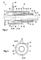
- FIGS. 2 and 3 a further embodiment is shown, in which as a drive element 18 a mounted on a dipping spindle 16 worm wheel 19 is formed. Trained as a spindle 16 shaft 15 is arranged along an axis 76.
- the support tube 14 has as in FIG. 1 a pot-shaped bearing receptacle 22 with a first axial bearing surface 21 on which the drive element 18 rests with a first axial stop 23.
- the second bearing plate 28 is formed as a sleeve with a circumferential collar 25, which serves as a second axial bearing surface 27 for a second stop 35 of the drive element 18.
- the drive element 18 and the bearing plate 28 are first preassembled in the support tube 14 and then fixed the bearing plate 28 in the support tube 14 such that the axial bearing clearance of the drive element 18 is suppressed.
- the sleeve-shaped bearing plate 28 is pressed with a predefined contact force 81 against the drive element 18 and the first bearing surface 21.
- the jacket portions 8 of the support tube 14 are pressed by a punch tool 85 radially inwardly, whereby an undercut 87 is formed, which bears axially with an axial end face 89 on the bearing plate 28.
- the end face 89 has a specific radial depth 91 and a certain width 95 over the circumference of the carrier tube 14. about the determination of the depth 91 bund the width 95 of the end face 89, and the number of material deformation 82, the transmission drive unit 10 can be adapted to the expected maximum axial forces 80.
- the bearing plate 28 has a central opening 67, which is penetrated by the spindle 16.
- the bearing plate 28 rests radially on the inner wall 70 over its entire axial extent and has an annular rear side 84.
- the end face 89 of the undercut 87 forms with the back 84, which is aligned approximately perpendicular to the shaft 15, an axial positive locking, which fixes the drive element 18 in the support tube 14 axially reliable.
- FIG. 4 shows a further embodiment of a transmission drive unit 10 according to the invention, in which the support tube 14 at one end 60 has a substantially closed bottom surface 92.
- a mounting opening 93 is formed to facilitate the reliable storage of the spindle 16 in the bearing plate 28.
- the bearing plate 28 is pre-assembled with the second molded axial bearing surface 27 and the drive element 18 in the support tube 14.
- a second separate bearing plate 28 is arranged with a pot-shaped bearing receptacle 22 in the support tube 14, which forms the first bearing surface 21.
- the first bearing surface 21 is fixed axially fixed in the support tube via the bearing plate 28.
- the bearing plate 28 with the second axial bearing surface 27 is now pressed axially with a biasing force 81 against the drive element 18, which is supported on the first bearing surface 21.
- the biasing force 81 is thereby introduced through the mounting opening 93 on the bearing plate 28.
- the jacket portions 8 of the support tube 14 are pressed radially inwardly, so that Stemmlaschen 94 are formed with a free end 97, which are each supported axially on the back 84 of the bearing plate 28.
- the bearing plate 28 is pressed axially fixed against the second stop 35 of the drive wheel 18, so this has no more play.
- a receptacle 52 for a fastening device 54 is formed directly, which is formed as a radial bore.
- the receptacle 52 represents a standard interface to the customer, which, however, can be modified by means of a recording module 90 into a customized, individual receptacle 88.
- the receiving module 90 is formed as an outer ring 64 which is arranged on the outer peripheral surface 66 of the support tube 14.
- the receiving module 90 has, for example, an internal thread 78 which engages in the externally threaded counter thread 79 of the carrier tube 14.
- the receiving module 90 covers the radial cutouts which are cut through the receptacle 52 and the caulking tabs 94 in the carrier tube 14.
- the receiving module 90 is in this embodiment simultaneously a support member 62, the strength of the support tube 14 at its End area 60 increased.
- the receiving module 90 has a receptacle 88 a cylindrical pin 96 which extends radially outwardly.
- This cylindrical bolt 96 corresponds to an integration of the fastening bolt 54 formed as a hinge pin 55 in FIG. 1 , With this receptacle 88, for example, the part 58 to be adjusted can be directly connected to the spindle drive 10 via eyes 86 formed thereon.
- the receiving module 90 the crash forces are transmitted securely from the adjustment part 58 on the support tube 14 and the spindle 16 and the threaded nut 98 on the body 99.
- the support tube 14 can be produced in different methods and have different concrete formations.
- the cross section of the support tube 14 is not limited to a circle.
- the support tube 14 may also be formed as a smooth cylinder tube, are arranged in the two separate bearing plates 28 for the storage of the spindle 16.
- the spindle 16 is preferably mounted on the drive element mounted thereon 18, but can be stored in a variation but also by means of bearing surfaces which are formed directly on the spindle 16.
- the torque transmission from the drive unit 42 is not limited to a worm gear 19, 39, but may for example also be transmitted by means of a spur gear.
- the concrete shape and material selection of material deformation 82 is selected according to the strength requirement, wherein one or more undercuts 87 or caulking tabs 94 can be pressed as needed.
- the size of the axial end face 89 can be selected according to their depth 91 and width 95, whereby the strength of the positive connection with the radially extending rear side 84 of the bearing plate 28 can be predetermined.
Abstract
Description
Die Erfindung betrifft eine Getriebe-Antriebseinheit mit einer axialspielfreien Lagerbefestigung insbesondere zum Verstellen eines beweglichen Teils im Kraftfahrzeug, nach Anspruch 1, und ein Verfahren zum Herstellen einer solchen Einheit nach Anspruch 13.The invention relates to a transmission drive unit with an axial play bearing mounting, in particular for adjusting a movable part in the motor vehicle, according to claim 1, and a method for producing such a unit according to claim 13.
Mit der
Die erfindungsgemäße Getriebe-Antriebseinheit und deren erfindungsgemäßes Herstellungsverfahren mit den Merkmalen der unabhängigen Ansprüche haben den Vorteil, dass durch die Anordnung des Antriebsrads der Spindel in einem Trägerrohr eine separate standardisierte Baugruppe geschaffen wird, die unabhängig ist von einem Getriebegehäuse oder dem Antriebsaggregat. Durch den Verzicht auf ein herkömmliches Getriebegehäuse, bei dem das Abtriebselement des Antriebsaggregats und das Antriebsrad der Spindel gemeinsam in einem geschlossenen Gehäuse angeordnet sind, kann die Getriebe-Antriebseinheit als modulares Baukastensystem sehr flexibel an unterschiedliche Befestigungsvorrichtungen der kundenspezifischen Anwendungen angepasst werden. Dabei kann immer die gleiche vormontierte Baugruppe mit dem Standard-Trägerrohr verwendet werden, wobei die mechanische Schnittstelle zur Befestigung der Getriebe-Antriebseinheit an der Karosserie oder an einem zu verstellenden Teil mittels eines kundenspezifischen Aufnahmemoduls für die Befestigungsvorrichtung nachträglich einfach variiert werden kann. Durch das Verformen des Wandmaterials des Trägerrohrs kann das Lagerschild sehr zuverlässig in einer definierten Position gehalten werden, nachdem zuvor das Axialspiel eliminiert wurde. Die Materialumformung des Trägerrohrs ermöglicht es, sehr hohe, auf das Antriebselement einwirkende axiale Kräfte auf das Trägerrohr abzuleiten.The transmission drive unit according to the invention and its inventive manufacturing method with the features of the independent claims have the advantage that a separate standardized assembly is provided by the arrangement of the drive wheel of the spindle in a support tube, which is independent of a transmission housing or the drive unit. By dispensing with a conventional transmission housing, in which the output element of the drive unit and the Drive wheel of the spindle are arranged together in a closed housing, the gear drive unit can be adapted as a modular system very flexible to different fastening devices of customer-specific applications. In this case, always the same preassembled module can be used with the standard support tube, wherein the mechanical interface for attaching the transmission drive unit to the body or to a part to be adjusted by means of a customer-specific module for the mounting device can be subsequently varied easily. By deforming the wall material of the support tube, the bearing plate can be held very reliably in a defined position, after previously the axial clearance has been eliminated. The material deformation of the support tube makes it possible to derive very high, acting on the drive element axial forces on the support tube.
Durch die in den Unteransprüchen aufgeführten Maßnahmen ergeben sich vorteilhafte Weiterbildungen und Verbesserungen der in den unabhängigen Ansprüchen angegebenen Merkmale. Wird das Mantelrohr radial nach innen gepresst, kann das Lagerschild praktisch unabhängig von der axialen Anpresskraft zur Längsspieleliminierung axial fixiert werden. Dabei wird die Lagerschildbefestigung nicht durch die fertigungsbedingten Toleranzen der zu lagernden Bauteile beeinflusst, wodurch das Lagerspiel zuverlässig unterbunden werden kann. Des Weiteren ist zur Lagerfixierung kein zusätzliches Bauteil notwendig, wodurch die Fertigung der Antriebseinheit kostengünstiger ist.The measures listed in the dependent claims, advantageous refinements and improvements of the features specified in the independent claims. If the jacket tube is pressed radially inward, the bearing plate can be axially fixed virtually independent of the axial contact pressure for Längstpielelimination. The bearing plate attachment is not affected by the manufacturing tolerances of the components to be stored, whereby the bearing clearance can be reliably prevented. Furthermore, no additional component is necessary for bearing fixation, whereby the production of the drive unit is less expensive.
Von Vorteil ist es, das Wandmaterial des Mantelbereichs radial derart einzudrücken, dass eine axiale Stirnfläche als Hinterschnitt gebildet wird, der am Lagerschild axial anliegt. Dabei kann in Abhängigkeit der auftretenden Axialkräfte die Breite und Tiefe des Hinterschnitts über die Stärke und Wirkungsdauer der Verstemmkraft variiert werden, ohne dass hierfür konstruktive Änderungen notwendig sind. Bildet der Hinterschnitt eine näherungsweise senkrecht zur Spindel ausgerichtete Stirnfläche, wird diese nur auf Scherung beansprucht, wodurch die Materialumformung auch bei hohen Axialkräften nicht in radialer Richtung zurückverformt werden kann. Dadurch wird ein Axialspiel wirksam unterbunden.It is advantageous to depress the wall material of the jacket region radially in such a way that an axial end face is formed as an undercut, which rests axially on the end shield. In this case, depending on the axial forces occurring, the width and depth of the undercut can be varied over the strength and duration of action of the caulking without the need for constructive changes are necessary. If the undercut forms an end face oriented approximately perpendicularly to the spindle, it is only subjected to shear, as a result of which the material deformation can not be deformed back in the radial direction, even at high axial forces. This effectively prevents axial play.
Durch die Anordnung der Mantelbereiche im Bereich des Trägerrohrs mit dem maximalen Durchmesser, lassen sich einfach mehrere Materialverformungen anbringen und deren Abmessungen leichter variieren. Außerdem wird durch den maximalen radialen Abstand zur Antriebsachse eine zuverlässigere Befestigung des Lagerschilds erzielt.The arrangement of the jacket areas in the region of the carrier tube with the maximum diameter, can easily attach more material deformations and their dimensions vary more easily. In addition, a more reliable attachment of the bearing plate is achieved by the maximum radial distance from the drive axle.
Wird das Wandmaterial des Trägerrohrs derart radial eingedrückt, dass sich eine Lasche mit einem freien Ende bildet, kann dieses freie Ende das Lagerschild zuverlässig axial fixieren.If the wall material of the support tube is pressed radially in such a way that a tab forms with a free end, this free end can reliably fix the end shield axially.
Verfahrenstechnisch kann das Wandmaterial besonders günstig mittels eines Verstemmwerkzeugs verformt werden, das radial auf die Mantelfläche des Trägerrohrs einwirkt. Dadurch kann ein Formschluss erzeugt werden, der das Lagerschild axial und gegebenenfalls auch in Umfangsrichtung fixiert.Technically, the wall material can be particularly advantageously deformed by means of a caulking, which acts radially on the outer surface of the support tube. Thereby, a positive connection can be generated, which fixes the bearing plate axially and possibly also in the circumferential direction.
Zur Minimierung der Reibung kann das Antriebselement besonders günstig näherungsweise punktförmig axial am Lagerschild gelagert werden. Dazu weist das axiale Ende des Antriebselements - insbesondere einer Drehspindel - als zweiten axialen Anschlag eine gewölbte Fläche auf, die beispielsweise als integrierte Kugel ausgebildet ist.In order to minimize the friction, the drive element can be mounted on the end shield in a particularly advantageous, approximately punctiform manner. For this purpose, the axial end of the drive element - in particular a rotary spindle - as a second axial stop on a curved surface, which is formed for example as an integrated ball.
In einer Variation der Erfindung weist hierzu das Lagerschild eine Anlauffläche in einem härteren Material auf, als der Rest des Lagerschilds. Diese harte Anlauffläche kann beispielsweise durch die Integration einer separat gefertigten Anlaufscheibe realisiert werden.In a variation of the invention for this purpose, the bearing plate has a contact surface in a harder material than the rest of the end shield. This hard contact surface can be realized for example by integrating a separately manufactured thrust washer.
Für die Anwendung einer durchtauchenden Spindel, die an beiden Seiten aus dem Trägerrohr ragt, kann das Antriebselement in einfacher Weise mittels eines umlaufenden Anschlagbunds axial gelagert werden, der am Lagerschild angeformt ist. Dabei liegt der Lagerbund radial möglichst nah an dem axialen Loch des Lagerschilds, durch das das Antriebselement bzw. die Welle durchgeführt ist.For the application of a dipping spindle, which protrudes on both sides of the support tube, the drive element can be stored axially in a simple manner by means of a circumferential stop collar, which is integrally formed on the bearing plate. In this case, the bearing collar is radially as close as possible to the axial hole of the bearing plate, through which the drive element or the shaft is performed.
Zur radialen Lagerung weist das Lagerschild eine hülsenförmige innere Mantelfläche auf, an dem das Antriebselement radial anliegt. Dadurch kann die axiale und radiale Lagerung vorteilhaft durch ein Bauteil realisiert werden.For radial mounting, the bearing plate has a sleeve-shaped inner circumferential surface on which the drive element bears radially. As a result, the axial and radial bearing advantageously be realized by a component.
Die erfindungsgemäße Lagerung des Antriebselements eignet sich besonders für ein Antriebsrad, das drehbar oder drehfest auf einer Welle gelagert ist. Hierbei kann die Welle direkt am Lagerschild anliegen, oder indirekt über das darauf gelagerte Antriebsrad sich am Lagerschild abstützen.The inventive mounting of the drive element is particularly suitable for a drive wheel which is rotatably or non-rotatably mounted on a shaft. Here, the shaft can rest directly on the bearing plate, or indirectly supported on the bearing thereon drive wheel on the bearing plate.
Ist die Getriebe-Antriebseinheit als Spindelantrieb ausgebildet, bei der die Welle eine Spindel ist, treten besonders hohe Axialkräfte auf. Diese können mittels der erfindungsgemäßen Materialumformung des Trägerrohrs zur Axialspieleliminierung besonders vorteilhaft aufgenommen werden.If the gear drive unit is designed as a spindle drive in which the shaft is a spindle, particularly high axial forces occur. These can be taken particularly advantageous by means of the material deformation of the support tube according to the invention for the elimination of axial play.
Das Trägerrohr ist günstiger Weise als Standard-Bauteil ausgebildet, in das als separate Baugruppe das Antriebsrad mit dem Lagerschild vormontiert werden. Dazu ist am Trägerrohr an einem Ende eine topfförmige Lageraufnahme ausgebildet, die die erste Lagerfläche für das Antriebselement bildet. Die Materialumformung wird dann am gegenüberliegenden Ende des Trägerrohrs mit dem größeren Durchmesser angeformt, an dem das eingefügte Lagerschild fixiert wird.The support tube is conveniently designed as a standard component, in which the drive wheel are pre-assembled with the end shield as a separate assembly. For this purpose, a pot-shaped bearing receptacle is formed on the support tube at one end, which forms the first bearing surface for the drive element. The material deformation is then formed at the opposite end of the carrier tube with the larger diameter at which the inserted bearing plate is fixed.
Das erfindungsgemäße Herstellungsverfahren nach dem unabhängigen Anspruch 13 hat den Vorteil, dass das Verstemmen des Mantelrohrs zur Ausbildung eines Formschlusses mit dem Lagerschild entkoppelt ist vom Einwirken der Vorhaltekraft auf das Lagerschild. Dadurch kann das Axialspiel unabhängig von Fertigungstoleranzen der einzelnen Bauteile zuverlässig unterbunden werden.The inventive manufacturing method according to the independent claim 13 has the advantage that the caulking of the jacket tube to form a positive connection with the bearing plate is decoupled from the action of the Vorhaltekraft on the bearing plate. As a result, the axial clearance can be reliably prevented regardless of manufacturing tolerances of the individual components.
Aufgrund des Verstemmprozesses kann die Lagerfixierung ohne zusätzlichen Aufwand an unterschiedliche Festigkeitsanforderungen bzw. unterschiedlichen einwirkenden Axialkräften sehr flexibel angepasst werden. Dies kann beispielsweise sehr einfach durch den radialen Vorschub des Stempelwerkzeugs gesteuert werden, wodurch sich ein unterschiedlich großer Hinterschnitt für die axiale Abstützung des Lagerschilds ergibt.Due to the Verstemmprozesses the bearing fixation can be adapted very flexibly without any additional effort to different strength requirements or different acting axial forces. This can be controlled for example very simply by the radial feed of the punch tool, resulting in a different sized undercut for the axial support of the bearing plate.
Das erfindungsgemäße Herstellungsverfahren ist auch auf eine Ausführung eines Trägerrohrs mit einer versteifenden Bodenfläche anwendbar, in der eine Montageöffnung ausgeformt ist. Nach dem Einbau des Lagerschilds und des Antriebsrads in das Trägerrohr kann durch die Montageöffnung eine Anpresskraft auf das Lagerschild ausgeübt werden, um das Lagerspiel zu eliminieren. Nach dem radialen Verstemmen der Mantelwand des Trägerrohrs ist das Lagerschild zuverlässig fixiert, sodass die bei der Montage aufgewendete Anpresskraft wieder entfernt werden kann.The manufacturing method according to the invention is also applicable to an embodiment of a carrier tube with a stiffening bottom surface, in which a mounting opening is formed. After installation of the bearing plate and the drive wheel in the support tube, a contact pressure force can be exerted on the bearing plate through the mounting hole to eliminate the bearing clearance. After the radial caulking of the jacket wall of the support tube, the bearing plate is reliably fixed so that the pressure applied during assembly contact pressure can be removed again.
In den Zeichnungen sind verschiedene Ausführungsbeispiele einer erfindungsgemäßen Getriebe-Antriebseinheit dargestellt und in der nachfolgenden Beschreibung näher erläutert. Es zeigen:
- Figur 1
- ein Schnitt durch eine erfindungsgemäße Getriebe-Antriebseinheit,
- Figur 2 und 3
- eine Schnittdarstellung und eine Ansicht eines weiteren Ausführungsbeispiels, und
- Figur 4
- einen Schnitt eines weiteren erfindungsgemäßen Spindelantriebs.
- FIG. 1
- a section through a transmission drive unit according to the invention,
- FIGS. 2 and 3
- a sectional view and a view of another embodiment, and
- FIG. 4
- a section of another spindle drive according to the invention.
Die in
Das Trägerrohr 14, das praktisch ein Gehäuse für die separate Baugruppe 12 bildet, weist des Weiteren eine Aufnahme 52 auf, in die eine Befestigungsvorrichtung 54 - beispielsweise ein Gelenkbolzen 55 - einschiebbar ist. Mit dieser Befestigungsvorrichtung 54 ist das Trägerrohr 14 beispielsweise gelenkig mit einem verstellenden Teil 58 im Kraftfahrzeug verbunden, beispielsweise ein nicht näher dargestellter Sitz oder ein Sitzteil, das gegenüber einem anderen Sitzteil verstellt wird. Zwischen der Aufnahme 52 und einem diesem näher liegenden Ende 60 des Trägerrohrs 14 ist ein Stützelement 62 am Trägerrohr 14 befestigt. Das Stützelement 62 ist als Außenring 64 ausgebildet, der in einer äußeren Umfangsfläche 66 des Trägerrohrs 14 anliegt. In der oberen Bildhälfte ist das Stützelement 62 beispielsweise mittels Schweißnähten 72 mit dem Trägerrohr 14 verbunden. Die untere Bildhälfte zeigt eine Befestigung des Stützelements 62 mittels einer Verstemmung 74 durch plastische Verformung. Bei einem Auffahrunfall tritt zwischen der Aufnahme 52 und dem Ende 60 des Trägerrohrs 14 eine hohe Materialbelastung auf. Diese erhöhten Kräfte werden durch das Stützelement 62 aufgenommen, das damit die zerstörungsfreie Kraftaufnahme des Trägerrohrs 14 erhöht. Dadurch bleibt das Spindelende 26 und damit das zu verstellende Teil 58 auch im Crash-Fall an seinem bestimmungsgemäßen Ort.The
Wirkt nun bei einem Verstellvorgang in axialer Richtung 76 eine Druckkraft 80 auf die Spindel 16 ein, wird die Welle 15 über das Antriebselement 18 in der topfförmigen Lageraufnahme 22 des Lagerschilds 28 abgestützt. Die Druckkraft 80 wird über das Lagerschild 28 auf die Materialumformung 82, und damit auf das Trägerrohr 14 übertragen, das sich wiederum an der auf die Befestigungsvorrichtung 54 abstützt.If a
In den
Im Trägerrohr 14 ist direkt eine Aufnahme 52 für eine Befestigungsvorrichtung 54 angeformt, die als radiale Bohrung ausgebildet ist. Hierbei stellt die Aufnahme 52 eine Standard-Schnittstelle zum Kunden dar, die jedoch mittels eines Aufnahmemoduls 90 in eine kundenspezifische, individuelle Aufnahme 88 abgeändert werden kann. Hierzu ist das Aufnahmemodul 90 als Außenring 64 ausgebildet, der auf der äußeren Umfangsfläche 66 des Trägerrohrs 14 angeordnet ist. Das Aufnahmemodul 90 weist beispielsweise ein Innengewinde 78 auf, das in das als Außengewinde ausgebildete Gegengewinde 79 des Trägerrohrs 14 greift. Das Aufnahmemodul 90 überdeckt die radialen Ausschnitte, die durch die Aufnahme 52 und die Verstemmlaschen 94 im Trägerrohr 14 eingeschnitten sind. Das Aufnahmemodul 90 stellt bei dieser Ausführung gleichzeitig ein Stützelement 62 dar, das die Festigkeit des Trägerrohrs 14 an dessen Endbereich 60 erhöht. Das Aufnahmemodul 90 weist als Aufnahme 88 einen zylindrischen Bolzen 96 auf, der sich radial nach außen erstreckt. Dieser zylindrische Bolzen 96 entspricht einer Integration des als Befestigungsvorrichtung 54 ausgebildeten Gelenkbolzen 55 in
Es sei angemerkt, dass hinsichtlich der in den Figuren gezeigten Ausführungsbeispiele und der Beschreibung vielfältige Kombinationsmöglichkeiten der einzelnen Merkmale untereinander möglich sind. So kann beispielsweise das Trägerrohr 14 in unterschiedlichen Verfahren hergestellt werden und unterschiedliche konkrete Ausformungen aufweisen. Der Querschnitt des Trägerrohrs 14 ist nicht auf einen Kreis beschränkt. Anstatt einer angeformten topfförmigen Lageraufnahme 22 kann das Trägerrohr 14 auch als glattes Zylinderrohr ausgebildet sein, in das zwei separate Lagerschilde 28 für die Lagerung der Spindel 16 angeordnet werden. Die Spindel 16 wird vorzugsweise über das darauf gelagerte Antriebselement 18 gelagert, kann in einer Variation aber auch mittels Lagerflächen gelagert werden, die direkt an der Spindel 16 angeformt sind. Die Momentübertragung vom Antriebsaggregat 42 ist nicht auf ein Schneckengetriebe 19, 39 beschränkt, sondern kann beispielsweise auch mittels eines Stirnradgetriebes übertragen werden. Die konkrete Form und Werkstoffauswahl der Materialumformung 82 wird entsprechend der Festigkeitsanforderung gewählt, wobei nach Bedarf ein oder mehrere Hinterschnitte 87 oder Verstemmlaschen 94 eingedrückt werden können. Ebenso kann die Größe der axialen Stirnfläche 89 über deren Tiefe 91 und Breite 95 entsprechend gewählt werden, wodurch die Stärke des Formschlusses mit der sich radial erstreckenden Rückseite 84 des Lagerschilds 28 vorgebbar ist.It should be noted that with regard to the exemplary embodiments and the description shown in the figures, a variety of possible combinations of the individual features are possible with one another. Thus, for example, the
Claims (15)
- Gearing/drive unit (10), in particular for adjusting a movable part (58) in a motor vehicle, having a drive element (18) which can be driven by means of a drive assembly (42) and which is rotatably mounted by means of at least one bearing shield (28) in a carrier tube (14), with the drive element (18) having a first axial stop (23) which is supported against a first axial bearing surface (21) of the carrier tube (14) and the drive element (18) having a second axial stop (35) which bears against a second axial bearing surface (27) of the bearing shield (28), with the bearing shield (28) being pressed by means of material deformation (82) of the carrier tube (14) against the second axial stop (35) of the drive element (18).
- Gearing/drive unit (10) according to Claim 1, characterized in that the material deformation (82) is formed by radially inwardly formed casing regions (8) of the carrier tube (14), with the casing regions (8) being arranged in particular in the region of a maximum diameter (6) of the carrier tube (14).
- Gearing/drive unit (10) according to Claim 2,
characterized in that the material deformation (82) of the casing region (8) is formed as an undercut (87) in which at least one pressed-in end surface (89) of the casing region (8) bears axially against the bearing shield (28) over a certain width (95) and a certain depth (91). - Gearing/drive unit (10) according to Claim 3, characterized in that the end surface (89) bears flush against a rear side (84) of the bearing shield (28), which rear side (84) extends approximately perpendicular to the axis (76) of the drive element (18).
- Gearing/drive unit (10) according to one of Claims 2-4, characterized in that the material deformation (82) of the casing region (8) is formed from at least one lug (94) with a free end (97) which bears axially against the bearing shield (28).
- Gearing/drive unit (10) according to one of the preceding claims, characterized in that the drive element (18) bears against the bearing shield (28) in a punctiform fashion - in particular by means of a spherical thrust portion (30).
- Gearing/drive unit (10) according to one of the preceding claims, characterized in that the drive element (18) bears axially against an encircling collar (25) of the bearing shield (28), which collar (25) in particular surrounds an axial hole (67), through which the drive unit (18) projects, of the bearing shield (28).
- Gearing/drive unit (10) according to one of the preceding claims, characterized in that the bearing shield (28) has an inner cylindrical lateral surface (37) which supports the drive element (18) radially.
- Gearing/drive unit (10) according to one of the preceding claims, characterized in that the bearing shield (28) has a thrust washer (32) which is formed from a harder material than the bearing shield (28).
- Gearing/drive unit (10) according to one of the preceding claims, characterized in that the drive element (18) is embodied as a worm gear (19) or spur gear which is arranged on a shaft (15).
- Gearing/drive unit (10) according to Claim 10, characterized in that the shaft (15) is embodied as a spindle (16) which in particular projects at both sides (20, 60) out of the carrier tube (14).
- Gearing/drive unit (10) according to one of Claims 10 or 11, characterized in that the first bearing surface (21) of the carrier tube (14) is formed as a pot-shaped bearing receptacle (22) with an axial opening (24) for the shaft (15), with the bearing receptacle (22) in particular being integrally formed in a unipartite fashion on the carrier tube (14) - preferably by means of a deep-drawing process.
- Method for producing a gearing/drive unit (10) according to one of the preceding claims, characterized by the following steps:- the drive element (18) and the bearing shield (28) are inserted into the carrier tube (14),- the bearing shield (28) is pressed with a defined preload force (81) axially against the drive element (18) such that the latter is supported against the first bearing surface (21) of the carrier tube (14),- the casing regions (8) of the carrier tube (14) are calked in the radial direction by means of a calking force (83) in order to generate a form-fitting action between the bearing shield (28) and the casing region (8) and to thereby fix the bearing shield (28).
- Method according to Claim 13, characterized in that the casing region (8) is pressed in radially to such an extent that an undercut (87) with an end surface (89) which extends approximately perpendicular to the carrier tube (14) is formed, which end surface (89) bears axially against the bearing shield (28) over a certain width (95) and a certain depth (91).
- Method according to one of Claims 13 or 14, characterized in that the carrier tube (14) has a base surface (92) with an assembly opening (93) through which the preload force (81) is imparted to the bearing shield (28) which is pre-mounted in the carrier tube (14).
Applications Claiming Priority (2)
| Application Number | Priority Date | Filing Date | Title |
|---|---|---|---|
| DE102005046354A DE102005046354A1 (en) | 2005-09-28 | 2005-09-28 | Transmission drive unit for use in e.g. motor vehicle, has drive component with axial stopper that lies at axial bearing surface of bearing bracket, which is pressed against axial stopper by material deformation of support pipe |
| PCT/EP2006/065282 WO2007036387A1 (en) | 2005-09-28 | 2006-08-14 | Transmission drive unit with a zero axial backlash bearing fastening, especially for adjusting a mobile part in the motor vehicle |
Publications (2)
| Publication Number | Publication Date |
|---|---|
| EP1931895A1 EP1931895A1 (en) | 2008-06-18 |
| EP1931895B1 true EP1931895B1 (en) | 2008-12-10 |
Family
ID=37053823
Family Applications (1)
| Application Number | Title | Priority Date | Filing Date |
|---|---|---|---|
| EP06792809A Not-in-force EP1931895B1 (en) | 2005-09-28 | 2006-08-14 | Transmission drive unit with a zero axial backlash bearing fastening, especially for adjusting a mobile part in the motor vehicle |
Country Status (10)
| Country | Link |
|---|---|
| US (1) | US8365630B2 (en) |
| EP (1) | EP1931895B1 (en) |
| JP (1) | JP4856710B2 (en) |
| KR (1) | KR101119481B1 (en) |
| CN (1) | CN101273222B (en) |
| AT (1) | ATE417217T1 (en) |
| DE (2) | DE102005046354A1 (en) |
| ES (1) | ES2316098T3 (en) |
| RU (1) | RU2404388C2 (en) |
| WO (1) | WO2007036387A1 (en) |
Cited By (1)
| Publication number | Priority date | Publication date | Assignee | Title |
|---|---|---|---|---|
| WO2013178243A1 (en) * | 2012-05-29 | 2013-12-05 | Husqvarna Ab | Rotation transfer arrangement |
Families Citing this family (14)
| Publication number | Priority date | Publication date | Assignee | Title |
|---|---|---|---|---|
| DE102006049808C5 (en) | 2006-10-17 | 2018-05-17 | Brose Fahrzeugteile Gmbh & Co. Kommanditgesellschaft, Coburg | Adjusting gear for an adjusting device |
| CN103392083B (en) * | 2011-02-28 | 2016-03-16 | C.劳勃.汉默斯坦两合有限公司 | The preparation method of adjusting driver and adjusting driver |
| US9074677B2 (en) * | 2011-03-14 | 2015-07-07 | Arvinmeritor Technology, Llc | Carrier assembly with threaded adjustment member |
| FR2977283B1 (en) * | 2011-06-28 | 2013-08-30 | Valeo Systemes Dessuyage | PERMANENT FASTENING SCREW |
| DE102012207129A1 (en) * | 2012-04-27 | 2013-10-31 | Robert Bosch Gmbh | Gear spindle and spindle gear, and method for producing a gear spindle |
| US9677608B2 (en) | 2013-11-13 | 2017-06-13 | Cnh Industrial America Llc | Agricultural rolling basket bearing assembly |
| FR3031562B1 (en) * | 2015-01-13 | 2017-01-27 | Hispano Suiza Sa | METHOD FOR MANUFACTURING A PROPELLER REDUCER |
| US10227872B2 (en) * | 2015-10-22 | 2019-03-12 | Nidec Motor Corporation | Internal bearing plate for gearmotor assembly |
| US10138936B2 (en) | 2016-12-13 | 2018-11-27 | Cnh Industrial America Llc | Agricultural rolling basket bearing assembly |
| ES2781191T3 (en) * | 2017-06-26 | 2020-08-31 | Flender Gmbh | Gear |
| RU2694002C2 (en) * | 2017-09-25 | 2019-07-08 | Федеральное государственное бюджетное образовательное учреждение высшего образования "Владимирский Государственный Университет имени Александра Григорьевича и Николая Григорьевича Столетовых" (ВлГУ) | Worm gearbox with reduction, elimination of backlash |
| DE202018105205U1 (en) * | 2018-09-11 | 2018-09-20 | Kuka Deutschland Gmbh | transmission |
| WO2020210517A1 (en) | 2019-04-12 | 2020-10-15 | Pacific Bearing Corp. | Axial anti-backlash stepper / servo motor |
| CN113137460A (en) * | 2021-04-18 | 2021-07-20 | 冯莉 | Regulation and control type mechanical alignment meshing structure |
Family Cites Families (37)
| Publication number | Priority date | Publication date | Assignee | Title |
|---|---|---|---|---|
| US2441640A (en) * | 1946-10-18 | 1948-05-18 | Miner Inc W H | Worm gear housing |
| US2781191A (en) * | 1953-02-12 | 1957-02-12 | Hupp Corp | Vehicle window regulator |
| US3202004A (en) * | 1961-05-19 | 1965-08-24 | Magna Corp | Reverse for worm drive, direct drive tiller |
| US3416386A (en) * | 1967-04-07 | 1968-12-17 | Ferro Mfg Corp | Threaded drive gear with abutment for screw shaft |
| US3463030A (en) * | 1968-05-06 | 1969-08-26 | Teledyne Inc | Anti-backlash gear reducer |
| DE1992617U (en) | 1968-05-29 | 1968-08-29 | Steinmueller Gmbh L & C | BURNERS FOR THE OPTIONAL COMBUSTION OF LIQUID AND / OR GASEOUS FUELS. |
| JPS4843667Y1 (en) * | 1970-01-22 | 1973-12-17 | ||
| IT950189B (en) * | 1972-03-15 | 1973-06-20 | Magneti Marelli Spa | DEVICE FOR DRIVING AND RE-TAKING THE AXIAL PLAY OF THE SCREWS OF THE SCREW REDUCERS WITHOUT END PARTICULARLY FOR SMALL POWER DUCTING MOTORS |
| US3811335A (en) * | 1973-04-25 | 1974-05-21 | Elevator Mfg Corp | Adjustable worm drive unit |
| JPS57139723A (en) | 1981-02-23 | 1982-08-28 | Olympus Optical Co Ltd | Automatic exposure controller of ttl direct measurement camera |
| JPS57139723U (en) * | 1981-02-25 | 1982-09-01 | ||
| JPS6221752A (en) | 1985-07-22 | 1987-01-30 | 昭和電工株式会社 | Manufacture of in2o3-sno2 sintered body |
| JPS6221752U (en) * | 1985-07-25 | 1987-02-09 | ||
| YU141885A (en) * | 1985-09-10 | 1988-10-31 | Viktor Zupancic | Worm gear reductor with connections |
| JPS62127545A (en) * | 1985-11-26 | 1987-06-09 | Aisin Seiki Co Ltd | Driving device for power sheet |
| JPS62165081A (en) | 1986-01-10 | 1987-07-21 | Takasago Thermal Eng Co Ltd | Producing method for valve |
| DE3815356A1 (en) * | 1988-05-05 | 1989-11-16 | Brose Fahrzeugteile | Worm gear for an adjustment drive in a motor vehicle, in particular a seat adjuster |
| JPH07106044B2 (en) * | 1990-11-16 | 1995-11-13 | マブチモーター株式会社 | Motor output shaft positioning device |
| DE4103202A1 (en) * | 1991-02-02 | 1992-08-06 | Lemfoerder Metallwaren Ag | STEERING COLUMN FOR MOTOR VEHICLES |
| JPH06249295A (en) * | 1993-02-25 | 1994-09-06 | Hiroshi Toyomasa | Drive transmitting device |
| DE19508306A1 (en) * | 1995-03-09 | 1996-09-12 | Bosch Gmbh Robert | Drive unit with an electric drive motor and a worm gear arranged downstream of it |
| JP3127112B2 (en) | 1995-04-11 | 2001-01-22 | 株式会社三協精機製作所 | Motor actuator |
| JP3653818B2 (en) * | 1995-09-22 | 2005-06-02 | アイシン精機株式会社 | Drive device |
| DE19537503A1 (en) * | 1995-09-26 | 1997-03-27 | Brose Fahrzeugteile | Controlling axial position of a rotating shaft |
| JPH10285861A (en) | 1997-04-08 | 1998-10-23 | Tokyo Parts Ind Co Ltd | Bearing device of small type dc motor and manufacture thereof |
| DE19844601A1 (en) * | 1998-09-29 | 2000-04-06 | Bosch Gmbh Robert | Electromotive drive device |
| DE19854535A1 (en) | 1998-11-26 | 2000-06-15 | Valeo Auto Electric Gmbh | Drive device, in particular for a windshield wiper system of a motor vehicle |
| JP3823600B2 (en) | 1999-04-23 | 2006-09-20 | 松下電工株式会社 | motor |
| DE19926171A1 (en) * | 1999-06-09 | 2000-12-14 | Bosch Gmbh Robert | Electric motor |
| JP4221825B2 (en) * | 1999-06-28 | 2009-02-12 | 株式会社ジェイテクト | Electric steering device |
| DE10005568A1 (en) * | 2000-02-09 | 2001-08-16 | Bosch Gmbh Robert | Spring element to compensate for axial play in a motor shaft of an electric motor |
| JP2002010564A (en) | 2000-06-21 | 2002-01-11 | Toshiba Tec Corp | Dc brushless motor |
| DE10042106A1 (en) * | 2000-08-26 | 2002-03-07 | Valeo Auto Electric Gmbh | driving device |
| JP4661014B2 (en) | 2001-02-13 | 2011-03-30 | 日本電産株式会社 | DYNAMIC PRESSURE BEARING DEVICE AND SPINDLE MOTOR HAVING THE DYNAMIC PRESSURE BEARING DEVICE |
| US6867516B2 (en) * | 2001-07-02 | 2005-03-15 | Valeo Motoren Und Aktuatoren Gmbh | Drive device with anti-lash mechanism |
| DE10250561A1 (en) * | 2002-10-30 | 2004-05-13 | Valeo Wischersysteme Gmbh | driving device |
| DE102004046094A1 (en) * | 2004-09-23 | 2006-04-06 | Robert Bosch Gmbh | Transmission drive unit with an adjustment |
-
2005
- 2005-09-28 DE DE102005046354A patent/DE102005046354A1/en not_active Withdrawn
-
2006
- 2006-08-14 CN CN2006800358212A patent/CN101273222B/en not_active Expired - Fee Related
- 2006-08-14 DE DE502006002349T patent/DE502006002349D1/en active Active
- 2006-08-14 RU RU2008116312/11A patent/RU2404388C2/en not_active IP Right Cessation
- 2006-08-14 AT AT06792809T patent/ATE417217T1/en not_active IP Right Cessation
- 2006-08-14 US US11/994,799 patent/US8365630B2/en not_active Expired - Fee Related
- 2006-08-14 KR KR1020087007598A patent/KR101119481B1/en not_active IP Right Cessation
- 2006-08-14 EP EP06792809A patent/EP1931895B1/en not_active Not-in-force
- 2006-08-14 WO PCT/EP2006/065282 patent/WO2007036387A1/en active Application Filing
- 2006-08-14 ES ES06792809T patent/ES2316098T3/en active Active
- 2006-08-14 JP JP2008532693A patent/JP4856710B2/en not_active Expired - Fee Related
Cited By (1)
| Publication number | Priority date | Publication date | Assignee | Title |
|---|---|---|---|---|
| WO2013178243A1 (en) * | 2012-05-29 | 2013-12-05 | Husqvarna Ab | Rotation transfer arrangement |
Also Published As
| Publication number | Publication date |
|---|---|
| EP1931895A1 (en) | 2008-06-18 |
| WO2007036387A1 (en) | 2007-04-05 |
| CN101273222A (en) | 2008-09-24 |
| DE502006002349D1 (en) | 2009-01-22 |
| DE102005046354A1 (en) | 2007-03-29 |
| RU2008116312A (en) | 2010-01-10 |
| US20080163712A1 (en) | 2008-07-10 |
| RU2404388C2 (en) | 2010-11-20 |
| ES2316098T3 (en) | 2009-04-01 |
| US8365630B2 (en) | 2013-02-05 |
| JP4856710B2 (en) | 2012-01-18 |
| ATE417217T1 (en) | 2008-12-15 |
| KR20080049079A (en) | 2008-06-03 |
| CN101273222B (en) | 2011-02-02 |
| JP2009510349A (en) | 2009-03-12 |
| KR101119481B1 (en) | 2012-06-14 |
Similar Documents
| Publication | Publication Date | Title |
|---|---|---|
| EP1931895B1 (en) | Transmission drive unit with a zero axial backlash bearing fastening, especially for adjusting a mobile part in the motor vehicle | |
| EP1987270B1 (en) | Spindle drive, in particular for adjusting a moveable part in a motor vehicle, and method for producing said spindle drive | |
| EP1931534B1 (en) | Transmission drive unit comprising a receiving module, especially for adjusting a mobile part in the motor vehicle | |
| EP1931532B1 (en) | Transmission drive unit comprising a support tube, and method for producing said drive unit | |
| EP1899565B1 (en) | Adapter and method for connecting an electric motor to a transmission interface of a bodywork part | |
| EP1797353B1 (en) | Method for producing a gearbox, and corresponding gearbox | |
| EP2478253A1 (en) | Device for vibration-damping mounting of a fluid assembly and associated fluid assembly | |
| WO2018019609A1 (en) | Drive device for a comfort drive of a motor vehicle, and comfort drive | |
| EP0918671A1 (en) | Electric drive unit | |
| DE102006009576A1 (en) | Spindle drive for adjusting a moving part in a motor vehicle comprises a spindle and a drive wheel that are built into the same support tube in a first installation position or in a second rotated installation position | |
| EP1789280A1 (en) | Gear/drive unit | |
| WO2013159968A1 (en) | Drive spindle and spindle drive and method for producing a drive spindle | |
| DE102012007329B4 (en) | Shaft-hub-connection | |
| WO2000005110A1 (en) | Tube plate for a wiper system | |
| EP2222498B1 (en) | Threaded spindle adjustment drive | |
| EP1579125B1 (en) | Gear transmission unit | |
| EP1794477B1 (en) | Gearbox drive unit comprising a regulating element | |
| WO2004057733A1 (en) | Drive unit for actuators in a motor vehicle | |
| DE10114453A1 (en) | Gearing and drive unit e.g. for automobile seat adjustment, has inner end of armature shaft supported in sleeve enclosed by one-piece damping element | |
| EP2090806B1 (en) | Transmission-drive unit with a bearing assembly | |
| EP1847728B1 (en) | Transmission-drive unit with a bolt and method for its manufacture | |
| DE102006020174A1 (en) | Gear unit with carrier pipe e.g. for adjusting motor vehicle seat, has spindle mounted drive wheel and which has output element and using power driver, drive wheel rotates in carrier tube which is mounted in recess | |
| EP2067652B1 (en) | Adapter element and adjustment drive with adapter element | |
| DE102010003188A1 (en) | Spindle drive i.e. plunging spindle drive, for adjustment device that is utilized by car seat, has bearings defining bearing axis that is formed at right angle from spindle to spindle axis, where spindle is arranged between bearings | |
| DE102004018684A1 (en) | Bolted connection for motor vehicle, has screw with long threaded bolt that is turned in through internal thread provided in socket of flange of engine mount till receiving thread of engine, for assembling engine and mount |
Legal Events
| Date | Code | Title | Description |
|---|---|---|---|
| PUAI | Public reference made under article 153(3) epc to a published international application that has entered the european phase |
Free format text: ORIGINAL CODE: 0009012 |
|
| 17P | Request for examination filed |
Effective date: 20080428 |
|
| AK | Designated contracting states |
Kind code of ref document: A1 Designated state(s): AT BE BG CH CY CZ DE DK EE ES FI FR GB GR HU IE IS IT LI LT LU LV MC NL PL PT RO SE SI SK TR |
|
| GRAP | Despatch of communication of intention to grant a patent |
Free format text: ORIGINAL CODE: EPIDOSNIGR1 |
|
| GRAS | Grant fee paid |
Free format text: ORIGINAL CODE: EPIDOSNIGR3 |
|
| GRAA | (expected) grant |
Free format text: ORIGINAL CODE: 0009210 |
|
| AK | Designated contracting states |
Kind code of ref document: B1 Designated state(s): AT BE BG CH CY CZ DE DK EE ES FI FR GB GR HU IE IS IT LI LT LU LV MC NL PL PT RO SE SI SK TR |
|
| REG | Reference to a national code |
Ref country code: GB Ref legal event code: FG4D Free format text: NOT ENGLISH |
|
| REG | Reference to a national code |
Ref country code: CH Ref legal event code: EP |
|
| REG | Reference to a national code |
Ref country code: IE Ref legal event code: FG4D Free format text: LANGUAGE OF EP DOCUMENT: GERMAN |
|
| REF | Corresponds to: |
Ref document number: 502006002349 Country of ref document: DE Date of ref document: 20090122 Kind code of ref document: P |
|
| REG | Reference to a national code |
Ref country code: ES Ref legal event code: FG2A Ref document number: 2316098 Country of ref document: ES Kind code of ref document: T3 |
|
| PG25 | Lapsed in a contracting state [announced via postgrant information from national office to epo] |
Ref country code: LT Free format text: LAPSE BECAUSE OF FAILURE TO SUBMIT A TRANSLATION OF THE DESCRIPTION OR TO PAY THE FEE WITHIN THE PRESCRIBED TIME-LIMIT Effective date: 20081210 |
|
| PG25 | Lapsed in a contracting state [announced via postgrant information from national office to epo] |
Ref country code: SI Free format text: LAPSE BECAUSE OF FAILURE TO SUBMIT A TRANSLATION OF THE DESCRIPTION OR TO PAY THE FEE WITHIN THE PRESCRIBED TIME-LIMIT Effective date: 20081210 Ref country code: PL Free format text: LAPSE BECAUSE OF FAILURE TO SUBMIT A TRANSLATION OF THE DESCRIPTION OR TO PAY THE FEE WITHIN THE PRESCRIBED TIME-LIMIT Effective date: 20081210 Ref country code: FI Free format text: LAPSE BECAUSE OF FAILURE TO SUBMIT A TRANSLATION OF THE DESCRIPTION OR TO PAY THE FEE WITHIN THE PRESCRIBED TIME-LIMIT Effective date: 20081210 Ref country code: LV Free format text: LAPSE BECAUSE OF FAILURE TO SUBMIT A TRANSLATION OF THE DESCRIPTION OR TO PAY THE FEE WITHIN THE PRESCRIBED TIME-LIMIT Effective date: 20081210 Ref country code: NL Free format text: LAPSE BECAUSE OF FAILURE TO SUBMIT A TRANSLATION OF THE DESCRIPTION OR TO PAY THE FEE WITHIN THE PRESCRIBED TIME-LIMIT Effective date: 20081210 |
|
| NLV1 | Nl: lapsed or annulled due to failure to fulfill the requirements of art. 29p and 29m of the patents act | ||
| REG | Reference to a national code |
Ref country code: HU Ref legal event code: AG4A Ref document number: E005153 Country of ref document: HU |
|
| REG | Reference to a national code |
Ref country code: IE Ref legal event code: FD4D |
|
| PG25 | Lapsed in a contracting state [announced via postgrant information from national office to epo] |
Ref country code: EE Free format text: LAPSE BECAUSE OF FAILURE TO SUBMIT A TRANSLATION OF THE DESCRIPTION OR TO PAY THE FEE WITHIN THE PRESCRIBED TIME-LIMIT Effective date: 20081210 Ref country code: RO Free format text: LAPSE BECAUSE OF FAILURE TO SUBMIT A TRANSLATION OF THE DESCRIPTION OR TO PAY THE FEE WITHIN THE PRESCRIBED TIME-LIMIT Effective date: 20081210 Ref country code: BG Free format text: LAPSE BECAUSE OF FAILURE TO SUBMIT A TRANSLATION OF THE DESCRIPTION OR TO PAY THE FEE WITHIN THE PRESCRIBED TIME-LIMIT Effective date: 20090310 Ref country code: IE Free format text: LAPSE BECAUSE OF FAILURE TO SUBMIT A TRANSLATION OF THE DESCRIPTION OR TO PAY THE FEE WITHIN THE PRESCRIBED TIME-LIMIT Effective date: 20081210 |
|
| PG25 | Lapsed in a contracting state [announced via postgrant information from national office to epo] |
Ref country code: PT Free format text: LAPSE BECAUSE OF FAILURE TO SUBMIT A TRANSLATION OF THE DESCRIPTION OR TO PAY THE FEE WITHIN THE PRESCRIBED TIME-LIMIT Effective date: 20090511 Ref country code: SE Free format text: LAPSE BECAUSE OF FAILURE TO SUBMIT A TRANSLATION OF THE DESCRIPTION OR TO PAY THE FEE WITHIN THE PRESCRIBED TIME-LIMIT Effective date: 20090310 Ref country code: IS Free format text: LAPSE BECAUSE OF FAILURE TO SUBMIT A TRANSLATION OF THE DESCRIPTION OR TO PAY THE FEE WITHIN THE PRESCRIBED TIME-LIMIT Effective date: 20090410 |
|
| PG25 | Lapsed in a contracting state [announced via postgrant information from national office to epo] |
Ref country code: SK Free format text: LAPSE BECAUSE OF FAILURE TO SUBMIT A TRANSLATION OF THE DESCRIPTION OR TO PAY THE FEE WITHIN THE PRESCRIBED TIME-LIMIT Effective date: 20081210 |
|
| PLBE | No opposition filed within time limit |
Free format text: ORIGINAL CODE: 0009261 |
|
| STAA | Information on the status of an ep patent application or granted ep patent |
Free format text: STATUS: NO OPPOSITION FILED WITHIN TIME LIMIT |
|
| PG25 | Lapsed in a contracting state [announced via postgrant information from national office to epo] |
Ref country code: DK Free format text: LAPSE BECAUSE OF FAILURE TO SUBMIT A TRANSLATION OF THE DESCRIPTION OR TO PAY THE FEE WITHIN THE PRESCRIBED TIME-LIMIT Effective date: 20081210 |
|
| 26N | No opposition filed |
Effective date: 20090911 |
|
| BERE | Be: lapsed |
Owner name: ROBERT BOSCH G.M.B.H. Effective date: 20090831 |
|
| PG25 | Lapsed in a contracting state [announced via postgrant information from national office to epo] |
Ref country code: MC Free format text: LAPSE BECAUSE OF NON-PAYMENT OF DUE FEES Effective date: 20090831 |
|
| PG25 | Lapsed in a contracting state [announced via postgrant information from national office to epo] |
Ref country code: BE Free format text: LAPSE BECAUSE OF NON-PAYMENT OF DUE FEES Effective date: 20090831 |
|
| PG25 | Lapsed in a contracting state [announced via postgrant information from national office to epo] |
Ref country code: GR Free format text: LAPSE BECAUSE OF FAILURE TO SUBMIT A TRANSLATION OF THE DESCRIPTION OR TO PAY THE FEE WITHIN THE PRESCRIBED TIME-LIMIT Effective date: 20090311 |
|
| PG25 | Lapsed in a contracting state [announced via postgrant information from national office to epo] |
Ref country code: AT Free format text: LAPSE BECAUSE OF NON-PAYMENT OF DUE FEES Effective date: 20090814 |
|
| REG | Reference to a national code |
Ref country code: CH Ref legal event code: PL |
|
| PG25 | Lapsed in a contracting state [announced via postgrant information from national office to epo] |
Ref country code: CH Free format text: LAPSE BECAUSE OF NON-PAYMENT OF DUE FEES Effective date: 20100831 Ref country code: LI Free format text: LAPSE BECAUSE OF NON-PAYMENT OF DUE FEES Effective date: 20100831 Ref country code: LU Free format text: LAPSE BECAUSE OF NON-PAYMENT OF DUE FEES Effective date: 20090814 |
|
| PG25 | Lapsed in a contracting state [announced via postgrant information from national office to epo] |
Ref country code: TR Free format text: LAPSE BECAUSE OF FAILURE TO SUBMIT A TRANSLATION OF THE DESCRIPTION OR TO PAY THE FEE WITHIN THE PRESCRIBED TIME-LIMIT Effective date: 20081210 |
|
| PG25 | Lapsed in a contracting state [announced via postgrant information from national office to epo] |
Ref country code: CY Free format text: LAPSE BECAUSE OF FAILURE TO SUBMIT A TRANSLATION OF THE DESCRIPTION OR TO PAY THE FEE WITHIN THE PRESCRIBED TIME-LIMIT Effective date: 20081210 |
|
| PGFP | Annual fee paid to national office [announced via postgrant information from national office to epo] |
Ref country code: HU Payment date: 20110809 Year of fee payment: 6 Ref country code: GB Payment date: 20110824 Year of fee payment: 6 Ref country code: ES Payment date: 20110825 Year of fee payment: 6 Ref country code: CZ Payment date: 20110801 Year of fee payment: 6 |
|
| GBPC | Gb: european patent ceased through non-payment of renewal fee |
Effective date: 20120814 |
|
| PG25 | Lapsed in a contracting state [announced via postgrant information from national office to epo] |
Ref country code: CZ Free format text: LAPSE BECAUSE OF NON-PAYMENT OF DUE FEES Effective date: 20120814 Ref country code: HU Free format text: LAPSE BECAUSE OF NON-PAYMENT OF DUE FEES Effective date: 20120815 |
|
| PG25 | Lapsed in a contracting state [announced via postgrant information from national office to epo] |
Ref country code: GB Free format text: LAPSE BECAUSE OF NON-PAYMENT OF DUE FEES Effective date: 20120814 |
|
| REG | Reference to a national code |
Ref country code: ES Ref legal event code: FD2A Effective date: 20131018 |
|
| PG25 | Lapsed in a contracting state [announced via postgrant information from national office to epo] |
Ref country code: ES Free format text: LAPSE BECAUSE OF NON-PAYMENT OF DUE FEES Effective date: 20120815 |
|
| REG | Reference to a national code |
Ref country code: FR Ref legal event code: PLFP Year of fee payment: 11 |
|
| REG | Reference to a national code |
Ref country code: FR Ref legal event code: PLFP Year of fee payment: 12 |
|
| PGFP | Annual fee paid to national office [announced via postgrant information from national office to epo] |
Ref country code: RO Payment date: 20170411 Year of fee payment: 7 |
|
| REG | Reference to a national code |
Ref country code: FR Ref legal event code: PLFP Year of fee payment: 13 |
|
| PG25 | Lapsed in a contracting state [announced via postgrant information from national office to epo] |
Ref country code: IT Free format text: LAPSE BECAUSE OF NON-PAYMENT OF DUE FEES Effective date: 20180814 |
|
| REG | Reference to a national code |
Ref country code: DE Ref legal event code: R084 Ref document number: 502006002349 Country of ref document: DE |
|
| PGFP | Annual fee paid to national office [announced via postgrant information from national office to epo] |
Ref country code: FR Payment date: 20200820 Year of fee payment: 15 |
|
| PGFP | Annual fee paid to national office [announced via postgrant information from national office to epo] |
Ref country code: DE Payment date: 20211025 Year of fee payment: 16 |
|
| PG25 | Lapsed in a contracting state [announced via postgrant information from national office to epo] |
Ref country code: FR Free format text: LAPSE BECAUSE OF NON-PAYMENT OF DUE FEES Effective date: 20210831 |
|
| REG | Reference to a national code |
Ref country code: DE Ref legal event code: R119 Ref document number: 502006002349 Country of ref document: DE |
|
| PG25 | Lapsed in a contracting state [announced via postgrant information from national office to epo] |
Ref country code: DE Free format text: LAPSE BECAUSE OF NON-PAYMENT OF DUE FEES Effective date: 20230301 |