EP1931069B1 - Procédé et système de synchronisation de signaux d'horloge - Google Patents
Procédé et système de synchronisation de signaux d'horloge Download PDFInfo
- Publication number
- EP1931069B1 EP1931069B1 EP07121473.8A EP07121473A EP1931069B1 EP 1931069 B1 EP1931069 B1 EP 1931069B1 EP 07121473 A EP07121473 A EP 07121473A EP 1931069 B1 EP1931069 B1 EP 1931069B1
- Authority
- EP
- European Patent Office
- Prior art keywords
- difference values
- value
- network element
- synchronizing
- fluctuation
- Prior art date
- Legal status (The legal status is an assumption and is not a legal conclusion. Google has not performed a legal analysis and makes no representation as to the accuracy of the status listed.)
- Not-in-force
Links
Images

Classifications
-
- H—ELECTRICITY
- H04—ELECTRIC COMMUNICATION TECHNIQUE
- H04J—MULTIPLEX COMMUNICATION
- H04J3/00—Time-division multiplex systems
- H04J3/02—Details
- H04J3/06—Synchronising arrangements
- H04J3/0635—Clock or time synchronisation in a network
- H04J3/0676—Mutual
-
- H—ELECTRICITY
- H04—ELECTRIC COMMUNICATION TECHNIQUE
- H04J—MULTIPLEX COMMUNICATION
- H04J3/00—Time-division multiplex systems
- H04J3/02—Details
- H04J3/06—Synchronising arrangements
- H04J3/0635—Clock or time synchronisation in a network
- H04J3/0638—Clock or time synchronisation among nodes; Internode synchronisation
- H04J3/0658—Clock or time synchronisation among packet nodes
- H04J3/0661—Clock or time synchronisation among packet nodes using timestamps
- H04J3/0664—Clock or time synchronisation among packet nodes using timestamps unidirectional timestamps
-
- H—ELECTRICITY
- H04—ELECTRIC COMMUNICATION TECHNIQUE
- H04L—TRANSMISSION OF DIGITAL INFORMATION, e.g. TELEGRAPHIC COMMUNICATION
- H04L7/00—Arrangements for synchronising receiver with transmitter
- H04L7/0008—Synchronisation information channels, e.g. clock distribution lines
- H04L7/0012—Synchronisation information channels, e.g. clock distribution lines by comparing receiver clock with transmitter clock
Definitions
- the invention relates to a method and system for mutually synchronizing a clock signal placed in the network element of a data network, and a clock signal placed in the network element of another data network.
- Said network elements can be for example routers or base stations of mobile phone networks.
- the synchronizing of clock signals is often based on that the network elements to be mutually synchronized transmit to each other synchronizing messages, on the basis of which each network element adjusts the operation frequency and/or phases of operation of its own clockwork.
- random-type element In many data networks, there is a remarkable random-type element in the transmission delays between the network elements, which random-type element complicates the adjusting process based on synchronizing messages and weakens the quality of the mutual synchronizing between the clock signals. Said random-type element is caused, among others, by random-type queuing delays experienced by the data to be transmitted in the transmission buffers and/or reception buffers of the network elements.
- the random-type nature of a transmission delay is strong particularly in packet, frame and cell switched data networks.
- this arrangement can be used for alleviating the effects of random-type queuing delays on the adjustment of a clock signal.
- the more heavily the data network is loaded the rarer are situations where the transmission buffers and/or reception buffers of a network element are empty or nearly empty.
- the shortest synchronizing message transmission delay that occurs during an observation period with a constant length all the more rarely represents a transmission delay that does not contain a random-type queuing delay.
- the random-type element of a transmission delay complicates the operation of an adjustment process based on synchronizing messages and weakens the quality of the mutual synchronizing between clock signals.
- the share of the random-type element in the shortest transmission delay occurring during the observation period can be decreased by extending the chronological length of the observation period.
- a chronological extension of the observation period also extends the chronological interval between successive adjusting measures, which complicates the adjusting process based on synchronizing messages and weakens the quality of the mutual synchronizing between clock signals.
- the publication WO 2005/077063 A2 introduces an arrangement where the adjusting effect of the information represented by a synchronizing message is attempted to be weighted according to how near the transmission delay experienced by said synchronizing message is to the transmission delay average value, type value, median value or low-pass filtered value.
- a method according to this arrangement leads to a better quality in the mutual synchronizing between clock signals than a conventional method based on averaging or low-pass filtering.
- a challenge is brought about by the effect of low-frequency components on the average value, type value, median value and low-pass filtered value of the transmission delay.
- the publication US2004264477 discloses a method for aligning clock domains over an asynchronous network between a source controlled by a first clock and a destination controlled by a second clock. An expected delay is estimated for transmitting packets between the source and the destination. Time-stamped synchronization packets are sent to the destination and each time-stamped synchronization packet carries timing information based on the first clock at the source. A set of synchronization packets are received at the destination to create a set of data points, and the set of data points is weighted so that synchronization packets exhibiting a delay further from the expected delay are accorded less weight than synchronization packets exhibiting a delay closer to the expected delay.
- the expected delay is updated to create an up-to-date estimate for the expected delay based on the set of data points taking into account the different weighting of the data points.
- a challenge is brought about by the effect of low-frequency components on the estimate of the expected delay.
- the publication US2002186681 discloses a method for reducing the effect of delay jitter in clock synchronization.
- the method comprises generating an error signal based on received data, filtering the error signal with a minimum delay filter, and controlling a clock with the filtered error signal.
- a time window is moved over the error signal. For each observation, such an error signal value that corresponds to a smallest transfer delay of all the error signal values in the time window is determined to be the output value of the filter. This process is repeated continuously as time progresses.
- a challenge is related to selection of a suitable temporal length for the time window so that the effect of the delay jitter is sufficiently suppressed, and, on the other hand, the operation of the clock control is not disturbed by too old error signal values.
- the invention relates to a system for mutually synchronizing a first clock signal placed in a first network element and a second clock signal placed in a second network element.
- Said first network element is arranged to transmit synchronizing messages to said second network element, and said second network element is arranged to receive said synchronizing messages.
- the system according to the invention includes:
- the invention also relates to a network element that is arranged to receive synchronizing messages and that includes:
- the invention also relates to a method for mutually synchronizing a first clock signal placed in a first network element and a second clock signal placed in a second network element, in which method:
- the invention also relates to a computer program for controlling a programmable processing unit in order to adjust a clock signal placed in a network element on the basis of the information contained by difference values corresponding to chronologically successive synchronizing messages.
- Each difference value is essentially the same as the difference of the reception time value and the transmission value of the received synchronizing message.
- Said reception time value depends on the cumulated number of periods of said clock signal at the moment of receiving said synchronizing message at a predetermined synchronizing point in said network element, and said transmission value depends on the position of said received synchronizing message in the chronological transmission order of the synchronizing messages.
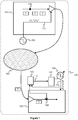
- Figure 1 illustrates a system according to an embodiment of the invention for mutually synchronizing a first clock signal 111 placed in a first network element 101 and a second clock signal 112 placed in a second network element 102 in a data network 100.
- the clock signal 111 is generated by an oscillator 103.
- the clock signal 112 is generated by an adjustable oscillator 104, which can be for example a numerically controlled oscillator NCO.
- the network element 101 is arranged to transmit synchronizing messages T to the network element 102, and the network element 102 is arranged to receive said synchronizing messages T.
- the system includes a calculation means 105, which is arranged to calculate the difference value 113 of the synchronizing message T, said difference value 113 being essentially the same as the difference of the reception time value and transmission value of said synchronizing message.
- Said reception time value depends on the cumulated number of periods of the clock signal 112 at the moment of arrival of said synchronizing message at a predetermined synchronizing point 108 in the network element 102.
- Said cumulated number of periods can be calculated for example by a calculator that is arranged to calculate the periods of the clock signal 112. Consequently, said cumulated number of periods corresponds to the moment of time data, i.e. to the clock time according to the clock signal 112.
- Said transmission value depends on the position of said synchronizing message in the chronological transmission order of the synchronizing messages.
- the synchronizing point 108 can be for instance an inlet port of a network element 102, in which case said reception time value corresponds to the moment of arrival of the synchronizing message in the network element 102.
- the system includes an adjusting means 107, which is arranged to adjust the clock signal 112 on the basis of the information contained by difference values 113 corresponding to chronologically successive synchronizing messages.
- the adjusting means 107 is arranged to weight the adjusting effect of the difference values 113 belonging to the first area of the margin of fluctuation of the difference values more heavily than the adjusting effect of the difference values belonging to the second area of said margin of fluctuation of the difference values. Said first area of the margin of fluctuation represents lower difference values than said second area of the margin of fluctuation.
- a network element 101 is arranged to transmit a first synchronizing message, to wait for a predetermined expected number of periods of the clock signal 111 and to transmit a second synchronizing message.
- a network element 102 is arranged to update the calculator value by a predetermined change value as a response to receiving said second synchronizing message.
- the calculation means 105 is arranged to use said calculator value as a transmission value connected to said synchronizing message.
- Said calculator value can be interpreted as the kind of information, the formation of which is based on previously known data.
- Said previously known data can for example express that the difference of the transmission times of chronologically successive synchronizing messages is constant.
- the clock signal 112 can be adjusted so that the ratio of the frequencies of the clock signals 112 and 111 remains constant as accurately as possible.
- Said constant value is not, however, known in the network element 102.
- the clock signal 112 can be adjusted so that the ratio of the frequencies of the clock signals 112 and 111 remains as accurately as possible at a predetermined constant value, which is essentially the ratio of the calculator change value and the number of the waiting periods of the clock signal 111.
- said ratio is one.
- the network element 101 is arranged to write in each synchronizing message a serial number or other data indicating the transmission order of the synchronizing messages.
- the network element 102 is better able to control situations, where the transmitted synchronizing message does not reach the network element 102, or where the arrival order of the synchronizing messages in the network element 102 is not the same as the transmission order of said synchronizing messages from the network element 101. Reversions in the order can happen for instance in a packet-switched data network without connections.
- the network element 101 is arranged to write in the synchronizing message a time stamp, which depends on the number of cumulated periods of the clock signal 111, which corresponds to the departure time of said synchronizing message from a predetermined synchronizing point 109 of the network element 101.
- the network element 102 is arranged to read said time stamp from said synchronizing message.
- the calculation means 105 is arranged to use said time stamp as a transmission value connected to said synchronizing message.
- the network element 102 can also use said time stamp as data indicating the transmission order of the synchronizing messages.
- the transmission value S k can be formed for example by means of a calculator in the network element 102, in case the network element 102 knows the differences P j of the transmission values on the basis of a rule known in advance. For instance the network element 101 can transmit the synchronizing messages at constant time slots, in which case Pj is constant with all values of j.
- S k can represent the time stamp to be written in the synchronizing message, which time stamp is written in the network element 101 of the synchronizing message T k .
- an increase in the difference value E would indicate a need to reduce the frequency f 112 of the clock signal 112, and respectively a decrease in the difference value E would indicate a need to increase the frequency f 112 of the clock signal 112.
- a fluctuation of the transmission delay D complicates the adjusting of the clock signal 112 and weakens the quality of the adjusting process, because the above mentioned resulting ratios are not necessarily valid with all k.
- the weakening of the adjusting quality is indicated for instance by an increase in the fluctuation of the frequency ratio f 112 /f 111 .
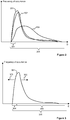
- Figure 2 illustrates the distributions of the transmission delays D, corresponding to the exemplary situations, in a system illustrated in Figure 1 .
- the sets JD1 and JD2 are assumed to be mutually deviant, but they can contain common elements.
- the routing topology and load situation of the data network 150 ( Figure 1 ) is assumed to be unchanged.
- the distributions 201 and 202 would be mutually similar, if the sets JD1 and JD2 would contain an infinite number of elements.
- the load of the data network 150 ( Figure 1 ) is larger than in an exemplary situation corresponding to the distributions 201 and 202.
- the distributions 201, 202 and 203 are best mutually resembling at the lower part 204 of the margin of fluctuation 205 of the transmission delay D, because transmission delays representing the lower part 204 of the margin of fluctuation of the transmission delay contain the least amount of random-type queuing delay.
- a moving average of the transmission delay D or a low-pass filtered value in the formation of which there are weighted transmission delays representing the lower part 204 of the margin of fluctuation of the transmission delay, generally remains better stable than a non-weighted moving average or a low-pass filtered value.
- Figure 3 illustrates the distribution of the difference values of the synchronizing messages corresponding to an exemplary situation in a system illustrated in Figure 1 .
- the distribution 301 has the same shape as the distribution of the corresponding transmission delays D n4 , D n4+1 , ..., D n4+m4 .
- the distribution 301 moves in the direction of the arrow 302.
- the distribution 301 moves in the direction of the arrow 303.
- the moving rate of the distribution of the difference values is so low that the distribution of the difference values is essentially of the same shape as the distribution of corresponding transmission delays.
- the moving average of the difference value E or a low-pass filtered value in the formation of which there is weighted the lower part 304 of the margin of fluctuation 306 of the difference values, generally remains better stable than a non-weighted moving average or low-pass filtered value.
- the adjusting means 107 ( Figure 1 ) is arranged to weight the adjusting effect of the difference values belonging to the first area 304 of the margin of fluctuation 306 more heavily than the adjusting effect of the difference values belonging to the second area 305 of the margin of fluctuation of said difference values.
- Said first area 304 of the margin of fluctuation represents smaller difference values than the second area 305 of said margin of fluctuation.
- the adjusting means 107 ( Figure 1 ) is arranged to define the limit value R, below which there is left a predetermined share of the difference values E. Said limit value can be used as a limit between the areas 304 and 305 ( Figure 3 ) of the margin of fluctuation 306 of the difference values.
- the adjusting means 107 ( Figure 1 ) is arranged to define said limit value R and to update said limit value R according to the following algorithm:
- the limit value R decreases, if too large a share of the difference values falls below the limit value R (r > p). Respectively the limit value R increases, if too small a share of the difference values falls below the limit value R (r ⁇ p).
- the rate of change of the limit value can be adjusted by means of a change step ⁇ . A suitable value for the change step ⁇ can be found for example by experimenting.
- the coefficient ⁇ is an adjusting step, by means of which the amplification of the adjusting process can be arranged. Fluctuation in the transmission delay D is in the adjusting of the clock signal 112 expressed as disturbing noise, the interfering effect of which can be alleviated by using a sufficiently small adjusting step ⁇ .
- the coefficient C 2 0.
- the adjusting means 107 is arranged to adjust the clock signal 112 only on the basis of the adjusting effect of difference values that are smaller than the limit value R.
- the adjusting means 107 ( Figure 1 ) is arranged to form a weighted moving average of the difference values, where the weighting coefficients of the difference values that fall below the limit value R are larger than the weighting coefficients of the difference values that surpass said limit value R, and to adjust the clock signal 112 on the basis of said weighted moving average.
- PLK k N, N+1, ...
- the adjusting means 107 is arranged to adjust the clock signal 112 only on the basis of adjusting effect of difference values that are smaller than the limit value R.
- the adjusting means 107 ( Figure 1 ) includes a low-pass filter that is arranged to form a low-pass filtered value of the difference values, where the weighting coefficients of difference values that fall below the limit value R are larger than the weighting coefficients of difference values that surpass said limit value R, and the adjusting means 107 is arranged to adjust the clock signal 112 on the basis of said low-pass filtered value.
- the adjusting means 107 is arranged to adjust the clock signal 112 only on the basis of the adjusting effect of difference values smaller than the limit value R.
- the adjusting means 107 ( Figure 1 ) is arranged to define the distribution estimate of the difference values and to update said distribution estimate of the difference values according to the following algorithm:
- the weighting coefficient C 2 used in the calculation of the weighted expected value POA k 0.
- the adjusting means 107 is arranged to adjust the clock signal 112 only on the basis of the adjusting effect of the difference values belonging to the interval Ha 1 ... Ha L+1 .
- the adjusting means 107 is arranged to form an estimate E min of the minimum difference value and to adjust the clock signal 112 on the basis of said estimate of the minimum difference value.
- the estimate of the minimum difference value can be defined for example according to the principle illustrated in Figure 4 .
- the difference value corresponding to the zero point 402 of the curve 401 represents said estimate E min of the minimum difference value.
- the curve 401 can be for instance a polynome that can be fitted with the values of the frequency of occurrence indicators, for example according to the shortest square sum method.
- a weighted moving average according to equation 10 can be used for instance as the input value the loop filter of a phase-locked loop that is arranged to adjust the frequency of the clock signal 112.
- the calculation means 105 and the adjusting means 107 illustrated in Figure 1 can be realized for instance by one or several programmable processors, application specific integrated circuits ASIC, field programmable gate arrays FPGA and/or memory circuits.
- FIG. 5 illustrates a network element 500 according to an embodiment of the invention.
- the network element includes a reception port 501, whereby the network element is arranged to receive synchronizing messages T.
- the network element is provided with calculation means 502 that is arranged to form the difference value 513 of the received synchronizing message, which is essentially the difference of the reception time value and the transmission value of said synchronizing message.
- Said reception time value depends on the cumulated number of periods of said clock signal 512 placed in the network element at the moment of arrival of said synchronizing message at a predetermined synchronizing point 508 in the network element.
- Said transmission value depends on the position of said synchronizing message in the chronological transmission order of the synchronizing messages.
- the network element comprises adjusting means 507 that is arranged to adjust the clock signal 512 on the basis of the information contained by difference values corresponding to chronologically successive synchronizing messages.
- the adjusting means 507 is arranged to weight the adjusting effect of the difference values belonging to the first area of the margin of fluctuation of said difference values more heavily than the adjusting effect of the difference values belonging to the second area of the margin of fluctuation of the difference values.
- the first area of said margin of fluctuation represents smaller difference values than said second area of the margin of fluctuation.
- the clock signal 512 is generated by an adjustable oscillator 504, which can be for instance a numerically controlled oscillator NCO.
- a network element is arranged to read the time stamp from the received synchronizing message, and the calculation means 502 is arranged to use said time stamp as the transmission value connected to said synchronizing message.
- a network element is arranged to update the calculator value by a predetermined number as a response to receiving a synchronizing message, and the calculation means 502 is arranged to use said calculator value as the transmission value connected to said synchronizing message.
- the adjusting means 507 is arranged to define a limit value that is not surpassed by a predetermined share of difference values.
- the adjusting means is arranged to form a weighted moving average of the difference values, where the weighting coefficients of the difference values that fall below said limit value are larger than the weighting coefficients of the difference values that surpass said limit value, and to adjust the clock signal 512 on the basis of said weighted moving average.
- the adjusting means 507 is arranged to define a limit value that is not surpassed by a predetermined share of difference values.
- the network element 500 includes a low-pass filter that is arranged to form a low-pass filtered value of said difference values, where the weighting coefficients of the difference values falling below said limit value are larger than the weighting coefficients of the difference values surpassing said limit value.
- the adjusting means 507 is arranged to adjust the clock signal 512 on the basis of said low-pass filtered value.
- the adjusting means 507 is arranged to define an estimate of the distribution of the difference values by classifying the difference values in value slots with predetermined low and high limits, and by forming for each value slot a frequency of occurrence indicator that is proportional to the number of the difference values belonging to said value slot.
- the adjusting means 507 is arranged to define the value slots that represent the lower part of said margin of fluctuation of the difference values, the sum of the frequency of occurrence indicators of said difference values being a predetermined share of the sum of the frequency of occurrence indicators of all value slots.
- the adjusting means 507 is arranged to calculate from said estimate of the distribution of the difference values a weighted expected value, where the weighting coefficients of the frequency of occurrence indicators of those value slots that represent the lower part of the margin of fluctuation of said difference values are larger than the weighting coefficients of the frequency of occurrence indicators of other value slots.
- the adjusting means 507 also is arranged to adjust the clock signal 512 on the basis of said weighted expected value.
- the adjusting means 507 is arranged to define the estimate of the distribution of the difference values by classifying said difference values in value slots that have predetermined low and high limits, and by forming for each value slot a frequency of occurrence indicator that is proportional to the number of the difference values belonging to said value slot.
- the adjusting means 507 is arranged to fit the curve with the frequency of occurrence indicators of the value slots representing said lower part of the margin of fluctuation of the difference values and to adjust the clock signal 512 on the basis of the difference value corresponding to the zero point of said curve.
- the network element illustrated in Figure 5 can be for example an IP (Internet Protocol) router, an ATM (Asynchronous Transfer Protocol) switch, an MPLS (Multi Protocol Label Switching) switch or an Ethernet switch, and it can serve for instance as a mobile phone base station.
- IP Internet Protocol
- ATM Asynchronous Transfer Protocol
- MPLS Multi Protocol Label Switching
- the block 510 illustrated in Figure 5 represents such parts in the network element that are not significant with respect to the present invention.
- the calculation means 502 and the adjusting means 507 illustrated in Figure 5 can be realized for example by one or several programmable processors, an application specific integrated circuit ASIC, a field programmable gate array FPGA, and/or a memory circuit.
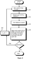
- FIG. 6 is a flowchart illustrating a method according to a preferred embodiment of the invention for mutually synchronizing a first clock signal CLK1 placed in a first network element V1 and a second clock signal CLK2 placed in a second network element V2.
- a synchronizing message T k is transmitted from a network element V1 to a network element V2.
- the synchronizing message T k is received in the network element V2.
- there is formed, for the synchronizing message T k a difference value E k that is essentially the difference of the reception time value and transmission value of the synchronizing message T k .
- Said reception time value depends on the cumulated number of periods of the clock signal CLK2 at the moment of arrival of the synchronizing message T k at a predetermined synchronizing point in the network element V2, and said transmission value depends on the position of the synchronizing message T k in the chronological transmission order of the synchronizing messages.
- the clock signal CLK2 is adjusted on the basis of the information contained by the difference value E k and at least one difference value corresponding to an earlier synchronizing message, so that in adjusting the clock signal CLK2, the adjusting effect of the difference values belonging to the first area of the margin of fluctuation of the difference values is weighted more heavily than the adjusting effect of the difference values belonging to the second area of the margin of fluctuation of the difference values.
- Said first and second area are selected so that the first area represents smaller difference values than the second area.
- the index k describing the passage of time is increased, and step 601 is resumed.
- a time stamp is written in the synchronizing message T k in the network element V1, said time stamp is read from the synchronizing message T k in the network element V2 and the time stamp is used as a transmission value connected to the synchronizing message T k .
- the time stamp depends on the cumulated number of periods of the clock signal CLK1, which number of periods corresponds to the moment of departure of the synchronizing message T k from a predetermined synchronizing point in the network element V1.
- a first synchronizing message is transmitted from the network element V1
- the system waits for a predetermined number of the waiting periods of the clock signal CLK1
- a second synchronizing message is transmitted from the network element V1
- the calculator value is updated by a predetermined change value as a response to receiving said second synchronizing message in the network element V2 and said calculator value is used as the transmission value connected to said second synchronizing message.
- the predetermined number of waiting periods is equal to the predetermined change value. Now the frequency of the clock signal CLK2 is attempted to be maintained the same as the frequency of the clock signal CLK1.
- a limit value that is not surpassed by a predetermined share of difference values, and there is formed a weighted moving average of said difference values, where the weighting coefficients of difference values that fall below said limit value are larger than the weighting coefficients of difference values that surpass said limit value.
- the clock signal CLK2 is adjusted on the basis of said weighted moving average.
- a limit value that is not surpassed by a predetermined share of difference values, and on the basis of said difference values, there is formed a low-pass filtered value, where the weighting coefficients of the difference values falling below said limit value are larger than the weighting coefficients of the difference values surpassing said limit value.
- the clock signal CLK2 is adjusted on the basis of said low-pass filtered value.
- an estimate of the distribution of the difference values by classifying said difference values in value slots having predetermined low and high limits, and by forming for each value slot a frequency of occurrence indicator that is proportional to the number of the difference values belonging to said value slots.
- an estimate of the distribution of the difference values by classifying said difference values in value slots having predetermined low and high limits, and by forming for each value slot a frequency of occurrence indicator that is proportional to the number of the difference values belonging to said value slots.
- a curve is fitted with the frequency of occurrence indicators of the value slots representing the lower part of the margin of fluctuation of the difference values.
- the clock signal CLK2 is adjusted on the basis of the difference value corresponding to the zero point of said curve.
- a computer program according to a preferred embodiment of the invention for controlling a programmable processing unit in order to adjust a clock signal placed in a network element comprises programwise means for controlling said programmable processing unit to weight the adjusting effect of the difference values belonging to the first area of the margin of fluctuation of the difference values more heavily than the adjusting effect of the difference values belonging to the second area of the margin of fluctuation of the difference values.
- Said first area represents smaller difference values than said second area.
- Each difference value is essentially the difference of the reception time value and transmission value of the received synchronizing message.
- Said reception time value depends on the cumulated number of periods of said clock signal at the moment of arrival of said received synchronizing message at a predetermined synchronizing point in said network element, and said transmission value depends on the position of said received synchronizing message in the chronological transmission order of synchronizing messages.
- Said program means can be for instance sub-programs or functions.
- a computer program according to a preferred embodiment of the invention is recorded in a storage device readable by the processing unit, such as an optical CD disk.
- a computer program according to an embodiment of the invention is coded in a signal that can be received in a data network such as the Internet.
Landscapes
- Engineering & Computer Science (AREA)
- Computer Networks & Wireless Communication (AREA)
- Signal Processing (AREA)
- Synchronisation In Digital Transmission Systems (AREA)
Claims (35)
- Système destiné à synchroniser mutuellement un premier signal d'horloge (111) placé dans un premier élément de réseau (101) et un second signal d'horloge (112) placé dans un second élément de réseau (102), ledit premier élément de réseau étant agencé de manière à transmettre des messages de synchronisation audit second élément de réseau, et ledit second élément de réseau étant agencé de manière à recevoir lesdits messages de synchronisation, ledit système comprenant :- un moyen de calcul (105) qui est agencé de manière à former une valeur de différence (113) d'un message de synchronisation, ladite valeur de différence correspondant essentiellement à une différence entre une valeur de temps de réception et une valeur de transmission du message de synchronisation, ladite valeur de temps de réception dépendant d'un nombre cumulé de périodes du second signal d'horloge à l'instant d'arrivée du message de synchronisation au niveau d'un point de synchronisation prédéterminé (108) dans le second élément de réseau, et ladite valeur de transmission dépendant d'une position dudit message de synchronisation dans un ordre de transmission chronologique des messages de synchronisation ; et- un moyen d'ajustement (107) qui est agencé de manière à ajuster le second signal d'horloge sur la base d'informations contenues par des valeurs de différence correspondant à des messages de synchronisation chronologiquement successifs ;caractérisé en ce que le moyen d'ajustement (107) est agencé de manière à :- déterminer une première zone (304) d'une marge de fluctuation (306) des valeurs de différence et une seconde zone (305) de la marge de fluctuation des valeurs de différence, de sorte que la première zone représente des valeurs de différence plus faibles que celles de la seconde zone, la première zone représente la partie la plus faible de la marge de fluctuation des valeurs de différence, et une part prédéterminée des valeurs de différence appartient à la première zone ; et- pondérer, lors de l'étape d'ajustement du second signal d'horloge sur la base des informations contenues par les valeurs de différence, les informations contenues par les valeurs de différence appartenant à la première zone de la marge de fluctuation des valeurs de différence, plus lourdement que les informations contenues par les valeurs de différence appartenant à la seconde zone de la marge de fluctuation des valeurs de différence.
- Système selon la revendication 1, caractérisé en ce que ledit premier élément de réseau est agencé de manière à écrire, dans ledit message de synchronisation, une estampille temporelle qui dépend d'un nombre cumulé de périodes du premier signal d'horloge, ledit nombre cumulé de périodes correspondant à un instant de départ dudit message de synchronisation à partir d'un point de synchronisation prédéterminé (109) dans ledit premier élément de réseau, dans lequel ledit second élément de réseau est agencé de manière à lire ladite estampille temporelle à partir dudit message de synchronisation, et ledit moyen de calcul est agencé de manière à utiliser ladite estampille temporelle en tant que ladite valeur de transmission.
- Système selon la revendication 1, caractérisé en ce que ledit premier élément de réseau est agencé de manière à transmettre un premier message de synchronisation, à attendre un premier nombre prédéterminé de périodes du premier signal d'horloge et à transmettre un second message de synchronisation, ledit second élément de réseau est agencé de manière à mettre à jour une valeur de calculateur, par un second nombre prédéterminé, en réponse à la réception du second message de synchronisation, et ledit moyen de calcul est agencé de manière à utiliser ladite valeur de calculateur en tant que ladite valeur de transmission.
- Système selon la revendication 3, caractérisé en ce que ledit premier nombre prédéterminé est égal audit second nombre prédéterminé.
- Système selon la revendication 1, caractérisé en ce que ledit moyen d'ajustement est agencé de manière à définir une valeur limite qui n'est pas dépassée par une part prédéterminée des valeurs de différence.
- Système selon la revendication 5, caractérisé en ce que ledit moyen d'ajustement est agencé de manière à former une moyenne mobile pondérée des valeurs de différence, où des coefficients de pondération des valeurs de différence qui se situent en dessous de ladite valeur limite sont supérieurs à des coefficients de pondération des valeurs de différence qui dépassent ladite valeur limite, et à ajuster le second signal d'horloge sur la base de ladite moyenne mobile pondérée.
- Système selon la revendication 5, caractérisé en ce que ledit moyen d'ajustement contient un filtre passe-bas qui est agencé de manière à former une valeur filtrée passe-bas des valeurs de différence, où des coefficients de pondération des valeurs de différence qui se situent en dessous de ladite valeur limite sont supérieurs à des coefficients de pondération des valeurs de différence qui dépassent ladite valeur limite, et en ce que ledit moyen d'ajustement est agencé de manière à ajuster le second signal d'horloge sur la base de ladite valeur filtrée passe-bas.
- Système selon la revendication 1, caractérisé en ce que ledit moyen d'ajustement est agencé de manière à définir une estimation d'une répartition des valeurs de différence en classant les valeurs de différence dans des fentes de valeurs (H1, H2, H3, H4) qui présentent des limites hautes et basses prédéterminées, et en formant, pour chaque fente de valeurs, une fréquence d'indicateur d'occurrences qui est proportionnelle à un nombre des valeurs de différence appartenant à ladite fente de valeurs.
- Système selon la revendication 8, caractérisé en ce que ledit moyen d'ajustement est agencé de manière à définir les fentes de valeurs représentant une partie inférieure de la marge de fluctuation des valeurs de différence, où la partie inférieure de la marge de fluctuation des valeurs de différence est telle qu'une somme de la fréquence d'indicateurs d'occurrences des fentes de valeurs représentant la partie inférieure de la marge de fluctuation des valeurs de différence correspond à une part prédéterminée d'une somme de la fréquence d'indicateurs d'occurrences de la totalité des fentes de valeurs, et en ce que ledit moyen d'ajustement est agencé de manière à calculer, à partir de ladite estimation de la répartition des valeurs de différence, une valeur pondérée attendue, où des coefficients de pondération de la fréquence d'indicateurs d'occurrences des fentes de valeurs représentant la partie inférieure de la marge de fluctuation des valeurs de différence sont supérieurs à des coefficients de pondération de la fréquence d'indicateurs d'occurrences d'autres fentes de valeurs, et en ce que ledit moyen d'ajustement est agencé de manière à ajuster le second signal d'horloge sur la base de ladite valeur pondérée attendue.
- Système selon la revendication 8, caractérisé en ce que ledit moyen d'ajustement est agencé de manière à ajuster une courbe (401) avec la fréquence d'indicateurs d'occurrences (403, 404, 405) des fentes de valeurs représentant une partie inférieure de la marge de fluctuation des valeurs de différence, et à ajuster le second signal d'horloge sur la base de la valeur de différence correspondant à un point nul (402) de ladite courbe.
- Élément de réseau (500) qui est agencé de manière à recevoir des messages de synchronisation, et qui comporte :- un moyen de calcul (502) qui est agencé de manière à former une valeur de différence (513) d'un message de synchronisation reçu, ladite valeur de différence correspondant essentiellement à une différence entre une valeur de temps de réception et une valeur de transmission dudit message de synchronisation, ladite valeur de temps de réception dépendant d'un nombre cumulé de périodes d'un signal d'horloge (512) placé dans ledit élément de réseau à un instant d'arrivée dudit message de synchronisation au niveau d'un point de synchronisation prédéterminé (508) dans ledit élément de réseau, et ladite valeur de transmission dépendant d'une position dudit message de synchronisation dans un ordre de transmission chronologique des messages de synchronisation ; et- un moyen d'ajustement (507) qui est agencé de manière à ajuster ledit signal d'horloge sur la base d'informations contenues par des valeurs de différence correspondant à des messages de synchronisation chronologiquement successifs ;caractérisé en ce que le moyen d'ajustement est agencé de manière à :- déterminer une première zone (304) d'une marge de fluctuation (306) des valeurs de différence et une seconde zone (305) de la marge de fluctuation des valeurs de différence, de sorte que la première zone représente des valeurs de différence plus faibles que celles de la seconde zone, la première zone représente la partie la plus faible de la marge de fluctuation des valeurs de différence, et une part prédéterminée des valeurs de différence appartient à la première zone ; et- pondérer, lors de l'étape d'ajustement du signal d'horloge sur la base des informations contenues par les valeurs de différence, les informations contenues par les valeurs de différence appartenant à la première zone de la marge de fluctuation des valeurs de différence, plus lourdement que les informations contenues par les valeurs de différence appartenant à la seconde zone de la marge de fluctuation des valeurs de différence.
- Élément de réseau selon la revendication 11, caractérisé en ce que ledit élément de réseau est agencé de manière à lire une estampille temporelle à partir dudit message de synchronisation, et en ce que ledit moyen de calcul est agencé de manière à utiliser ladite estampille temporelle en tant que ladite valeur de transmission.
- Élément de réseau selon la revendication 11, caractérisé en ce que ledit élément de réseau est agencé de manière à mettre à jour une valeur de calculateur, par un nombre prédéterminé, en réponse à la réception dudit message de synchronisation, et en ce que ledit moyen de calcul est agencé de manière à utiliser ladite valeur de calculateur en tant que ladite valeur de transmission.
- Élément de réseau selon la revendication 11, caractérisé en ce que ledit moyen d'ajustement est agencé de manière à définir une valeur limite qui n'est pas dépassée par une part prédéterminée des valeurs de différence.
- Élément de réseau selon la revendication 14, caractérisé en ce que ledit moyen d'ajustement est agencé de manière à former une moyenne mobile pondérée des valeurs de différence, où des coefficients de pondération des valeurs de différence qui se situent en dessous de ladite valeur limite sont supérieurs à des coefficients de pondération des valeurs de différence qui dépassent ladite valeur limite, et à ajuster ledit signal d'horloge sur la base de ladite moyenne mobile pondérée.
- Élément de réseau selon la revendication 14, caractérisé en ce que ledit moyen d'ajustement inclut un filtre passe-bas qui est agencé de manière à former une valeur filtrée passe-bas des valeurs de différence, où des coefficients de pondération des valeurs de différence qui se situent en dessous de ladite valeur limite sont supérieurs à des coefficients de pondération des valeurs de différence qui dépassent ladite valeur limite, et en ce que ledit moyen d'ajustement est agencé de manière à ajuster ledit signal d'horloge sur la base de ladite valeur filtrée passe-bas.
- Élément de réseau selon la revendication 11, caractérisé en ce que ledit moyen d'ajustement est agencé de manière à définir une estimation de la répartition des valeurs de différence, en classant lesdites valeurs de différence dans des fentes de valeurs qui présentent des limites hautes et basses prédéterminées, et en formant, pour chaque fente de valeurs, une fréquence d'indicateur d'occurrences qui est proportionnelle à un nombre des valeurs de différence appartenant à ladite fente de valeurs.
- Élément de réseau selon la revendication 17, caractérisé en ce que ledit moyen d'ajustement est agencé de manière à définir les fentes de valeurs représentant une partie inférieure de ladite marge de fluctuation des valeurs de différence, où la partie inférieure de la marge de fluctuation des valeurs de différence est telle qu'une somme de la fréquence d'indicateurs d'occurrences des fentes de valeurs représentant la partie inférieure de la marge de fluctuation des valeurs de différence correspond à une part prédéterminée d'une somme de la fréquence d'indicateurs d'occurrences de la totalité des fentes de valeurs, et en ce que ledit moyen d'ajustement est agencé de manière à calculer une valeur pondérée attendue, à partir de ladite estimation de la répartition de valeurs de différence, où des coefficients de pondération de la fréquence d'indicateurs d'occurrences de ces fentes de valeurs qui représentent la partie inférieure de la marge de fluctuation des valeurs de différence sont supérieurs à des coefficients de pondération de la fréquence d'indicateurs d'occurrences d'autres fentes de valeurs, et en ce que ledit moyen d'ajustement est agencé de manière à ajuster ledit signal d'horloge sur la base de ladite valeur pondérée attendue.
- Élément de réseau selon la revendication 17, caractérisé en ce que ledit moyen d'ajustement est agencé de manière à ajuster une courbe (401) avec la fréquence d'indicateurs d'occurrences (403, 404, 405) des fentes de valeurs représentant une partie inférieure de ladite marge de fluctuation des valeurs de différence, et à ajuster ledit signal d'horloge sur la base de la valeur de différence correspondant à un point nul (402) de ladite courbe.
- Élément de réseau selon la revendication 11, caractérisé en ce que l'élément de réseau est l'un des éléments suivants :un routeur IP (protocole Internet) et un commutateur MPLS (commutation multiprotocole par étiquette).
- Élément de réseau selon la revendication 11, caractérisé en ce que l'élément de réseau est un commutateur Ethernet.
- Élément de réseau selon la revendication 11, caractérisé en ce que l'élément de réseau est une station de base de réseau de téléphonie mobile.
- Procédé de synchronisation mutuelle d'un premier signal d'horloge placé dans un premier élément de réseau et d'un second signal d'horloge placé dans un second élément de réseau, le procédé comprenant les étapes ci-dessous consistant à :- transmettre (601) des messages de synchronisation du premier élément de réseau au second élément de réseau ;- recevoir (602) lesdits messages de synchronisation dans ledit second élément de réseau ;- pour chaque message de synchronisation, former (603) une valeur de différence qui correspond essentiellement à une différence entre une valeur de temps de réception et une valeur de transmission dudit message de synchronisation, ladite valeur de temps de réception dépendant d'un nombre cumulé de périodes du second signal d'horloge placé dans ledit second élément de réseau à un instant d'arrivée dudit message de synchronisation au niveau d'un point de synchronisation prédéterminé dans ledit second élément de réseau, et ladite valeur de transmission dépendant d'une position dudit message de synchronisation dans un ordre de transmission chronologique des messages de synchronisation ; et- ajuster (604) ledit second signal d'horloge sur la base d'informations contenues par des valeurs de différence correspondant à des messages de synchronisation chronologiquement successifs ;caractérisé en ce que le procédé comprend en outre les étapes ci-dessous consistant à :- déterminer une première zone (304) d'une marge de fluctuation (306) des valeurs de différence et une seconde zone (305) de la marge de fluctuation des valeurs de différence, de sorte que la première zone représente des valeurs de différence plus faibles que celles de la seconde zone, la première zone représente la partie la plus faible de la marge de fluctuation des valeurs de différence, et une part prédéterminée des valeurs de différence appartient à la première zone ; et- pondérer, lors de l'étape d'ajustement (604) dudit second signal d'horloge sur la base des informations contenues par les valeurs de différence, les informations contenues par les valeurs de différence appartenant à la première zone de la marge de fluctuation des valeurs de différence, plus lourdement que les informations contenues par les valeurs de différence appartenant à la seconde zone de la marge de fluctuation des valeurs de différence.
- Procédé selon la revendication 23, caractérisé en ce qu'une estampille temporelle est écrite dans ledit message de synchronisation, ladite estampille temporelle dépendant d'un nombre cumulé de périodes du premier signal d'horloge, ledit nombre cumulé de périodes correspondant à un instant de départ dudit message de synchronisation à partir d'un point de synchronisation prédéterminé dans le premier élément de réseau, ladite estampille temporelle est lue à partir dudit message de synchronisation, et l'estampille temporelle est utilisée en tant que ladite valeur de transmission.
- Procédé selon la revendication 23, caractérisé en ce qu'un premier message de synchronisation est transmis à partir d'un premier élément de réseau, le système attend un premier nombre prédéterminé de périodes du premier signal d'horloge, un second message de synchronisation est transmis à partir du premier élément de réseau, une valeur de calculateur est mise à jour, par un second nombre prédéterminé, en réponse à la réception du second message de synchronisation dans un second élément de réseau, et ladite valeur de calculateur est utilisée en tant que la valeur de transmission associée audit second message de synchronisation.
- Procédé selon la revendication 25, caractérisé en ce que ledit premier nombre prédéterminé est égal audit second nombre prédéterminé.
- Procédé selon la revendication 23, caractérisé en ce qu'est définie une valeur limite qui n'est pas dépassée par une part prédéterminée des valeurs de différence.
- Procédé selon la revendication 27, caractérisé en ce qu'est formée une moyenne mobile pondérée des valeurs de différence, où des coefficients de pondération des valeurs de différence qui se situent en dessous de ladite valeur limite sont supérieurs à des coefficients de pondération des valeurs de différence qui surpassent ladite valeur limite, et en ce que ledit second signal d'horloge est ajusté sur la base de ladite moyenne mobile pondérée.
- Procédé selon la revendication 27, caractérisé en ce qu'est formée une valeur filtrée passe-bas des valeurs de différence, où des coefficients de pondération des valeurs de différence qui se situent en dessous de ladite valeur limite sont supérieurs à des coefficients de pondération des valeurs de différence qui surpassent ladite valeur limite, et en ce que ledit second signal d'horloge est ajusté sur la base de ladite valeur filtrée passe-bas.
- Procédé selon la revendication 23, caractérisé en ce qu'est définie une estimation d'une répartition des valeurs de différence, en classant les valeurs de différence dans des fentes de valeurs avec des limites hautes et basses prédéterminées, et en formant, pour chaque fente de valeurs, une fréquence d'indicateur d'occurrences qui est proportionnelle à un nombre de valeurs de différence appartenant auxdites fentes de valeurs.
- Procédé selon la revendication 30, caractérisé en ce que le procédé comprend l'étape consistant à déterminer des fentes de valeurs représentant une partie inférieure de la marge de fluctuation des valeurs de différence, où la partie inférieure de la marge de fluctuation des valeurs de différence est telle qu'une somme de la fréquence d'indicateurs d'occurrences des fentes de valeurs représentant la partie inférieure de la marge de fluctuation des valeurs de différence correspond à une part prédéterminée d'une somme de la fréquence d'indicateurs d'occurrences de la totalité des fentes de valeurs, et en ce que le procédé comprend l'étape consistant à calculer, à partir de ladite estimation de la répartition des valeurs de différence, une valeur pondérée attendue, où des coefficients de pondération de la fréquence d'indicateurs d'occurrences desdites fentes de valeurs représentant ladite partie inférieure de la marge de fluctuation des valeurs de différence sont supérieurs à des coefficients de pondération de la fréquence d'indicateurs d'occurrences d'autres fentes de valeurs, et en ce que le procédé comprend l'étape consistant à ajuster le second signal d'horloge sur la base de ladite valeur pondérée attendue.
- Procédé selon la revendication 30, caractérisé en ce qu'une courbe (401) est adaptée avec la fréquence d'indicateurs d'occurrences (403, 404, 405) des fentes de valeurs représentant une partie inférieure de la marge de fluctuation des valeurs de différence, et en ce que ledit second signal d'horloge est ajusté sur la base de la valeur de différence correspondant au point nul (402) de ladite courbe.
- Programme informatique pour commander à une unité de traitement programmable d'ajuster un signal d'horloge placé dans un élément de réseau, sur la base d'informations contenues par des valeurs de différence correspondant à des messages de synchronisation chronologiquement successifs, chacune desdites valeurs de différence correspondant essentiellement à une différence entre une valeur de temps de réception et une valeur de transmission d'un message de synchronisation reçu, ladite valeur de temps de réception dépendant d'un nombre cumulé de périodes dudit signal d'horloge à l'instant d'arrivée dudit message de synchronisation reçu au niveau d'un point de synchronisation prédéterminé dans ledit élément de réseau, et ladite valeur de transmission dépendant d'une position dudit message de synchronisation reçu dans un ordre de transmission chronologique des messages de synchronisation, caractérisé en ce que le programme informatique est doté d'un moyen de programme informatique pour commander à ladite unité de traitement programmable de :- déterminer une première zone (304) d'une marge de fluctuation (306) des valeurs de différence et une seconde zone (305) de la marge de fluctuation des valeurs de différence, de sorte que la première zone représente des valeurs de différence plus faibles que celles de la seconde zone, la première zone représente la partie la plus faible de la marge de fluctuation des valeurs de différence, et une part prédéterminée des valeurs de différence appartient à la première zone ; et- pondérer, lors de l'étape d'ajustement du signal d'horloge sur la base des informations contenues par les valeurs de différence, les informations contenues par les valeurs de différence appartenant à la première zone de la marge de fluctuation des valeurs de différence, plus lourdement que les informations contenues par les valeurs de différence appartenant à la seconde zone de la marge de fluctuation des valeurs de différence.
- Programme informatique selon la revendication 33, caractérisé en ce que le programme informatique est enregistré sur un disque optique.
- Programme informatique selon la revendication 33, caractérisé en ce que le programme informatique est codé dans un signal qui peut être reçu à partir d'un réseau de données.
Applications Claiming Priority (1)
| Application Number | Priority Date | Filing Date | Title |
|---|---|---|---|
| FI20061068A FI119165B (fi) | 2006-12-04 | 2006-12-04 | Menetelmä ja järjestelmä kellosignaalien tahdistamiseksi |
Publications (3)
| Publication Number | Publication Date |
|---|---|
| EP1931069A2 EP1931069A2 (fr) | 2008-06-11 |
| EP1931069A3 EP1931069A3 (fr) | 2010-12-22 |
| EP1931069B1 true EP1931069B1 (fr) | 2017-01-04 |
Family
ID=37623705
Family Applications (1)
| Application Number | Title | Priority Date | Filing Date |
|---|---|---|---|
| EP07121473.8A Not-in-force EP1931069B1 (fr) | 2006-12-04 | 2007-11-26 | Procédé et système de synchronisation de signaux d'horloge |
Country Status (4)
| Country | Link |
|---|---|
| US (1) | US7995623B2 (fr) |
| EP (1) | EP1931069B1 (fr) |
| CN (1) | CN101197632A (fr) |
| FI (1) | FI119165B (fr) |
Families Citing this family (7)
| Publication number | Priority date | Publication date | Assignee | Title |
|---|---|---|---|---|
| DE102010022525A1 (de) * | 2010-02-11 | 2012-05-10 | Siemens Aktiengesellschaft | Verfahren zur Zeitsynchronisation in einem Kommunikationsnetz |
| FI123505B (fi) | 2011-03-14 | 2013-06-14 | Tellabs Oy | Menetelmä ja laite kellosignaalilähteen ohjaamiseksi |
| CN103427927B (zh) * | 2012-05-17 | 2017-04-12 | 中兴通讯股份有限公司 | Mpls‑tp网络实现时钟同步的方法及装置 |
| JP6982510B2 (ja) * | 2018-01-26 | 2021-12-17 | セイコーソリューションズ株式会社 | 時刻配信装置、および時刻調整方法 |
| JP7332690B2 (ja) * | 2019-05-31 | 2023-08-23 | 株式会社東芝 | コミュニケーション管理装置 |
| US11516151B2 (en) | 2019-12-31 | 2022-11-29 | Infinera Oy | Dynamically switching queueing systems for network switches |
| WO2021223834A1 (fr) | 2020-05-04 | 2021-11-11 | Huawei Technologies Co., Ltd. | Réglage de synchronisation sans fil pour trafic périodique de multiples domaines temporels |
Family Cites Families (15)
| Publication number | Priority date | Publication date | Assignee | Title |
|---|---|---|---|---|
| JPS4943809B1 (fr) * | 1968-10-25 | 1974-11-25 | ||
| SE507227C2 (sv) * | 1996-09-16 | 1998-04-27 | Ericsson Telefon Ab L M | Metod och anordning för synkronisering av tidsstämpling |
| US6292490B1 (en) * | 1998-01-14 | 2001-09-18 | Skystream Corporation | Receipts and dispatch timing of transport packets in a video program bearing stream remultiplexer |
| US6111896A (en) * | 1998-01-14 | 2000-08-29 | Skystream Corporation | Remultiplexer for video program bearing transport streams with program clock reference time stamp adjustment |
| US6246701B1 (en) * | 1998-01-14 | 2001-06-12 | Skystream Corporation | Reference time clock locking in a remultiplexer for video program bearing transport streams |
| US6195368B1 (en) * | 1998-01-14 | 2001-02-27 | Skystream Corporation | Re-timing of video program bearing streams transmitted by an asynchronous communication link |
| US6704329B2 (en) * | 2001-05-08 | 2004-03-09 | Path 1 Network Technologies Inc. | Minimizing the effect of jitter upon the quality of service operation of networked gateway devices |
| EP1283611A3 (fr) | 2001-08-09 | 2006-02-15 | Siemens Aktiengesellschaft | Méthode de synchronisation d'un système de communication par un réseau numrique à base de pacquet |
| US7043651B2 (en) * | 2001-09-18 | 2006-05-09 | Nortel Networks Limited | Technique for synchronizing clocks in a network |
| KR100395547B1 (ko) * | 2001-09-22 | 2003-08-25 | 삼성전자주식회사 | 무선통신기기 및 그것을 이용한 오프셋 보정방법 |
| US7079554B2 (en) | 2002-10-16 | 2006-07-18 | Terasync, Ltd. | System and method for synchronizing between communication terminals of asynchronous packets networks |
| WO2004075447A1 (fr) * | 2003-02-20 | 2004-09-02 | Zarlink Semiconductor Inc. | Alignement de domaines d'horloge dans des reseaux de paquets |
| GB2399263A (en) | 2003-03-07 | 2004-09-08 | Zarlink Semiconductor Ltd | Clock synchronisation over a packet network |
| US7415044B2 (en) | 2003-08-22 | 2008-08-19 | Telefonaktiebolaget Lm Ericsson (Publ) | Remote synchronization in packet-switched networks |
| CN1934809B (zh) | 2004-02-09 | 2012-11-14 | Sem技术公司 | 由不可靠数据分组网络分离时校准时间基准的方法和装置 |
-
2006
- 2006-12-04 FI FI20061068A patent/FI119165B/fi not_active IP Right Cessation
-
2007
- 2007-11-26 EP EP07121473.8A patent/EP1931069B1/fr not_active Not-in-force
- 2007-12-03 CN CNA2007101933114A patent/CN101197632A/zh active Pending
- 2007-12-04 US US11/949,845 patent/US7995623B2/en active Active
Non-Patent Citations (1)
| Title |
|---|
| None * |
Also Published As
| Publication number | Publication date |
|---|---|
| EP1931069A3 (fr) | 2010-12-22 |
| US20080130690A1 (en) | 2008-06-05 |
| EP1931069A2 (fr) | 2008-06-11 |
| FI119165B (fi) | 2008-08-15 |
| FI20061068A0 (fi) | 2006-12-04 |
| US7995623B2 (en) | 2011-08-09 |
| FI20061068L (fi) | 2008-06-05 |
| CN101197632A (zh) | 2008-06-11 |
Similar Documents
| Publication | Publication Date | Title |
|---|---|---|
| EP1931069B1 (fr) | Procédé et système de synchronisation de signaux d'horloge | |
| EP2254267B1 (fr) | Récupération de synchronisation d'entrées multiples dans des réseaux par paquets | |
| US8675665B2 (en) | Clock synchronization system, its method and program | |
| CN1934809B (zh) | 由不可靠数据分组网络分离时校准时间基准的方法和装置 | |
| CN104468017B (zh) | 执行节点之间的时间同步的网络同步方法及装置 | |
| EP2381622B1 (fr) | Actualisation du temps de séjour cumulé d'un paquet dans un réseau de communication commuté par paquets | |
| CN109547146B (zh) | 一种基于超宽带无线通信的无线时钟同步方法及装置 | |
| US10142088B2 (en) | Network clock skew estimation and calibration | |
| US8416812B2 (en) | Network timing synchronization systems | |
| US20070147435A1 (en) | Removing delay fluctuation in network time synchronization | |
| US8416814B2 (en) | System and method for high precision clock recovery over packet networks | |
| EP4149026B1 (fr) | Système et procédé de récupération d'horloge dans un réseau compatible avec les paquets | |
| EP2209239B1 (fr) | Procédé et dispositif d'ajustement de signal d'horloge | |
| EP2658161B1 (fr) | Dispositif de transmission, procédé de transmission et programme d'ordinateur | |
| US9270607B2 (en) | Method and devices for packet selection | |
| WO2010058831A1 (fr) | Système de synchronisation d'horloge à l'aide de filtre de paquets, appareil, procédé et programme correspondants | |
| US7864813B2 (en) | Method and equipment for measurements | |
| CN110300450B (zh) | 一种利用自适应滤波器校正ieee 1588协议的时钟伺服方法 | |
| US7630357B2 (en) | Synchronization of distributed cable modem network components | |
| JP2019016872A (ja) | 同期システム、通信装置、通信方法およびプログラム | |
| EP3080951B1 (fr) | Procédé et dispositifs de sélection de paquets | |
| CN106713176B (zh) | 控制平面时间同步队列的服务速率控制方法和装置 | |
| US8081664B2 (en) | Method and arrangement for regenerating a timing signal in digital data communication | |
| CN119853836A (zh) | 时钟同步的方法、设备、系统及计算机可读存储介质 |
Legal Events
| Date | Code | Title | Description |
|---|---|---|---|
| PUAI | Public reference made under article 153(3) epc to a published international application that has entered the european phase |
Free format text: ORIGINAL CODE: 0009012 |
|
| AK | Designated contracting states |
Kind code of ref document: A2 Designated state(s): AT BE BG CH CY CZ DE DK EE ES FI FR GB GR HU IE IS IT LI LT LU LV MC MT NL PL PT RO SE SI SK TR |
|
| AX | Request for extension of the european patent |
Extension state: AL BA HR MK RS |
|
| PUAL | Search report despatched |
Free format text: ORIGINAL CODE: 0009013 |
|
| AK | Designated contracting states |
Kind code of ref document: A3 Designated state(s): AT BE BG CH CY CZ DE DK EE ES FI FR GB GR HU IE IS IT LI LT LU LV MC MT NL PL PT RO SE SI SK TR |
|
| AX | Request for extension of the european patent |
Extension state: AL BA HR MK RS |
|
| 17P | Request for examination filed |
Effective date: 20110610 |
|
| AKX | Designation fees paid |
Designated state(s): AT BE BG CH CY CZ DE DK EE ES FI FR GB GR HU IE IS IT LI LT LU LV MC MT NL PL PT RO SE SI SK TR |
|
| RBV | Designated contracting states (corrected) |
Designated state(s): AT BE BG CH LI |
|
| RBV | Designated contracting states (corrected) |
Designated state(s): DE FR GB IT |
|
| REG | Reference to a national code |
Ref country code: DE Ref legal event code: R108 Effective date: 20110928 |
|
| RAP1 | Party data changed (applicant data changed or rights of an application transferred) |
Owner name: CORIANT OY |
|
| GRAP | Despatch of communication of intention to grant a patent |
Free format text: ORIGINAL CODE: EPIDOSNIGR1 |
|
| INTG | Intention to grant announced |
Effective date: 20160706 |
|
| GRAS | Grant fee paid |
Free format text: ORIGINAL CODE: EPIDOSNIGR3 |
|
| GRAA | (expected) grant |
Free format text: ORIGINAL CODE: 0009210 |
|
| AK | Designated contracting states |
Kind code of ref document: B1 Designated state(s): DE FR GB IT |
|
| REG | Reference to a national code |
Ref country code: GB Ref legal event code: FG4D |
|
| REG | Reference to a national code |
Ref country code: DE Ref legal event code: R096 Ref document number: 602007049390 Country of ref document: DE |
|
| REG | Reference to a national code |
Ref country code: DE Ref legal event code: R097 Ref document number: 602007049390 Country of ref document: DE |
|
| PLBE | No opposition filed within time limit |
Free format text: ORIGINAL CODE: 0009261 |
|
| STAA | Information on the status of an ep patent application or granted ep patent |
Free format text: STATUS: NO OPPOSITION FILED WITHIN TIME LIMIT |
|
| REG | Reference to a national code |
Ref country code: FR Ref legal event code: PLFP Year of fee payment: 11 |
|
| 26N | No opposition filed |
Effective date: 20171005 |
|
| PGFP | Annual fee paid to national office [announced via postgrant information from national office to epo] |
Ref country code: IT Payment date: 20191128 Year of fee payment: 13 Ref country code: FR Payment date: 20191120 Year of fee payment: 13 |
|
| PGFP | Annual fee paid to national office [announced via postgrant information from national office to epo] |
Ref country code: GB Payment date: 20191120 Year of fee payment: 13 |
|
| GBPC | Gb: european patent ceased through non-payment of renewal fee |
Effective date: 20201126 |
|
| PG25 | Lapsed in a contracting state [announced via postgrant information from national office to epo] |
Ref country code: FR Free format text: LAPSE BECAUSE OF NON-PAYMENT OF DUE FEES Effective date: 20201130 Ref country code: IT Free format text: LAPSE BECAUSE OF NON-PAYMENT OF DUE FEES Effective date: 20201126 |
|
| PG25 | Lapsed in a contracting state [announced via postgrant information from national office to epo] |
Ref country code: GB Free format text: LAPSE BECAUSE OF NON-PAYMENT OF DUE FEES Effective date: 20201126 |
|
| PGFP | Annual fee paid to national office [announced via postgrant information from national office to epo] |
Ref country code: DE Payment date: 20250930 Year of fee payment: 19 |