EP1930987A2 - Contact holder with resilient contact - Google Patents
Contact holder with resilient contact Download PDFInfo
- Publication number
- EP1930987A2 EP1930987A2 EP07023394A EP07023394A EP1930987A2 EP 1930987 A2 EP1930987 A2 EP 1930987A2 EP 07023394 A EP07023394 A EP 07023394A EP 07023394 A EP07023394 A EP 07023394A EP 1930987 A2 EP1930987 A2 EP 1930987A2
- Authority
- EP
- European Patent Office
- Prior art keywords
- contact
- component
- contact carrier
- carrier
- component elements
- Prior art date
- Legal status (The legal status is an assumption and is not a legal conclusion. Google has not performed a legal analysis and makes no representation as to the accuracy of the status listed.)
- Withdrawn
Links
- 238000000034 method Methods 0.000 claims abstract description 14
- 239000002184 metal Substances 0.000 claims description 7
- 238000000926 separation method Methods 0.000 claims description 5
- 238000010276 construction Methods 0.000 abstract 1
- 230000013011 mating Effects 0.000 description 16
- 238000004519 manufacturing process Methods 0.000 description 12
- 230000009977 dual effect Effects 0.000 description 6
- 238000004806 packaging method and process Methods 0.000 description 6
- 238000005452 bending Methods 0.000 description 5
- 238000011161 development Methods 0.000 description 4
- 230000018109 developmental process Effects 0.000 description 4
- 238000004080 punching Methods 0.000 description 4
- 229910000679 solder Inorganic materials 0.000 description 4
- 238000013461 design Methods 0.000 description 3
- 238000003780 insertion Methods 0.000 description 3
- 230000037431 insertion Effects 0.000 description 3
- 239000000463 material Substances 0.000 description 2
- 238000005259 measurement Methods 0.000 description 2
- 239000000969 carrier Substances 0.000 description 1
- 239000011248 coating agent Substances 0.000 description 1
- 238000000576 coating method Methods 0.000 description 1
- 230000001419 dependent effect Effects 0.000 description 1
- 238000002955 isolation Methods 0.000 description 1
- 238000012545 processing Methods 0.000 description 1
- 238000012552 review Methods 0.000 description 1
- 238000005476 soldering Methods 0.000 description 1
- 125000006850 spacer group Chemical group 0.000 description 1
Images

Classifications
-
- H—ELECTRICITY
- H01—ELECTRIC ELEMENTS
- H01R—ELECTRICALLY-CONDUCTIVE CONNECTIONS; STRUCTURAL ASSOCIATIONS OF A PLURALITY OF MUTUALLY-INSULATED ELECTRICAL CONNECTING ELEMENTS; COUPLING DEVICES; CURRENT COLLECTORS
- H01R43/00—Apparatus or processes specially adapted for manufacturing, assembling, maintaining, or repairing of line connectors or current collectors or for joining electric conductors
- H01R43/16—Apparatus or processes specially adapted for manufacturing, assembling, maintaining, or repairing of line connectors or current collectors or for joining electric conductors for manufacturing contact members, e.g. by punching and by bending
-
- H—ELECTRICITY
- H01—ELECTRIC ELEMENTS
- H01R—ELECTRICALLY-CONDUCTIVE CONNECTIONS; STRUCTURAL ASSOCIATIONS OF A PLURALITY OF MUTUALLY-INSULATED ELECTRICAL CONNECTING ELEMENTS; COUPLING DEVICES; CURRENT COLLECTORS
- H01R12/00—Structural associations of a plurality of mutually-insulated electrical connecting elements, specially adapted for printed circuits, e.g. printed circuit boards [PCB], flat or ribbon cables, or like generally planar structures, e.g. terminal strips, terminal blocks; Coupling devices specially adapted for printed circuits, flat or ribbon cables, or like generally planar structures; Terminals specially adapted for contact with, or insertion into, printed circuits, flat or ribbon cables, or like generally planar structures
- H01R12/50—Fixed connections
- H01R12/51—Fixed connections for rigid printed circuits or like structures
- H01R12/55—Fixed connections for rigid printed circuits or like structures characterised by the terminals
- H01R12/57—Fixed connections for rigid printed circuits or like structures characterised by the terminals surface mounting terminals
-
- H—ELECTRICITY
- H01—ELECTRIC ELEMENTS
- H01R—ELECTRICALLY-CONDUCTIVE CONNECTIONS; STRUCTURAL ASSOCIATIONS OF A PLURALITY OF MUTUALLY-INSULATED ELECTRICAL CONNECTING ELEMENTS; COUPLING DEVICES; CURRENT COLLECTORS
- H01R12/00—Structural associations of a plurality of mutually-insulated electrical connecting elements, specially adapted for printed circuits, e.g. printed circuit boards [PCB], flat or ribbon cables, or like generally planar structures, e.g. terminal strips, terminal blocks; Coupling devices specially adapted for printed circuits, flat or ribbon cables, or like generally planar structures; Terminals specially adapted for contact with, or insertion into, printed circuits, flat or ribbon cables, or like generally planar structures
- H01R12/70—Coupling devices
- H01R12/71—Coupling devices for rigid printing circuits or like structures
- H01R12/712—Coupling devices for rigid printing circuits or like structures co-operating with the surface of the printed circuit or with a coupling device exclusively provided on the surface of the printed circuit
- H01R12/714—Coupling devices for rigid printing circuits or like structures co-operating with the surface of the printed circuit or with a coupling device exclusively provided on the surface of the printed circuit with contacts abutting directly the printed circuit; Button contacts therefore provided on the printed circuit
-
- H—ELECTRICITY
- H01—ELECTRIC ELEMENTS
- H01R—ELECTRICALLY-CONDUCTIVE CONNECTIONS; STRUCTURAL ASSOCIATIONS OF A PLURALITY OF MUTUALLY-INSULATED ELECTRICAL CONNECTING ELEMENTS; COUPLING DEVICES; CURRENT COLLECTORS
- H01R13/00—Details of coupling devices of the kinds covered by groups H01R12/70 or H01R24/00 - H01R33/00
- H01R13/02—Contact members
- H01R13/10—Sockets for co-operation with pins or blades
- H01R13/11—Resilient sockets
-
- H—ELECTRICITY
- H01—ELECTRIC ELEMENTS
- H01R—ELECTRICALLY-CONDUCTIVE CONNECTIONS; STRUCTURAL ASSOCIATIONS OF A PLURALITY OF MUTUALLY-INSULATED ELECTRICAL CONNECTING ELEMENTS; COUPLING DEVICES; CURRENT COLLECTORS
- H01R13/00—Details of coupling devices of the kinds covered by groups H01R12/70 or H01R24/00 - H01R33/00
- H01R13/02—Contact members
- H01R13/22—Contacts for co-operating by abutting
- H01R13/24—Contacts for co-operating by abutting resilient; resiliently-mounted
-
- H—ELECTRICITY
- H01—ELECTRIC ELEMENTS
- H01R—ELECTRICALLY-CONDUCTIVE CONNECTIONS; STRUCTURAL ASSOCIATIONS OF A PLURALITY OF MUTUALLY-INSULATED ELECTRICAL CONNECTING ELEMENTS; COUPLING DEVICES; CURRENT COLLECTORS
- H01R13/00—Details of coupling devices of the kinds covered by groups H01R12/70 or H01R24/00 - H01R33/00
- H01R13/40—Securing contact members in or to a base or case; Insulating of contact members
- H01R13/405—Securing in non-demountable manner, e.g. moulding, riveting
- H01R13/41—Securing in non-demountable manner, e.g. moulding, riveting by frictional grip in grommet, panel or base
-
- H—ELECTRICITY
- H01—ELECTRIC ELEMENTS
- H01R—ELECTRICALLY-CONDUCTIVE CONNECTIONS; STRUCTURAL ASSOCIATIONS OF A PLURALITY OF MUTUALLY-INSULATED ELECTRICAL CONNECTING ELEMENTS; COUPLING DEVICES; CURRENT COLLECTORS
- H01R43/00—Apparatus or processes specially adapted for manufacturing, assembling, maintaining, or repairing of line connectors or current collectors or for joining electric conductors
- H01R43/20—Apparatus or processes specially adapted for manufacturing, assembling, maintaining, or repairing of line connectors or current collectors or for joining electric conductors for assembling or disassembling contact members with insulating base, case or sleeve
Definitions
- the invention relates to a contact carrier with spring contacts having at least two resilient legs, and a component and a method for packaging a contact carrier.
- Such contact carriers are used for example in the form of terminal strips or the like.
- a contact carrier in the form of a spring contact strip is used as a printed circuit board connector in particular for processing on a printed circuit board in reflow soldering.
- the spring contacts of a dual-spring contact are formed two-part in one piece. To produce it is therefore necessary to first punch out the one-piece dual-spring contact from a contact plate and bend the legs later.
- Object of the present invention is to provide a contact carrier with dual-spring contacts, which is simplified in terms of design, manufacture and packaging, so that this particular easier and cheaper to produce.
- the two resilient legs are formed as a two-part dual-spring contact and fixed opposite each other in a contact carrier housing.
- this allows a simplification of a manufacturing process.
- a refinement such as, for example, a galvanization, coating or the like of the individual contacts can be simplified.
- information about a state of the plug contact can be obtained by electrical measurements in a contacting of the two legs.
- the contact resistance of opposing legs can be measured.
- this allows a review of the contact resistance over the life of the connection.
- it can be checked by means of a passage measurement on opposite legs, whether a mating contact is inserted.
- a manufacturing process can be simplified in that a bending process is required in contrast to the prior art only in a single direction.
- the contact carrier is in particular an SMD contact carrier, which can be soldered or plugged directly onto a printed circuit board or the like by means of solderable connection surfaces. However, it can also generally be a contact arrangement, contact strip, terminal block or the like. Act.
- the dual-spring contacts are in particular designed so that they can accommodate at least one mating connector in the form of, for example, a male connector.
- a male connector is provided for example as a printed circuit board connector or as a line connection.
- other common mating connector shapes such as cylindrical mating connector can be provided.
- individual contacts pressed into a printed circuit board can also be used as mating contacts.
- An inserted mating connector can be held between two resilient legs in particular positive and / or non-positive.
- the contact carrier housing is preferably at the same time an isolation of the various resilient legs from each other.
- a contact carrier housing made of plastic is used.
- each of the resilient legs is constructed identically.
- the contact openings for receiving the resilient leg or dual spring contacts can be configured the same, which in particular reduces a design effort.
- a number of tools used for the production, in particular punching tools can be reduced.
- An improved electrical contact between a resilient leg and a mating connector is preferably achieved when the contact surface is formed on a resilient leg as a contact dome.
- the contact dome forms a defined contact point on a flat mating contact surface and enables secure contacting with the mating contact.
- An assembly of the contact carrier can be improved if several two-part dual-spring contacts are arranged in a grid. Preferably, this also allows a simpler automated assembly of the contact carrier with mating connectors. Furthermore, a particularly automated assembly of the contact carrier with the resilient legs can be simplified.
- the grid is provided in particular one or two-dimensional. In particular, a rectangular grid is used. It can, however, too Other raster forms are used, in which adjacent dual-spring contacts have a defined distance.
- the resilient legs can be screwed in, glued, clamped, cast in, positively or non-positively fixed.
- the resilient legs are each secured by at least one locking lug and / or at least one locking groove in the contact carrier.
- the resilient leg on at least one locking lug, which engages in a plug-in housing of the resilient leg in the contact carrier housing in a locking groove provided therein.
- at least one locking groove and in the contact carrier housing at least one locking lug can also be provided on the resilient leg.
- Such a latching means is provided in particular between a connecting lug portion for forming a connecting lug and a contact spring portion for forming a contact spring of the resilient leg.
- the resilient legs are in particular reproducibly releasably inserted into the contact carrier housing.
- the invention also relates to a component for assembling a contact carrier, wherein the component has at least one carrier element, of which at least two component elements, each having at least one terminal tab portion and at least one contact spring portion to form terminal tabs and contact springs of at least two contacts, in particular two Dual contacts, extend.
- a contact carrier can thereby be equipped simultaneously with a plurality of spring contacts, in particular dual spring contacts. This allows in particular an increased insertion speed and improved positioning accuracy.
- the carrier element is designed in particular as a carrier strip, for example in the form of a ribbon. It goes without saying that more than two component elements can be extended from the component. For example, three, four or a multiple number of two component elements are provided. In particular, adjacent component elements for forming connecting tabs and contact springs of two adjacent contacts, in particular dual-spring contacts, are provided. However, the component elements can also be arranged on the carrier element such that only a part of the contact openings provided in a contact carrier housing is selectively populated. This is used, for example, when providing contacts with different properties.
- the component elements are arranged parallel to each other.
- the component elements are arranged in the shape of tines with respect to one another, so that carrier elements and component elements form an approximately comb-like structure.
- the component elements are arranged in a grid.
- the grid corresponds in particular to the grid of the dual spring contacts described above. This arrangement in particular allows easier and / or faster production.
- the component elements For latching when plugged into a contact carrier or a contact carrier housing, the component elements according to a development, at least one locking lug and / or a locking groove, in particular between contact spring portion and connection section, on.
- These latching means can be provided, for example, approximately in the middle of the component elements.
- the component is a flat, in particular band-shaped, sheet metal part.
- This allows in particular an inexpensive production of a strip material by means of, for example, a stamping process.
- the use of a sheet preferably allows the component to be rolled up.
- the carrier strip with the component elements extending therefrom can be easily wound onto a roll.
- the invention further relates to a method for assembling a contact carrier, in particular according to one of the embodiments described above, wherein a component, in particular according to one of the embodiments described above, with a carrier element and at least two extending from the carrier element component elements with the component elements in a contact carrier is used with at least two contact openings.
- a component in particular according to one of the embodiments described above, with a carrier element and at least two extending from the carrier element component elements with the component elements in a contact carrier is used with at least two contact openings.
- resilient legs are formed, and the carrier element is separated, wherein the component elements are separated from each other.
- the component elements are thereby inserted in particular into different contact openings.
- adjacent component elements are inserted into adjacent contact openings.
- the component is deflected before insertion for selecting the number of component elements according to a variant of the method.
- the component elements can be angled, for example, to form solder tabs before or after the separation of the carrier element.
- a manufacturing process can be simplified if the component elements are angled in a common direction. In particular, this allows to integrate a bending process better in a previous punching process, so that the production speed can be increased.
- the component elements of two opposing components used in the contact carrier before the separation of the carrier elements are angled together, both components and / or the component elements are aligned. This preferably makes it possible to maintain a good planarity of connecting straps or solder straps which is desirable with regard to use as an SMD component.
- a production can be accelerated preferably when at least two components are punched out of a metal sheet, wherein the components are arranged so that at least one component element of the one component engages in a gap between component elements of the other component.
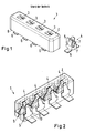
- the known from the prior art contact carrier 1 has a contact carrier housing 2, in which four contact openings 3 are provided. From a bottom of the contact carrier 1, not shown, the contact carrier openings 3 are each equipped with a dual spring contact 4, which is shown separately next to the contact carrier housing 2.
- This dual-spring contact 4 has two resilient legs 5, each having a connection portion 6 for forming a solder tab and contact springs 7 for receiving a mating connector, not shown. As an example, the connecting lugs 6 can be seen at a lower edge 8 of the contact carrier housing 2.
- the dual-spring contact 4 according to the prior art is integrally formed, wherein it is punched out for the production of a flat piece of sheet metal and a bend must be made in several directions in space.
- the in Fig. 2 illustrated erfindunumblee contact carrier 1 is provided with two-part dual-spring contacts, which are each formed by two resilient legs 5, which are fixed opposite in the contact carrier housing 2.
- To fix the springs in the legs 5 are each provided with a locking groove 9 and a latch 10 on each side.
- An inventive dual-spring contact 4 is in the in Fig. 3 shown second view of a contact carrier 1 according to the invention shown separately.
- the two resilient legs 5 of the dual-spring contact 4 are two separate components. This offers the advantage that a resistance between the connection tabs 6 can provide information as to whether a mating connector, not shown, is inserted or whether a contact resistance with an inserted mating connector changes and / or is outside predetermined tolerances.
- a contact dome 12 is embossed in the contact spring sections 11.
- a substantially point-shaped contact with a defined contact surface is made to a mating connector, not shown.
- a spring force between the opposite contact spring portions 11 can be adjusted by a corresponding bending of the resilient legs 5. Due to the two-part design of the dual-spring contact 4, this is possible in a particularly simple manner before assembly or before insertion into the contact carrier housing 2.
- a contact carrier 1 is simplified with a component 13 according to the invention, which is in Fig. 4 is shown.
- This has a strip-shaped carrier element 14 as well as four component elements 15 extending therefrom, each of which has a terminal strap section 16 and a contact spring section 11.
- These two sections 11, 16 are used to form the in Fig. 3 illustrated terminal lugs 6 and the contact spring portions 11 provided.
- a contact dome 12 is formed in the component 13 in the individual contact spring sections 11. This contact dome 12 is preferably formed at the same time in a punching of the component 13 from a band-shaped plate 17 shown in dashed lines.
- the component 13 with the component elements 15 is inserted from a rear side or underside of the contact carrier housing 2 into the housing such that the component elements 15 extend into the contact openings provided in the housing. Subsequently, the component 13 is angled to form the solder tabs and that substantially at an angle of 90 °. Subsequently, the carrier element 14 is separated along the dividing line 18 shown in broken lines from the component elements 15. In an alternative embodiment, the bending can also take place after the separation.
- two components 13 may be provided in the band-shaped plate 17, which are arranged to each other so that component elements of a second component, not shown, engage in the gaps 19 of the first component 13.
- the component 13 is in an embodiment not shown substantially longer than the provided with only four component elements 15 component 13 and is for example a band-shaped structure with a length of for example several meters, which can be wound onto a roll.
- circular spacer marks 20 are arranged in the carrier element 14, which provide precise control of advancement of the carrier element or precise positioning of the carrier element in a Abtrennvorgang to separate the desired number of component elements 15 allows.
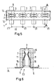
- These distance marks 20 are arranged as well as the component elements 15 at a defined distance, as shown in the Fig. 5 is explained more clearly.
- the contact carrier 1 shown in a plan view is provided with four contact openings 3, the center lines 21 each having a defined grid spacing 22 from each other. Accordingly, the contact springs 7 are aligned with their contact points 12 each centered with respect to the respective center line 21. This ensures that the terminal lugs 6 are also aligned exactly in the defined grid spacing 22 to each other.
- FIG. 6 A detail view along the section line AA in Fig. 5 is in the Fig. 6 shown.
- the two resilient legs 5 are inserted from a bottom 23 in the contact carrier housing 2, so that the contact spring portions 11 extend with the contact springs 7 from the bottom 23 into the contact opening 3.
- the connecting lugs 6 are formed by bending the resilient legs 5, wherein the connecting lugs 6 are precisely aligned to a connecting plane 24 shown in dashed lines. Such a precise alignment is achieved, in particular, when the component elements 15 are angled together prior to the separation of the carrier elements and thereby aligned with each other.
Abstract
Description
Die Erfindung betrifft einen Kontaktträger mit Federkontakten, die mindestens zwei federnde Schenkel aufweisen, sowie ein Bauteil und ein Verfahren zur Konfektionierung eines Kontaktträgers.The invention relates to a contact carrier with spring contacts having at least two resilient legs, and a component and a method for packaging a contact carrier.
Derartige Kontaktträger werden beispielsweise in Form von Anschlussleisten oder dgl. zur Bereitstellung elektrischer Kontakte in vielen Bereichen verwendet. Beispielsweise wird ein Kontaktträger in Form einer Federkontaktierungsleiste als Leiterplattenverbinder insbesondere zur Verarbeitung auf einer Leiterplatte in Reflow-Löttechnik verwendet. Bei einem Kontaktträger mit Dual-Federkontakten gemäß dem Stand der Technik, wie er in
Aufgabe der vorliegenden Erfindung ist es, einen Kontaktträger mit Dual-Federkontakten bereitzustellen, welcher hinsichtlich Aufbau, Herstellung und Konfektionierung vereinfacht wird, so dass dieser insbesondere einfacher und kostengünstiger herstellbar ist.Object of the present invention is to provide a contact carrier with dual-spring contacts, which is simplified in terms of design, manufacture and packaging, so that this particular easier and cheaper to produce.
Diese Aufgabe wird durch einen Kontaktträger mit den Merkmalen des Anspruches 1, ein Bauteil zur Konfektionierung eines Kontaktträgers mit den Merkmalen des Anspruches 6 sowie ein Verfahren zum Konfektionieren eines Kontaktträgers nach den Merkmalen des Anspruches 11 gelöst. Vorteilhafte Ausgestaltungen und Weiterbildungen sind in den jeweiligen abhängigen Ansprüchen angegeben.This object is achieved by a contact carrier with the features of
Bei einem erfindungsgemäßen Kontaktträger mit Federkontakten, die mindestens zwei federnde Schenkel aufweisen, sind die zwei federnden Schenkel als zweiteiliger Dual-Federkontakt ausgebildet und einander gegenüberliegend in einem Kontaktträgergehäuse fixiert.In a contact carrier according to the invention with spring contacts having at least two resilient legs, the two resilient legs are formed as a two-part dual-spring contact and fixed opposite each other in a contact carrier housing.
Vorteilhafterweise ermöglicht dies eine Vereinfachung eines Herstellungsprozesses. Dabei kann insbesondere eine Veredelung wie beispielsweise eine Galvanisierung, Beschichtung oder dgl. der Einzelkontakte vereinfacht werden. Weiter vorteilhaft wird ermöglicht, dass durch elektrische Messungen bei einer Kontaktierung der beiden Schenkel Informationen über einen Zustand des Steckkontaktes gewonnen werden können. Beispielsweise kann bei einem eingesteckten Gegenkontakt der Übergangswiderstand gegenüberliegender Schenkel gemessen werden. Vorteilhafterweise ermöglicht dies eine Überprüfung des Übergangswiderstandes über die Lebensdauer der Verbindung. Weiterhin kann mittels einer Durchgangsmessung an gegenüberliegenden Schenkeln überprüft werden, ob ein Gegenkontakt eingesteckt ist.Advantageously, this allows a simplification of a manufacturing process. In this case, in particular, a refinement such as, for example, a galvanization, coating or the like of the individual contacts can be simplified. Further advantageously, it is possible that information about a state of the plug contact can be obtained by electrical measurements in a contacting of the two legs. For example, in the case of an inserted mating contact, the contact resistance of opposing legs can be measured. Advantageously, this allows a review of the contact resistance over the life of the connection. Furthermore, it can be checked by means of a passage measurement on opposite legs, whether a mating contact is inserted.
Weiterhin kann ein Herstellungsprozess dadurch vereinfacht werden, dass ein Biegeprozess im Gegensatz zum Stand der Technik nur noch in einer einzigen Richtung erforderlich ist.Furthermore, a manufacturing process can be simplified in that a bending process is required in contrast to the prior art only in a single direction.
Bei dem Kontaktträger handelt es sich insbesondere um einen SMD-Kontaktträger, welcher mittels lötfähiger Anschlussflächen direkt auf eine Leiterplatte oder dgl. gelötet oder gesteckt werden kann. Es kann sich jedoch auch allgemein um eine Kontaktanordnung, Kontaktleiste, Anschlussleiste oder dgl. handeln. Die Dual-Federkontakte sind insbesondere so ausgestaltet, dass sie wenigstens einen Gegenstecker in Form beispielsweise einer Messerleiste aufnehmen können. Eine derartige Messerleiste ist beispielsweise als Leiterplattenverbinder oder als Leitungsanschluss vorgesehen. An Stelle von messerartigen Gegensteckern oder Messerleisten können auch andere gebräuchliche Gegensteckerformen, beispielsweise zylinderförmige Gegenstecker, vorgesehen sein. Ferner können auch einzelne in eine Leiterplatte eingepresste Kontakte als Gegenkontakte verwendet werden.The contact carrier is in particular an SMD contact carrier, which can be soldered or plugged directly onto a printed circuit board or the like by means of solderable connection surfaces. However, it can also generally be a contact arrangement, contact strip, terminal block or the like. Act. The dual-spring contacts are in particular designed so that they can accommodate at least one mating connector in the form of, for example, a male connector. Such a male connector is provided for example as a printed circuit board connector or as a line connection. In the place of knife-like Mating connectors or male connectors, other common mating connector shapes, such as cylindrical mating connector can be provided. Furthermore, individual contacts pressed into a printed circuit board can also be used as mating contacts.
Ein eingesteckter Gegenstecker kann zwischen zwei federnden Schenkeln insbesondere form- und/oder kraftschlüssig gehalten werden. Das Kontaktträgergehäuse dient vorzugsweise gleichzeitig einer Isolierung der verschiedenen federnden Schenkel voneinander. Insbesondere wird ein Kontaktträgergehäuse aus Kunststoff verwendet.An inserted mating connector can be held between two resilient legs in particular positive and / or non-positive. The contact carrier housing is preferably at the same time an isolation of the various resilient legs from each other. In particular, a contact carrier housing made of plastic is used.
Gemäß einer Weiterbildung des Kontaktträgers ist vorgesehen, dass jeder der federnden Schenkel identisch aufgebaut ist. Vorteilhafterweise können dadurch die Kontaktöffnungen zur Aufnahme der federnden Schenkel bzw. Dual-Federkontakte gleich ausgestaltet werden, was insbesondere einen Konstruktionsaufwand verringert. Weiterhin kann vorzugsweise eine Anzahl zur Herstellung verwendeter Werkzeuge, insbesondere Stanzwerkzeuge, verringert werden. Ein verbesserter elektrischer Kontakt zwischen einem federnden Schenkel und einem Gegenstecker wird vorzugsweise erreicht, wenn die Kontaktfläche auf einem federnden Schenkel als Kontaktkalotte ausgebildet ist. Die Kontaktkalotte bildet insbesondere einen definierten Kontaktpunkt auf einer flachen Gegenkontaktfläche und ermöglicht eine sichere Kontaktierung zum Gegenkontakt.According to a development of the contact carrier is provided that each of the resilient legs is constructed identically. Advantageously, characterized the contact openings for receiving the resilient leg or dual spring contacts can be configured the same, which in particular reduces a design effort. Furthermore, preferably a number of tools used for the production, in particular punching tools, can be reduced. An improved electrical contact between a resilient leg and a mating connector is preferably achieved when the contact surface is formed on a resilient leg as a contact dome. In particular, the contact dome forms a defined contact point on a flat mating contact surface and enables secure contacting with the mating contact.
Eine Konfektionierung des Kontaktträgers kann verbessert werden, wenn mehrere zweiteilige Dual-Federkontakte in einem Raster angeordnet sind. Vorzugsweise ermöglicht dies auch eine einfachere automatisierte Bestückung des Kontaktträgers mit Gegensteckern. Des Weiteren kann eine insbesondere automatisierte Bestückung des Kontaktträgers mit den federnden Schenkeln vereinfacht werden. Das Raster ist insbesondere ein- oder zweidimensional vorgesehen. Insbesondere wird ein rechtwinkliges Raster verwendet. Es können jedoch auch andere Rasterformen verwendet werden, in denen benachbarte Dual-Federkontakte einen definierten Abstand aufweisen.An assembly of the contact carrier can be improved if several two-part dual-spring contacts are arranged in a grid. Preferably, this also allows a simpler automated assembly of the contact carrier with mating connectors. Furthermore, a particularly automated assembly of the contact carrier with the resilient legs can be simplified. The grid is provided in particular one or two-dimensional. In particular, a rectangular grid is used. It can, however, too Other raster forms are used, in which adjacent dual-spring contacts have a defined distance.
Für eine Fixierung der federnden Schenkel in dem Kontaktträgergehäuse können verschiedene Varianten vorgesehen sein. Beispielsweise können die federnden Schenkel eingeschraubt, eingeklebt, eingeklemmt, eingegossen, form-oder kraftschlüssig fixiert sein.For a fixation of the resilient legs in the contact carrier housing different variants can be provided. For example, the resilient legs can be screwed in, glued, clamped, cast in, positively or non-positively fixed.
Für eine einfache Konfektionierung ist gemäß einer Weiterbildung des Kontaktes vorgesehen, dass die federnden Schenkel jeweils mittels wenigstens einer Rastnase und/oder wenigstens einer Rastnut in dem Kontaktträger befestigt sind. Beispielsweise weist der federnde Schenkel wenigstens eine Rastnase auf, welche bei einem Einstecken des federnden Schenkels in das Kontaktträgergehäuse in einer darin vorgesehenen Rastnut einrastet. Es versteht sich von selbst, dass auch umgekehrt an dem federnden Schenkel wenigstens eine Rastnut und in dem Kontaktträgergehäuse wenigstens eine Rastnase vorgesehen sein können. Ein derartiges Verrastemittel ist insbesondere zwischen einem Anschlusslaschenabschnitt zur Bildung einer Anschlusslasche und einem Kontaktfederabschnitt zur Bildung einer Kontaktfeder des federnden Schenkels vorgesehen. Die federnden Schenkel sind insbesondere wiederholbar lösbar in das Kontaktträgergehäuse einsteckbar.For a simple assembly is provided according to a development of the contact that the resilient legs are each secured by at least one locking lug and / or at least one locking groove in the contact carrier. For example, the resilient leg on at least one locking lug, which engages in a plug-in housing of the resilient leg in the contact carrier housing in a locking groove provided therein. It goes without saying that at least one locking groove and in the contact carrier housing at least one locking lug can also be provided on the resilient leg. Such a latching means is provided in particular between a connecting lug portion for forming a connecting lug and a contact spring portion for forming a contact spring of the resilient leg. The resilient legs are in particular reproducibly releasably inserted into the contact carrier housing.
Die Erfindung betriff außerdem ein Bauteil zur Konfektionierung eines Kontaktträgers, wobei das Bauteil wenigstens ein Trägerelement aufweist, von dem sich wenigstens zwei Bauteilelemente, welche jeweils wenigstens einen Anschlusslaschenabschnitt und jeweils wenigstens einen Kontaktfederabschnitt aufweisen, zur Bildung von Anschlusslaschen und Kontaktfedern wenigstens zweier Kontakte, insbesondere zweier Dual-Kontakte, erstrecken.The invention also relates to a component for assembling a contact carrier, wherein the component has at least one carrier element, of which at least two component elements, each having at least one terminal tab portion and at least one contact spring portion to form terminal tabs and contact springs of at least two contacts, in particular two Dual contacts, extend.
Vorteilhafterweise kann dadurch ein Kontaktträger gleichzeitig mit mehreren Federkontakten, insbesondere Dual-Federkontakten, bestückt werden. Dies ermöglicht insbesondere eine vergrößerte Bestückungsgeschwindigkeit und eine verbesserte Positioniergenauigkeit.Advantageously, a contact carrier can thereby be equipped simultaneously with a plurality of spring contacts, in particular dual spring contacts. This allows in particular an increased insertion speed and improved positioning accuracy.
Das Trägerelement ist insbesondere als Trägerstreifen, beispielsweise bandförmig, ausgestaltet. Es versteht sich von selbst, dass mehr als zwei Bauteilelemente von dem Bauteil erstreckt sein können. Beispielsweise sind drei, vier oder eine vielfache Anzahl von zwei Bauteilelementen vorgesehen. Insbesondere sind benachbarte Bauteilelemente zur Bildung von Anschlusslaschen und Kontaktfedern zwei benachbarter Kontakte, insbesondere Dual-Federkontakte, vorgesehen. Die Bauteilelemente können jedoch auch so an dem Trägerelement angeordnet sein, dass nur ein Teil der in einem Kontaktträgergehäuse vorgesehenen Kontaktöffnungen selektiv bestückt wird. Dies wird beispielsweise verwendet, wenn Kontakte mit unterschiedlichen Eigenschaften vorgesehen werden sollen.The carrier element is designed in particular as a carrier strip, for example in the form of a ribbon. It goes without saying that more than two component elements can be extended from the component. For example, three, four or a multiple number of two component elements are provided. In particular, adjacent component elements for forming connecting tabs and contact springs of two adjacent contacts, in particular dual-spring contacts, are provided. However, the component elements can also be arranged on the carrier element such that only a part of the contact openings provided in a contact carrier housing is selectively populated. This is used, for example, when providing contacts with different properties.
Hinsichtlich einer Konfektionierung ist es günstig, wenn die Bauteilelemente parallel zueinander angeordnet sind. Insbesondere sind die Bauteilelemente zinkenförmig zueinander angeordnet, so dass Trägerelemente und Bauteilelemente eine in etwa kammartige Struktur bilden.With regard to a packaging, it is advantageous if the component elements are arranged parallel to each other. In particular, the component elements are arranged in the shape of tines with respect to one another, so that carrier elements and component elements form an approximately comb-like structure.
In einer Ausgestaltung des Bauteils sind die Bauteilelemente in einem Raster angeordnet. Das Raster entspricht dabei insbesondere dem vorstehend beschriebenen Raster der Dual-Federkontakte. Diese Anordnung ermöglicht insbesondere eine einfachere und/oder schnellere Herstellung.In one embodiment of the component, the component elements are arranged in a grid. The grid corresponds in particular to the grid of the dual spring contacts described above. This arrangement in particular allows easier and / or faster production.
Zur Verrastung bei einem Einstecken in einen Kontaktträger bzw. ein Kontaktträgergehäuse weisen die Bauteilelemente gemäß einer Weiterbildung wenigstens eine Rastnase und/oder eine Rastnut, insbesondere zwischen Kontaktfederabschnitt und Anschlussabschnitt, auf. Diese Verrastemittel können beispielsweise in etwa mittig an den Bauteilelementen vorgesehen sein.For latching when plugged into a contact carrier or a contact carrier housing, the component elements according to a development, at least one locking lug and / or a locking groove, in particular between contact spring portion and connection section, on. These latching means can be provided, for example, approximately in the middle of the component elements.
Hinsichtlich einer Herstellung ist es günstig, wenn das Bauteil ein ebenes, insbesondere bandförmiges, Blechteil ist. Dies ermöglicht insbesondere eine preisgünstige Herstellung aus einem Bandmaterial mittels beispielsweise eines Stanzprozesses. Weiterhin ermöglicht die Verwendung eines Bleches vorzugsweise ein Aufrollen des Bauteils. Beispielsweise kann der Trägerstreifen mit den davon erstreckten Bauteilelementen leicht auf eine Rolle aufgewickelt werden.With regard to a production, it is advantageous if the component is a flat, in particular band-shaped, sheet metal part. This allows in particular an inexpensive production of a strip material by means of, for example, a stamping process. Furthermore, the use of a sheet preferably allows the component to be rolled up. For example, the carrier strip with the component elements extending therefrom can be easily wound onto a roll.
Die Erfindung betrifft des Weiteren ein Verfahren zum Konfektionieren eines Kontaktträgers, insbesondere gemäß einer der vorstehend beschriebenen Ausgestaltungen, wobei ein Bauteil, insbesondere gemäß einer der vorstehend beschriebenen Ausgestaltungen, mit einem Trägerelement und wenigstens zwei sich von dem Trägerelement erstreckenden Bauteilelementen mit den Bauteilelementen in einen Kontaktträger mit wenigstens zwei Kontaktöffnungen eingesetzt wird. Durch die Bauteilelemente werden federnde Schenkel gebildet, und das Trägerelement wird abgetrennt, wobei die Bauteilelemente voneinander getrennt werden. Die Bauteilelemente werden dabei insbesondere in verschiedene Kontaktöffnungen eingesteckt. Insbesondere werden benachbarte Bauteilelemente in benachbarte Kontaktöffnungen eingesetzt.The invention further relates to a method for assembling a contact carrier, in particular according to one of the embodiments described above, wherein a component, in particular according to one of the embodiments described above, with a carrier element and at least two extending from the carrier element component elements with the component elements in a contact carrier is used with at least two contact openings. By the component elements resilient legs are formed, and the carrier element is separated, wherein the component elements are separated from each other. The component elements are thereby inserted in particular into different contact openings. In particular, adjacent component elements are inserted into adjacent contact openings.
Je nach gewünschter Anzahl von Kontakten bzw. vorhandener Anzahl von Kontaktöffnungen wird das Bauteil vor dem Einsetzen zur Auswahl der Anzahl der Bauteilelemente gemäß einer Variante des Verfahrens abgelenkt. Die Bauteilelemente können beispielsweise zur Bildung von Lötlaschen vor oder nach dem Abtrennen des Trägerelementes abgewinkelt werden.Depending on the desired number of contacts or existing number of contact openings, the component is deflected before insertion for selecting the number of component elements according to a variant of the method. The component elements can be angled, for example, to form solder tabs before or after the separation of the carrier element.
Ein Herstellungsprozess kann vereinfacht werden, wenn die Bauteilelemente in eine gemeinsame Richtung abgewinkelt werden. Insbesondere ermöglicht dies, einen Biegeprozess besser in einem vorangehenden Stanzprozess zu integrieren, so dass die Produktionsgeschwindigkeit erhöht werden kann.A manufacturing process can be simplified if the component elements are angled in a common direction. In particular, this allows to integrate a bending process better in a previous punching process, so that the production speed can be increased.
Für eine präzise Anordnung der Kontakte in dem Kontaktträger bzw. dem Kontaktträgergehäuse können die Bauteilelemente zweier in den Kontaktträger gegenüberliegend eingesetzte Bauteile vor dem Abtrennen der Trägerelemente gemeinsam abgewinkelt werden, wobei beide Bauteile und/oder die Bauteilelemente zueinander ausgerichtet werden. Dies ermöglicht vorzugsweise eine gute Einhaltung einer im Hinblick auf eine Verwendung als SMD-Bauteil wünschenswerten Planarität von Anschlusslaschen bzw. Lötlaschen.For a precise arrangement of the contacts in the contact carrier or the contact carrier housing, the component elements of two opposing components used in the contact carrier before the separation of the carrier elements are angled together, both components and / or the component elements are aligned. This preferably makes it possible to maintain a good planarity of connecting straps or solder straps which is desirable with regard to use as an SMD component.
Zur Bereitstellung der Bauteile werden diese beispielsweise aus einem Blech ausgestanzt.To provide the components they are punched out of a sheet, for example.
Eine Herstellung lässt sich dabei vorzugsweise beschleunigen, wenn wenigstens zwei Bauteile aus einem Blech ausgestanzt werden, wobei die Bauteile so angeordnet sind, dass wenigstens ein Bauteilelement des einen Bauteils in eine Lücke zwischen Bauteilelementen des anderen Bauteils eingreift. Durch eine derartige in etwa kammartig ineinandergreifende Anordnung wenigstens zweier Bauteile kann die Anzahl der mit einem einzigen Stanzvorgang hergestellten Bauteile zumindest verdoppelt und die Materialausnutzung verbessert werden.A production can be accelerated preferably when at least two components are punched out of a metal sheet, wherein the components are arranged so that at least one component element of the one component engages in a gap between component elements of the other component. By such an approximately comb-like interlocking arrangement of at least two components, the number of components produced with a single punching operation can be at least doubled and the material utilization can be improved.
Weitere Merkmale, Vorteile und Anwendungsmöglichkeiten der vorliegenden Erfindung ergaben sich auch aus der nachfolgenden Beschreibung von Ausführungsbeispielen und der Zeichnung. Dabei bilden alle beschriebenen und/oder bildlich dargestellten Merkmale für sich oder in beliebiger Kombination den Gegenstand der vorliegenden Erfindung, auch unabhängig von ihrer Zusammenfassung in den Ansprüchen oder deren Rückbeziehung.Other features, advantages and applications of the present invention were also apparent from the following description of exemplary embodiments and the drawings. All described and / or illustrated features alone or in any combination form the subject matter of the present invention, also independent of their summary in the claims or their dependency.
- Fig. 1Fig. 1
- einen Kontaktträger gemäß dem Stand der Technik;a contact carrier according to the prior art;
- Fig. 2Fig. 2
- eine erste dreidimensionale Ansicht eines erfindungsgemäßen Kontaktträgers;a first three-dimensional view of a contact carrier according to the invention;
- Fig. 3Fig. 3
- eine zweite dreidimensionale Ansicht eines erfindungsgemäßen Kontaktträgers;a second three-dimensional view of a contact carrier according to the invention;
- Fig. 4Fig. 4
-
ein erfindungsgemäßes Bauteil zur Konfektionierung eines Kontaktträgers gemäß
Fig. 2 oder3 ,an inventive component for packaging a contact carrier according toFig. 2 or3 . - Fig. 5Fig. 5
- eine Aufsicht auf einen erfindungsgemäßen Kontaktträger unda plan view of a contact carrier according to the invention and
- Fig. 6Fig. 6
- einen Querschnitt eines erfindungsgemäßen Kontaktträgers.a cross section of a contact carrier according to the invention.
Der aus dem Stand der Technik bekannte Kontaktträger 1 weist ein Kontaktträgergehäuse 2 auf, in welchem vier Kontaktöffnungen 3 vorgesehen sind. Von einer nicht dargestellten Unterseite des Kontaktträgers 1 sind die Kontaktträger-öffnungen 3 jeweils mit einem Dual-Federkontakt 4 bestückt, welcher separat neben dem Kontaktträgergehäuse 2 dargestellt ist. Dieser Dual-Federkontakt 4 weist zwei federnde Schenkel 5 mit jeweils einem Anschlussabschnitt 6 zur Bildung einer Lötlasche und Kontaktfedern 7 zur Aufnahme eines nicht dargestellten Gegensteckers auf. Ansatzweise sind die Anschlusslaschen 6 an einem unteren Rand 8 des Kontaktträgergehäuses 2 zu sehen. Der Dual-Federkontakt 4 gemäß dem Stand der Technik ist einstückig ausgebildet, wobei er zur Herstellung aus einem ebenen Stück Blech ausgestanzt wird und eine Verbiegung in mehreren Raumrichtungen erfolgen muss.The known from the prior
Demgegenüber ist der in
Ein erfindungsgemäßer Dual-Federkontakt 4 ist in der in
In den Kontaktfederabschnitten 11 ist jeweils eine Kontaktkalotte 12 eingeprägt. Dadurch wird ein im wesentlicher punktförmiger Kontakt mit einer definierten Kontaktfläche zu einem nicht dargestellten Gegenstecker hergestellt. Eine Federkraft zwischen den gegenüberliegenden Kontaktfederabschnitten 11 kann durch eine entsprechende Verbiegung der federnden Schenkel 5 eingestellt werden. Auf Grund der zweiteiligen Ausgestaltung des Dual-Federkontaktes 4 ist dies in besonders einfacher Weise vor einer Konfektionierung bzw. vor einem Einsetzen in das Kontaktträgergehäuse 2 möglich.In each case a
Die Herstellung eines erfindungsgemäßen Kontaktträgers 1 wird mit einem erfindungsgemäßen Bauteil 13 vereinfacht, welches in
Zur Konfektionierung eines Kontaktträgers wird das Bauteil 13 mit den Bauteilelementen 15 von einer Rückseite bzw. Unterseite des Kontaktträgergehäuses 2 so in das Gehäuse eingesetzt, dass sich die Bauteilelemente 15 in die im Gehäuse vorgesehenen Kontaktöffnungen erstrecken. Anschließend wird das Bauteil 13 zur Bildung der Lötlaschen abgewinkelt und zwar im Wesentlichen mit einem Winkel von 90°. Anschließend wird das Trägerelement 14 entlang der gestrichelt dargestellten Trennlinie 18 von den Bauteilelementen 15 abgetrennt. In einer alternativen Ausgestaltung kann das Abwinkeln auch nach dem Abtrennen erfolgen.For assembling a contact carrier, the
In einer nicht dargestellten Ausgestaltung können in dem bandförmigen Blech 17 auch zwei Bauteile 13 vorgesehen sein, welche so zueinander angeordnet sind, dass Bauteilelemente eines zweiten, nicht dargestellten Bauteiles in die Lücken 19 des ersten Bauteils 13 eingreifen.In one embodiment, not shown, two
Das Bauteil 13 ist in einer nicht dargestellten Ausgestaltung wesentlich länger als das mit lediglich vier Bauteilelementen 15 versehene Bauteil 13 und ist beispielsweise ein bandförmiges Gebilde mit einer Länge von beispielsweise mehreren Metern, welches auf eine Rolle aufgewickelt werden kann. Zur besseren Abzählung der von einer Konfektionierung eines Kontaktträgers erforderlichen Bauteilelemente 13 sind in dem Trägerelement 14 kreisförmige Distanzmarken 20 angeordnet, welche eine genaue Kontrolle eines Vorschubes des Trägerelementes bzw. eine genaue Positionierung des Trägerelementes bei einem Abtrennvorgang zur Separierung der gewünschten Anzahl der Bauteilelemente 15 ermöglicht. Diese Distanzmarken 20 sind ebenso wie die Bauteilelemente 15 in einem definierten Abstand angeordnet, wie dies in der
Der in einer Aufsicht dargestellte Kontaktträger 1 ist mit vier Kontaktöffnungen 3 versehen, deren Mittellinien 21 jeweils einen definierten Rasterabstand 22 voneinander aufweisen. Dementsprechend sind die eingesetzten Kontaktfedern 7 mit ihren Kontaktkalotten 12 jeweils zentriert bezogen auf die jeweilige Mittellinie 21 ausgerichtet. Dadurch wird gewährleistet, dass die Anschlusslaschen 6 ebenfalls genau in dem definierten Rasterabstand 22 zueinander ausgerichtet sind.The
Eine Detailansicht entlang der Schnittlinie A-A in
- 11
- Kontaktträgercontact support
- 22
- KontaktträgergehäuseContact support housing
- 33
- Kontaktöffnungcontact opening
- 44
- Dual-FederkontaktDual-spring contact
- 55
- federnder Schenkelresilient leg
- 66
- Anschlusslascheconnection tab
- 77
- Kontaktfedercontact spring
- 88th
- unterer Randlower edge
- 99
- Rastnutlocking groove
- 1010
- Rastnaselocking lug
- 1111
- KontaktfederabschnittTongue portion
- 1212
- Kontaktkalottecontact cup
- 1313
- Bauteilcomponent
- 1414
- Trägerelementsupport element
- 1515
- Bauteilelementpart feature
- 1616
- AnschlusslaschenabschnittConnection tab portion
- 1717
- bandförmiges Blechband-shaped sheet metal
- 1818
- Trennlinieparting line
- 1919
- Lückegap
- 2020
- Distanzmarkedistance mark
- 2121
- Mittelliniecenter line
- 2222
- Rasterabstandpitch
- 2323
- Unterseite (des Kontaktträgergehäuses)Bottom (of the contact carrier housing)
- 2424
- Anschlussebeneconnection level
Claims (15)
Applications Claiming Priority (1)
| Application Number | Priority Date | Filing Date | Title |
|---|---|---|---|
| DE102006057368 | 2006-12-04 |
Publications (2)
| Publication Number | Publication Date |
|---|---|
| EP1930987A2 true EP1930987A2 (en) | 2008-06-11 |
| EP1930987A3 EP1930987A3 (en) | 2009-05-06 |
Family
ID=39126187
Family Applications (1)
| Application Number | Title | Priority Date | Filing Date |
|---|---|---|---|
| EP07023394A Withdrawn EP1930987A3 (en) | 2006-12-04 | 2007-12-04 | Contact holder with resilient contact |
Country Status (1)
| Country | Link |
|---|---|
| EP (1) | EP1930987A3 (en) |
Cited By (7)
| Publication number | Priority date | Publication date | Assignee | Title |
|---|---|---|---|---|
| EP2164137A1 (en) * | 2008-09-11 | 2010-03-17 | Sumitomo Wiring Systems, Ltd. | A joint connector, joint terminal, a wiring harness with a joint connector and method of assembling it |
| CN101997203A (en) * | 2010-11-24 | 2011-03-30 | 中航光电科技股份有限公司 | Power contact element for rectangular electric connector |
| WO2012058807A1 (en) | 2010-11-03 | 2012-05-10 | Harting Electronics Gmbh & Co. Kg | Contact element for plug-in connector socket |
| EP2950397A1 (en) * | 2013-05-24 | 2015-12-02 | Iriso Electronics Co., Ltd. | Connector |
| DE102015225159A1 (en) * | 2015-12-14 | 2017-06-14 | Continental Automotive Gmbh | Magnetic field sensor with a plug socket |
| LU500674B1 (en) | 2021-09-21 | 2023-03-21 | Phoenix Contact Gmbh & Co | Electrical contact element |
| DE102021124327A1 (en) | 2021-09-21 | 2023-03-23 | Phoenix Contact Gmbh & Co. Kg | Electrical contact element |
Citations (6)
| Publication number | Priority date | Publication date | Assignee | Title |
|---|---|---|---|---|
| US4286837A (en) * | 1978-12-25 | 1981-09-01 | K.K. Elco International | Electrical connector, an insulator therefor and a fitting jig for an assembly of these |
| EP0820123A2 (en) * | 1996-07-16 | 1998-01-21 | Molex Incorporated | Edge connector for a printed circuit board |
| US6048221A (en) * | 1998-08-13 | 2000-04-11 | The Whitaker Corporation | Electrical connector with reduced contact footprint |
| US20010000368A1 (en) * | 1998-04-02 | 2001-04-26 | Ward Terrence S. | Method of manufacturing electrical connector contacts |
| US6261107B1 (en) * | 1998-01-16 | 2001-07-17 | Molex Incorporated | Surface mount connector having improved terminal structure |
| EP1703600A1 (en) * | 2005-03-17 | 2006-09-20 | Sumitomo Wiring Systems, Ltd. | Chained terminals and method of forming chained terminals |
-
2007
- 2007-12-04 EP EP07023394A patent/EP1930987A3/en not_active Withdrawn
Patent Citations (6)
| Publication number | Priority date | Publication date | Assignee | Title |
|---|---|---|---|---|
| US4286837A (en) * | 1978-12-25 | 1981-09-01 | K.K. Elco International | Electrical connector, an insulator therefor and a fitting jig for an assembly of these |
| EP0820123A2 (en) * | 1996-07-16 | 1998-01-21 | Molex Incorporated | Edge connector for a printed circuit board |
| US6261107B1 (en) * | 1998-01-16 | 2001-07-17 | Molex Incorporated | Surface mount connector having improved terminal structure |
| US20010000368A1 (en) * | 1998-04-02 | 2001-04-26 | Ward Terrence S. | Method of manufacturing electrical connector contacts |
| US6048221A (en) * | 1998-08-13 | 2000-04-11 | The Whitaker Corporation | Electrical connector with reduced contact footprint |
| EP1703600A1 (en) * | 2005-03-17 | 2006-09-20 | Sumitomo Wiring Systems, Ltd. | Chained terminals and method of forming chained terminals |
Cited By (14)
| Publication number | Priority date | Publication date | Assignee | Title |
|---|---|---|---|---|
| EP2164137A1 (en) * | 2008-09-11 | 2010-03-17 | Sumitomo Wiring Systems, Ltd. | A joint connector, joint terminal, a wiring harness with a joint connector and method of assembling it |
| US7883362B2 (en) | 2008-09-11 | 2011-02-08 | Sumitomo Wiring Systems, Ltd. | Joint connector, joint terminal and a wiring harness with a joint connector |
| WO2012058807A1 (en) | 2010-11-03 | 2012-05-10 | Harting Electronics Gmbh & Co. Kg | Contact element for plug-in connector socket |
| US8926352B2 (en) | 2010-11-03 | 2015-01-06 | HARTING Electronics GmbH | Contact element for plug-in connector socket |
| CN101997203A (en) * | 2010-11-24 | 2011-03-30 | 中航光电科技股份有限公司 | Power contact element for rectangular electric connector |
| CN101997203B (en) * | 2010-11-24 | 2013-03-27 | 中航光电科技股份有限公司 | Power contact element for rectangular electric connector |
| EP2950397A1 (en) * | 2013-05-24 | 2015-12-02 | Iriso Electronics Co., Ltd. | Connector |
| CN105322332A (en) * | 2013-05-24 | 2016-02-10 | 意力速电子工业株式会社 | Connector |
| US9466907B2 (en) | 2013-05-24 | 2016-10-11 | Iriso Electronics Co., Ltd. | Connector |
| CN113488790A (en) * | 2013-05-24 | 2021-10-08 | 意力速电子工业株式会社 | Connector with a locking member |
| DE102015225159A1 (en) * | 2015-12-14 | 2017-06-14 | Continental Automotive Gmbh | Magnetic field sensor with a plug socket |
| LU500674B1 (en) | 2021-09-21 | 2023-03-21 | Phoenix Contact Gmbh & Co | Electrical contact element |
| DE102021124327A1 (en) | 2021-09-21 | 2023-03-23 | Phoenix Contact Gmbh & Co. Kg | Electrical contact element |
| WO2023046550A1 (en) | 2021-09-21 | 2023-03-30 | Phoenix Contact Gmbh & Co. Kg | Electric contact element |
Also Published As
| Publication number | Publication date |
|---|---|
| EP1930987A3 (en) | 2009-05-06 |
Similar Documents
| Publication | Publication Date | Title |
|---|---|---|
| DE69722392T2 (en) | ELECTRICAL CONNECTOR COMPOSED OF DISK-SINGLE ITEMS | |
| DE69326613T2 (en) | CARD CONNECTOR WITH FLAT BACK | |
| DE102005021568A1 (en) | Printed circuit board with pressfit connection | |
| DE102016108825B4 (en) | Clamping arrangement and connection terminal | |
| EP1930987A2 (en) | Contact holder with resilient contact | |
| EP3018761B1 (en) | Circuit board connecting terminal | |
| DE102013107156B4 (en) | PCB connector | |
| LU92994B1 (en) | DIN rail assembly with a bus system and a circuit board having electronic device | |
| DE602004009268T2 (en) | Interconnects | |
| DE3345435A1 (en) | CONNECTORS, IN PARTICULAR CONNECTORS, AND METHOD FOR THE PRODUCTION THEREOF | |
| DE2405464A1 (en) | MULTIPLE CONNECTORS FOR MAKING SEVERAL ELECTRICAL CONNECTIONS | |
| EP0645856B1 (en) | Method of making contact elements-groups for a connecting device | |
| DE102011079136A1 (en) | Direct plug-in element with integrated lock | |
| LU101643B1 (en) | Plug contact element, direct plug connector, method for producing a plug contact element and method for producing a direct plug connector | |
| DE102007044857A1 (en) | connecting element | |
| DE102011089020B4 (en) | Contact connector and method for producing a contact connector | |
| WO2016050586A1 (en) | Male strip connector | |
| DE10260241A1 (en) | Kontaktierungsbauteil | |
| WO2015132062A1 (en) | Connection arrangement, method for producing a connection arrangement, and electric device comprising a connection arrangement | |
| WO2019092080A1 (en) | Solder socket contact and contact module for a printed circuit board | |
| DE102017207677A1 (en) | Board connector, board assembly, and method of making a board connector | |
| DE102012011047B4 (en) | Connection component and circuit arrangement with the connection component | |
| WO2018007087A1 (en) | Combination comprising a plug and a threading aid, threading aid, and assembly and method for attaching a plug to a printed circuit board | |
| DE102017220022B4 (en) | Buchsenlötkontakt and contact module for a printed circuit board | |
| DE102007034389B4 (en) | Multi-pin electrical connector |
Legal Events
| Date | Code | Title | Description |
|---|---|---|---|
| PUAI | Public reference made under article 153(3) epc to a published international application that has entered the european phase |
Free format text: ORIGINAL CODE: 0009012 |
|
| AK | Designated contracting states |
Kind code of ref document: A2 Designated state(s): AT BE BG CH CY CZ DE DK EE ES FI FR GB GR HU IE IS IT LI LT LU LV MC MT NL PL PT RO SE SI SK TR |
|
| AX | Request for extension of the european patent |
Extension state: AL BA HR MK RS |
|
| PUAL | Search report despatched |
Free format text: ORIGINAL CODE: 0009013 |
|
| AK | Designated contracting states |
Kind code of ref document: A3 Designated state(s): AT BE BG CH CY CZ DE DK EE ES FI FR GB GR HU IE IS IT LI LT LU LV MC MT NL PL PT RO SE SI SK TR |
|
| AX | Request for extension of the european patent |
Extension state: AL BA HR MK RS |
|
| RIC1 | Information provided on ipc code assigned before grant |
Ipc: H01R 43/16 20060101ALI20090330BHEP Ipc: H01R 13/11 20060101ALI20090330BHEP Ipc: H01R 12/22 20060101ALI20090330BHEP Ipc: H01R 12/36 20060101AFI20090330BHEP |
|
| 17P | Request for examination filed |
Effective date: 20091105 |
|
| AKX | Designation fees paid |
Designated state(s): AT BE BG CH CY CZ DE DK EE ES FI FR GB GR HU IE IS IT LI LT LU LV MC MT NL PL PT RO SE SI SK TR |
|
| 17Q | First examination report despatched |
Effective date: 20091221 |
|
| STAA | Information on the status of an ep patent application or granted ep patent |
Free format text: STATUS: THE APPLICATION IS DEEMED TO BE WITHDRAWN |
|
| 18D | Application deemed to be withdrawn |
Effective date: 20100706 |