EP1930930B1 - Transmission for a high-voltage circuit breaker - Google Patents
Transmission for a high-voltage circuit breaker Download PDFInfo
- Publication number
- EP1930930B1 EP1930930B1 EP06405508.0A EP06405508A EP1930930B1 EP 1930930 B1 EP1930930 B1 EP 1930930B1 EP 06405508 A EP06405508 A EP 06405508A EP 1930930 B1 EP1930930 B1 EP 1930930B1
- Authority
- EP
- European Patent Office
- Prior art keywords
- contact
- contact piece
- transmission
- movement
- pivoting
- Prior art date
- Legal status (The legal status is an assumption and is not a legal conclusion. Google has not performed a legal analysis and makes no representation as to the accuracy of the status listed.)
- Not-in-force
Links
Images

Classifications
-
- H—ELECTRICITY
- H01—ELECTRIC ELEMENTS
- H01H—ELECTRIC SWITCHES; RELAYS; SELECTORS; EMERGENCY PROTECTIVE DEVICES
- H01H33/00—High-tension or heavy-current switches with arc-extinguishing or arc-preventing means
- H01H33/70—Switches with separate means for directing, obtaining, or increasing flow of arc-extinguishing fluid
- H01H33/88—Switches with separate means for directing, obtaining, or increasing flow of arc-extinguishing fluid the flow of arc-extinguishing fluid being produced or increased by movement of pistons or other pressure-producing parts
- H01H33/90—Switches with separate means for directing, obtaining, or increasing flow of arc-extinguishing fluid the flow of arc-extinguishing fluid being produced or increased by movement of pistons or other pressure-producing parts this movement being effected by or in conjunction with the contact-operating mechanism
- H01H33/904—Switches with separate means for directing, obtaining, or increasing flow of arc-extinguishing fluid the flow of arc-extinguishing fluid being produced or increased by movement of pistons or other pressure-producing parts this movement being effected by or in conjunction with the contact-operating mechanism characterised by the transmission between operating mechanism and piston or movable contact
-
- H—ELECTRICITY
- H01—ELECTRIC ELEMENTS
- H01H—ELECTRIC SWITCHES; RELAYS; SELECTORS; EMERGENCY PROTECTIVE DEVICES
- H01H33/00—High-tension or heavy-current switches with arc-extinguishing or arc-preventing means
- H01H33/02—Details
- H01H2033/028—Details the cooperating contacts being both actuated simultaneously in opposite directions
-
- H—ELECTRICITY
- H01—ELECTRIC ELEMENTS
- H01H—ELECTRIC SWITCHES; RELAYS; SELECTORS; EMERGENCY PROTECTIVE DEVICES
- H01H33/00—High-tension or heavy-current switches with arc-extinguishing or arc-preventing means
- H01H33/02—Details
- H01H33/42—Driving mechanisms
Definitions
- the present invention relates to the field of dual power electrical circuit breakers.
- the invention further relates to a method for opening the contacts of an electrical circuit breaker.
- Circuit breakers usually have two contact pieces, each with a consumable contact (tulip and pin), which can be separated if necessary. To disconnect either only one contact piece or both contact pieces can be moved.
- a drive drives the tulip
- a gear or auxiliary transmission transmits the movement of the tulip on the pin are linear transmissions with a transmission ratio of typically 1: 1, such.
- the transmission ratio of the transmission is defined as the ratio of a speed of movement of the gear transmitted or generated (output motion, typically movement of the pin) to a speed of movement of a gear driving movement (drive motion, typically movement of the tulip).
- an auxiliary gear is shown with a stationary rotatably mounted gear
- the gear is driven by a rack.
- a lever for transmitting power to the mating contact is articulated at a fixed position.
- transmissions with a non-constant transmission ratio typically require a lot of space. Also, the time course of the transmission ratio of these transmissions is often satisfactory.
- Object of the present invention is to provide an improved dual drive for a circuit breaker.
- the object is achieved by the electric circuit breaker according to independent claim 1 and by the method for making contact opening of an electric circuit breaker according to independent claim 13.
- an electrical circuit breaker comprising: a first contact having a first contact, in particular a consumable contact cuff; a second contact piece with a second contact, in particular a consumable contact pin; a drive for moving the first contact piece longitudinally, ie parallel or anti-parallel to, a switching movement axis or switch axis, in particular relative to a housing of the circuit breaker; and a transmission for transmitting the movement of the first contact piece to a movement of the second contact piece.
- the transmission comprises: a first lever, a pivot member pivotable about a pivot axis, and a transmission mechanism for transmitting pivotal movement of the pivot member to movement of the second contact.
- the first lever is hinged to the first contact piece with a hinge and articulated to the pivot member by a thrust joint.
- the sliding joint defines a fixed angular relationship between the first lever and the pivot member such that rotational movement of the first lever pivots the pivot member whereas a thrust movement of the first pivot Levers does not pivot the pivot member.
- the hinges are preferably pure hinges, ie they do not allow relative thrust between the hinged parts.
- the thrust joint preferably defines a thrust axis which intersects the pivot axis.
- a method for contact opening of an electrical circuit breaker comprises a first contact piece with a first burnup contact, a second contact piece with a second burnup contact, a drive for moving the first contact piece along a switch axis and a transmission for moving the second contact piece, wherein the transmission has a first lever, which with a
- the method comprises the following steps: the first lever is moved by the movement of the first contact piece, the movement of the first lever preferably a rotational movement approximately about the pivot axis and thus superimposed a thrust movement is; the pivot member is pivoted by the movement, and preferably by the rotational movement, of the first lever about the pivot axis; and the pivoting movement of the pivoting member is transmitted by a transmission mechanism to a movement of the second contact piece, preferably to a longitudinal movement along the switching movement axis or switch axis.
- the first lever is articulated with a hinge to the first contact piece and hinged with a sliding joint to the pivot member.
- the invention also relates to a circuit breaker for carrying out the disclosed method.
- the invention is further directed to methods according to which the respective circuit breaker described work.
- Fig. 1 shows a first embodiment of a circuit breaker according to the invention.
- the circuit breaker comprises a first contactor 10 having a first consumable contact (not shown), which is typically configured as a tulip, and a second contactor 20 having a second consumable contact (not shown), which is typically configured as a pin.
- the Abbrandcarde and other elements of the circuit breaker, not shown, such as extinguishing devices for an arc by a protective gas, are designed in the usual way.
- sliding elements or tie rods or push rods 14, 24 are shown, which are connected in a suitable manner with the AbbrandWalleten or generally to be switched contacts of the switch.
- the contact pieces 10, 20 are typically longitudinal, ie parallel or antiparallel, movable to a switch axis or switching movement axis 3 by being mounted on rails or in plain bearings.
- the power switch further comprises an auxiliary gearbox or gearbox 2.
- the gearbox 2 has a first lever 30, a pivoting element 50, and a second lever 40.
- the first lever 30 is articulated with a rotary joint 31 to the first contact piece 10, and articulated with a sliding joint 35 or rotary sliding joint 35 to the pivot member 50.
- the pivoting element 50 is pivotably mounted about a pivot axis 56 with a pivot joint 55.
- the hinge 55 is advantageous to a stationary part of the circuit breaker, z. B. on its housing attached.
- the pivot axis 56 is stationary, for example, relative to the housing of the circuit breaker.
- the pivot axis 56 should be aligned perpendicular to the switch axis 3 in the rule.
- the pivot axis 56 is laterally offset from the switch axis 3 at a distance d.
- the pivot axis 56 in a laterally offset position between the switch axis 3 and the first contact piece 10, ie. As in Fig. 1 shown offset upwards, arranged.
- the articulation 35 defines a fixed angular relationship between the lever 30, i. between an axis defined by the lever 30 and its longitudinal extension, and the pivoting element 50.
- the pivoting element 50 is thus entrained by a rotational movement of the lever 30 at a constant relative angle and thus pivotable. A pushing movement of the lever 30 along a thrust axis of the sliding joint 35, however, does not pivot the pivoting element 50.
- the first lever 30 on a cylindrical or pestle-shaped end which is slidably mounted in the sliding joint 35 can also be the entire first lever 30 is cylindrical and in particular have a round cross-section.
- the first lever 30 could also be another, z. B. have rectangular cross-section.
- the sliding joint 35 then has a bore and in particular sliding surface or cylindrical guide of appropriate shape, so that a good positive contact for transmitting the rotational movement of the first lever 30 is effected on the pivot member 50.
- the sliding joint 35 is advantageously arranged so that the thrust axis is perpendicular to the pivot axis 56, and / or that the thrust axis intersects the pivot axis 56; however, this is not mandatory.
- the thrust axis is perpendicular to the pivot axis 56.
- the second lever 40 is pivotally connected to the swivel element 50 by means of a swivel joint 45 eccentrically to the swivel axis 56 and is rotatably connected to the second contact piece 20 by means of a further swivel joint 42.
- the second lever 40 thereby forms a transmission mechanism 40 for transmitting a pivotal movement of the pivot member 50 about the pivot axis 56 to a longitudinal movement of the second contact piece 20th
- Fig. 1 shows the circuit breaker in a closed state in which the Abbrandcarde the two contact pieces 10, 20 are in electrical contact with each other.
- the first contact piece 10 can be moved by a drive (not shown) along the switch axis 3 to the left.
- the transmission 2 can transmit this movement of the first contact piece 10 to an opposite movement with non-linear transfer characteristic for the second contact piece 20 to the right.
- the lever 30 is first pushed by the movement of the first contact piece 10 to the left into the sliding joint 35, so that the distance between the pivot 31 and the sliding joint 35 is shortened. Simultaneously, the lever 30 is rotated counterclockwise.
- the pivot member 50 Since the thrust joint 35 defines a fixed angular relationship between the lever 30 and the pivot member 50, the pivot member 50 is also pivoted about the pivot axis 56 in the counterclockwise direction. The pivoting movement of the pivoting element 50 is then transmitted by the lever 40 to a longitudinal movement of the second contact piece 20 along the switch axis 3 to the right. The movement of the second contact piece 20 is thus opposite to the movement of the first contact piece 10, ie directed to the right, so that the relative speed between the contact pieces 10 and 20 is increased by the additional movement, which is transmitted by the transmission 2 to the second contact piece 20.
- the lever 30 performs both a sliding and a rotating movement relative to the pivot axis 56.
- the lever 30 is pushed into the sliding joint 35, and rotated only by a relatively small amount.
- the rotational movement of the lever 30 gradually increases in proportion to the longitudinal movement of the first contact 10, whereas the sliding movement of the lever 30 decreases until the pivot 31 is vertically above the pivot 55.
- only a rotating movement and no sliding movement of the lever 30 takes place. If the first contact piece 10 is moved even further to the left, the lever 30 is pulled out of the sliding joint 35 again, and the rotating movement of the lever 30 gradually decreases again.
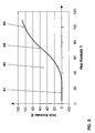
- Fig. 3 shows a hub-stroke diagram, wherein stroke equal to the distance covered movement distance of the contact pieces 10, 20 and the associated contacts referred.
- the diagram shows the lift curve 60, ie the stroke of the second contact piece 20 in mm (contact 2, vertical axis) as a function of the stroke of the first contact piece 10 in mm (contact 1, horizontal axis).
- the transmission ratio of the transmission 2 is given by the derivation of the lift curve 60.
- the stroke curve 60 shows that the transmission ratio is variable or not constant during a switching operation of the power switch, ie varies depending on the position of the contact pieces 10, 20 or the rotational position of the pivoting element 50.
- a first phase 61 the stroke of the second contact piece 20 hardly changes, ie the transmission ratio of the transmission 2 is approximately zero or small.
- This phase 61 corresponds to the in Fig. 1 illustrated state in which the lever 30 is pushed mainly into the sliding joint 35 and rotated only by a relatively small amount.
- the transmission ratio of the transmission 2 ie the slope of the lifting cam 60, large and in particular passes through a maximum when the pivot 31 is positioned vertically above the sliding joint 55.
- This phase 62 corresponds to the state in which almost exclusively a rotating movement and hardly a sliding movement of the lever 30 takes place.
- a subsequent third phase 63 the transmission ratio of the transmission 2 decreases again.
- the gearbox 2 has a much larger size Gear ratio as at the beginning of the movement, ie when fully closed circuit breaker.
- the transmission ratio of the transmission 2 in separating the contact may be greater by a factor greater than 2: 1 or even greater than 5: 1.
- a maximum transmission ratio is reached only when the contacts are disconnected. It is generally advantageous that the maximum transmission ratio is greater than 1: 1, preferably greater than 1.5: 1, and more preferably greater than 2: 1.
- the period between the physical separation or contact separation of the consumable contacts and the release of an insulating nozzle to extinguish the arc is selected to include the second phase 62, or at least part of the high gear ratio lift curve. It is therefore advantageous that the transmission ratio of the transmission 2 in the second phase 62 and / or between the contact separation of the AbbrandWallete and the release of the insulating nozzle for extinguishing the arc constantly above the value 1: 1, preferably above the value 1.5: 1, and more preferably above the value 2: 1 is selected. As a result, a high relative speed between the contact pieces 10 and 20 can be achieved in this entire period.
- the transmission ratio of the transmission 2 is limited in other than the above periods, yet the entire stroke of the contact pieces 10 and 20 can be kept low. Therefore, the quick pen movement, in particular, a gear ratio greater than 2: 1 or 1.5: 1 or 1: 1, can be limited to the period between contact separation and nozzle enable moment, and the power switch can be made compact at the same time. Due to the initially low transmission ratio can also be the period in which the first contact piece 10 must be accelerated by the drive, be separated from the period in which the second contact piece 20 is accelerated via the transmission 2 by the drive. Thus, the drive load can be distributed over a longer period, and load peaks for the drive can be reduced. As a result, the drive can be made weaker or a higher acceleration of the contacts or burned contact can be achieved.
- Fig. 2 shows a second inventive circuit breaker. In it are opposite Fig. 1 the same or similar parts with the same reference numerals. Unlike the transmission of Fig. 1 has the transmission 2 of Fig. 2 no second lever 40. Instead, the transmission mechanism for transmitting a pivotal movement of the pivot member 50 is formed on a movement of the second contact piece 20 by a gear 47 and a rack 48.
- the gear 47 is fixed to the pivot member 50 so that it is pivotally mounted or rotatable together with the pivot member 50 about the pivot axis 56. It has an axis of rotation which lies on the pivot axis 56.
- the rack 48 is mitbewegbar with the second contact piece 20 and attached thereto. The gear 47 is engaged with the rack 48 and drives it when needed.
- Fig. 2 illustrates that the transmission of the inventive circuit breaker with any known transmission mechanism 40; 47, 48 may be provided for transmitting a pivoting movement of the pivoting element 50 to a movement of the second contact piece 20.
Description
Die vorliegende Erfindung bezieht sich auf das Gebiet der elektrischen Leistungsschalter mit Doppelantrieb. Die Erfindung bezieht sich weiter auf ein Verfahren zum Öffnen der Kontakte eines elektrischen Leistungsschalters.The present invention relates to the field of dual power electrical circuit breakers. The invention further relates to a method for opening the contacts of an electrical circuit breaker.
Leistungsschalter weisen üblicherweise zwei Schaltstücke mit jeweils einem Abbrandkontakt (Tulpe und Stift) auf, die bei Bedarf getrennt werden können. Zum Trennen kann entweder nur ein Schaltstück oder es können beide Schaltstücke bewegt werden. Im zweiten Fall treibt üblicherweise ein Antrieb die Tulpe an, und ein Getriebe oder Hilfsgetriebe überträgt die Bewegung der Tulpe auf den Stift Üblich sind lineare Getriebe mit einem Übersetzungsverhältnis von typischerweise 1:1, wie z. B. in
Es können auch konstante Übersetzungsverhältnisse realisiert werden, die grösser als 1:1 sind In diesem Fall vergrössert sich bei gegebener Antriebsgeschwindigkeit die Relativgeschwindigkeit zwischen den beiden Schaltstücken, so dass die Schalterkontakte rascher getrennt werden können Jedoch nimmt mit wachsendem konstantem Übersetzungsverhältnis der Hub des abtriebsseitigen Schaltstücks und somit die erforderliche Baulänge der Löschkammer zu.It can also be realized constant gear ratios that are greater than 1: 1 In this case increases the relative speed between the two switching pieces at a given drive speed, so that the switch contacts can be separated quickly However, with increasing constant gear ratio of the stroke of the output side contact piece and thus the required length of the quenching chamber.
Getriebe mit einem nichtkonstanten Übersetzungsverhältnis sind ebenfalls bekannt. Solche Getriebe sind beispielsweise in
In der
In der
Getriebe mit einem nichtkonstanten Übersetzungsverhältnis beanspruchen jedoch typischerweise viel Bauraum. Auch ist der zeitliche Verlauf des Übersetzungsverhältnisses dieser Getriebe oftmals umbefriedigend.However, transmissions with a non-constant transmission ratio typically require a lot of space. Also, the time course of the transmission ratio of these transmissions is often satisfactory.
Aufgabe der vorliegenden Erfindung ist es, einen verbesserten Doppelantrieb für einen Leistungsschalter anzugeben. Die Aufgabe wird durch den elektrischen Leistungsschalter gemäß dem unabhängigen Anspruch 1 und durch das Verfahren zum Kontaktöffnen eines elektrischen Leistungsschalters gemäß dem unabhängigen Anspruch 13 gelöst. Weitere Vorteile, Merkmale und Details der Erfindung sowie bevorzugte Ausführungen und besondere Aspekte der Erfindung ergeben sich aus den Unteransprüchen, der Beschreibung und den Figuren.Object of the present invention is to provide an improved dual drive for a circuit breaker. The object is achieved by the electric circuit breaker according to
Gemäss einem Aspekt der Erfindung wird ein elektrischer Leistungsschalter gezeigt, der umfasst: ein erstes Schaltstück mit einem ersten Kontakt, insbesondere einer Abbrandkontakttulpe; ein zweites Schaltstück mit einem zweiten Kontakt, insbesondere einem Abbrand-Kontaktstift; einen Antrieb zum Bewegen des ersten Schaltstücks längs, d.h. parallel oder antiparallel zu, einer Schalt-Bewegungsachse oder Schalterachse, insbesondere relativ zu einem Gehäuse des Leistungsschalters; und ein Getriebe zum Übertragen der Bewegung des ersten Schaltstücks auf eine Bewegung des zweiten Schaltstücks.. Das Getriebe weist auf: einen ersten Hebel, ein Schwenkelement, das um eine Schwenkachse schwenkbar ist, und einen Übertragungsmechanismus zum Übertragen einer Schwenkbewegung des Schwenkelements auf eine Bewegung des zweiten Schaltstücks. Der erste Hebel ist mit einem Drehgelenk an das erste Schaltstück angelenkt und mit einem Schubgelenk an das Schwenkelement angelenkt Das Schubgelenk definieit ein festes Winkelverhältnis zwischen dem ersten Hebel und dem Schwenkelement, so dass eine Drehbewegung des ersten Hebels das Schwenkelement schwenkt, wogegen eine Schubbewegung des ersten Hebels das Schwenkelement nicht schwenkt. Die Drehgelenke sind vorzugsweise reine Drehgelenke, d.h. sie erlauben keinen relativen Schub zwischen den angelenkten Teilen. Das Schubgelenk definiert vorzugsweise eine Schubachse, welche die Schwenkachse schneidet.According to one aspect of the invention, there is shown an electrical circuit breaker comprising: a first contact having a first contact, in particular a consumable contact cuff; a second contact piece with a second contact, in particular a consumable contact pin; a drive for moving the first contact piece longitudinally, ie parallel or anti-parallel to, a switching movement axis or switch axis, in particular relative to a housing of the circuit breaker; and a transmission for transmitting the movement of the first contact piece to a movement of the second contact piece. The transmission comprises: a first lever, a pivot member pivotable about a pivot axis, and a transmission mechanism for transmitting pivotal movement of the pivot member to movement of the second contact. The first lever is hinged to the first contact piece with a hinge and articulated to the pivot member by a thrust joint. The sliding joint defines a fixed angular relationship between the first lever and the pivot member such that rotational movement of the first lever pivots the pivot member whereas a thrust movement of the first pivot Levers does not pivot the pivot member. The hinges are preferably pure hinges, ie they do not allow relative thrust between the hinged parts. The thrust joint preferably defines a thrust axis which intersects the pivot axis.
Gemäss einem weiteren Aspekt der Erfindung wird ein Verfahren zum Kontaktöffnen eines elektrischen Leistungsschalters vorgeschlagen. Der Leistungsschalter weist auf: ein erstes Schaltstück mit einem ersten Abbrandkontakt, ein zweites Schaltstück mit einem zweiten Abbrandkontakt, einen Antrieb zum Bewegen des ersten Schaltstücks längs einer Schalterachse und ein Getriebe zum Bewegen des zweiten Schaltstücks, wobei das Getriebe einen ersten Hebel, der mit einem Drehgelenk an das erste Schaltstück angelenkt ist, und ein Schwenkelement umfasst, das um eine Schwenkachse schwenkbar ist.. Das Verfahren umfasst die folgenden Schritte: der erste Hebel wird durch die Bewegung des ersten Schaltstücks bewegt, wobei die Bewegung des ersten Hebels vorzugsweise eine Drehbewegung etwa um die Schwenkachse und damit überlagert eine Schubbewegung ist; das Schwenkelement wird durch die Bewegung, und zwar vorzugsweise durch die Drehbewegung, des ersten Hebels um die Schwenkachse geschwenkt; und die Schwenkbewegung des Schwenkelements wird durch einen Übertragungsmechanismus auf eine Bewegung des zweiten Schaltstücks, vorzugsweise auf eine Längsbewegung längs der Schalt-Bewegungsachse oder Schalterachse, übertragen. Der erste Hebel ist mit einem Drehgelenk an das erste Schaltstück angelenkt und mit einem Schubgelenk an das Schwenkelement angelenkt. Bevorzugt weist der Leistungsschalter weitere Merkmale auf, die in den Ansprüchen 2 bis 12 beschrieben sind.According to a further aspect of the invention, a method for contact opening of an electrical circuit breaker is proposed. The power switch comprises a first contact piece with a first burnup contact, a second contact piece with a second burnup contact, a drive for moving the first contact piece along a switch axis and a transmission for moving the second contact piece, wherein the transmission has a first lever, which with a The method comprises the following steps: the first lever is moved by the movement of the first contact piece, the movement of the first lever preferably a rotational movement approximately about the pivot axis and thus superimposed a thrust movement is; the pivot member is pivoted by the movement, and preferably by the rotational movement, of the first lever about the pivot axis; and the pivoting movement of the pivoting member is transmitted by a transmission mechanism to a movement of the second contact piece, preferably to a longitudinal movement along the switching movement axis or switch axis. The first lever is articulated with a hinge to the first contact piece and hinged with a sliding joint to the pivot member. Preferably, the circuit breaker further features, which are described in
Die Erfindung bezieht sich auch auf einen Leistungsschalter zum Ausführen des offenbarten Verfahrens. Die Erfindung ist desweiteren auch auf Verfahren gerichtet, gemäß denen die jeweils beschriebenen Leistungsschalter arbeiten.The invention also relates to a circuit breaker for carrying out the disclosed method. The invention is further directed to methods according to which the respective circuit breaker described work.
Ausführungsbeispiele der Erfindung sind in den Figuren dargestellt und werden im folgenden näher beschrieben. Es zeigen für einen Leistungsschalter:
-
Fig. 1 ein erstes Ausführungsbeispiel eines erfindungsgemässen Hilfsgetriebes; -
Fig. 2 ein zweites Ausführungsbeispiel eines erfindungsgemässen Hilfsgetriebes; -
Fig. 3 ein Diagramm, das den Hub des zweiten Schaltstücks als Funktion des Hubs des ersten Schaltstücks darstellt.
-
Fig. 1 a first embodiment of an inventive auxiliary transmission; -
Fig. 2 A second embodiment of an inventive auxiliary transmission; -
Fig. 3 a diagram illustrating the stroke of the second contact piece as a function of the stroke of the first contact piece.
Der Leistungsschalter umfasst weiter ein Hilfsgetriebe oder Getriebe 2. Das Getriebe 2 weist einen ersten Hebel 30, ein Schwenkelement 50, und einen zweiten Hebel 40 auf. Der erste Hebel 30 ist mit einem Drehgelenk 31 an das erste Schaltstück 10 angelenkt, und mit einem Schubgelenk 35 oder Dreh-Schubgelenk 35 an das Schwenkelement 50 angelenkt. Das Schwenkelement 50 ist mit einem Drehgelenk 55 um eine Schwenkachse 56 schwenkbar gelagert. Das Drehgelenk 55 ist mit Vorteil an einem ortsfesten Teil des Leistungsschalters, z. B. an seinem Gehäuse, angebracht. Dann ist die Schwenkachse 56 ortsfest z.B. relativ zu dem Gehäuse des Leistungsschalters. Desweiteren soll die Schwenkachse 56 in der Regel senkrecht zur Schalterachse 3 ausgerichtet sein.The power switch further comprises an auxiliary gearbox or
Mit Vorteil ist die Schwenkachse 56 in einem Abstand d seitlich versetzt zur Schalterachse 3 angeordnet. Insbesondere ist die Schwenkachse 56 in einer seitlich versetzten Position zwischen Schalterachse 3 und erstem Schaltstück 10, d. h. wie in
Das Schubgelenk 35 definiert ein festes Winkelverhältnis zwischen dem Hebel 30, d.h. zwischen einer durch den Hebel 30 bzw. dessen Längserstreckung definierten Achse, und dem Schwenkelement 50. Das Schwenkelement 50 ist also durch eine Drehbewegung des Hebels 30 unter konstantem Relativwinkel mitnehmbar und damit schwenkbar. Eine Schubbewegung des Hebels 30 längs einer Schubachse des Schubgelenks 35 schwenkt das Schwenkelement 50 dagegen nicht.The
Mit Vorteil weist der erste Hebel 30 ein zylindrisches oder stösselförmiges Ende auf, das gleitend im Schubgelenk 35 gelagert ist. Wie in
Der zweite Hebel 40 ist mit einem Drehgelenk 45 exzentrisch zu der Schwenkachse 56 drehbar an das Schwenkelement 50 und mit einem weiteren Drehgelenk 42 drehbar an das zweite Schaltstück 20 angelenkt ist. Der zweite Hebel 40 bildet dadurch einen Übertragungsmechanismus 40 zum Übertragen einer Schwenkbewegung des Schwenkelements 50 um die Schwenkachse 56 auf eine Längsbewegung des zweiten Schaltstücks 20.The
Der Hebel 30 führt relativ zu der Schwenkachse 56 sowohl eine schiebende als auch eine drehende Bewegung aus. Zu Beginn der Bewegung, d.h. in dem in
Die Hubkurve 60 zeigt, dass das Übersetzungsverhältnis während eines Schaltvorgangs des Leistungschalters veränderlich bzw. nicht konstant ist, d. h. abhängig von der Position der Schaltstücke 10, 20 bzw. der Drehposition des Schwenkelements 50 variiert. In einer ersten Phase 61 ändert sich der Hub des zweiten Schaltstücks 20 kaum, d. h. das Übersetzungsverhältnis des Getriebes 2 ist näherungsweise null bzw. klein. Diese Phase 61 entspricht dem in
Typischerweise liegt der Zeitpunkt, zu dem der physische Kontakt zwischen dem ersten und dem zweiten Abbrandkontakt getrennt wird und zu dem ein Lichtbogen entsteht, erst nach der ersten Phase 61 und damit in der zweiten Phase 62. Zu diesem Zeitpunkt hat das Getriebe 2 ein wesentlich grösseres Übersetzungsverhältnis als zu Beginn der Bewegung, d.h. bei vollständig geschlossenem Leistungsschalter. Beispielsweise kann im Vergleich zu dem Beginn der Bewegung das Übersetzungsverhältnis des Getriebes 2 bei dem Trennen des Kontakts um einen Faktor grösser sein, der grösser als 2:1 oder sogar grösser als 5:1 ist. Dadurch wird zu diesem Zeitpunkt eine hohe Relativgeschwindigkeit zwischen den Schaltstücken 10 und 20 ermöglicht. Um jedoch übermässigen Verschleiss der Schaltstücke zu vermeiden, ist es bevorzugt, dass ein maximales Übersetzungsverhältnis erst erreicht wird, wenn die Kontakte getrennt sind. Es ist im allgemeinen von Vorteil, dass das maximale Übersetzungsverhältnis grösser als 1:1, bevorzugt grösser als 1,5:1 und besonders bevorzugt grösser als 2:1 ist.Typically, the point in time at which the physical contact between the first and second burnup contacts is disconnected and to which an arc occurs is after the
Typischerweise ist der Zeitraum zwischen der physischen Trennung oder Kontakttrennung der Abbrandkontakte und der Freigabe einer Isolierstoffdüse zum Löschen des Lichtbogens so gewählt, dass er die zweite Phase 62 oder jedenfalls einen Teil der Hubkurve mit hohem Übersetzungsverhältnis umfasst. Es ist daher von Vorteil, dass das Übersetzungsverhältnis des Getriebes 2 in der zweiten Phase 62 und/oder zwischen der Kontakttrennung der Abbrandkontakte und der Freigabe der Isolierstoffdüse zum Löschen des Lichtbogens ständig oberhalb des Wertes 1:1, bevorzugt oberhalb des Wertes 1,5:1, und besonders bevorzugt oberhalb des Wertes 2:1 gewählt ist. Dadurch kann in diesem gesamten Zeitraum eine hohe relative Geschwindigkeit zwischen den Schaltstücken 10 und 20 erreicht werden.Typically, the period between the physical separation or contact separation of the consumable contacts and the release of an insulating nozzle to extinguish the arc is selected to include the
Dadurch, dass das Übersetzungsverhältnis des Getriebes 2 in anderen als den oben genannten Zeiträumen begrenzt ist, kann dennoch der gesamte Hub der Schaltstücke 10 und 20 gering gehalten werden kann. Daher kann die schnelle Stiftbewegung, insbesondere ein Übersetzungsverhältnis grösser als 2:1 oder 1,5:1 oder 1:1, auf den Zeitraum zwischen Kontakttrennung und Moment der Düsenfreigabe begrenzt werden, und der Leistungsschalter kann gleichzeitig kompakt gebaut werden. Durch das anfänglich geringe Übersetzungsverhältnis kann zudem der Zeitraum, in dem das erste Schaltstück 10 durch den Antrieb beschleunigt werden muss, von dem Zeitraum getrennt werden, in dem das zweite Schaltstück 20 über das Getriebe 2 durch den Antrieb beschleunigt wird. Damit kann die Antriebslast über einen längeren Zeitraum verteilt werden, und Lastspitzen für den Antrieb können verringert werden. Dadurch kann der Antrieb schwächer ausgelegt werden oder eine höhere Beschleunigung der Kontakte bzw. Abbrandkontakt erreicht werden.Characterized in that the transmission ratio of the
- 22
- Getriebetransmission
- 33
- Mittelachse, Schalterachse, Schalt-BewegungsachseCentral axis, switch axis, switching motion axis
- 1010
-
Erstes Schaltstück, Kontakt 1First contact,
contact 1 - 1414
- Erstes Schiebeelement, erste ZugstangeFirst sliding element, first pull rod
- 2020
-
Zweites Schaltstück, Kontakt 2Second contact,
contact 2 - 2424
- Zweites Schiebeelement, zweite ZugstangeSecond sliding element, second pull rod
- 3030
- Erster Hebel, erste StangeFirst lever, first rod
- 3131
- Drehgelenk 30-10Swivel 30-10
- 3535
- Dreh-Schubgelenk 30-50Rotary push joint 30-50
- 4040
- Zweiter Hebel, zweite StangeSecond lever, second rod
- 4242
- Drehgelenk 40-20Swivel 40-20
- 4545
- Drehgelenk 40-50Swivel 40-50
- 4747
- Zahnradgear
- 4848
- Zahnstangerack
- 5050
- Schwenkelementpivoting element
- 5555
- Ortsfestes DrehgelenkFixed swivel joint
- 5656
- Schwenkachseswivel axis
- 6060
- Hubkurvestroke curve
- 6161
- Erste PhaseFirst phase
- 6262
- Zweite PhaseSecond phase
- 6363
- Dritte PhaseThird phase
- dd
- Abstand, seitlicher VersatzDistance, lateral offset
Claims (21)
- Electrical circuit breaker, comprising a first contact piece (10) having a first contact, a second contact piece (20) having a second contact, a drive for moving the first contact piece (10) along a switch axis (3), and a transmission (2) for transmitting the movement of the first contact piece (10) to a movement of the second contact piece (20), in which case the transmission (2) comprises a pivoting element (50), which can pivot about a pivoting shaft (56), and a transmission mechanism (40; 47, 48) for transmitting the pivoting movement of the pivoting element (50) to a movement of the second contact piece (20), in which case the transmission (2) has a first lever (30) which is articulated by means of a rotating joint (31) on the first contact piece (10), characterized in that- the first lever (30) is articulated by means of a thrust joint (35) on the pivoting element (50), the thrust joint (35) defining a fixed angle ratio between the lever (30) and the pivoting element (50).
- Electrical circuit breaker according to Claim 1, characterized in that a transmission ratio of the transmission (2) during a switching process varies as a function of a position of the contact pieces (10, 20).
- Electrical circuit breaker according to Claim 2, characterized in that the transmission ratio of the transmission (2) during a switching process is approximately zero in a first phase (61), passes through a maximum in a subsequent second phase (62), and decreases again in a subsequent third phase (63).
- Electrical circuit breaker according to one of Claims 2-3, characterized in that the movement of the first contact piece (10) results in the disconnection of a first and second consumable contact, and in that the transmission ratio of the transmission (2) on contact disconnection of the first and second consumable contacts is greater than at the start of the movement, and in particular is greater than 2:1, and is preferably greater than 5:1.
- Electrical circuit breaker according to Claims 3 and 4, characterized in that- the time of contact disconnection of the first and second consumable contacts occurs in the second phase (62), and/or- a maximum transmission ratio is achieved only when the consumable contacts have been disconnected, and in particular in that the maximum transmission ratio is greater than 1:1, preferably greater than 1.5:1, and particularly preferably greater than 2:1.
- Electrical circuit breaker according to Claims 3 and 4 or according to Claim 5, characterized in that- the transmission ratio in the second phase (62) and/or between contact disconnection of the consumable contacts and the enabling of a dielectric nozzle for quenching the arc is always chosen to be above the value 1:1, preferably above the value 1.5:1 and particularly preferably above the value 2:1, and/or- a transmission ratio of greater than 2:1 or 1.5:1 or 1:1 is limited to the time period between contact disconnection of the consumable contacts and the moment at which the nozzle is enabled.
- Electrical circuit breaker according to one of the preceding claims, characterized in that- the pivoting shaft (56) of the pivoting element (50) is mounted in a fixed position, and/or- the pivoting shaft (56) is aligned at right angles to the switch axis (3), and/or- the pivoting shaft (56) is arranged laterally offset at a distance (d) from the switch axis (3), in particular in a laterally offset position between the switch axis (3) and the first contact piece (10).
- Electrical circuit breaker according to one of the preceding claims, characterized in that- the first lever (30) has a cylindrical end which is mounted such that it slides in the thrust joint (35), and/or- a thrust axis of the thrust joint (35) is at right angles to the pivoting shaft (56) and/or intersects the pivoting shaft (56).
- Electrical circuit breaker according to one of the preceding claims, characterized in that the transmission mechanism (40; 47, 48) is used to transmit the pivoting movement of the pivoting element (50) about the pivoting shaft (56) to a longitudinal movement of the second contact piece (20) along the switch axis (3).
- Electrical circuit breaker according to one of the preceding claims, characterized in that the transmission mechanism (40) comprises a second lever (40) which is articulated, such that it can rotate by means of a rotating joint (45), on the pivoting element (50), and such that it can rotate by means of a further rotating joint (42), on the second contact piece (20).
- Electrical circuit breaker according to one of Claims 1-9, characterized in that the transmission mechanism (47, 48) comprises a gearwheel (47) and a toothed rod (48) which can move with the second contact piece (20) and engages with the gearwheel (47).
- Electrical circuit breaker according to Claim 11, characterized in that the gearwheel (47) has a rotation axis which is located on the pivoting shaft (56), and the gearwheel (47) can pivot together with the pivoting element (50) about the pivoting shaft (56).
- Method for opening the contacts of an electrical circuit breaker, which has a first contact piece (10) with a first consumable contact, a second contact piece (20) with a second consumable contact, a drive for moving the first contact piece (10) along a switch axis (3) and a transmission (2) for moving the second contact piece (20), with the transmission (2) comprising a first lever (30), which is articulated by means of a rotating joint (31) on the first contact piece (10), and a pivoting element (50) which can pivot about a pivoting shaft (56), with:- the first lever (30) being moved by the movement of the first contact piece (10),- the pivoting element (50) being pivoted by the movement of the first lever (30) about the pivoting shaft (56), and- the pivoting movement of the pivoting element (50) being transmitted by means of a transmission mechanism (40; 47, 48) to a movement of the second contact piece (20), characterized in that- the first lever (30) is articulated by means of a thrust joint (35) on the pivoting element (50), the thrust joint (35) defining a fixed angle ratio between the lever (30) and the pivoting element (50).
- Method according to Claim 13, characterized in that a transmission ratio of the transmission (2) during a switching process varies as a function of a position of the contact pieces (10, 20) and the transmission ratio of the transmission (2) during a switching process is approximately zero in a first phase (61), passes through a maximum in a subsequent second phase (62), and decreases again in a subsequent third phase (63).
- Method according to Claim 14, characterized in that the movement of the first contact piece (10) results in the disconnection of a first and second consumable contact, and in that the transmission ratio of the transmission (2) on contact disconnection of the first and second consumable contacts is greater than at the start of the movement, and is greater than 2:1, preferably greater than 5:1.
- Method according to one of Claims 14-15, characterized in that- the time of contact disconnection of the first and second consumable contacts occurs in the second phase (62), and/or- a maximum transmission ratio is achieved only when the consumable contacts have been disconnected, and in particular in that the maximum transmission ratio is greater than 1:1, preferably greater than 1.5:1, and particularly preferably greater than 2:1.
- Method according to Claims 14 and 15 or according to Claim 16, characterized in that- the transmission ratio in the second phase (62) and/or between contact disconnection of the consumable contacts and the enabling of a dielectric nozzle for quenching the arc is always chosen to be above the value 1:1, preferably above the value 1.5:1 and particularly preferably above the value 2:1, and/or- a transmission ratio of greater than 2:1 or 1.5:1 or 1:1 is limited to the time period between contact disconnection of the consumable contacts and the moment at which the nozzle is enabled.
- Method according to one of Claims 13-17, characterized in that the pivoting shaft (56) is arranged laterally offset at a distance (d) from the switch axis (3), in particular in a laterally offset position between the switch axis (3) and the first contact piece (10).
- Method according to one of Claims 13-18, characterized in that- the first lever (30) has a cylindrical end which is mounted such that it slides in the thrust joint (35), and/or- a thrust axis of the thrust joint (35) is at right angles to the pivoting shaft (56) and/or intersects the pivoting shaft (56).
- Method according to one of Claims 13-19, characterized in that the transmission mechanism (47, 48) comprises a gearwheel (47) and a toothed rod (48) which can move with the second contact piece (20) and engages with the gearwheel (47).
- Method according to Claim 20, characterized in that the gearwheel (47) has a rotation axis which is located on the pivoting shaft (56), and the gearwheel (47) can pivot together with the pivoting element (50) about the pivoting shaft (56).
Priority Applications (4)
| Application Number | Priority Date | Filing Date | Title |
|---|---|---|---|
| EP06405508.0A EP1930930B1 (en) | 2006-12-06 | 2006-12-06 | Transmission for a high-voltage circuit breaker |
| PCT/EP2007/062479 WO2008068135A1 (en) | 2006-12-06 | 2007-11-19 | Gear for electrical circuit breakers |
| CN2007800451362A CN101548351B (en) | 2006-12-06 | 2007-11-19 | Gear for electrical circuit breakers |
| US12/479,299 US7932476B2 (en) | 2006-12-06 | 2009-06-05 | Transmission for an electrical circuit breaker |
Applications Claiming Priority (1)
| Application Number | Priority Date | Filing Date | Title |
|---|---|---|---|
| EP06405508.0A EP1930930B1 (en) | 2006-12-06 | 2006-12-06 | Transmission for a high-voltage circuit breaker |
Publications (2)
| Publication Number | Publication Date |
|---|---|
| EP1930930A1 EP1930930A1 (en) | 2008-06-11 |
| EP1930930B1 true EP1930930B1 (en) | 2013-08-28 |
Family
ID=37814335
Family Applications (1)
| Application Number | Title | Priority Date | Filing Date |
|---|---|---|---|
| EP06405508.0A Not-in-force EP1930930B1 (en) | 2006-12-06 | 2006-12-06 | Transmission for a high-voltage circuit breaker |
Country Status (4)
| Country | Link |
|---|---|
| US (1) | US7932476B2 (en) |
| EP (1) | EP1930930B1 (en) |
| CN (1) | CN101548351B (en) |
| WO (1) | WO2008068135A1 (en) |
Families Citing this family (8)
| Publication number | Priority date | Publication date | Assignee | Title |
|---|---|---|---|---|
| EP2343720A1 (en) | 2010-01-12 | 2011-07-13 | ABB Technology AG | Gas-isolated high voltage switch |
| US8718968B2 (en) * | 2010-08-31 | 2014-05-06 | Abb Technology Ag | Circuit breaker interrupter travel curve estimation |
| US20140175061A1 (en) | 2012-12-20 | 2014-06-26 | Abb Technology Ag | Electrical switching device with a triple motion contact arrangement |
| CN104704592B (en) * | 2013-02-07 | 2017-01-18 | 厦门华电开关有限公司 | Switch transmission mechanism and power switch |
| WO2016049825A1 (en) * | 2014-09-29 | 2016-04-07 | Abb Technology Ltd | Method and device for monitoring circuit breaker |
| JP6824028B2 (en) * | 2016-12-27 | 2021-02-03 | 株式会社日立製作所 | Gas circuit breaker |
| CN108550337B (en) * | 2018-06-13 | 2023-12-29 | 深圳市深科达智能装备股份有限公司 | Automatic module lighting jig carrier |
| CN109599293B (en) * | 2018-12-20 | 2020-10-23 | 河南平高电气股份有限公司 | Intermittent transmission device and operating mechanism for switching device |
Family Cites Families (14)
| Publication number | Priority date | Publication date | Assignee | Title |
|---|---|---|---|---|
| FR2683383B1 (en) * | 1991-11-04 | 1993-12-31 | Gec Alsthom Sa | HIGH OR MEDIUM VOLTAGE CIRCUIT BREAKER WITH TRIPLE MOTION. |
| US5478980A (en) | 1994-04-05 | 1995-12-26 | Abb Power T&D Company, Inc. | Compact low force dead tank circuit breaker interrupter |
| DE4427163A1 (en) * | 1994-08-01 | 1996-02-08 | Abb Management Ag | Gas pressure switch |
| FR2738389B1 (en) * | 1995-08-31 | 1997-10-24 | Schneider Electric Sa | HIGH VOLTAGE HYDRAULIC CIRCUIT BREAKER |
| DE19622460C2 (en) | 1996-05-24 | 1998-04-02 | Siemens Ag | High-voltage circuit breaker with two drivable switch contact pieces |
| DE19631323C1 (en) | 1996-08-01 | 1997-10-16 | Aeg Energietechnik Gmbh | Pressure gas switch e.g. for outdoor switching stations with porcelain insulators |
| DE19730583B4 (en) * | 1996-08-01 | 2007-06-21 | Areva Energietechnik Gmbh | Air blast switch |
| DE19727850C1 (en) | 1997-06-26 | 1998-09-17 | Siemens Ag | HV circuit breaker with two opposed-drive arc contact pieces |
| WO1998032142A1 (en) * | 1997-01-17 | 1998-07-23 | Siemens Aktiengesellschaft | High-voltage power switch with an axially displaceable field electrode |
| FR2769403B1 (en) * | 1997-10-02 | 1999-11-12 | Gec Alsthom T & D Sa | COMPRESSED GAS SWITCH WITH RACK GEAR |
| DE19850396A1 (en) * | 1998-11-02 | 2000-05-04 | Asea Brown Boveri | Circuit breaker |
| DE29901205U1 (en) * | 1999-01-15 | 1999-05-12 | Siemens Ag | High-voltage circuit breakers, in particular compressed gas circuit breakers |
| DE10003359C1 (en) | 2000-01-21 | 2001-07-19 | Siemens Ag | High voltage power switch with driven light arc contact pieces, hot chamber ensures improved quenching of switch-off light arc at high contact separation speeds - has auxiliary drive that reverses direction of motion of second light arc contact piece at least once, esp. twice, during switch-off process |
| FR2817389B1 (en) | 2000-11-30 | 2003-01-03 | Schneider Electric High Voltag | HIGH VOLTAGE ELECTRICAL CUTTING EQUIPMENT WITH DOUBLE MOVEMENT |
-
2006
- 2006-12-06 EP EP06405508.0A patent/EP1930930B1/en not_active Not-in-force
-
2007
- 2007-11-19 WO PCT/EP2007/062479 patent/WO2008068135A1/en active Application Filing
- 2007-11-19 CN CN2007800451362A patent/CN101548351B/en not_active Expired - Fee Related
-
2009
- 2009-06-05 US US12/479,299 patent/US7932476B2/en not_active Expired - Fee Related
Also Published As
| Publication number | Publication date |
|---|---|
| EP1930930A1 (en) | 2008-06-11 |
| CN101548351A (en) | 2009-09-30 |
| WO2008068135A1 (en) | 2008-06-12 |
| US20090266795A1 (en) | 2009-10-29 |
| US7932476B2 (en) | 2011-04-26 |
| CN101548351B (en) | 2013-03-06 |
Similar Documents
| Publication | Publication Date | Title |
|---|---|---|
| EP1930930B1 (en) | Transmission for a high-voltage circuit breaker | |
| EP0241798B1 (en) | Pincers for crimping electrical terminals, cable connectors and the like onto electrical leads, light wave guides, etc | |
| EP0907192B1 (en) | Tap changer | |
| EP2923370B1 (en) | Switching device arrangement | |
| EP0953199B1 (en) | High-voltage power switch with an axially displaceable field electrode | |
| DE19524636C1 (en) | Multi-phase HV switch | |
| DE10320681A1 (en) | Switch lock for latching a control shaft and electrical switch with such a switch lock | |
| EP1933348B1 (en) | High voltage circuit breaker with a gear with dead-center position | |
| WO2019201527A1 (en) | High-voltage power switch with closing resistor arrangement and coupling device | |
| AT509087A1 (en) | SCISSORS | |
| WO2007077108A1 (en) | Switching point of an electrical switching device and method for moving a switching piece of a switching point | |
| EP2601662B1 (en) | Drive for a switch disconnector with c o switching capacity | |
| DE3906786A1 (en) | Drive mechanism | |
| EP1137037A2 (en) | Remote control using microswitches for electrical switchgear | |
| DE2740156C2 (en) | ||
| EP1231691B1 (en) | Switch operating device for drawout circuit breaker | |
| DE1590687C3 (en) | Fuse disconnector | |
| DE19904931C2 (en) | Switch drive for a circuit breaker | |
| EP0637831B1 (en) | Break open contact arrangement for protective switching devices | |
| DE19913814C1 (en) | Energy store for electrical stepping switch has reciprocating slide used for tensioning energy storage springs acting on driven element coupled to driven shaft via cog mechanism for rotation in single direction | |
| DE3313254C1 (en) | Drive system for electrical two-position switches in medium and high voltage switchgear | |
| DE615368C (en) | Electric switchgear with an oil switch that can be extended vertically downwards | |
| DE102010024386B4 (en) | Transmission element for transmitting drive movements on a Bewegkontaktanschlussbolzen a switching device | |
| EP0391339A2 (en) | High voltage switch gear | |
| DE10054554A1 (en) | Multi-phase HV load switch has offset contact operation of interrupters used for preventing overvoltages |
Legal Events
| Date | Code | Title | Description |
|---|---|---|---|
| PUAI | Public reference made under article 153(3) epc to a published international application that has entered the european phase |
Free format text: ORIGINAL CODE: 0009012 |
|
| AK | Designated contracting states |
Kind code of ref document: A1 Designated state(s): AT BE BG CH CY CZ DE DK EE ES FI FR GB GR HU IE IS IT LI LT LU LV MC NL PL PT RO SE SI SK TR |
|
| AX | Request for extension of the european patent |
Extension state: AL BA HR MK RS |
|
| 17P | Request for examination filed |
Effective date: 20081126 |
|
| AKX | Designation fees paid |
Designated state(s): AT BE BG CH CY CZ DE DK EE ES FI FR GB GR HU IE IS IT LI LT LU LV MC NL PL PT RO SE SI SK TR |
|
| 17Q | First examination report despatched |
Effective date: 20090122 |
|
| GRAP | Despatch of communication of intention to grant a patent |
Free format text: ORIGINAL CODE: EPIDOSNIGR1 |
|
| INTG | Intention to grant announced |
Effective date: 20130403 |
|
| GRAS | Grant fee paid |
Free format text: ORIGINAL CODE: EPIDOSNIGR3 |
|
| GRAA | (expected) grant |
Free format text: ORIGINAL CODE: 0009210 |
|
| AK | Designated contracting states |
Kind code of ref document: B1 Designated state(s): AT BE BG CH CY CZ DE DK EE ES FI FR GB GR HU IE IS IT LI LT LU LV MC NL PL PT RO SE SI SK TR |
|
| REG | Reference to a national code |
Ref country code: GB Ref legal event code: FG4D Free format text: NOT ENGLISH |
|
| REG | Reference to a national code |
Ref country code: CH Ref legal event code: EP |
|
| REG | Reference to a national code |
Ref country code: AT Ref legal event code: REF Ref document number: 629744 Country of ref document: AT Kind code of ref document: T Effective date: 20130915 |
|
| REG | Reference to a national code |
Ref country code: IE Ref legal event code: FG4D Free format text: LANGUAGE OF EP DOCUMENT: GERMAN |
|
| REG | Reference to a national code |
Ref country code: DE Ref legal event code: R096 Ref document number: 502006013154 Country of ref document: DE Effective date: 20131017 |
|
| REG | Reference to a national code |
Ref country code: LT Ref legal event code: MG4D |
|
| REG | Reference to a national code |
Ref country code: NL Ref legal event code: VDEP Effective date: 20130828 |
|
| PG25 | Lapsed in a contracting state [announced via postgrant information from national office to epo] |
Ref country code: PT Free format text: LAPSE BECAUSE OF FAILURE TO SUBMIT A TRANSLATION OF THE DESCRIPTION OR TO PAY THE FEE WITHIN THE PRESCRIBED TIME-LIMIT Effective date: 20131230 Ref country code: IS Free format text: LAPSE BECAUSE OF FAILURE TO SUBMIT A TRANSLATION OF THE DESCRIPTION OR TO PAY THE FEE WITHIN THE PRESCRIBED TIME-LIMIT Effective date: 20131228 Ref country code: CY Free format text: LAPSE BECAUSE OF FAILURE TO SUBMIT A TRANSLATION OF THE DESCRIPTION OR TO PAY THE FEE WITHIN THE PRESCRIBED TIME-LIMIT Effective date: 20130724 Ref country code: SE Free format text: LAPSE BECAUSE OF FAILURE TO SUBMIT A TRANSLATION OF THE DESCRIPTION OR TO PAY THE FEE WITHIN THE PRESCRIBED TIME-LIMIT Effective date: 20130828 Ref country code: LT Free format text: LAPSE BECAUSE OF FAILURE TO SUBMIT A TRANSLATION OF THE DESCRIPTION OR TO PAY THE FEE WITHIN THE PRESCRIBED TIME-LIMIT Effective date: 20130828 |
|
| PGFP | Annual fee paid to national office [announced via postgrant information from national office to epo] |
Ref country code: DE Payment date: 20131220 Year of fee payment: 8 |
|
| REG | Reference to a national code |
Ref country code: NL Ref legal event code: VDEP Effective date: 20130828 |
|
| PG25 | Lapsed in a contracting state [announced via postgrant information from national office to epo] |
Ref country code: GR Free format text: LAPSE BECAUSE OF FAILURE TO SUBMIT A TRANSLATION OF THE DESCRIPTION OR TO PAY THE FEE WITHIN THE PRESCRIBED TIME-LIMIT Effective date: 20131129 Ref country code: PL Free format text: LAPSE BECAUSE OF FAILURE TO SUBMIT A TRANSLATION OF THE DESCRIPTION OR TO PAY THE FEE WITHIN THE PRESCRIBED TIME-LIMIT Effective date: 20130828 Ref country code: LV Free format text: LAPSE BECAUSE OF FAILURE TO SUBMIT A TRANSLATION OF THE DESCRIPTION OR TO PAY THE FEE WITHIN THE PRESCRIBED TIME-LIMIT Effective date: 20130828 Ref country code: SI Free format text: LAPSE BECAUSE OF FAILURE TO SUBMIT A TRANSLATION OF THE DESCRIPTION OR TO PAY THE FEE WITHIN THE PRESCRIBED TIME-LIMIT Effective date: 20130828 Ref country code: FI Free format text: LAPSE BECAUSE OF FAILURE TO SUBMIT A TRANSLATION OF THE DESCRIPTION OR TO PAY THE FEE WITHIN THE PRESCRIBED TIME-LIMIT Effective date: 20130828 |
|
| PG25 | Lapsed in a contracting state [announced via postgrant information from national office to epo] |
Ref country code: CY Free format text: LAPSE BECAUSE OF FAILURE TO SUBMIT A TRANSLATION OF THE DESCRIPTION OR TO PAY THE FEE WITHIN THE PRESCRIBED TIME-LIMIT Effective date: 20130828 |
|
| PG25 | Lapsed in a contracting state [announced via postgrant information from national office to epo] |
Ref country code: NL Free format text: LAPSE BECAUSE OF FAILURE TO SUBMIT A TRANSLATION OF THE DESCRIPTION OR TO PAY THE FEE WITHIN THE PRESCRIBED TIME-LIMIT Effective date: 20130828 Ref country code: DK Free format text: LAPSE BECAUSE OF FAILURE TO SUBMIT A TRANSLATION OF THE DESCRIPTION OR TO PAY THE FEE WITHIN THE PRESCRIBED TIME-LIMIT Effective date: 20130828 Ref country code: CZ Free format text: LAPSE BECAUSE OF FAILURE TO SUBMIT A TRANSLATION OF THE DESCRIPTION OR TO PAY THE FEE WITHIN THE PRESCRIBED TIME-LIMIT Effective date: 20130828 Ref country code: SK Free format text: LAPSE BECAUSE OF FAILURE TO SUBMIT A TRANSLATION OF THE DESCRIPTION OR TO PAY THE FEE WITHIN THE PRESCRIBED TIME-LIMIT Effective date: 20130828 Ref country code: RO Free format text: LAPSE BECAUSE OF FAILURE TO SUBMIT A TRANSLATION OF THE DESCRIPTION OR TO PAY THE FEE WITHIN THE PRESCRIBED TIME-LIMIT Effective date: 20130828 Ref country code: EE Free format text: LAPSE BECAUSE OF FAILURE TO SUBMIT A TRANSLATION OF THE DESCRIPTION OR TO PAY THE FEE WITHIN THE PRESCRIBED TIME-LIMIT Effective date: 20130828 |
|
| PG25 | Lapsed in a contracting state [announced via postgrant information from national office to epo] |
Ref country code: ES Free format text: LAPSE BECAUSE OF FAILURE TO SUBMIT A TRANSLATION OF THE DESCRIPTION OR TO PAY THE FEE WITHIN THE PRESCRIBED TIME-LIMIT Effective date: 20130828 Ref country code: IT Free format text: LAPSE BECAUSE OF FAILURE TO SUBMIT A TRANSLATION OF THE DESCRIPTION OR TO PAY THE FEE WITHIN THE PRESCRIBED TIME-LIMIT Effective date: 20130828 |
|
| PGFP | Annual fee paid to national office [announced via postgrant information from national office to epo] |
Ref country code: FR Payment date: 20131220 Year of fee payment: 8 |
|
| REG | Reference to a national code |
Ref country code: DE Ref legal event code: R097 Ref document number: 502006013154 Country of ref document: DE |
|
| BERE | Be: lapsed |
Owner name: ABB TECHNOLOGY A.G. Effective date: 20131231 |
|
| PLBE | No opposition filed within time limit |
Free format text: ORIGINAL CODE: 0009261 |
|
| STAA | Information on the status of an ep patent application or granted ep patent |
Free format text: STATUS: NO OPPOSITION FILED WITHIN TIME LIMIT |
|
| REG | Reference to a national code |
Ref country code: CH Ref legal event code: PL |
|
| 26N | No opposition filed |
Effective date: 20140530 |
|
| GBPC | Gb: european patent ceased through non-payment of renewal fee |
Effective date: 20131206 |
|
| PG25 | Lapsed in a contracting state [announced via postgrant information from national office to epo] |
Ref country code: MC Free format text: LAPSE BECAUSE OF FAILURE TO SUBMIT A TRANSLATION OF THE DESCRIPTION OR TO PAY THE FEE WITHIN THE PRESCRIBED TIME-LIMIT Effective date: 20130828 Ref country code: LU Free format text: LAPSE BECAUSE OF FAILURE TO SUBMIT A TRANSLATION OF THE DESCRIPTION OR TO PAY THE FEE WITHIN THE PRESCRIBED TIME-LIMIT Effective date: 20131206 |
|
| REG | Reference to a national code |
Ref country code: DE Ref legal event code: R097 Ref document number: 502006013154 Country of ref document: DE Effective date: 20140530 |
|
| REG | Reference to a national code |
Ref country code: IE Ref legal event code: MM4A |
|
| PG25 | Lapsed in a contracting state [announced via postgrant information from national office to epo] |
Ref country code: BE Free format text: LAPSE BECAUSE OF NON-PAYMENT OF DUE FEES Effective date: 20131231 Ref country code: CH Free format text: LAPSE BECAUSE OF NON-PAYMENT OF DUE FEES Effective date: 20131231 Ref country code: LI Free format text: LAPSE BECAUSE OF NON-PAYMENT OF DUE FEES Effective date: 20131231 Ref country code: IE Free format text: LAPSE BECAUSE OF NON-PAYMENT OF DUE FEES Effective date: 20131206 |
|
| PG25 | Lapsed in a contracting state [announced via postgrant information from national office to epo] |
Ref country code: GB Free format text: LAPSE BECAUSE OF NON-PAYMENT OF DUE FEES Effective date: 20131206 |
|
| REG | Reference to a national code |
Ref country code: AT Ref legal event code: MM01 Ref document number: 629744 Country of ref document: AT Kind code of ref document: T Effective date: 20131206 |
|
| PG25 | Lapsed in a contracting state [announced via postgrant information from national office to epo] |
Ref country code: AT Free format text: LAPSE BECAUSE OF NON-PAYMENT OF DUE FEES Effective date: 20131206 |
|
| PG25 | Lapsed in a contracting state [announced via postgrant information from national office to epo] |
Ref country code: TR Free format text: LAPSE BECAUSE OF FAILURE TO SUBMIT A TRANSLATION OF THE DESCRIPTION OR TO PAY THE FEE WITHIN THE PRESCRIBED TIME-LIMIT Effective date: 20130828 |
|
| REG | Reference to a national code |
Ref country code: DE Ref legal event code: R119 Ref document number: 502006013154 Country of ref document: DE |
|
| PG25 | Lapsed in a contracting state [announced via postgrant information from national office to epo] |
Ref country code: BG Free format text: LAPSE BECAUSE OF FAILURE TO SUBMIT A TRANSLATION OF THE DESCRIPTION OR TO PAY THE FEE WITHIN THE PRESCRIBED TIME-LIMIT Effective date: 20130828 Ref country code: HU Free format text: LAPSE BECAUSE OF FAILURE TO SUBMIT A TRANSLATION OF THE DESCRIPTION OR TO PAY THE FEE WITHIN THE PRESCRIBED TIME-LIMIT; INVALID AB INITIO Effective date: 20061206 |
|
| REG | Reference to a national code |
Ref country code: FR Ref legal event code: ST Effective date: 20150831 |
|
| PG25 | Lapsed in a contracting state [announced via postgrant information from national office to epo] |
Ref country code: DE Free format text: LAPSE BECAUSE OF NON-PAYMENT OF DUE FEES Effective date: 20150701 |
|
| PG25 | Lapsed in a contracting state [announced via postgrant information from national office to epo] |
Ref country code: FR Free format text: LAPSE BECAUSE OF NON-PAYMENT OF DUE FEES Effective date: 20141231 |