EP1930701A1 - Débitmètre de canal étroit, et analyseur et cartouche d analyseur l utilisant - Google Patents
Débitmètre de canal étroit, et analyseur et cartouche d analyseur l utilisant Download PDFInfo
- Publication number
- EP1930701A1 EP1930701A1 EP06797504A EP06797504A EP1930701A1 EP 1930701 A1 EP1930701 A1 EP 1930701A1 EP 06797504 A EP06797504 A EP 06797504A EP 06797504 A EP06797504 A EP 06797504A EP 1930701 A1 EP1930701 A1 EP 1930701A1
- Authority
- EP
- European Patent Office
- Prior art keywords
- fine channel
- electrodes
- flowmeter
- channel
- analyzer
- Prior art date
- Legal status (The legal status is an assumption and is not a legal conclusion. Google has not performed a legal analysis and makes no representation as to the accuracy of the status listed.)
- Granted
Links
- 238000004458 analytical method Methods 0.000 claims description 80
- 239000007788 liquid Substances 0.000 claims description 22
- 239000012530 fluid Substances 0.000 claims description 19
- 238000011144 upstream manufacturing Methods 0.000 claims description 5
- 210000004369 blood Anatomy 0.000 abstract description 107
- 239000008280 blood Substances 0.000 abstract description 107
- 239000008186 active pharmaceutical agent Substances 0.000 abstract description 63
- 239000000523 sample Substances 0.000 description 89
- 238000010790 dilution Methods 0.000 description 43
- 239000012895 dilution Substances 0.000 description 43
- 239000003085 diluting agent Substances 0.000 description 26
- 238000005259 measurement Methods 0.000 description 24
- 210000000601 blood cell Anatomy 0.000 description 16
- 238000000034 method Methods 0.000 description 15
- 210000000265 leukocyte Anatomy 0.000 description 14
- 230000008569 process Effects 0.000 description 13
- 238000001514 detection method Methods 0.000 description 10
- 210000003743 erythrocyte Anatomy 0.000 description 7
- 230000005284 excitation Effects 0.000 description 7
- 238000004820 blood count Methods 0.000 description 5
- 230000008859 change Effects 0.000 description 5
- 238000005549 size reduction Methods 0.000 description 5
- 238000007865 diluting Methods 0.000 description 4
- 230000003287 optical effect Effects 0.000 description 4
- 239000011347 resin Substances 0.000 description 4
- 229920005989 resin Polymers 0.000 description 4
- 230000000717 retained effect Effects 0.000 description 4
- 239000000758 substrate Substances 0.000 description 4
- 239000000463 material Substances 0.000 description 3
- 238000011176 pooling Methods 0.000 description 3
- 239000004925 Acrylic resin Substances 0.000 description 2
- 229920000178 Acrylic resin Polymers 0.000 description 2
- 239000012470 diluted sample Substances 0.000 description 2
- 238000004519 manufacturing process Methods 0.000 description 2
- 238000012544 monitoring process Methods 0.000 description 2
- 238000000465 moulding Methods 0.000 description 2
- 230000009467 reduction Effects 0.000 description 2
- RYGMFSIKBFXOCR-UHFFFAOYSA-N Copper Chemical compound [Cu] RYGMFSIKBFXOCR-UHFFFAOYSA-N 0.000 description 1
- 239000000853 adhesive Substances 0.000 description 1
- 230000001070 adhesive effect Effects 0.000 description 1
- 238000004159 blood analysis Methods 0.000 description 1
- 239000004020 conductor Substances 0.000 description 1
- 239000011889 copper foil Substances 0.000 description 1
- 201000010099 disease Diseases 0.000 description 1
- 208000037265 diseases, disorders, signs and symptoms Diseases 0.000 description 1
- 239000003822 epoxy resin Substances 0.000 description 1
- 239000012212 insulator Substances 0.000 description 1
- 230000007246 mechanism Effects 0.000 description 1
- 230000000149 penetrating effect Effects 0.000 description 1
- 210000002381 plasma Anatomy 0.000 description 1
- 229920000647 polyepoxide Polymers 0.000 description 1
- 230000001681 protective effect Effects 0.000 description 1
- 102220008426 rs394105 Human genes 0.000 description 1
- 102220086336 rs864622288 Human genes 0.000 description 1
- 238000003860 storage Methods 0.000 description 1
Images


Classifications
-
- G—PHYSICS
- G01—MEASURING; TESTING
- G01F—MEASURING VOLUME, VOLUME FLOW, MASS FLOW OR LIQUID LEVEL; METERING BY VOLUME
- G01F1/00—Measuring the volume flow or mass flow of fluid or fluent solid material wherein the fluid passes through a meter in a continuous flow
- G01F1/704—Measuring the volume flow or mass flow of fluid or fluent solid material wherein the fluid passes through a meter in a continuous flow using marked regions or existing inhomogeneities within the fluid stream, e.g. statistically occurring variations in a fluid parameter
- G01F1/708—Measuring the time taken to traverse a fixed distance
-
- G—PHYSICS
- G01—MEASURING; TESTING
- G01F—MEASURING VOLUME, VOLUME FLOW, MASS FLOW OR LIQUID LEVEL; METERING BY VOLUME
- G01F1/00—Measuring the volume flow or mass flow of fluid or fluent solid material wherein the fluid passes through a meter in a continuous flow
- G01F1/56—Measuring the volume flow or mass flow of fluid or fluent solid material wherein the fluid passes through a meter in a continuous flow by using electric or magnetic effects
- G01F1/64—Measuring the volume flow or mass flow of fluid or fluent solid material wherein the fluid passes through a meter in a continuous flow by using electric or magnetic effects by measuring electrical currents passing through the fluid flow; measuring electrical potential generated by the fluid flow, e.g. by electrochemical, contact or friction effects
-
- G—PHYSICS
- G01—MEASURING; TESTING
- G01P—MEASURING LINEAR OR ANGULAR SPEED, ACCELERATION, DECELERATION, OR SHOCK; INDICATING PRESENCE, ABSENCE, OR DIRECTION, OF MOVEMENT
- G01P5/00—Measuring speed of fluids, e.g. of air stream; Measuring speed of bodies relative to fluids, e.g. of ship, of aircraft
- G01P5/08—Measuring speed of fluids, e.g. of air stream; Measuring speed of bodies relative to fluids, e.g. of ship, of aircraft by measuring variation of an electric variable directly affected by the flow, e.g. by using dynamo-electric effect
-
- G—PHYSICS
- G01—MEASURING; TESTING
- G01P—MEASURING LINEAR OR ANGULAR SPEED, ACCELERATION, DECELERATION, OR SHOCK; INDICATING PRESENCE, ABSENCE, OR DIRECTION, OF MOVEMENT
- G01P5/00—Measuring speed of fluids, e.g. of air stream; Measuring speed of bodies relative to fluids, e.g. of ship, of aircraft
- G01P5/18—Measuring speed of fluids, e.g. of air stream; Measuring speed of bodies relative to fluids, e.g. of ship, of aircraft by measuring the time taken to traverse a fixed distance
- G01P5/20—Measuring speed of fluids, e.g. of air stream; Measuring speed of bodies relative to fluids, e.g. of ship, of aircraft by measuring the time taken to traverse a fixed distance using particles entrained by a fluid stream
-
- A—HUMAN NECESSITIES
- A61—MEDICAL OR VETERINARY SCIENCE; HYGIENE
- A61M—DEVICES FOR INTRODUCING MEDIA INTO, OR ONTO, THE BODY; DEVICES FOR TRANSDUCING BODY MEDIA OR FOR TAKING MEDIA FROM THE BODY; DEVICES FOR PRODUCING OR ENDING SLEEP OR STUPOR
- A61M1/00—Suction or pumping devices for medical purposes; Devices for carrying-off, for treatment of, or for carrying-over, body-liquids; Drainage systems
- A61M1/36—Other treatment of blood in a by-pass of the natural circulatory system, e.g. temperature adaptation, irradiation ; Extra-corporeal blood circuits
- A61M1/3621—Extra-corporeal blood circuits
- A61M1/3663—Flow rate transducers; Flow integrators
-
- G01N2015/135—
Definitions
- the present invention relates to a flowmeter for measuring the amount of e. g. a blood sample flowing through a very narrow channel in analyzing a particular component contained in the blood sample.
- the invention also relates to an analyzer using such a flowmeter, and an analyzer cartridge, in particular, a disposable analyzer cartridge.
- Analyzing a particular component in blood is an effective way to check the condition of a human body or cure a particular disease.
- an analyzer to which a cartridge formed with a fine channel is mounted.
- To count blood cells such as red blood cells or white blood cells in the blood sample flowing through the fine channel it is necessary to accurately measure the flow of the blood sample in the cartridge.
- To grasp the flow accurately it may be considered to provide the analyzer with e.g. a constant-flow pump as a means to move the blood sample.
- the cartridge is formed with a fine channel, variation in pressure drop resistance in the flow direction is large. Thus, it is difficult to achieve the constant flow only by a pump.
- Fig. 15 shows a conventional fine channel flowmeter.
- the flowmeter X shown in the figure measures the flow of the fluid 93 through a channel 92 formed in a substrate 91.
- the flowmeter X measures the flow of the fluid 93 by using an excitation laser beam 94a irradiated through a lens 94 and a detection laser beam 95a irradiated through a lens 95.
- the excitation laser beam 94a may be infrared to heat the fluid 93 flowing through the channel 92.
- the detection laser beam 95a may be visible light having a wavelength of e.g. 532 nm.
- the detection laser beam 95a passed through the fluid 93 is received by a light-receiving apparatus 98 via an infrared filter 96 and a pinhole plate 97. Signals from the light-receiving apparatus 98 are processed by a controller 99. By this process, the index of refraction of the fluid 93 at the portion irradiated with the detection laser beam 95a is computed immediately.
- the index of refraction of the fluid 93 changes when the fluid is irradiated with the excitation laser beam 94a. The period of time from when the irradiation of the excitation laser beam 94a is started till when a change in index of refraction of the fluid 93 is detected is measured.
- the flow velocity of the fluid 93 through the channel 92 is obtained.
- the flow velocity of the fluid 93 is obtained.
- An object of the present invention which is proposed under the above-described circumstances, is to provide a flowmeter capable of properly measuring the amount of a fluid through a fine channel and suitable for size reduction, while also providing an analyzer utilizing such a flowmeter, and an analyzer cartridge.
- a fine channel flowmeter for measuring the amount of fluid through a fine channel.
- the flowmeter comprises at least two electrode groups each including a pair of electrodes, and a conduction detector for detecting electrical conduction between the paired electrodes included in each of the electrode groups.
- Each of the electrodes is exposed in the fine channel at least partially, and the electrode groups are spaced from each other in the flow direction of the fine channel.
- the paired electrodes are spaced from each other in the width direction of the fine channel.
- a fine channel flowmeter for measuring the amount of fluid through a fine channel.
- the flowmeter comprises at least two electrodes and a conduction detector for detecting electrical conduction between the at least two electrodes.
- the at least two electrodes are exposed in the fine channel at least partially and spaced from each other in the flow direction of the fine channel.
- the fine channel flowmeter further comprises a common electrode arranged upstream from the at least two electrodes in the flow direction of the fine channel and is configured to come into contact with the fluid at least partially.
- the conduction detector is further capable of detecting electrical conduction between the common electrode and each of the electrodes.
- an analyzer for analyzing a particular component contained in a sample liquid.
- the analyzer comprises an analysis portion for analyzing the particular component, a fine channel connected to the analysis portion, and a fine channel flowmeter provided by the first or the second aspect of the present invention for measuring the amount of the sample liquid through the fine channel.
- an analyzer cartridge to be mounted to an analyzer for analyzing a particular component contained in a sample liquid.
- the cartridge comprises an analysis portion for analyzing the particular component, a fine channel connected to the analysis portion, and electrode groups used for a fine channel flowmeter provided by the first or the second aspect of the present invention for measuring the amount of the sample liquid through the fine channel.
- the cartridge includes a main body in the form of a flat plate in which the fine channel is formed to penetrate.
- the electrode penetrates from a surface of the main body to the fine channel.
- the cartridge includes a main body in the form of a flat plate formed with a groove for defining the fine channel, and a printed wiring board bonded to a surface of the main body on the side formed with the groove.
- the electrode comprises a through-hole electrode formed in the printed wiring board.
- Figs. 1 and 2 show a fine channel flowmeter according to a first embodiment of the present invention.
- the flowmeter A1 of this embodiment includes two electrode groups 62Aa, 62Ab and a conduction detector 7.
- the flowmeter A1 of this embodiment is designed to measure the flow of a blood sample DS.
- the blood sample DS flows through a channel 10 formed in a main body 1.
- the main body 1 of this embodiment is made of transparent resin such as acrylic resin.
- the channel 10 penetrates through the main body 1 which is in the form of a flat plate.
- the channel 10 is provided with a liquid pooling portion 11 and an analysis portion 5 for counting blood cells.
- the analysis portion 5 includes a pair of electrodes 51 and a hole 53 to perform analysis by electrical resistance measurement.
- the two electrode groups 62Aa, 62Ab are arranged downstream from the analysis portion in the flow direction.
- the two electrode groups 62Aa, 62Ab comprise a pair of electrodes 62a and a pair of electrodes 62b, respectively. At least the upper end of each of the electrodes 62a, 62b is exposed at the channel 10 to come into contact with the blood sample DS.
- the electrodes 62a, 62b extend from the lower surface of the main body 1 to reach the channel 10.
- the electrodes 62a, 62b of each pair are aligned in a direction perpendicular to the flow direction of the channel 10. In Fig.
- the paired electrodes 62a, 62b are schematically illustrated as if arranged in a direction different from that in Fig. 2 .
- the main body 1 and the electrodes 62a, 62b may be formed by insert molding. Specifically, in the molding of the main body 1, the electrodes 62a, 62b are arranged at predetermined positions in a mold. In this state, resin material is loaded into the mold. By solidifying the resin material, the main body 1 provided with the paired electrodes 62a, 62b in a penetrating manner is obtained.
- the conduction detector 7 detects that electrical conduction is established between each pair of the electrodes 62a, 62b.
- the conduction detector 7 includes two pairs of switches 71a, 71b, two resistances 72, a power supply voltage 73, and two signal lines 74a, 74b.
- One of the paired electrodes 62a of the electrode group 62Aa is connected to ground via the switch 71a.
- the other electrode 62a of the pair is connected to a signal line 74a via the switch 71a.
- the power supply voltage 73 is connected to the signal line 74a via the resistance 72.
- the connection between the electrode group 62b and the switches 71b, the resistance 72, the power supply voltage 73 and the signal line 74b is similar to the above.
- the supply of the blood sample DS from the liquid pooling portion 11 is started.
- the analysis portion 5 is made ready for analysis, and the conduction detector 7 is made ready for conduction detection. Specifically, in the conduction detector 7, both of the paired switches 71a and 71b are set closed.
- the counting of blood cells is started. This is because, although the counting of blood cells is possible at the time point when the front of the blood sample DS passes the analysis portion 5, it is necessary to measure the flow of the blood sample DS through the analysis portion 5 in order to count the blood cells per unit volume of the blood sample DS.
- the paired electrodes 62a are electrically connected to each other via e.g. the blood plasma of the blood sample DS which is a conductor. By detecting this electrical conduction based on a change in signals of the signal line 74a, the fact that the front of the blood sample DS has reached the electrode group 62Aa is detected.
- the front of the blood sample DS reaches the electrode group 62Ab. This reaching is detected based on a change in signals of the signal line 74b.
- T12 the time from when the sample blood DS reached the electrode group 62Aa till when the sample reaches the electrode group 62Ab is measured. This time is represented as T12.
- the distance between the electrode group 62Aa and the electrode group 62Ab is represented as L2-L1.
- V12 (L2-L1)/T12.
- the number of blood cells per unit volume of the blood sample DS is obtained.
- the blood sample DS is diluted blood, the number of blood cells in the blood is obtained based on the dilution ratio.
- the flow of the blood sample DS through the analysis portion 5 during the analysis by the analysis portion 5 is measured accurately.
- an optical part such as a lens; it is easy to make the electrodes 62a, 62b small, which ensures reduction in size of the system including the flowmeter A1.
- both of the paired electrodes 62a and the paired electrodes 62b are aligned in a direction perpendicular to the flow direction of the channel 10 as shown in Fig. 2 , deviation does not occur between the timings at which electrical conduction is established between each pair of electrodes 62a, 62b.
- the channel 10 can be made short by arranging the electrode groups 62Aa and 62Ab close to each other, which is advantageous for reducing the size of the system including the flowmeter A1.
- the main body 1 is formed integrally, the blood sample DS is prevented from leaking from the channel 10.
- the system including the flowmeter A1 is kept hygienic.
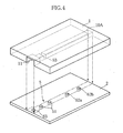
- Figs. 3 and 4 show a fine channel flowmeter according to a second embodiment of the present invention.
- the flow meter A2 of this embodiment differs from that of the first embodiment in that the flowmeter A2 includes a single electrode 62a, a single electrode 62b and a common electrode 63 and further includes a printed wiring board 2 in addition to the main body 1.
- the elements which are identical or similar to those of the first embodiment are designated by the same reference signs as those used for the first embodiment.
- the flowmeterA2 includes the electrode 62a, the electrode 62b and the common electrode 63.
- the structure of the electrodes 62a, 62b is the same as that described as to the flow meter A1.
- the electrodes 62a and 62b are connected to signal lines 74a and 74b via switches 71a and 71b, respectively.
- An end of the common electrode 63 is exposed at the liquid pooling portion 11, whereas the other end of the common electrode is connected to ground.
- the conduction detector 7 detects the electrical conduction between the common electrode 63 and each of the electrodes 62a, 62b.
- the flowmeter A2 of this embodiment is provided in e.g. a cartridge provided by bonding the main body 1 and the printed wiring board 2 together.
- the main body 1 is formed with a groove 10A to serve as a channel 10.
- the printed wiring board 2 comprises a plurality of substrates made of e.g. epoxy resin and laminated together.
- a wiring pattern made of e.g. a copper foil is formed between the substrates.
- the electrodes 62a, 62b and the common electrode 63 are provided in the printed wiring board 2 at portions to face the groove 10A.
- the cartridge is obtained by liquid-tightly bonding the main body 1 and the printed wiring board 2 together using e.g. an adhesive.
- the electrodes 62a, 62b and the common electrode 63 are formed as a so-called through-hole electrode. For instance, as shown in Fig. 5 , the electrode 62a penetrates the printed wiring board 2 in the thickness direction, and the lower end of the electrode is connected to a wiring pattern 22. To prevent undesirable electrical conduction of the wiring pattern 22, a protective sheet is bonded to the lower surface of the printed wiring board 22.
- the switches 71a, 71b are closed to the signal lines 74a, 74b side.
- the front of the blood sample DS reaches the electrode 62a and then the electrode 62b.
- the fact that the front of the blood sample DS has reached the electrodes 62a and 62b is detected based on a change in signals of the signal lines 74a and 74b, respectively.
- the average flow Q12 of the blood sample DS is measured.
- the flow of the blood sample DS through the analysis portion 5 during the analysis by the analysis portion 5 is measured accurately.
- the structure is also suitable for the size reduction of the system including the flowmeter A2.
- the structure of this embodiment includes the single electrode 62a and the single electrode 62b, i.e., the number of electrodes to be formed is small. This is advantageous for reducing the size of the system including the flowmeter A2 and simplifying the process for manufacturing the system. Even with the structure including the single electrode 62a and the single electrode 62b, the fact that the blood sample DS has reached the electrode 62a, 62b is properly detected by detecting the electrical conduction between the common electrode 63 and each of the electrodes 62a and 62b.
- the position of the electrodes 62a, 62b as through-hole electrodes in the printed wiring board 2 can be set relatively accurately. Even when the channel 10 is made narrower, the electrodes 62a, 62b can be arranged at proper positions in the channel 10. Thus, the structure is suitable for reducing the size of the system including the flowmeter A2.
- Fig. 6 shows a fine channel flowmeter according to a third embodiment of the present invention.
- the flowmeter A3 of this embodiment differs from any of the above described embodiments in that the flowmeter A3 includes a plurality of electrode groups 62Aa-62Af.
- the electrode groups 62Aa-62Af are spaced from each other along the flow direction of the channel 10 by a predetermined distance Lc.
- a pair of electrodes 51 is provided to be spaced from the electrode group 62Aa by a distance 2Lc.
- Each of the electrode groups 62Aa-62Af comprises a pair of electrodes 62a-62f.
- the paired electrodes 62a-62f are spaced from each other in a direction perpendicular to the flow direction of the channel 10. For easier understanding, both of the paired electrodes 62a-62f are schematically illustrated to appear in Fig. 6 .
- a connector 21 is provided at an end of the printed wiring board 2.
- the electrode groups 62Aa-62Af and the connector 21 are connected to each other via a wiring pattern (not shown) formed on the lower surface of the printed wiring board 2.
- the connector 21 is connected to the conduction detector 7 via a cable.
- the conduction detector 7 has the same structure as that described with reference to Figs. 1-3 and detects electrical conduction in each of the electrode groups 62Aa-62Af.
- Adjacent ones of the electrode groups 62Aa-62Af are spaced from each other by the distance Lc.
- the flow of the blood sample from when the front of the blood sample DS moves from one of the electrode groups to the adjacent electrode group on the downstream side is equal between any adjacent electrode groups 62Aa-62Af. That is, each time the front of the blood sample reaches one of the electrode groups 62Aa-62Af, it is determined that a predetermined amount of blood sample DS has flowed.
- the counting of blood cells per unit volume of the blood sample DS is performed a plurality of times.
- the flow measurement can be successively performed a plurality of times while counting the blood cells by the analysis portion 5.
- the accuracy of measurement of the blood cells per unit volume of the blood sample DS is enhanced.
- the blood cells is properly counted when the blood sample DS reaches at least the electrode group 62Ab.
- the range of the amount of the blood sample DS to which the system including the flowmeter A3 is applicable is widened.
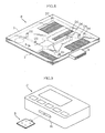
- Figs. 7 and 8 show an example of analyzer cartridge according to the present invention.
- the cartridge B shown in the figures is provided by bonding a main body 1 and a printed wiring board 2 together.
- the cartridge includes a liquid introduction port 3, a dilution means 4, a plurality of analysis portions 5A, 5B, 5C, 5D and two flow measuring units 6A and 6B.
- the two flow measuring units 6A and 6B constitute the fine channel flowmeter according to the present invention.
- the cartridge 9 is loaded into a loading port 81 of an analyzer C.
- the analyzer C is provided with a conduction detector which is similar to the conduction detector 7 shown in Figs. 1 and 3 .
- the main body 1 has a flat rectangular configuration and is made of a transparent resin such as acrylic resin.
- the lower surface of the main body 1 in Fig. 8 is formed with a plurality of recesses or grooves for forming channels or tanks, which will be described later.
- the main body 1 has a size of about 70 mm square and a thickness of about 3 mm.
- the printed wiring board 2 is formed with a plurality of electrodes 51, 62.
- the printed wiring board 2 has an extension provided with a connector 8.
- the connector 8 is utilized for connecting the cartridge B to the analyzer C.
- the liquid introduction port 3 is provided for introducing the blood to be analyzed into the cartridge B.
- the liquid introduction port 3 comprises a through-hole formed in the main body 1 and has a diameter of about 3 mm.
- the dilution means 4 is provided for diluting the blood introduced from the liquid introduction port 3 to a concentration suitable for various kinds of analysis.
- the dilution means includes a diluent tank 41, a first and a second dilution tanks 42A, 42B, a blood measurer 43 and a diluent measurer 44.
- the dilution means 4 of this embodiment is designed to perform two-stage dilution using the first and the second dilution tanks 42A and 42B, which will be described later.
- the diluent tank 41 is provided for storing diluent 40 for diluting the blood in the cartridge B.
- the diluent tank 41 has a diameter of about 12 mm and a depth of about 2 mm and is capable of storing about 200 ⁇ L of diluent 40.
- the blood measurer 43 is arranged between the liquid introduction port 3 and the first dilution tank 42A and includes an introduction channel 43a, a measurement channel 43c, and an overflow channel 43d.
- the introduction channel 43a is used for introducing blood from the liquid introduction port 3.
- the introduction channel 43a has a width of about 250 ⁇ m and a depth of about 250 ⁇ m, so that the width/depth is one. Unless otherwise described, each of the channels described below has the same width and depth as those of the introduction channel 43a.
- the measurement channel 43c and the overflow channel 43d extend from the introduction channel 43a via a branch portion 43b.
- the measurement channel 43c is used for temporarily retaining blood by the amount suitable for the analysis.
- the measurement channel 43c has a length of about 8 mm and a volume of about 0.5 ⁇ L.
- An orifice 43e is provided between the measurement channel 43c and the first dilution tank 42A.
- the orifice 43e serves to increase the pressure drop resistance from the measurement channel 43c to the first dilution tank 42A.
- the overflow channel 43d is a meandering path and connected to a drain D1.
- the diluent measurer 44 is arranged downstream from the diluent tank 41 and connected to the first and the second dilution tanks 42A and 42B.
- the diluent measurer 44 includes an introduction channel 44a, a measurement channel 44c, and an overflow channel 44d.
- the introduction channel 44a is utilized for introducing the diluent 40 from the diluent tank 41.
- the measurement channel 44c and the overflow channel 44d extend from the introduction channel 44a via a branch portion 44b.
- the measurement channel 44c is used for temporarily retaining the diluent 40 by a precise amount suitable for diluting the blood to a predetermined concentration.
- the measurement channel 44c includes a large cross-sectional portion 44ca and two tapered portions 44cb.
- the large cross-sectional portion 44ca has a width of about 2 mm and a depth of about 2 mm, and the volume is about 50 ⁇ L.
- the two tapered portions 44cb are connected respectively to the front end and the rear end of the large cross-sectional portion 44ca and prevent the flow of the diluent 40 into and out of the large cross-sectional portion 44ca from being disturbed.
- the overflow channel 44d is connected to a drain D2.
- Both of the first and the second dilution tanks 42A and 42B are used for diluting blood and have a diameter of about 6 mm, a depth of about 2 mm and a volume of not less than 50 ⁇ L.
- the first dilution tank 42A is connected to the blood measurer 43 and the diluent measurer 44.
- the blood measured by the blood measurer 43 is diluted in the first dilution tank 42A with the diluent 40 measured by the diluent measurer 44.
- the second dilution tank 42B is connected to the first dilution tank 42A and the diluent measurer 44.
- the blood sample diluted in the first dilution tank 42A is diluted in the second dilution tank 42B with the diluent 40 measured by the diluent measurer 44.
- a measurement channel 46 is provided between the first dilution tank 42A and the second dilution tank 42B.
- the analysis portions 5A, 5B, 5C, 5D are portions to perform the analysis of a particular component in the blood.
- the first and the second analysis portions 5A and 5B are designed to perform the analysis by electrical resistance measurement.
- the first analysis portion 5A is for white blood cells, whereas the second analysis portion 5B is for red blood cells.
- the third and the fourth analysis portions 5C and 5D are designed to perform analysis by an optical method.
- the third analysis portion 5C is for Hb, whereas the fourth analysis portion is for CRP.
- the first analysis portion 5A is connected to the first dilution tank 42A via a buffer tank 45.
- the white blood cells are counted in the first analysis portion 5A by using the blood sample diluted in the first dilution tank 42A.
- the first analysis portion 5A includes a hole 53 and a pair of electrodes 51 arranged on the opposite sides of the hole 53 to perform the counting by electrical resistance measurement. While the width of the channel on the opposite sides of the hole 53 is about 250 ⁇ m, the hole 53 has a relatively small width of about 50 ⁇ m.
- the channel includes portions enlarged into a generally circular shape on the opposite sides of the hole 53, at which the paired electrodes 51 are provided.
- the second analysis portion 5B is connected to the second dilution tank 42B.
- the red blood cells are counted in the second analysis portion 5B by using the blood sample after the second dilution in the second dilution tank 42B.
- the structure of the second analysis portion 5B is substantially the same as that of the first analysis portion 5A.
- the buffer tank 45 is provided with a common electrode 63.
- Each of the third and the fourth analysis portions 5C and 5D is independently connected to the buffer tank 45.
- Each of the third and the fourth analysis portions 5C and 5D includes a reflection film 55 provided at a portion of the channel enlarged into a generally circular shape.
- the third and the fourth analysis portions are designed to measure Hb and CRP, respectively, byanopticalmethod. Inthis embodiment, light impinges on the third and the fourth analysis portions 5C and 5D through the main body 1, which is transparent. By detecting the reflected light, Hb and CRP are measured.
- the flow measuring units 6A and 6B are connected to the first and the second analysis portions 5A and 5B, respectively.
- the flow measuring units 6A and 6B measure the flow of the blood sample through the first and the second analysis portions 5A and 5B, respectively.
- Each of the flow measuring units includes a meandering channel 61 and a plurality of electrodes 62.
- the meandering channel 61 is provided to increase the length in the flow direction and has a sufficient volume.
- the meandering channel 61 serves as a storage means capable of storing at least 50 ⁇ L of blood sample after the analysis at the first or the second analysis portion 5A or 5B.
- the plurality of electrodes 62 are arranged at a predetermined pitch in the flow direction of the meandering channel 61.
- the electrodes 62 are connected to the conduction detector (not shown) described in the first through the third embodiments.
- Fig. 7 blood as the sample liquid is introduced into the cartridge from the liquid introduction port 3 by using e.g. a dropper.
- Fig. 9 the cartridge B, into which blood is introduced, is mounted to an analyzer C.
- the connector 8 is connected to a connector (now shown) of the analyzer C.
- the blood is measured by the blood measurer 43.
- a predetermined amount i.e., about 0.5 ⁇ L of blood is retained in the first dilution tank 42A.
- the diluent 40 is measured by the diluent measurer 44.
- a predetermined amount i.e., about 50 ⁇ L of diluent 40a is retained in the first dilution tank 42A.
- about 0.5 ⁇ L of blood and about 50 ⁇ L of diluent 40a are mixed within the first dilution tank 42A to provide blood sample as a 1: 100 diluted sample liquid.
- the mixing may be performed by rotating a stirrer (not shown) incorporated in the first dilution tank 42A within the first dilution tank 42A by utilizing magnetic force.
- the above-described dilution is hereinafter referred to as the first dilution.
- the white blood cells are counted in the first analysis portion 5A, and Hb and CRP are measured in the third and the fourth analysis portions 5C and 5D.
- the buffer tank 45 is connected to the first dilution tank 42A. The above-described 1:100 diluted blood sample is supplied to the buffer tank 45.
- Fig. 10 shows the state to start the counting of the white blood cells.
- the blood sample DS as the 1:100 diluted sample liquid is retained in the buffer tank 45.
- suction of air from e.g. the drain D4 is started.
- the blood sample DS flows out of the buffer tank 45 to flow through the first analysis portion 5A.
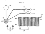
- the front of the blood sample DS reaches the electrode 62a which is positioned on the most upstream side among the plurality of electrodes 62, as shown in Fig. 12 .
- the fact that the front of the blood sample DS has reached the electrode 62a is detected by monitoring the electrical conduction between the common electrode 63 and the electrode 62a. Based on the detection, the counting of the white blood cells by the first analysis portion 5A is started.
- the front of the blood sample DS reaches the electrode 62b which is the second among the plurality of electrodes 62 from the upstream side, as shown in Fig. 13 .
- the reaching is detected by monitoring the electrical conduction between the common electrode 63 and the electrode 62b, for example.
- the flow of the blood sample DS through the first analysis portion 5A during the period from when the front of the blood sample DS reaches the electrode 62a until the front reaches the electrode 62b is equal to the amount of the blood sample DS which can be retained between the electrodes 62a and 62b. Since the distance between the electrodes 62a and 62b along the flow direction is known, the flow of the blood sample DS which has passed through the first analysis portion 5A is determined. Based on this flow and the integrated number of white blood cells, the number of white blood cells per unit volume of the blood sample DS is determined. Based on this, the number of white blood cells per unit volume of the blood is determined.
- the counting may be repeated while continuing the suction to increase the accuracy of the counting.
- the first flow measuring unit 6A is provided with a plurality of electrodes 62. Therefore, the counting can be performed a plurality of times by storing the number of white blood cells every time the front of the blood sample DS reaches each of the electrodes 62 on the downstream side of the electrodes 62a, 62b. This is equivalent to the counting of the white blood cells using a larger amount of blood sample DS, so that the accuracy of counting is enhanced.
- the counting by the first analysis portion 5A may be stopped when it is detected that the front of the blood sample DS has reached the electrode 62n located on the most downstream side among the electrodes 62, as shown in Fig. 14 . As will be understood from the figure, when the counting by the first analysis portion 5A is finished, the blood sample DS after the analysis remains within the meandering channel 61.
- the analysis by the third and the fourth analysis portions 5C and 5D may be performed by performing suction from the drains D5 and D6 to cause the blood sample DS to reach the respective reflection films 55 of the third and the fourth analysis portions 5C and 5D after the counting by the first analysis portion 5A is finished.
- the second dilution is performed by the dilution means 4 shown in Fig. 7 .
- the blood is diluted about 1:100 with the diluent 40.
- the 1:100 diluted blood sample DS obtained by the first dilution is further diluted about 1:100 with the diluent 40.
- substantially 1:10000 dilution is performed using 5 ⁇ L of blood sample DS and about 50 ⁇ L of diluent 40.
- the red blood cells are counted by the second analysis portion 5B using the 1:10000 diluted blood sample obtained by the above-described process.
- the counting is performed in a substantially same manner as the counting performed by the first analysis portion 5A.
- the measurement of the flow utilizing the second flow measuring unit 6B is performed similarly to that utilizing the first flow measuring unit 6A.
- the flow measurement using the first and the second flow measuring units 6A and 6B is very easy and accurate.
- the counting of red blood cells and white blood cells is performed accurately.
- the flow of e.g. the blood sample DS is measured accurately even when the flow of the blood sample DS varies with time.
- the holes 53 of the analysis portions 5A, 5B cause large pressure drop. It is difficult to cause fluid to flow at a constant flow rate through the channel including the portion with a large pressure drop. According to this embodiment, however, it is unnecessary to achieve a constant flow rate, which is suitable for performing the analysis using the analysis portions 5A, 5B including the holes 53.
- the cartridge B does not include a part for flow measurement such as an optical part which cannot be easily reduced in size.
- the use of a flowmeter utilizing an electrode is advantageous for the size reduction of the cartridge B.
- the cartridge B can be suitably designed as a disposable cartridge.
- the fine channel flowmeter, the analyzer using the flowmeter and the analyzer cartridge according to the present invention are not limited to the foregoing embodiments.
- the specific structure of each part of the fine channel flowmeter, the analyzer using the flowmeter and the analyzer cartridge according to the present invention may be varied in design in many ways.
- the number of electrode groups or electrodes is not limited to the above-described embodiments and may be determined depending on e. g. the kind of the fluid as the target of the flow measurement or the structure of the channel.
- the material of the main body is not limited to a transparent one but may be partially opaque. In this case, at least the portion corresponding to the optical analysis portion is made transparent. Although the use of a printed wiring board is preferable for thickness reduction, a rigid substrate may be used.
- the analyzer and the analyzer cartridge according to the present invention are not limited to those having a function to count blood cells and may be designed to analyze various kinds of sample liquid.
Priority Applications (1)
| Application Number | Priority Date | Filing Date | Title |
|---|---|---|---|
| EP11156099A EP2325614A1 (fr) | 2005-09-06 | 2006-09-06 | Débitmètre de canal étroit, et analyseur et cartouche d analyseur l'utilisant |
Applications Claiming Priority (2)
| Application Number | Priority Date | Filing Date | Title |
|---|---|---|---|
| JP2005258174 | 2005-09-06 | ||
| PCT/JP2006/317608 WO2007029720A1 (fr) | 2005-09-06 | 2006-09-06 | Débitmètre de canal étroit, et analyseur et cartouche d’analyseur l’utilisant |
Related Child Applications (1)
| Application Number | Title | Priority Date | Filing Date |
|---|---|---|---|
| EP11156099.1 Division-Into | 2011-02-25 |
Publications (3)
| Publication Number | Publication Date |
|---|---|
| EP1930701A1 true EP1930701A1 (fr) | 2008-06-11 |
| EP1930701A4 EP1930701A4 (fr) | 2008-12-31 |
| EP1930701B1 EP1930701B1 (fr) | 2012-07-11 |
Family
ID=37835839
Family Applications (2)
| Application Number | Title | Priority Date | Filing Date |
|---|---|---|---|
| EP06797504A Active EP1930701B1 (fr) | 2005-09-06 | 2006-09-06 | Cartouche d'analyseur utilisant un débitmètre de canal étroit |
| EP11156099A Withdrawn EP2325614A1 (fr) | 2005-09-06 | 2006-09-06 | Débitmètre de canal étroit, et analyseur et cartouche d analyseur l'utilisant |
Family Applications After (1)
| Application Number | Title | Priority Date | Filing Date |
|---|---|---|---|
| EP11156099A Withdrawn EP2325614A1 (fr) | 2005-09-06 | 2006-09-06 | Débitmètre de canal étroit, et analyseur et cartouche d analyseur l'utilisant |
Country Status (5)
| Country | Link |
|---|---|
| US (1) | US7757568B2 (fr) |
| EP (2) | EP1930701B1 (fr) |
| JP (1) | JP5155661B2 (fr) |
| CN (1) | CN101258386B (fr) |
| WO (1) | WO2007029720A1 (fr) |
Cited By (1)
| Publication number | Priority date | Publication date | Assignee | Title |
|---|---|---|---|---|
| DE102012102979A1 (de) * | 2012-04-05 | 2013-10-24 | Endress + Hauser Flowtec Ag | Durchflussmessgerät, Messrohr sowie Verfahren zur Herstellung eines Durchflussmessgeräts |
Families Citing this family (14)
| Publication number | Priority date | Publication date | Assignee | Title |
|---|---|---|---|---|
| WO2008041900A1 (fr) * | 2006-10-06 | 2008-04-10 | Boule Medical Ab | dispositif d'extraction d'un volume partiel défini d'échantillon À PARTIR D'un volume d'entreposage, procédé de commande du dispositif, ensemble d'au moins deux dispositifs, procédé d'utilisation de l'ensemble, instrument analytique apte à être relié au dispositif, procédé d'utilisation de l'instrument, système et procédé d |
| CN102822680B (zh) | 2010-03-25 | 2015-10-21 | 恩德莱斯和豪瑟尔测量及调节技术分析仪表两合公司 | 用于处理液体的系统 |
| DE102010030489A1 (de) | 2010-03-25 | 2011-09-29 | Endress + Hauser Conducta Gesellschaft für Mess- und Regeltechnik mbH + Co. KG | System zu Behandlung von Flüssigkeiten |
| USD673286S1 (en) * | 2010-04-29 | 2012-12-25 | Sony Corporation | Micro flow channel chip |
| USD869308S1 (en) | 2010-04-29 | 2019-12-10 | Sony Corporation | Micro flow channel chip |
| USD673287S1 (en) | 2010-11-24 | 2012-12-25 | Sony Corporation | Micro flow channel chip |
| CN105342553B (zh) * | 2010-06-30 | 2019-05-07 | 安派科生物医学科技有限公司 | 疾病检测仪 |
| BR112016029490B1 (pt) | 2014-06-18 | 2021-06-15 | Scandinavian Micro Biodevices Aps | Sistema de detecção microfluídica |
| JP6433804B2 (ja) * | 2015-02-09 | 2018-12-05 | 株式会社東芝 | マイクロ分析パッケージ及びパッケージ基板 |
| SG11201912711XA (en) * | 2017-11-07 | 2020-01-30 | Takasago Elec Inc | Fluid device |
| JP6708978B2 (ja) * | 2017-12-28 | 2020-06-10 | ソニー株式会社 | マイクロチップ及び微小粒子分析装置 |
| DE102018204615A1 (de) * | 2018-03-27 | 2019-10-02 | Robert Bosch Gmbh | Sensoranordnung für ein Fahrzeug |
| EP4301238A1 (fr) * | 2021-03-03 | 2024-01-10 | Withings | Capteur de volume et de débit, injecteur associé |
| JP6948047B1 (ja) * | 2021-06-20 | 2021-10-13 | アットドウス株式会社 | 薬液投与装置、薬液管理装置、薬液管理システム、薬液管理プログラム、記録媒体、及び薬液管理方法 |
Citations (4)
| Publication number | Priority date | Publication date | Assignee | Title |
|---|---|---|---|---|
| US3820392A (en) * | 1971-04-15 | 1974-06-28 | Fielden Electronics Ltd | Measurement of flow in a hydraulic system |
| US4559831A (en) * | 1983-09-26 | 1985-12-24 | Siemens Aktiengesellschaft | Method and device for flow measurement of small liquid volumes |
| US5220920A (en) * | 1991-11-08 | 1993-06-22 | Via Medical Corporation | Electrochemical measurement system having interference reduction circuit |
| US20020092363A1 (en) * | 2001-01-16 | 2002-07-18 | Jorgenson James W. | Contactless resistive heater for liquids in microenvironments and related methods |
Family Cites Families (6)
| Publication number | Priority date | Publication date | Assignee | Title |
|---|---|---|---|---|
| JPS5794625A (en) | 1980-11-19 | 1982-06-12 | Takaoka Kogyo Kk | Measuring device for temperature of molten metal and time |
| JPS6033055A (ja) | 1983-08-01 | 1985-02-20 | Daido Steel Co Ltd | 鋳造品の湯流れ試験装置 |
| US6122956A (en) * | 1998-09-09 | 2000-09-26 | University Of Florida | Method and apparatus for monitoring concentration of a slurry flowing in a pipeline |
| US7144485B2 (en) * | 2003-01-13 | 2006-12-05 | Hmd Biomedical Inc. | Strips for analyzing samples |
| JP2005140756A (ja) | 2003-11-10 | 2005-06-02 | Kanagawa Acad Of Sci & Technol | 微細流路用流速計とマイクロチップ並びにマイクロ流体操作機器 |
| US20050118061A1 (en) * | 2003-11-28 | 2005-06-02 | Sysmex Corporation | Analyzer, assay cartridge and analyzing method |
-
2006
- 2006-09-06 WO PCT/JP2006/317608 patent/WO2007029720A1/fr active Application Filing
- 2006-09-06 US US11/991,580 patent/US7757568B2/en active Active
- 2006-09-06 CN CN2006800324324A patent/CN101258386B/zh active Active
- 2006-09-06 EP EP06797504A patent/EP1930701B1/fr active Active
- 2006-09-06 JP JP2007534439A patent/JP5155661B2/ja active Active
- 2006-09-06 EP EP11156099A patent/EP2325614A1/fr not_active Withdrawn
Patent Citations (4)
| Publication number | Priority date | Publication date | Assignee | Title |
|---|---|---|---|---|
| US3820392A (en) * | 1971-04-15 | 1974-06-28 | Fielden Electronics Ltd | Measurement of flow in a hydraulic system |
| US4559831A (en) * | 1983-09-26 | 1985-12-24 | Siemens Aktiengesellschaft | Method and device for flow measurement of small liquid volumes |
| US5220920A (en) * | 1991-11-08 | 1993-06-22 | Via Medical Corporation | Electrochemical measurement system having interference reduction circuit |
| US20020092363A1 (en) * | 2001-01-16 | 2002-07-18 | Jorgenson James W. | Contactless resistive heater for liquids in microenvironments and related methods |
Non-Patent Citations (1)
| Title |
|---|
| See also references of WO2007029720A1 * |
Cited By (2)
| Publication number | Priority date | Publication date | Assignee | Title |
|---|---|---|---|---|
| DE102012102979A1 (de) * | 2012-04-05 | 2013-10-24 | Endress + Hauser Flowtec Ag | Durchflussmessgerät, Messrohr sowie Verfahren zur Herstellung eines Durchflussmessgeräts |
| US9658088B2 (en) | 2012-04-05 | 2017-05-23 | Endress + Hauser Flowtec Ag | Flow measuring device, measuring tube as well as method for manufacture of a flow measuring device |
Also Published As
| Publication number | Publication date |
|---|---|
| EP1930701B1 (fr) | 2012-07-11 |
| JPWO2007029720A1 (ja) | 2009-03-19 |
| US20090126505A1 (en) | 2009-05-21 |
| EP1930701A4 (fr) | 2008-12-31 |
| US7757568B2 (en) | 2010-07-20 |
| JP5155661B2 (ja) | 2013-03-06 |
| CN101258386A (zh) | 2008-09-03 |
| WO2007029720A1 (fr) | 2007-03-15 |
| EP2325614A1 (fr) | 2011-05-25 |
| CN101258386B (zh) | 2011-11-16 |
Similar Documents
| Publication | Publication Date | Title |
|---|---|---|
| EP1930701B1 (fr) | Cartouche d'analyseur utilisant un débitmètre de canal étroit | |
| JP2007003414A (ja) | 分析装置用カートリッジ | |
| JP4660662B2 (ja) | カートリッジ | |
| JP2685544B2 (ja) | 血液フィルタおよび血液検査方法並びに血液検査装置 | |
| US11035784B2 (en) | Methods and systems for optical hemoglobin measurement | |
| US8172455B2 (en) | Liquid feeding method and cartridge to be used therein | |
| US8616048B2 (en) | Reusable thin film particle sensor | |
| JP5059880B2 (ja) | フローセル | |
| US8804105B2 (en) | Combined optical imaging and electrical detection to characterize particles carried in a fluid | |
| EP1898222A1 (fr) | Cartouche | |
| US20090107909A1 (en) | Microchannel for Separating Blood Plasma | |
| US20100288941A1 (en) | Fluorescence-based pipette instrument | |
| CN103969170A (zh) | 具有集成光学器件的微成型血细胞计数器卡 | |
| US8663578B2 (en) | Tank for introducing liquid drop thereinto and analyzing device | |
| EP3859346A1 (fr) | Procédé d'introduction d'un échantillon dans un dispositif de traitement d'échantillon | |
| JP2007047031A (ja) | 分析方法および分析用具 | |
| US9952135B2 (en) | Microfluidic interrogation device | |
| CN212228679U (zh) | 测量单细胞细胞膜水利渗透性系数的微装置 | |
| US20180335376A1 (en) | Microfluidic interrogation device |
Legal Events
| Date | Code | Title | Description |
|---|---|---|---|
| PUAI | Public reference made under article 153(3) epc to a published international application that has entered the european phase |
Free format text: ORIGINAL CODE: 0009012 |
|
| 17P | Request for examination filed |
Effective date: 20080312 |
|
| AK | Designated contracting states |
Kind code of ref document: A1 Designated state(s): AT BE BG CH CY CZ DE DK EE ES FI FR GB GR HU IE IS IT LI LT LU LV MC NL PL PT RO SE SI SK TR |
|
| A4 | Supplementary search report drawn up and despatched |
Effective date: 20081128 |
|
| RIC1 | Information provided on ipc code assigned before grant |
Ipc: G01P 5/18 20060101ALI20081124BHEP Ipc: G01F 1/64 20060101ALI20081124BHEP Ipc: G01F 1/708 20060101AFI20070524BHEP Ipc: G01N 35/08 20060101ALI20081124BHEP Ipc: G01N 15/14 20060101ALI20081124BHEP Ipc: G01N 37/00 20060101ALI20081124BHEP Ipc: G01F 1/00 20060101ALI20081124BHEP Ipc: G01N 15/12 20060101ALI20081124BHEP |
|
| 17Q | First examination report despatched |
Effective date: 20090227 |
|
| GRAP | Despatch of communication of intention to grant a patent |
Free format text: ORIGINAL CODE: EPIDOSNIGR1 |
|
| RTI1 | Title (correction) |
Free format text: ANALYZER CARTRIDGE THAT USES A FINE CHANNEL FLOWMETER |
|
| DAX | Request for extension of the european patent (deleted) | ||
| GRAS | Grant fee paid |
Free format text: ORIGINAL CODE: EPIDOSNIGR3 |
|
| GRAA | (expected) grant |
Free format text: ORIGINAL CODE: 0009210 |
|
| AK | Designated contracting states |
Kind code of ref document: B1 Designated state(s): AT BE BG CH CY CZ DE DK EE ES FI FR GB GR HU IE IS IT LI LT LU LV MC NL PL PT RO SE SI SK TR |
|
| REG | Reference to a national code |
Ref country code: GB Ref legal event code: FG4D |
|
| REG | Reference to a national code |
Ref country code: CH Ref legal event code: EP |
|
| REG | Reference to a national code |
Ref country code: AT Ref legal event code: REF Ref document number: 566363 Country of ref document: AT Kind code of ref document: T Effective date: 20120715 |
|
| REG | Reference to a national code |
Ref country code: IE Ref legal event code: FG4D |
|
| REG | Reference to a national code |
Ref country code: DE Ref legal event code: R096 Ref document number: 602006030737 Country of ref document: DE Effective date: 20120906 |
|
| REG | Reference to a national code |
Ref country code: NL Ref legal event code: VDEP Effective date: 20120711 |
|
| REG | Reference to a national code |
Ref country code: AT Ref legal event code: MK05 Ref document number: 566363 Country of ref document: AT Kind code of ref document: T Effective date: 20120711 |
|
| REG | Reference to a national code |
Ref country code: LT Ref legal event code: MG4D Effective date: 20120711 |
|
| PG25 | Lapsed in a contracting state [announced via postgrant information from national office to epo] |
Ref country code: AT Free format text: LAPSE BECAUSE OF FAILURE TO SUBMIT A TRANSLATION OF THE DESCRIPTION OR TO PAY THE FEE WITHIN THE PRESCRIBED TIME-LIMIT Effective date: 20120711 Ref country code: BE Free format text: LAPSE BECAUSE OF FAILURE TO SUBMIT A TRANSLATION OF THE DESCRIPTION OR TO PAY THE FEE WITHIN THE PRESCRIBED TIME-LIMIT Effective date: 20120711 Ref country code: IS Free format text: LAPSE BECAUSE OF FAILURE TO SUBMIT A TRANSLATION OF THE DESCRIPTION OR TO PAY THE FEE WITHIN THE PRESCRIBED TIME-LIMIT Effective date: 20121111 Ref country code: LT Free format text: LAPSE BECAUSE OF FAILURE TO SUBMIT A TRANSLATION OF THE DESCRIPTION OR TO PAY THE FEE WITHIN THE PRESCRIBED TIME-LIMIT Effective date: 20120711 Ref country code: CY Free format text: LAPSE BECAUSE OF FAILURE TO SUBMIT A TRANSLATION OF THE DESCRIPTION OR TO PAY THE FEE WITHIN THE PRESCRIBED TIME-LIMIT Effective date: 20120711 Ref country code: FI Free format text: LAPSE BECAUSE OF FAILURE TO SUBMIT A TRANSLATION OF THE DESCRIPTION OR TO PAY THE FEE WITHIN THE PRESCRIBED TIME-LIMIT Effective date: 20120711 |
|
| PG25 | Lapsed in a contracting state [announced via postgrant information from national office to epo] |
Ref country code: SI Free format text: LAPSE BECAUSE OF FAILURE TO SUBMIT A TRANSLATION OF THE DESCRIPTION OR TO PAY THE FEE WITHIN THE PRESCRIBED TIME-LIMIT Effective date: 20120711 Ref country code: LV Free format text: LAPSE BECAUSE OF FAILURE TO SUBMIT A TRANSLATION OF THE DESCRIPTION OR TO PAY THE FEE WITHIN THE PRESCRIBED TIME-LIMIT Effective date: 20120711 Ref country code: GR Free format text: LAPSE BECAUSE OF FAILURE TO SUBMIT A TRANSLATION OF THE DESCRIPTION OR TO PAY THE FEE WITHIN THE PRESCRIBED TIME-LIMIT Effective date: 20121012 Ref country code: SE Free format text: LAPSE BECAUSE OF FAILURE TO SUBMIT A TRANSLATION OF THE DESCRIPTION OR TO PAY THE FEE WITHIN THE PRESCRIBED TIME-LIMIT Effective date: 20120711 Ref country code: PT Free format text: LAPSE BECAUSE OF FAILURE TO SUBMIT A TRANSLATION OF THE DESCRIPTION OR TO PAY THE FEE WITHIN THE PRESCRIBED TIME-LIMIT Effective date: 20121112 Ref country code: PL Free format text: LAPSE BECAUSE OF FAILURE TO SUBMIT A TRANSLATION OF THE DESCRIPTION OR TO PAY THE FEE WITHIN THE PRESCRIBED TIME-LIMIT Effective date: 20120711 |
|
| PG25 | Lapsed in a contracting state [announced via postgrant information from national office to epo] |
Ref country code: NL Free format text: LAPSE BECAUSE OF FAILURE TO SUBMIT A TRANSLATION OF THE DESCRIPTION OR TO PAY THE FEE WITHIN THE PRESCRIBED TIME-LIMIT Effective date: 20120711 |
|
| PG25 | Lapsed in a contracting state [announced via postgrant information from national office to epo] |
Ref country code: RO Free format text: LAPSE BECAUSE OF FAILURE TO SUBMIT A TRANSLATION OF THE DESCRIPTION OR TO PAY THE FEE WITHIN THE PRESCRIBED TIME-LIMIT Effective date: 20120711 Ref country code: DK Free format text: LAPSE BECAUSE OF FAILURE TO SUBMIT A TRANSLATION OF THE DESCRIPTION OR TO PAY THE FEE WITHIN THE PRESCRIBED TIME-LIMIT Effective date: 20120711 Ref country code: MC Free format text: LAPSE BECAUSE OF NON-PAYMENT OF DUE FEES Effective date: 20120930 Ref country code: ES Free format text: LAPSE BECAUSE OF FAILURE TO SUBMIT A TRANSLATION OF THE DESCRIPTION OR TO PAY THE FEE WITHIN THE PRESCRIBED TIME-LIMIT Effective date: 20121022 Ref country code: EE Free format text: LAPSE BECAUSE OF FAILURE TO SUBMIT A TRANSLATION OF THE DESCRIPTION OR TO PAY THE FEE WITHIN THE PRESCRIBED TIME-LIMIT Effective date: 20120711 Ref country code: CZ Free format text: LAPSE BECAUSE OF FAILURE TO SUBMIT A TRANSLATION OF THE DESCRIPTION OR TO PAY THE FEE WITHIN THE PRESCRIBED TIME-LIMIT Effective date: 20120711 |
|
| REG | Reference to a national code |
Ref country code: CH Ref legal event code: PL |
|
| PLBE | No opposition filed within time limit |
Free format text: ORIGINAL CODE: 0009261 |
|
| STAA | Information on the status of an ep patent application or granted ep patent |
Free format text: STATUS: NO OPPOSITION FILED WITHIN TIME LIMIT |
|
| PG25 | Lapsed in a contracting state [announced via postgrant information from national office to epo] |
Ref country code: SK Free format text: LAPSE BECAUSE OF FAILURE TO SUBMIT A TRANSLATION OF THE DESCRIPTION OR TO PAY THE FEE WITHIN THE PRESCRIBED TIME-LIMIT Effective date: 20120711 |
|
| 26N | No opposition filed |
Effective date: 20130412 |
|
| REG | Reference to a national code |
Ref country code: IE Ref legal event code: MM4A |
|
| PG25 | Lapsed in a contracting state [announced via postgrant information from national office to epo] |
Ref country code: IE Free format text: LAPSE BECAUSE OF NON-PAYMENT OF DUE FEES Effective date: 20120906 Ref country code: BG Free format text: LAPSE BECAUSE OF FAILURE TO SUBMIT A TRANSLATION OF THE DESCRIPTION OR TO PAY THE FEE WITHIN THE PRESCRIBED TIME-LIMIT Effective date: 20121011 Ref country code: CH Free format text: LAPSE BECAUSE OF NON-PAYMENT OF DUE FEES Effective date: 20120930 Ref country code: LI Free format text: LAPSE BECAUSE OF NON-PAYMENT OF DUE FEES Effective date: 20120930 |
|
| REG | Reference to a national code |
Ref country code: DE Ref legal event code: R097 Ref document number: 602006030737 Country of ref document: DE Effective date: 20130412 |
|
| PG25 | Lapsed in a contracting state [announced via postgrant information from national office to epo] |
Ref country code: TR Free format text: LAPSE BECAUSE OF FAILURE TO SUBMIT A TRANSLATION OF THE DESCRIPTION OR TO PAY THE FEE WITHIN THE PRESCRIBED TIME-LIMIT Effective date: 20120711 |
|
| PG25 | Lapsed in a contracting state [announced via postgrant information from national office to epo] |
Ref country code: LU Free format text: LAPSE BECAUSE OF NON-PAYMENT OF DUE FEES Effective date: 20120906 |
|
| PG25 | Lapsed in a contracting state [announced via postgrant information from national office to epo] |
Ref country code: HU Free format text: LAPSE BECAUSE OF FAILURE TO SUBMIT A TRANSLATION OF THE DESCRIPTION OR TO PAY THE FEE WITHIN THE PRESCRIBED TIME-LIMIT Effective date: 20060906 |
|
| REG | Reference to a national code |
Ref country code: FR Ref legal event code: PLFP Year of fee payment: 10 |
|
| REG | Reference to a national code |
Ref country code: FR Ref legal event code: PLFP Year of fee payment: 11 |
|
| REG | Reference to a national code |
Ref country code: FR Ref legal event code: PLFP Year of fee payment: 12 |
|
| REG | Reference to a national code |
Ref country code: FR Ref legal event code: PLFP Year of fee payment: 13 |
|
| PGFP | Annual fee paid to national office [announced via postgrant information from national office to epo] |
Ref country code: GB Payment date: 20230920 Year of fee payment: 18 |
|
| PGFP | Annual fee paid to national office [announced via postgrant information from national office to epo] |
Ref country code: FR Payment date: 20230928 Year of fee payment: 18 Ref country code: DE Payment date: 20230920 Year of fee payment: 18 |
|
| PGFP | Annual fee paid to national office [announced via postgrant information from national office to epo] |
Ref country code: IT Payment date: 20230927 Year of fee payment: 18 |