EP1930634A1 - Brush seal assemblies utilizing a threaded fastening method - Google Patents
Brush seal assemblies utilizing a threaded fastening method Download PDFInfo
- Publication number
- EP1930634A1 EP1930634A1 EP07254738A EP07254738A EP1930634A1 EP 1930634 A1 EP1930634 A1 EP 1930634A1 EP 07254738 A EP07254738 A EP 07254738A EP 07254738 A EP07254738 A EP 07254738A EP 1930634 A1 EP1930634 A1 EP 1930634A1
- Authority
- EP
- European Patent Office
- Prior art keywords
- plate
- threads
- brush seal
- assembly
- retaining
- Prior art date
- Legal status (The legal status is an assumption and is not a legal conclusion. Google has not performed a legal analysis and makes no representation as to the accuracy of the status listed.)
- Withdrawn
Links
- 238000000034 method Methods 0.000 title claims description 18
- 230000000712 assembly Effects 0.000 title description 7
- 238000000429 assembly Methods 0.000 title description 7
- 230000013011 mating Effects 0.000 claims description 8
- 239000000463 material Substances 0.000 description 5
- 238000010586 diagram Methods 0.000 description 4
- 238000010438 heat treatment Methods 0.000 description 4
- 238000003466 welding Methods 0.000 description 4
- 238000004519 manufacturing process Methods 0.000 description 3
- 239000012530 fluid Substances 0.000 description 2
- 239000002184 metal Substances 0.000 description 2
- 229910052751 metal Inorganic materials 0.000 description 2
- 229910000531 Co alloy Inorganic materials 0.000 description 1
- 239000003575 carbonaceous material Substances 0.000 description 1
- 239000000446 fuel Substances 0.000 description 1
- 238000003754 machining Methods 0.000 description 1
- 150000002739 metals Chemical class 0.000 description 1
Images



Classifications
-
- F—MECHANICAL ENGINEERING; LIGHTING; HEATING; WEAPONS; BLASTING
- F16—ENGINEERING ELEMENTS AND UNITS; GENERAL MEASURES FOR PRODUCING AND MAINTAINING EFFECTIVE FUNCTIONING OF MACHINES OR INSTALLATIONS; THERMAL INSULATION IN GENERAL
- F16J—PISTONS; CYLINDERS; SEALINGS
- F16J15/00—Sealings
- F16J15/16—Sealings between relatively-moving surfaces
- F16J15/32—Sealings between relatively-moving surfaces with elastic sealings, e.g. O-rings
- F16J15/3284—Sealings between relatively-moving surfaces with elastic sealings, e.g. O-rings characterised by their structure; Selection of materials
- F16J15/3288—Filamentary structures, e.g. brush seals
-
- Y—GENERAL TAGGING OF NEW TECHNOLOGICAL DEVELOPMENTS; GENERAL TAGGING OF CROSS-SECTIONAL TECHNOLOGIES SPANNING OVER SEVERAL SECTIONS OF THE IPC; TECHNICAL SUBJECTS COVERED BY FORMER USPC CROSS-REFERENCE ART COLLECTIONS [XRACs] AND DIGESTS
- Y10—TECHNICAL SUBJECTS COVERED BY FORMER USPC
- Y10T—TECHNICAL SUBJECTS COVERED BY FORMER US CLASSIFICATION
- Y10T29/00—Metal working
- Y10T29/53—Means to assemble or disassemble
- Y10T29/53657—Means to assemble or disassemble to apply or remove a resilient article [e.g., tube, sleeve, etc.]
Definitions
- the present invention generally relates to brush seals.
- the present invention relates to a brush seal assembly utilizing threaded members.
- Brush seals are commonly used in gas turbine engines and other assemblies to restrict the escape of fluid (i.e. air) through a gap between a stationary part and a rotating part.
- the stationary part may be a diffuser case and the rotating part may be a turbine shaft.
- Brush seals may also be used to seal gaps between two stationary parts or two rotating parts of a gas turbine engine. In either case, minimization of leakage is important in maintaining the efficiency of the system and to reduce fuel consumption.
- a brush seal generally includes packs of wire bristles that are sandwiched between two plates. It is common practice to weld the bristles and plates together. The brush seal must then undergo heat treatment after welding to relieve any residual stresses. Heat treatment typically involves securing the brush seal within a fixture and placing the fixture in an oven. The heat treatment is a time consuming and expensive process.
- the bristles of the brush seal eventually wear and need to be replaced over time. For example, replacement may be scheduled after a given number of hours or cycles of operation.
- replacement may be scheduled after a given number of hours or cycles of operation.
- conventional brush seals are welded assemblies, removal of the brush seal can be difficult.
- individual components of the brush seal are welded together, individual components such as wire bristles cannot easily be replaced.
- replacement of the entire brush seal must occur at significant costs in regards to material labor and down time, even though only one of the subassemblies needs replacement.
- a current method used that allows replacement of individual components of the brush seal is to manufacture the brush seals in subassemblies without plate welding. These brush seals combine the bristles together and sandwich the bristle packs between the plates using clips or fasteners. While these methods are effective, they also require additional machining under relatively close tolerances, thus increasing the overall cost of production.
- a brush seal assembly includes a plurality of bristles, a joint, and a retaining assembly.
- Each of the bristles has a first end and a second end.
- the joint has a first side and a second side and connects the first ends of the bristles.
- the retaining assembly sandwiches the joint and includes a side plate, a back plate, and a threaded connection.
- the side plate engages the first side of the joint and the back plate engages the second side of the joint.
- the threaded connection holds the side plate and the back plate in engagement with the joint.
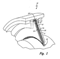
- FIG. 1 shows a perspective, cross-sectional view of a representative brush seal assembly 10.
- Brush seal assembly 10 generally includes bristle assembly 12, side plate 14, and back plate 16. Adjustable pin spanners 18a and 18b (shown in FIG. 3 ) tighten side plate 14 to back plate 16, sandwiching bristle assembly 12 therebetween.
- Bristle assembly 12 has a first side 19 and a second side 20 and is formed of a plurality of densely arranged wire bristles 21.
- bristle assembly 12 is depicted in FIG. 1 as having a full ring shape, bristle assembly 12 may have other shapes without departing from the intended scope of the present invention.
- bristle assembly 12 may have an arcuate, segmented arcuate or linear shape.
- Each of wire bristles 21 has a first end 22 and a second end 24.
- First ends 22 of wire bristles 21 reside at an outer diameter of bristle assembly 12 and are secured together by joint 25, such as a weld, and are generally connected to joint 25 such that wire bristles 21 are angled to a radial line.
- Joint 25 has a first side 26 in line with first side 19 of bristle assembly 12 and a second side 27 in line with second side 20 of bristle assembly 12.
- Second ends 24 of wire bristles 21 extend away from joint 25 and reside at an inner diameter of bristle assembly 12.
- Wire bristles 21 are made of a strong, flexible material.
- wire bristles 21 may be made of an approximately 0.002 inch (0.05 mm) diameter to an approximately 0.006 inch (0.15 mm) diameter cobalt alloy wire.
- first ends of wire bristles 20 are connected to joint 25 such that they are angled at approximately 45 degrees from a radial line.
- FIGS. 2 and 3 show a cross-sectional view and an exploded view, respectively, of a first embodiment of brush seal assembly 10a, and will be discussed in conjunction with one another.
- Bristle assembly 12 is positioned between side plate 14 and back plate 16, all of which are removably connected to one another.
- Pin spanners 18a and 18b are used to assemble side plate 14 and back plate 16 together.
- Side plate 14 provides a front cover to protect bristle assembly 12 and includes first surface 28, second surface 30, inner diameter 32, outer diameter 34, recess 36, first spanner hole 38a, and second spanner hole 38b ( FIG. 3 ).
- Outer diameter 34 of side plate 14 includes outer threads 40.
- Recess 36 is located within second surface 30 of side plate 14 and is sized to accept first side 26 of joint 25 of bristle assembly 12.
- first side 20 of bristle assembly 12 is positioned immediately adjacent second surface 30 of side plate 14.
- a windage cover 42 (shown in FIG. 2 ) may also be integral to side plate 14 at inner diameter 32 of side plate 14.
- side plate 14 is discussed as having two spanner holes 38a and 38b, side plate 14 may have any number of spanner holes around the circumference of side plate 14.
- outer diameter 34 is discussed as including threads 40, any locking feature known in the art may be used.
- Back plate 16 is the primary structural element of brush seal assembly 10a and provides downstream support to brush seal assembly 10a by supporting bristle assembly 12 and preventing bristle blowover due to fluid pressure differential.
- Back plate 16 includes first surface 44, second surface 46, inner diameter 48, outer diameter 50, back cover 52, first spanner hole 54a, second spanner hole 54b, first axial slot 56a, and second axial slot 56b.
- Inner diameter 48 of back plate 16 includes inner threads 58 that are engagable with outer threads 40 of side plate 14. Stress calculations may be performed on threads 40 and 58 of side plate 14 and back plate 16, respectively, to determine the optimum thread size and pitch relative to the size of brush seal assembly 10a and the resistive and compressive axial spring rate of bristle assembly 12.
- Spanner holes 54a and 54b are formed in back cover 52, which extends across second surface 46 of back plate 16.
- Back cover 52 also has a hole 59 in the center of back cover 52 to position a component, such as a shaft or rotor, with clearance.
- back plate 16 is discussed as having two spanner holes 54a and 54b and two axial slots 56a and 56b, back plate 16 may have any number of spanner holes and axial slots around the circumference of back plate 16.
- inner diameter 48 is discussed as including threads 58, any locking feature known in the art may be used.
- Bristle assembly 12, side plate 14, and back plate 16 are assembled together with the use of adjustable pin spanner tools 18a and 18b.
- Adjustable pin spanners 18a and 18b allow the same tool to be used on brush seal assemblies having a range of diameters.
- First adjustable pin spanner 18a generally includes spanner arm 60a, adjustment slot 62a, fixed pin 64a, movable pin 66a, and threaded fastener 68a.
- Second adjustable pin spanner 18b functions and interacts similarly to first adjustable pin spanner 18a and generally includes spanner arm 60b, adjustment slot 62b, fixed pin 64b, movable pin 66b, and threaded fastener 68b.
- Adjustable pin spanners 18a and 18b may optionally include a torque measuring device to assure uniform assembly torques.
- joint 25 and bristle assembly 12 are positioned against second surface 30 of side plate 14 with first side 26 of joint 25 engaging recess 36 (shown in FIG. 2 ) of side plate 14.
- outer threads 40 of side plate 14 are engageable with inner threads 58 of back plate 16, allowing side plate 14 and bristle assembly 12 to fit within inner diameter 48 of back plate 16.
- threads 40 of side plate 14 are threaded into threads 58 of back plate 16 (shown in FIGS. 2 and 3 ).
- Side plate 14 and bristle assembly 12 are threaded within inner diameter 48 of back plate 16 until second side 27 of joint 25 and second side 21 of bristle assembly 12 abuts back cover 52 of back plate 16.
- Second ends 24 of wire bristles 21 extend past inner diameters 32 and 48 of both side plate 14 and back plate 16, respectively, allowing bristle assembly 12 to reach a component, such as a rotor, to form a seal.
- brush seal assembly 10a may optionally include a washer positioned between second surface 30 of side plate 14 and first side 19 of bristle assembly 12, as well as positioned between second side 20 of bristle assembly 12 and first surface 44 of back plate 16.
- the washers would function to protect wire bristles 21 as side plate 14 and back plate 16 spin against bristle assembly 12 during assembly.
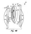
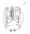
- FIGS. 4A-4C show how first and second adjustable pin spanners 18a and 18b are adjustable to work with different size brush seal assemblies and different spanner slot configurations.
- FIG. 4A shows adjustable pin spanners 18a and 18b in use with spanner holes 38a, 38b, 54a, and 54b of brush seal assembly 10a.
- FIG. 4B shows adjustable pin spanners 18a and 18b in use with spanner slots 38a and 38 and axial slots 56a and 56b of brush seal assembly 10b.
- FIG. 4C shows adjustable pin spanners 18a and 18b in use with brush seal assembly 10c having a smaller diameter than brush seal assemblies 10a and 10b.
- FIG. 4A shows a side view of brush seal assembly 10a.
- first adjustable pin spanner 18a is positioned immediately adjacent first surface 28 of side plate 14.
- Fixed pin 64a of first adjustable pin spanner 18a is aligned with, and engages, first spanner hole 38a of side plate 14.
- Movable pin 66a is then adjusted within adjustment slot 62a until aligned with second spanner hole 38b of side plate 14.
- Movable pin 66a is then positioned within second spanner hole 38b and is maintained in place within adjustment slot 62a by threaded fastener 68a.
- spanner arm 60b of adjustable pin spanner 18b is positioned immediately adjacent second surface 46 of back plate 16 and engages back plate 16 in the same manner that first adjustable pin spanner 18a engages side plate 14.
- adjustable pin spanners 18a and 18b sandwich bristle assembly 12 between side plate 14 and back plate 16, which form brush seal assembly 10a.
- adjustable pin spanners 18a and 18b are turned in opposing directions (as shown by arrows in FIG. 4A ) to tighten side plate 14, bristle assembly 12, and back plate 16 together.
- side plate 14 is turned in the same direction as first adjustable pin spanner 18a and back plate 16 is turned in the same direction as second adjustable pin spanner 18b.
- adjustable pin spanners 18a and 18b may be removed from side plate 14 and back plate 16.
- side plate 14 and back plate 16 may each have more than two spanner holes.
- the additional spanner holes provide leverage for a user turning adjustable pin spanners 18a and 18b and may help facilitate threading of side plate 14 and back plate 16 if clearance is limited.
- the assembler is able to place adjustable pin spanners 18a and 18b at different locations around the circumferences of side plate 14 and back plate 16 as necessary to obtain optimal handling of brush seal assembly 10a.
- FIG. 4B shows a side view of brush seal assembly 10b which generally includes a back plate 70, bristle assembly 12, and side plate 14. While first adjustable pin spanner 18a interacts with side plate 14 in the manner described for brush seal assembly 10a, fixed pin 64b and movable pin 66b of second adjustable pin spanner 18b engage axial slots 56a and 56b of back plate 70. Once fixed pin 64b is positioned within first axial slot 56a, movable pin 66b is adjusted within adjustment slot 62b and aligned with second axial slot 56b. Once fixed pin 64b and movable pin 66b are properly positioned within axial slots 56a and 56b, respectively, brush seal assembly 10b is tightened in a similar manner as brush seal assembly 10a.
- Axial slots 56a and 56b may be used to tighten brush seal assembly 10b if back cover 52 of back plate 70 does not include spanner holes 54a and 54b, if back plate 70 optionally does not include a back cover, or if it is more convenient to use axial slots 56a and 56b.
- side plate 14 may have more than two spanner holes and back plate 16 may have more than two axial slots.
- the additional spanner holes and axial slots function in the same manner as the additional spanner holes in brush seal assembly 10a, providing leverage for a user turning adjustable pin spanners 18a and 18b.
- FIG. 4C shows a side view of brush seal assembly 10c having side plate 72, bristle assembly 74, and back plate 76.
- the components of brush seal assembly 10c interact and function similarly to the components of brush seal assembly 10a described in the discussion of FIG. 4A , except that the outer diameters of side plate 72, bristle assembly 74, and back plate 76 are smaller than the outer diameters of side plate 14, bristle assembly 12, and back plate 16 (shown in FIG. 4A ). Because the diameters of brush seal assembly 10c are smaller than the diameters brush seal assembly 10a, movable pins 66a and 66b of first and second adjustable pin spanners 18a and 18b must be accordingly adjusted.
- Movable pins 66a and 66b are adjusted within adjustment slots 62a and 62b, respectively, until first movable pin 66a is engagable with second spanner hole 38b of side plate 72 and second movable pin 66b is engagable with second spanner hole 54b of back plate 76.
- brush seal assembly 10c is tightened by first and second adjustable pin spanners 18a and 18b in the same manner as side brush seal assembly 10a.
- FIG. 4C depicts a brush seal assembly having a smaller diameter than brush seal assembly 10a, brush seal assemblies of any diameter may be joined together using adjustable pin spanners 18a and 18b, including a brush seal assembly having a larger diameter than brush seal assembly 10c.
- FIG. 5 shows a diagram of a method of assembling brush seal assembly 10.
- Bristle assembly 12 is first positioned in recess 36 of side plate 14, Box 78. Threads 40 of side plate 14 are then engaged with mating threads 58 of back plate 16, Box 80. As depicted in Box 82, as side plate 14 and back plate 16 are threaded together, first surface 44 of back plate 16 is positioned immediately adjacent bristle assembly 12 such that bristle assembly 12 is sandwiched between side plate 14 and back plate 16.
- Fixed pins 64a and 64b are positioned within first spanner hole 38a of side plate 14 and first spanner hole 54a of back plate 16, respectively, Box 84.
- movable pins 66a and 66b are then adjusted within adjustment slots 62a and 62b until they are positioned to engage second spanner holes 38b and 54b of side plate 14 and back plate 16, respectively. Note that movable pins 66a and 66b need only be adjusted for different sized seals. Adjustable pin spanners 18a and 18b are then turned in opposing directions to tighten side plate 14, bristle assembly 12, and back plate 16 together, Box 88. After brush seal assembly 10 is threaded together, adjustable pin spanners 18a and 18b may be disengaged from side plate 14 and back plate 16, Box 90.
- FIG. 6 shows a cross-sectional view of brush seal assembly 100 which generally includes bristle assembly 12, side plate 14, back plate 102, and retaining ring 104.
- Brush seal assembly 100 functions similarly to brush seal assembly 10a except that brush seal assembly 100 includes retaining ring 104 and outer diameter 106 of back plate 102 includes outer threads 108.
- Retaining ring 104 is also threaded and connects side plate 14 and back plate 102 together.
- Retaining ring 104 has first surface 110, second surface 112, inner diameter 114, outer diameter 116, first axial slot 118a, and second axial slot 118b (not shown in FIG. 6 , second axial slot 118b is positioned similarly to second axial slot 56b of brush seal assembly 10a shown in FIG.
- Inner diameter 114 of retaining ring 104 includes inner threads 120 for engaging outer threads 40 of side plate 14 and outer threads 108 of back plate 102. After joint 25 is positioned within recess 36 of side plate 14, first surface 44 of back plate 102 is positioned immediately adjacent bristle assembly 12. Outer threads 40 of side plate 14 and outer threads 58 of back plate 102 are then threaded to inner threads 120 of retaining ring 104, creating brush seal assembly 100.
- First adjustable pin spanner 18a is then positioned against first surface 28 of side plate 14 and second adjustable pin spanner 18b is positioned against second surface 46 of back plate 102.
- Fixed pins 64a and 64b are positioned within first spanner holes 38a and 54a of side plate 14 and back plate 102, respectively.
- Movable pins 66a and 66b are then optionally adjusted within adjustment slots 62a and 62b until they are positioned to engage second spanner holes 38b and 54b of side plate 14 and back plate 102, respectively.
- adjustable pin spanners 18a and 18b are turned in the same direction to tighten side plate 14 and back plate 102 to retaining ring 104.
- adjustable pin spanners 18a and 18b turn side plate 14 and back plate 102
- retaining ring 104 is held stationary by axial slots 118a and 118b.
- outer threads 40 of side plate 14 and outer threads 108 of back plate 102 are threaded to threads 120 of retaining ring 104.
- retaining ring 104 is discussed as being held stationary by axial slots 118a and 118b, retaining ring 104 may be held stationary by any means known in the art, including, but not limited to: some other feature on outer diameter 116 of retaining ring 104, by a fixture, or by a vise.
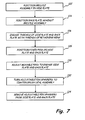
- FIG. 7 shows a diagram of a method of assembling brush seal assembly 100.
- Bristle assembly 12 is first positioned in recess 36 of side plate 14, Box 122.
- first surface 44 of back plate 102 is then positioned adjacent bristle assembly 12 such that bristle assembly 12 is sandwiched between side plate 14 and back plate 102.
- Outer threads 40 of side plate 14 and outer threads 108 of back plate 102 are then engaged with mating threads 120 of retaining ring 104 to thread side plate 14, bristle assembly 12, and back plate 102 within retaining ring 104, Box 126.
- Fixed pins 66a and 66b are positioned within first spanner holes 38a and 54a of side plate 14 and back plate 102, respectively, Box 128.
- movable pins 68a and 68b are then optionally adjusted within adjustment slots 62a and 62b until they are aligned to engage second spanner holes 38b and 54b of side plate 14 and back plate 102, respectively.
- Adjustable pin spanners 18a and 18b are then turned while retaining ring 104 is maintained in position, tightening side plate 14 and back plate 102 within retaining ring, Box 132. Once brush seal assembly 100 is threaded together, adjustable pin spanners 18a and 18b may be removed from side plate 14 and back plate 102, Box 134.
- the brush seal assembly disclosed herein provides a convenient, inexpensive, no-weld method of sandwiching a bristle assembly between a side plate and a back plate to form the brush seal assembly. By eliminating the welding step and subsequent stress-relieving heat treatment of the full brush seal assembly, the manufacturing time and cost of the brush seal assembly is significantly reduced.
- the brush seal assembly uses threading and adjustable pin spanners to easily assemble and disassemble the brush seal assembly.
- the simple disassembly and reassembly of the brush seal assembly also allows for easy replacement of individual components.
- the bristle assembly may be easily replaced with various wire materials and wire diameters.
- the side plate and back plate may also be replaced with various materials and machined critical inner diameters.
- various brush seal assembly combinations may be used that cannot be joined through conventional welding processes.
- the materials may include, but are not limited to: non-compatible metals, plastic-metal combinations, or high temperature carbon-based materials.
- the brush seal assembly may be used in any application where a seal is desired, including, but not limited to, a gas turbine engine.
Landscapes
- Engineering & Computer Science (AREA)
- General Engineering & Computer Science (AREA)
- Mechanical Engineering (AREA)
- Sealing Devices (AREA)
- Brushes (AREA)
- Turbine Rotor Nozzle Sealing (AREA)
Abstract
Description
- The present invention generally relates to brush seals. In particular, the present invention relates to a brush seal assembly utilizing threaded members.
- Brush seals are commonly used in gas turbine engines and other assemblies to restrict the escape of fluid (i.e. air) through a gap between a stationary part and a rotating part. For example, the stationary part may be a diffuser case and the rotating part may be a turbine shaft. Brush seals may also be used to seal gaps between two stationary parts or two rotating parts of a gas turbine engine. In either case, minimization of leakage is important in maintaining the efficiency of the system and to reduce fuel consumption.
- A brush seal generally includes packs of wire bristles that are sandwiched between two plates. It is common practice to weld the bristles and plates together. The brush seal must then undergo heat treatment after welding to relieve any residual stresses. Heat treatment typically involves securing the brush seal within a fixture and placing the fixture in an oven. The heat treatment is a time consuming and expensive process.
- While effective, the bristles of the brush seal eventually wear and need to be replaced over time. For example, replacement may be scheduled after a given number of hours or cycles of operation. However, because conventional brush seals are welded assemblies, removal of the brush seal can be difficult. In addition, because the individual components of the brush seal are welded together, individual components such as wire bristles cannot easily be replaced. Thus, replacement of the entire brush seal must occur at significant costs in regards to material labor and down time, even though only one of the subassemblies needs replacement.
- A current method used that allows replacement of individual components of the brush seal is to manufacture the brush seals in subassemblies without plate welding. These brush seals combine the bristles together and sandwich the bristle packs between the plates using clips or fasteners. While these methods are effective, they also require additional machining under relatively close tolerances, thus increasing the overall cost of production.
- A brush seal assembly according to one aspect of the invention includes a plurality of bristles, a joint, and a retaining assembly. Each of the bristles has a first end and a second end. The joint has a first side and a second side and connects the first ends of the bristles. The retaining assembly sandwiches the joint and includes a side plate, a back plate, and a threaded connection. The side plate engages the first side of the joint and the back plate engages the second side of the joint. The threaded connection holds the side plate and the back plate in engagement with the joint.
-
-
FIG. 1 is a perspective, partial cross-sectional view of a representative brush seal assembly. -
FIG. 2 is a cross-sectional view of a first embodiment of a brush seal assembly. -
FIG. 3 is an exploded side view of the first embodiment of the brush seal assembly. -
FIG. 4A is a partially exploded side view of the first embodiment of the brush seal assembly having a first bristle assembly. -
FIG. 4B is a partially exploded side view of the first embodiment of the brush seal assembly having axial slots. -
FIG. 4C is a partially exploded side view of the first embodiment of the brush seal assembly having a second bristle assembly. -
FIG. 5 is a diagram of a method of assembling the first embodiment of the brush seal assembly. -
FIG. 6 is a cross-sectional view of a second embodiment of a brush seal assembly. -
FIG. 7 is a diagram of a method of assembling the second embodiment of the brush seal assembly. -
FIG. 1 shows a perspective, cross-sectional view of a representativebrush seal assembly 10.Brush seal assembly 10 generally includesbristle assembly 12,side plate 14, andback plate 16.Adjustable pin spanners FIG. 3 )tighten side plate 14 toback plate 16,sandwiching bristle assembly 12 therebetween.Bristle assembly 12 has afirst side 19 and asecond side 20 and is formed of a plurality of densely arrangedwire bristles 21. Althoughbristle assembly 12 is depicted inFIG. 1 as having a full ring shape,bristle assembly 12 may have other shapes without departing from the intended scope of the present invention. For example,bristle assembly 12 may have an arcuate, segmented arcuate or linear shape. - Each of
wire bristles 21 has afirst end 22 and asecond end 24.First ends 22 ofwire bristles 21 reside at an outer diameter ofbristle assembly 12 and are secured together byjoint 25, such as a weld, and are generally connected tojoint 25 such thatwire bristles 21 are angled to a radial line.Joint 25 has afirst side 26 in line withfirst side 19 ofbristle assembly 12 and asecond side 27 in line withsecond side 20 ofbristle assembly 12.Second ends 24 ofwire bristles 21 extend away fromjoint 25 and reside at an inner diameter ofbristle assembly 12.Wire bristles 21 are made of a strong, flexible material. For example,wire bristles 21 may be made of an approximately 0.002 inch (0.05 mm) diameter to an approximately 0.006 inch (0.15 mm) diameter cobalt alloy wire. In an exemplary embodiment, first ends ofwire bristles 20 are connected tojoint 25 such that they are angled at approximately 45 degrees from a radial line. -
FIGS. 2 and3 show a cross-sectional view and an exploded view, respectively, of a first embodiment ofbrush seal assembly 10a, and will be discussed in conjunction with one another.Bristle assembly 12 is positioned betweenside plate 14 andback plate 16, all of which are removably connected to one another.Pin spanners side plate 14 andback plate 16 together.Side plate 14 provides a front cover to protectbristle assembly 12 and includesfirst surface 28,second surface 30,inner diameter 32,outer diameter 34,recess 36,first spanner hole 38a, andsecond spanner hole 38b (FIG. 3 ).Outer diameter 34 ofside plate 14 includesouter threads 40.Recess 36 is located withinsecond surface 30 ofside plate 14 and is sized to acceptfirst side 26 of joint 25 ofbristle assembly 12. Whenbrush seal assembly 10 is assembled,first side 20 ofbristle assembly 12 is positioned immediately adjacentsecond surface 30 ofside plate 14. A windage cover 42 (shown inFIG. 2 ) may also be integral toside plate 14 atinner diameter 32 ofside plate 14. Althoughside plate 14 is discussed as having twospanner holes side plate 14 may have any number of spanner holes around the circumference ofside plate 14. In addition, althoughouter diameter 34 is discussed as includingthreads 40, any locking feature known in the art may be used. -
Back plate 16 is the primary structural element ofbrush seal assembly 10a and provides downstream support tobrush seal assembly 10a by supportingbristle assembly 12 and preventing bristle blowover due to fluid pressure differential. Backplate 16 includesfirst surface 44,second surface 46,inner diameter 48,outer diameter 50,back cover 52,first spanner hole 54a,second spanner hole 54b, firstaxial slot 56a, and secondaxial slot 56b.Inner diameter 48 ofback plate 16 includesinner threads 58 that are engagable withouter threads 40 ofside plate 14. Stress calculations may be performed onthreads side plate 14 and backplate 16, respectively, to determine the optimum thread size and pitch relative to the size ofbrush seal assembly 10a and the resistive and compressive axial spring rate ofbristle assembly 12. Spanner holes 54a and 54b are formed inback cover 52, which extends acrosssecond surface 46 ofback plate 16. Back cover 52 also has ahole 59 in the center ofback cover 52 to position a component, such as a shaft or rotor, with clearance. Although backplate 16 is discussed as having twospanner holes axial slots plate 16 may have any number of spanner holes and axial slots around the circumference ofback plate 16. Also, as withside plate 14, althoughinner diameter 48 is discussed as includingthreads 58, any locking feature known in the art may be used. -
Bristle assembly 12,side plate 14, and backplate 16 are assembled together with the use of adjustablepin spanner tools Adjustable pin spanners adjustable pin spanner 18a generally includesspanner arm 60a,adjustment slot 62a, fixedpin 64a,movable pin 66a, and threadedfastener 68a. Secondadjustable pin spanner 18b functions and interacts similarly to firstadjustable pin spanner 18a and generally includesspanner arm 60b,adjustment slot 62b, fixedpin 64b,movable pin 66b, and threadedfastener 68b.Adjustable pin spanners - To assemble
brush seal assembly 10a, joint 25 and bristleassembly 12 are positioned againstsecond surface 30 ofside plate 14 withfirst side 26 of joint 25 engaging recess 36 (shown inFIG. 2 ) ofside plate 14. As can be seen inFIG. 3 ,outer threads 40 ofside plate 14 are engageable withinner threads 58 ofback plate 16, allowingside plate 14 and bristleassembly 12 to fit withininner diameter 48 ofback plate 16. Once in place,threads 40 ofside plate 14 are threaded intothreads 58 of back plate 16 (shown inFIGS. 2 and3 ).Side plate 14 and bristleassembly 12 are threaded withininner diameter 48 ofback plate 16 untilsecond side 27 of joint 25 andsecond side 21 ofbristle assembly 12 abutsback cover 52 ofback plate 16. Second ends 24 of wire bristles 21 extend pastinner diameters side plate 14 and backplate 16, respectively, allowing bristleassembly 12 to reach a component, such as a rotor, to form a seal. - Although not shown in
FIGS. 2 and3 ,brush seal assembly 10a may optionally include a washer positioned betweensecond surface 30 ofside plate 14 andfirst side 19 ofbristle assembly 12, as well as positioned betweensecond side 20 ofbristle assembly 12 andfirst surface 44 ofback plate 16. The washers would function to protect wire bristles 21 asside plate 14 and backplate 16 spin againstbristle assembly 12 during assembly. -
FIGS. 4A-4C show how first and secondadjustable pin spanners FIG. 4A showsadjustable pin spanners spanner holes brush seal assembly 10a.FIG. 4B showsadjustable pin spanners spanner slots 38a and 38 andaxial slots brush seal assembly 10b.FIG. 4C showsadjustable pin spanners brush seal assembly 10c having a smaller diameter thanbrush seal assemblies -
FIG. 4A shows a side view ofbrush seal assembly 10a. Afterside plate 14 and bristleassembly 12 are positioned withinback plate 16, firstadjustable pin spanner 18a is positioned immediately adjacentfirst surface 28 ofside plate 14.Fixed pin 64a of firstadjustable pin spanner 18a is aligned with, and engages,first spanner hole 38a ofside plate 14.Movable pin 66a is then adjusted withinadjustment slot 62a until aligned withsecond spanner hole 38b ofside plate 14.Movable pin 66a is then positioned withinsecond spanner hole 38b and is maintained in place withinadjustment slot 62a by threadedfastener 68a. Similarly,spanner arm 60b ofadjustable pin spanner 18b is positioned immediately adjacentsecond surface 46 ofback plate 16 and engages backplate 16 in the same manner that firstadjustable pin spanner 18a engagesside plate 14. - In this position,
adjustable pin spanners assembly 12 betweenside plate 14 and backplate 16, which formbrush seal assembly 10a. After first and secondadjustable pin spanners side plate 14 and backplate 16, respectively,adjustable pin spanners FIG. 4A ) to tightenside plate 14, bristleassembly 12, and backplate 16 together. Asadjustable pin spanners side plate 14 is turned in the same direction as firstadjustable pin spanner 18a and backplate 16 is turned in the same direction as secondadjustable pin spanner 18b. Becauseside plate 14 and backplate 16 are turning in opposing directions,side plate 14 and backplate 16 are further threaded together byouter threads 40 ofside plate 14 engaginginner threads 58 ofback plate 16. Afterbrush seal assembly 10a is threaded together,adjustable pin spanners side plate 14 and backplate 16. - As previously mentioned,
side plate 14 and backplate 16 may each have more than two spanner holes. The additional spanner holes provide leverage for a user turningadjustable pin spanners side plate 14 and backplate 16 if clearance is limited. Depending on the position of the spanner holes relative to the assembler, it may be advantageous for the assembler to removepins adjustable pin spanners side plate 14 and backplate 16 together. Thus, the assembler is able to placeadjustable pin spanners side plate 14 and backplate 16 as necessary to obtain optimal handling ofbrush seal assembly 10a. -
FIG. 4B shows a side view ofbrush seal assembly 10b which generally includes aback plate 70, bristleassembly 12, andside plate 14. While firstadjustable pin spanner 18a interacts withside plate 14 in the manner described forbrush seal assembly 10a, fixedpin 64b andmovable pin 66b of secondadjustable pin spanner 18b engageaxial slots back plate 70. Once fixedpin 64b is positioned within firstaxial slot 56a,movable pin 66b is adjusted withinadjustment slot 62b and aligned with secondaxial slot 56b. Once fixedpin 64b andmovable pin 66b are properly positioned withinaxial slots brush seal assembly 10b is tightened in a similar manner asbrush seal assembly 10a.Axial slots brush seal assembly 10b ifback cover 52 ofback plate 70 does not includespanner holes back plate 70 optionally does not include a back cover, or if it is more convenient to useaxial slots - Similar to brush
seal assembly 10a,side plate 14 may have more than two spanner holes and backplate 16 may have more than two axial slots. The additional spanner holes and axial slots function in the same manner as the additional spanner holes inbrush seal assembly 10a, providing leverage for a user turningadjustable pin spanners -
FIG. 4C shows a side view ofbrush seal assembly 10c havingside plate 72, bristleassembly 74, and backplate 76. The components ofbrush seal assembly 10c interact and function similarly to the components ofbrush seal assembly 10a described in the discussion ofFIG. 4A , except that the outer diameters ofside plate 72, bristleassembly 74, and backplate 76 are smaller than the outer diameters ofside plate 14, bristleassembly 12, and back plate 16 (shown inFIG. 4A ). Because the diameters ofbrush seal assembly 10c are smaller than the diametersbrush seal assembly 10a,movable pins adjustable pin spanners Movable pins adjustment slots movable pin 66a is engagable withsecond spanner hole 38b ofside plate 72 and secondmovable pin 66b is engagable withsecond spanner hole 54b ofback plate 76. After fixedpins movable pins side plate 72 and backplate 76,brush seal assembly 10c is tightened by first and secondadjustable pin spanners brush seal assembly 10a. AlthoughFIG. 4C depicts a brush seal assembly having a smaller diameter thanbrush seal assembly 10a, brush seal assemblies of any diameter may be joined together usingadjustable pin spanners brush seal assembly 10c. -
FIG. 5 shows a diagram of a method of assemblingbrush seal assembly 10.Bristle assembly 12 is first positioned inrecess 36 ofside plate 14,Box 78.Threads 40 ofside plate 14 are then engaged withmating threads 58 ofback plate 16,Box 80. As depicted inBox 82, asside plate 14 and backplate 16 are threaded together,first surface 44 ofback plate 16 is positioned immediatelyadjacent bristle assembly 12 such that bristleassembly 12 is sandwiched betweenside plate 14 and backplate 16.Fixed pins first spanner hole 38a ofside plate 14 andfirst spanner hole 54a ofback plate 16, respectively,Box 84. As optionally shown in Box 86 (optional),movable pins adjustment slots side plate 14 and backplate 16, respectively. Note thatmovable pins Adjustable pin spanners side plate 14, bristleassembly 12, and backplate 16 together,Box 88. Afterbrush seal assembly 10 is threaded together,adjustable pin spanners side plate 14 and backplate 16, Box 90. -
FIG. 6 shows a cross-sectional view ofbrush seal assembly 100 which generally includes bristleassembly 12,side plate 14, backplate 102, and retainingring 104.Brush seal assembly 100 functions similarly tobrush seal assembly 10a except thatbrush seal assembly 100 includes retainingring 104 and outer diameter 106 ofback plate 102 includes outer threads 108. Retainingring 104 is also threaded and connectsside plate 14 and backplate 102 together. Retainingring 104 hasfirst surface 110,second surface 112,inner diameter 114,outer diameter 116, firstaxial slot 118a, and second axial slot 118b (not shown inFIG. 6 , second axial slot 118b is positioned similarly to secondaxial slot 56b ofbrush seal assembly 10a shown inFIG. 3 ).Inner diameter 114 of retainingring 104 includesinner threads 120 for engagingouter threads 40 ofside plate 14 and outer threads 108 ofback plate 102. After joint 25 is positioned withinrecess 36 ofside plate 14,first surface 44 ofback plate 102 is positioned immediatelyadjacent bristle assembly 12.Outer threads 40 ofside plate 14 andouter threads 58 ofback plate 102 are then threaded toinner threads 120 of retainingring 104, creatingbrush seal assembly 100. - First
adjustable pin spanner 18a is then positioned againstfirst surface 28 ofside plate 14 and secondadjustable pin spanner 18b is positioned againstsecond surface 46 ofback plate 102.Fixed pins first spanner holes side plate 14 and backplate 102, respectively.Movable pins adjustment slots side plate 14 and backplate 102, respectively. Once fixedpins movable pins spanner holes side plate 14 and backplate 102,adjustable pin spanners side plate 14 and backplate 102 to retainingring 104. Asadjustable pin spanners side plate 14 and backplate 102, retainingring 104 is held stationary byaxial slots 118a and 118b. Asside plate 14 and backplate 102 are turned within retainingring 104,outer threads 40 ofside plate 14 and outer threads 108 ofback plate 102 are threaded tothreads 120 of retainingring 104. Although retainingring 104 is discussed as being held stationary byaxial slots 118a and 118b, retainingring 104 may be held stationary by any means known in the art, including, but not limited to: some other feature onouter diameter 116 of retainingring 104, by a fixture, or by a vise. -
FIG. 7 shows a diagram of a method of assemblingbrush seal assembly 100.Bristle assembly 12 is first positioned inrecess 36 ofside plate 14,Box 122. As depicted inBox 124,first surface 44 ofback plate 102 is then positioned adjacent bristleassembly 12 such that bristleassembly 12 is sandwiched betweenside plate 14 and backplate 102.Outer threads 40 ofside plate 14 and outer threads 108 ofback plate 102 are then engaged withmating threads 120 of retainingring 104 tothread side plate 14, bristleassembly 12, and backplate 102 within retainingring 104,Box 126.Fixed pins first spanner holes side plate 14 and backplate 102, respectively,Box 128. As shown inoptional Box 130,movable pins adjustment slots side plate 14 and backplate 102, respectively.Adjustable pin spanners ring 104 is maintained in position, tighteningside plate 14 and backplate 102 within retaining ring,Box 132. Oncebrush seal assembly 100 is threaded together,adjustable pin spanners side plate 14 and backplate 102,Box 134. - The brush seal assembly disclosed herein provides a convenient, inexpensive, no-weld method of sandwiching a bristle assembly between a side plate and a back plate to form the brush seal assembly. By eliminating the welding step and subsequent stress-relieving heat treatment of the full brush seal assembly, the manufacturing time and cost of the brush seal assembly is significantly reduced. The brush seal assembly uses threading and adjustable pin spanners to easily assemble and disassemble the brush seal assembly. In addition, the simple disassembly and reassembly of the brush seal assembly also allows for easy replacement of individual components. For example, the bristle assembly may be easily replaced with various wire materials and wire diameters. Similarly, the side plate and back plate may also be replaced with various materials and machined critical inner diameters. Lastly, various brush seal assembly combinations may be used that cannot be joined through conventional welding processes. The materials may include, but are not limited to: non-compatible metals, plastic-metal combinations, or high temperature carbon-based materials. The brush seal assembly may be used in any application where a seal is desired, including, but not limited to, a gas turbine engine.
- Although the present invention has been described with reference to preferred embodiments, workers skilled in the art will recognize that changes may be made in form and detail without departing from the scope of the invention.
Claims (16)
- A brush seal assembly (10; 100) comprising:a plurality of bristles (21), each of the bristles (21) having a first end (22) and a second end (24);a joint (25) for connecting the first ends (22) of the bristles (21), the joint (25) having a first side (26) and a second side (27); anda retaining assembly for sandwiching the joint (25), the retaining assembly including a side plate (14) for engaging the first side (26) of the joint (25), a back plate (16; 102) for engaging the second side (27) of the joint (25), and a threaded connection for holding the side plate (14) and the back plate (16; 102) in engagement with the joint (25).
- A brush seal assembly (10; 100) comprising:a bristle assembly (12) having a first side (19) and a second side (20); anda retaining assembly including a threaded connection, a first retaining plate (14) positioned adjacent the first side (19) of the bristle assembly (12), and a second retaining plate (16; 102) positioned adjacent the second side (20) of the bristle assembly (12).
- The brush seal assembly of claim 1 or 2, wherein the first retaining plate (14) or side plate (14) has outer threads (40) and the second retaining plate (16) or back plate (16) has inner threads (58) engagable with the outer threads (40) of the first retaining plate (14) or side plate (14) to form the threaded connection.
- The brush seal assembly of claim 1 or 2, wherein the first retaining plate (14) or side plate (14) has outer threads (40) and the second retaining plate (102) or back plate (102) has outer threads (108).
- The brush seal assembly of claim 4, wherein the retaining assembly further comprises a retaining ring (104) having inner threads (120) engagable with the outer threads (40) of the first retaining plate (14) or side plate (14) and the outer threads (108) of the second retaining plate (102) or back plate (102) to form the threaded connection.
- The brush seal assembly of any of claims 1, 2 or 3, wherein the first retaining plate (14) or side plate (14) is positioned within the second retaining plate (16) or back plate (16).
- The brush seal assembly of any preceding claim, wherein the first retaining plate (14) or side plate (14) has a first spanner hole (38a) and a second spanner hole (38b) engageable with a first adjustable pin spanner (60a) and the second retaining plate (16; 102) or back plate (16; 102) has a first spanner hole (54a) and a second spanner hole (54b) engageable with a second adjustable pin spanner (60b).
- The brush seal assembly of any preceding claim, wherein the first retaining plate (14) or side plate (14) has a first spanner hole (38a) and a second spanner hole (38b) engageable with a first adjustable pin spanner (60a) and the second retaining plate (16; 102) or back plate (16; 102) has a first axial slot (56a) and a second axial slot (56b) engageable with a second adjustable pin spanner (60b).
- A method for assembling a brush seal assembly (10; 100) comprising:positioning a bristle assembly (12) between a first plate (14) and a second plate (16; 102) of a retaining assembly;engaging threads (40) of the first plate (14) with first mating threads (58; 120) of the retaining assembly;engaging threads (58; 108) of the second plate (16; 102) with second mating threads (40; 120) of the retaining assembly; andsecuring the first plate (14) to the second plate (16; 102).
- The method of claim 9, wherein engaging the threads (40) of the first plate (14) with first mating threads comprises engaging the threads (40) of the first plate (14) with the threads (58) of the second plate (16).
- The method of claim 9 or 10, wherein engaging the threads (58) of the second plate (16) with second mating threads comprises engaging the threads (58) of the second plate (16) with the threads (40) of the first plate (14).
- The method of claim 9, wherein engaging the threads of the first plate (14) with first mating threads and engaging the threads of the second plate (16) with second mating threads comprises engaging the threads (40) of the first plate (14) and the threads (108) of the second plate (102) with threads (120) of a retaining ring (104).
- The method of any of claims 9 to 12, wherein securing the first plate (14) to the second plate (16; 102) comprises using at least one adjustable pin spanner (60a).
- The method of claim 13, wherein securing the first plate (14) to the second plate (16; 102) further comprises using a second adjustable pin spanner (60b).
- The method of claim 14, wherein securing the first plate (14) to the second plate (16; 102) comprises engaging pins (64a, 66a) of the first adjustable pin spanner (60a) with holes (38a, 38b) of the first plate (14) and engaging pins (64b, 66b) of the second adjustable pin spanner (60b) with holes (54a, 54b) of the second plate (16; 102).
- The method of claim 15, wherein securing the first plate (14) to the second plate (16; 102) comprises turning the first adjustable pin spanner (60a) and the second adjustable pin spanner (60b) in opposing directions.
Applications Claiming Priority (1)
| Application Number | Priority Date | Filing Date | Title |
|---|---|---|---|
| US11/636,311 US20080136112A1 (en) | 2006-12-08 | 2006-12-08 | Brush seal assemblies utilizing a threaded fastening method |
Publications (1)
| Publication Number | Publication Date |
|---|---|
| EP1930634A1 true EP1930634A1 (en) | 2008-06-11 |
Family
ID=39159356
Family Applications (1)
| Application Number | Title | Priority Date | Filing Date |
|---|---|---|---|
| EP07254738A Withdrawn EP1930634A1 (en) | 2006-12-08 | 2007-12-07 | Brush seal assemblies utilizing a threaded fastening method |
Country Status (2)
| Country | Link |
|---|---|
| US (1) | US20080136112A1 (en) |
| EP (1) | EP1930634A1 (en) |
Cited By (3)
| Publication number | Priority date | Publication date | Assignee | Title |
|---|---|---|---|---|
| EP2080938A1 (en) * | 2008-01-15 | 2009-07-22 | United Technologies Corporation | Brush seal assembly and method of manufacturing same |
| FR2997470A1 (en) * | 2012-10-30 | 2014-05-02 | Snecma | Holding device for holding brush seal of lubrication enclosure of turbojet engine, has cylindrical part formed by cylindrical face and thread that is engaged with another thread to ensure axial translation of lock with respect to cover |
| EP2885507A4 (en) * | 2012-08-14 | 2015-10-07 | United Technologies Corp | INNER AIR SEAL WITH COMPLETELY THREADED RING |
Families Citing this family (13)
| Publication number | Priority date | Publication date | Assignee | Title |
|---|---|---|---|---|
| US7744092B2 (en) * | 2007-04-30 | 2010-06-29 | General Electric Company | Methods and apparatus to facilitate sealing in rotary machines |
| GB2461506B (en) * | 2008-06-30 | 2010-08-25 | Rolls Royce Plc | A seal arrangement |
| US8740225B2 (en) * | 2009-06-03 | 2014-06-03 | Exponential Technologies, Inc. | Hydrodynamic bore seal |
| US10125872B2 (en) | 2011-08-18 | 2018-11-13 | Bal Seal Engineering, Inc. | Reciprocating seal for high pulsating pressure |
| GB201202104D0 (en) * | 2012-02-08 | 2012-03-21 | Rolls Royce Plc | Leaf seal |
| DE202012013191U1 (en) * | 2012-05-03 | 2015-07-14 | En3 Gmbh | Shaft seal with fins |
| US10801622B2 (en) * | 2013-04-18 | 2020-10-13 | Bal Seal Engineering, Llc | Interlocking face seal assemblies and related methods |
| CN105290754A (en) * | 2015-11-06 | 2016-02-03 | 苏州汉腾自动化设备有限公司 | Device for mounting carbon brush onto polishing machine |
| CN105436858B (en) * | 2015-11-06 | 2019-01-25 | 苏州汉腾自动化设备有限公司 | A brush holder installation device |
| US10563771B2 (en) * | 2016-04-07 | 2020-02-18 | United Technologies Corporation | Wire mesh brush seal windage cover |
| JP2021507163A (en) | 2017-12-13 | 2021-02-22 | エクスポネンシャル テクノロジーズ, インコーポレイテッドExponential Technologies, Inc. | Rotary fluid flow device |
| US11168683B2 (en) | 2019-03-14 | 2021-11-09 | Exponential Technologies, Inc. | Pressure balancing system for a fluid pump |
| US11041397B1 (en) * | 2019-12-13 | 2021-06-22 | Raytheon Technologies Corporation | Non-metallic side plate seal assembly for a gas turbine engine |
Citations (4)
| Publication number | Priority date | Publication date | Assignee | Title |
|---|---|---|---|---|
| FR2731490A1 (en) * | 1995-03-08 | 1996-09-13 | Snecma | Process of fabrication brush joint for use with rotating shafts |
| WO2001013013A1 (en) * | 1999-08-11 | 2001-02-22 | Mtu Aero Engines Gmbh | Brush sealing ring |
| EP1347218A2 (en) * | 2002-03-20 | 2003-09-24 | United Technologies Corporation | Brush seal |
| US20050151323A1 (en) * | 2004-01-09 | 2005-07-14 | United Technologies Corporation | Quick build brush seals |
Family Cites Families (22)
| Publication number | Priority date | Publication date | Assignee | Title |
|---|---|---|---|---|
| US2334349A (en) * | 1941-10-29 | 1943-11-16 | Victor Mfg & Gasket Co | Oil seal construction |
| GB8712681D0 (en) * | 1987-05-29 | 1987-07-01 | Cross Mfg Co 1938 Ltd | Brush seals |
| DE3802653C2 (en) * | 1988-01-29 | 2000-06-29 | Mtu Muenchen Gmbh | Brush seal |
| US5066025A (en) * | 1990-06-18 | 1991-11-19 | Hanrahan Paul R | Brush seal assembly |
| DE4027520A1 (en) * | 1990-08-31 | 1992-03-12 | Festo Kg | RING-SHAPED SEALING ARRANGEMENT AND VALVE EQUIPPED WITH IT |
| US5425543A (en) * | 1993-09-17 | 1995-06-20 | Buckshaw; Dennis J. | Seal assembly for rotating shaft |
| US5630590A (en) * | 1996-03-26 | 1997-05-20 | United Technologies Corporation | Method and apparatus for improving the airsealing effectiveness in a turbine engine |
| DE19720649C2 (en) * | 1997-05-16 | 2000-09-28 | Mtu Muenchen Gmbh | Brush seal |
| US6318728B1 (en) * | 1997-07-11 | 2001-11-20 | Demag Delaval Turbomachinery Corporation | Brush-seal designs for elastic fluid turbines |
| EP0905421B1 (en) * | 1997-09-25 | 2003-10-22 | ALSTOM (Switzerland) Ltd | Brush seal |
| US6808179B1 (en) * | 1998-07-31 | 2004-10-26 | Concepts Eti, Inc. | Turbomachinery seal |
| US6168162B1 (en) * | 1998-08-05 | 2001-01-02 | General Electric Co. | Self-centering brush seal |
| GB2344393B (en) * | 1998-10-15 | 2003-07-09 | Luk Lamellen & Kupplungsbau | Hydraulic release system |
| GB9929587D0 (en) * | 1999-12-16 | 2000-02-09 | Rolls Royce Plc | A seal arrangement |
| JP2002267023A (en) * | 2001-03-13 | 2002-09-18 | Eagle Engineering Aerospace Co Ltd | Brush seal device |
| US6402157B1 (en) * | 2001-08-20 | 2002-06-11 | General Electric Company | Brush seal and method of using brush seal |
| US20030160392A1 (en) * | 2002-02-12 | 2003-08-28 | Szymbor John A. | Bristle arrangement for brush seal, method and assembly for making same, and method of making brush seal |
| US20030201608A1 (en) * | 2002-04-25 | 2003-10-30 | United Technologies Corporation | Brush seal with fewer parts |
| US8181965B2 (en) * | 2002-06-27 | 2012-05-22 | United Technologies Corporation | Replaceable brush seal elements |
| US7334311B2 (en) * | 2004-11-03 | 2008-02-26 | United Technologies Corporation | Method of forming a nested can brush seal |
| US7226054B2 (en) * | 2004-12-14 | 2007-06-05 | United Technologies Corporation | Clamp lock brush seal assembly |
| US20070040335A1 (en) * | 2005-08-22 | 2007-02-22 | General Electric Company | Axially adjustable sealing ring |
-
2006
- 2006-12-08 US US11/636,311 patent/US20080136112A1/en not_active Abandoned
-
2007
- 2007-12-07 EP EP07254738A patent/EP1930634A1/en not_active Withdrawn
Patent Citations (4)
| Publication number | Priority date | Publication date | Assignee | Title |
|---|---|---|---|---|
| FR2731490A1 (en) * | 1995-03-08 | 1996-09-13 | Snecma | Process of fabrication brush joint for use with rotating shafts |
| WO2001013013A1 (en) * | 1999-08-11 | 2001-02-22 | Mtu Aero Engines Gmbh | Brush sealing ring |
| EP1347218A2 (en) * | 2002-03-20 | 2003-09-24 | United Technologies Corporation | Brush seal |
| US20050151323A1 (en) * | 2004-01-09 | 2005-07-14 | United Technologies Corporation | Quick build brush seals |
Cited By (4)
| Publication number | Priority date | Publication date | Assignee | Title |
|---|---|---|---|---|
| EP2080938A1 (en) * | 2008-01-15 | 2009-07-22 | United Technologies Corporation | Brush seal assembly and method of manufacturing same |
| US8727354B2 (en) | 2008-01-15 | 2014-05-20 | United Technologies Corporation | Brush seal assembly and method of manufacturing same |
| EP2885507A4 (en) * | 2012-08-14 | 2015-10-07 | United Technologies Corp | INNER AIR SEAL WITH COMPLETELY THREADED RING |
| FR2997470A1 (en) * | 2012-10-30 | 2014-05-02 | Snecma | Holding device for holding brush seal of lubrication enclosure of turbojet engine, has cylindrical part formed by cylindrical face and thread that is engaged with another thread to ensure axial translation of lock with respect to cover |
Also Published As
| Publication number | Publication date |
|---|---|
| US20080136112A1 (en) | 2008-06-12 |
Similar Documents
| Publication | Publication Date | Title |
|---|---|---|
| EP1930634A1 (en) | Brush seal assemblies utilizing a threaded fastening method | |
| EP1672256B1 (en) | Clamp lock and brush seal assembly | |
| US7931276B2 (en) | Brush seal | |
| US20080029968A1 (en) | Nested can brush seal | |
| CA2715591C (en) | Gas turbine engine thermal expansion joint | |
| JP2002267023A (en) | Brush seal device | |
| JP2020037997A (en) | Grommets for turbine engines | |
| JP6644444B2 (en) | Split type brush seal device and assembling method thereof | |
| EP1706659B1 (en) | Quick build brush seals | |
| CN110695910A (en) | Tool and method for disassembling and assembling exhaust valve and valve seat of diesel engine | |
| CN107398676A (en) | Pipeline assembles centralising device and pipeline joint assembly method | |
| CN212859287U (en) | Clamping type wrench for dismounting circular nut with tooth groove in airplane pipeline | |
| JP2009115167A (en) | Clamp | |
| EP3746267B1 (en) | Bolt tightening system | |
| RU2247267C1 (en) | Device for locking threaded joints | |
| JPH11132051A (en) | Turbocharger | |
| CN112025595A (en) | Clamping type wrench for toothed-groove round nut in airplane pipeline | |
| EP4368344A1 (en) | Centering a washer to a fastener element during installation | |
| CN223227624U (en) | Assembly tooling for the steam inlet valve short pipe and high-pressure cylinder | |
| KR102658098B1 (en) | hose connection system | |
| FR3164749A1 (en) | RING FIXING DEVICE FOR AN AIRCRAFT TURBOMACHINE | |
| JP2001317659A (en) | Pipe mounting and dismounting device | |
| CN118905378A (en) | Axial diffuser welding tool and application method thereof | |
| WO2015157232A1 (en) | Exhaust system having segmented service flange |
Legal Events
| Date | Code | Title | Description |
|---|---|---|---|
| PUAI | Public reference made under article 153(3) epc to a published international application that has entered the european phase |
Free format text: ORIGINAL CODE: 0009012 |
|
| AK | Designated contracting states |
Kind code of ref document: A1 Designated state(s): AT BE BG CH CY CZ DE DK EE ES FI FR GB GR HU IE IS IT LI LT LU LV MC MT NL PL PT RO SE SI SK TR |
|
| AX | Request for extension of the european patent |
Extension state: AL BA HR MK RS |
|
| 17P | Request for examination filed |
Effective date: 20080915 |
|
| 17Q | First examination report despatched |
Effective date: 20081009 |
|
| AKX | Designation fees paid |
Designated state(s): GB |
|
| REG | Reference to a national code |
Ref country code: DE Ref legal event code: 8566 |
|
| STAA | Information on the status of an ep patent application or granted ep patent |
Free format text: STATUS: THE APPLICATION IS DEEMED TO BE WITHDRAWN |
|
| 18D | Application deemed to be withdrawn |
Effective date: 20090220 |