US7931276B2 - Brush seal - Google Patents
Brush seal Download PDFInfo
- Publication number
- US7931276B2 US7931276B2 US10/104,337 US10433702A US7931276B2 US 7931276 B2 US7931276 B2 US 7931276B2 US 10433702 A US10433702 A US 10433702A US 7931276 B2 US7931276 B2 US 7931276B2
- Authority
- US
- United States
- Prior art keywords
- plates
- brush seal
- bristles
- recited
- bristle arrangement
- Prior art date
- Legal status (The legal status is an assumption and is not a legal conclusion. Google has not performed a legal analysis and makes no representation as to the accuracy of the status listed.)
- Active, expires
Links
Images


Classifications
-
- F—MECHANICAL ENGINEERING; LIGHTING; HEATING; WEAPONS; BLASTING
- F16—ENGINEERING ELEMENTS AND UNITS; GENERAL MEASURES FOR PRODUCING AND MAINTAINING EFFECTIVE FUNCTIONING OF MACHINES OR INSTALLATIONS; THERMAL INSULATION IN GENERAL
- F16J—PISTONS; CYLINDERS; SEALINGS
- F16J15/00—Sealings
- F16J15/16—Sealings between relatively-moving surfaces
- F16J15/32—Sealings between relatively-moving surfaces with elastic sealings, e.g. O-rings
- F16J15/3284—Sealings between relatively-moving surfaces with elastic sealings, e.g. O-rings characterised by their structure; Selection of materials
- F16J15/3288—Filamentary structures, e.g. brush seals
Definitions
- This invention relates to brush seals. Specifically, this invention relates to the various components that form the brush seal.
- Brush seals are commonly used on gas turbine engines.
- the brush seals typically prevent secondary flow in the engine from escaping through a gap between a stationary part (e.g. a diffuser case) and a rotating part (e.g. a turbine shaft).
- Brush seals can have other uses, such as sealing a gap between stationary parts of the engine.
- a brush seal typically includes packs of wire bristles sandwiched between plates.
- the bristle packs and plates are typically welded together to form the brush seal.
- the brush seal must undergo heat treatment after the welding step to relieve any residual stresses. Heat treatment typically involves securing the brush seal within a fixture, then placing the fixture in an oven. The heat treatment process is time consuming and can be expensive.
- the welding step transforms the discrete sub-assemblies of the brush seal into one piece.
- the one-piece arrangement prevents the removal of a sub-assembly without affecting or damaging the remainder of the brush seal. This means a mechanic must replace the entire brush seal during maintenance. Replacement of the entire brush seal must occur despite the fact that only one of the sub-assemblies (typically the bristle packs) needs replacement.
- the bristle packs of the brush seal are expensive. The main factor influencing cost is the amount of raw material used. Each individual bristle in the bristle pack is a taken from a length of wire. A commonly used wire is a 0.002′′, 0.003′′, 0.004 or 0.006′′ diameter cobalt alloy wire.
- One type of bristle pack can have approximately 5000 bristles per linear inch. This type of bristle pack clearly contains a large amount of wire. When used in a 12′′ outer diameter single stage brush seal, this type of bristle pack can contain approximately 2.6 miles of wire.
- the brush seal comprises: a bristle arrangement, including a plurality of bristles and a joint securing the bristles together; plates flanking the bristle arrangement; and a feature on the plates to receive the joint.
- the brush seals comprises: a plurality of bristles, each having a first end and an opposed second end; and plates receiving the bristles therebetween, each having a first end and a second end.
- the first ends of the bristles extend past said first ends of said plates and the second ends of the bristles reside between the first and second ends of the plates.
- the method comprises the steps of: providing a brush seal having a bristle arrangement secured between plates; removing the bristle arrangement from the plates; providing a replacement bristle arrangement; and placing said replacement bristle arrangement between the plates.
- FIG. 1 is a perspective view of a section of a conventional brush seal
- FIG. 2 a is a cross-sectional view a brush seal of the present invention
- FIG. 2 b is a perspective view of a section of the brush seal in FIG. 2 a;
- FIG. 3 a is a perspective view of a section of another brush seal of the present invention.
- FIG. 3 b is a perspective view of an alternate arrangement of the brush seal in FIG. 3 a;
- FIG. 4 is a perspective view of a section of another brush seal of the present invention.
- FIG. 5 is a perspective view of a section of another brush seal of the present invention.
- FIG. 6 is a perspective view of a section of another brush seal of the present invention.
- FIG. 7 is a perspective view of a section of another brush seal of the present invention.
- FIG. 1 displays a conventional annular brush seal 100 .
- the brush seal 100 includes several sub-assemblies, namely a back plate 101 , side plate 103 and a bristle pack 105 .
- the metal plates 101 , 103 flank the bristle pack 105 .
- the bristle pack 105 comprises a plurality of densely arranged wire bristles. Each of the bristles has a first end 107 and an opposed second end 109 . While extending at an angle to a radial line, the first ends 107 of the bristles reside at the inner diameter of the brush seal 100 . The second ends 109 of the bristles reside at the outer diameter of the brush seal 100 .
- the plates 101 , 103 and the bristle pack 105 are welded together to form the brush seal 100 . Specifically, the outer diameter of the plates 101 , 103 and the bristle pack 105 are welded together to sandwich the bristles between the plates 101 , 103 .
- FIGS. 2 a and 2 b display one alternative embodiment of a brush seal 200 of the present invention. Similar to the conventional brush seal 100 , the brush seal 200 includes a back plate 201 and a side plate 203 .
- the brush seal 200 uses a pre-assembled bristle assembly.
- the brush seal 200 has plates 201 , 203 removably secured to each other.
- the brush seal 200 includes a bristle arrangement 205 .
- the bristle arrangement 205 includes a plurality of bristles 207 secured together by a joint 209 .
- the bristles 207 could be made from the same cobalt alloy wire as the bristles in the conventional brush seal 100 .
- the bristle arrangement 205 described herein is annular, one could refer to the bristle arrangement 205 as a bristle ring.
- the bristle arrangement 205 could, however, have other shapes.
- the bristle arrangement 205 could have an arcuate (not shown) or a linear shape (not shown).
- the joint 209 extends continuously along the outer diameter of the bristle arrangement 205 .
- the joint 209 is a weld joint.
- U.S. patent application Ser. No. 10/074,191 describes in more detail the method of making the bristle arrangement 205 .
- the present invention could use other methods to produce the joint 209 .
- the joint 209 retains the bristles 207 in the bristle arrangement 205 .
- the joint 209 obviates the need to weld the bristles 207 to the plates 201 , 203 .
- the brush seal 200 retains the bristle arrangement 205 using grooves 211 , 213 in the inner faces 215 , 217 of the plates 201 , 203 .
- the grooves 211 , 213 define a cavity 219 which receives the joint 209 of the bristle arrangement 205 .
- the joint 209 preferably does not interference fit within the cavity 219 , the cavity 219 should prevent radial movement of the bristle arrangement 205 during engine operation.
- the inner faces 215 , 217 also form a gap 221 in communication with the cavity 219 .
- the gap 221 is sufficiently large to allow the bristles 207 to extend past the plates 201 , 203 .
- the gap 221 is sufficiently small to compress the bristles 207 and to prevent movement of the bristle arrangement 205 during engine operation.
- the inner faces 215 , 217 of the plates 201 , 203 at the gap 221 could have features thereon to improve retention of the bristle arrangement 205 .
- Knurls are an example of such features.
- the use of the bristle arrangement 205 highlights one benefit of the present invention.
- the brush seal 200 can use shorter bristles 207 than the conventional brush seal 100 .
- the conventional brush seal 100 must weld the bristles 107 to the plates 101 , 103 . Since the weld is located at the outer diameter of the brush seal 100 , the bristles 100 must extend to the outer diameter.
- the brush seal 200 does not weld of the bristles 207 to the plates 201 , 203 . Therefore, the bristles 207 need not extend to the outer diameter of the brush seal 200 . As seen in FIG. 2 b , the outermost extent of the bristle arrangement 205 is at a position medial to the inner diameter and the outer diameter of the brush seal 200 .
- the present invention can reduce the length of the bristles 207 up to approximately 20%. Using the example above, reducing the length of the bristles in a 12′′ outer diameter single stage brush seal by 20% can save approximately 0.5 miles of wire.
- the brush seal 200 uses a retainer to secure the plates 201 , 203 together.
- the brush seal 200 uses a clip 223 to secure the plates 201 , 203 together.
- the clip 223 can have a C-shape with extensions 225 , 227 that engage corresponding grooves 229 , 231 in the plates 201 , 203 .
- an operator could place the back plate 201 in a fixture (not shown). The operator would then place the joint 209 of the bristle arrangement 205 in the groove 213 . The operator would then place the side plate 203 over the bristle arrangement 205 (ensuring the joint 209 enters the groove 211 ). The operator would then tighten the fixture to sandwich bristle arrangement 205 between the plates 201 , 203 .
- the operator secures the retaining clip 223 to the plates 201 , 203 with conventional techniques. For example, the operator could set one extension 225 in the corresponding groove 229 . The operator would then deflect the other extension 227 over the back plate 201 . The operator continues to move the extension 227 towards the groove 231 . Upon reaching the groove 231 , the extension 227 resiles into the groove 231 .
- the clip 223 should have sufficient strength to keep the bristle arrangement 205 between the plates 201 , 203 .
- the clip 223 could be made from any suitable material. With the clip 223 secured to the plates 201 , 203 , the operator can now remove the brush seal 200 from the fixture.
- the assembly process of the brush seal 200 can eliminate the heat treating step. Since the assembly process does not weld the plates 201 , 203 together, the process does not build up residual stresses in the materials. As discussed above, conventional processes used the heat treating step to reduce these residual stresses.
- FIG. 3 shows one such alternative embodiment. Similar to the brush seal 200 , the figure shows a brush seal 300 with a back plate 301 , side plate 303 and bristle arrangement 305 .
- the plates 301 , 303 include grooves 311 , 313 that combine to form a cavity 319 for receiving a joint 309 of the bristle arrangement 305 .
- the abutting plates 301 , 303 also form a gap 321 for the bristles to extend past the plates 301 , 303 .
- the brush seal 300 uses a rivet 333 to secure the plates 301 , 303 together.
- the operator can install the rivet 333 using conventional techniques.
- the brush seal 300 could use any other suitable fastener such as a drive pin (not shown), or a dowel (not shown) or spring pin (not shown) inserted into the plates at an angle.
- FIG. 3 b shows an alternative method of assembling the brush seal 300 ′ with the rivet 333 ′.
- the rivet 333 ′ Rather than just securing the plates 301 ′, 303 ′, the rivet 333 ′ also retains an annular support flange 335 ′.
- the flange 335 ′ provides an alternate method of installing the brush seal 300 ′ in the engine. Even though the flange 335 ′ has been described as a separate sub-assembly from the back plate 301 ′, the back plate 301 ′ and the flange 335 ′ could also be one-piece.
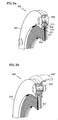
- FIG. 4 displays another alternative embodiment of the present invention. Similar to the other brush seals of the present invention, the figure displays a brush seal 400 with a back plate 401 , side plate 403 and bristle arrangement 405 .
- the plates 401 , 403 include grooves 411 , 413 that combine to form a cavity 419 for receiving a joint 409 of the bristle arrangement 405 .
- the abutting plates 401 , 403 also form a gap 421 for the bristles to extend past the plates 401 , 403 .
- the brush seal 400 uses features on the plates 401 , 403 to retain the plates 401 , 403 together.
- the back plate 401 includes an upper extension 437 with an angled surface 439 facing the side plate 403 .
- the side plate 403 has an angled surface 441 facing the back plate 401 .
- the annular side plate 403 has a larger diameter than the extension 437 .
- the operator must interference fit the side plate 403 into the back plate 401 using conventional techniques.
- the angled surfaces 439 , 441 of the plates 401 , 403 abut each other.
- the orientation of the angled surfaces 439 , 441 urges the plates 401 , 403 together. This orientation helps the plates 401 , 403 retain the bristle arrangement 405 therebetween.
- FIG. 5 displays another alternative embodiment of the present invention. Similar to the other brush seals of the present invention, the figure displays a brush seal 500 with a back plate 501 , side plate 503 and bristle arrangement 505 .
- the plates 501 , 503 include grooves 511 , 513 that combine to form a cavity 519 for receiving a joint 509 of the bristle arrangement 505 .
- the abutting plates 501 , 503 also form a gap 521 for the bristles to extend past the plates 501 , 503 .
- the brush seal 500 bonds the plates 501 , 503 together to retain the bristle arrangement 505 therebetween.
- Suitable bonding techniques include, for example, radial or axial welding, brazing and using an adhesive such as epoxy.
- FIG. 6 displays another alternative embodiment of the present invention. Similar to the other brush seals of the present invention, the figure displays a brush seal 600 with a back plate 601 , side plate 603 and bristle arrangement 605 .
- the brush seal 600 includes a snap ring assembly 643 to retain the bristle arrangement 605 between the plates 601 , 603 .
- the snap ring assembly 643 includes an annular flange 645 .
- the flange 645 can have an L-shape in cross-section.
- One section of the flange has a groove 647 .
- the operator assembles the brush seal 600 as follows. The operator places the flange 645 in a fixture (not shown). Then operator then inserts the back plate 601 against the flange 645 . The operator then places the joint 609 of the bristle arrangement 605 in the groove 613 of the back plate 601 . The operator then places the side plate 603 over the bristle arrangement 605 (ensuring the joint 609 enters the groove 611 ).
- the operator finally places one or more snap rings 649 in the groove 647 using conventional techniques.
- the snap rings 649 keep the side plate 603 against the back plate 601 to sandwich bristle arrangement 605 therebetween.
- the brush seal 600 could use any other suitable retainer.
- suitable retainers include wave washers (not shown), retaining rings (not shown) and radially oriented dowels (not shown) or spring pins (not shown) driven through the flange 645 .
- the flange 645 has been described as a separate subassembly from the back plate 601 , the back plate 601 and the flange 645 could also be one-piece.
- FIG. 7 displays another alternative embodiment of the present invention. Similar to the other brush seals of the present invention, the figure displays a brush seal 700 with a back plate 701 , side plate 703 and bristle arrangement 705 .
- the brush seal 700 also includes an annular support flange 735 for installing the brush seal 700 in the engine.
- the flange 735 mounts to the engine using suitable fasteners (not shown).
- threaded fasteners 751 secure the plates 701 , 703 to the flange 735 .
- the operator assembles the brush seal 700 as follows. The operator places the flange 735 in a fixture (not shown). Then operator then places the back plate 701 against the flange 735 . The operator then places the joint 709 of the bristle arrangement 705 in the groove 713 of the back plate 701 . The operator then places the side plate 703 over the bristle arrangement 705 (ensuring the joint 709 enters the groove 711 ).
- the operator inserts the fasteners 751 through the aligned openings in the plates 701 , 703 and into a threaded hole 753 in the flange 735 .
- the operator applies a sufficient torque to the fasteners 751 to keep the side plate 703 against the back plate 701 for sandwiching the bristle arrangement 705 therebetween.
- the brush seal 700 could utilize any other suitable type of fastener.
- the back plate 701 and the flange 735 could also be one-piece.
- a similar stand-alone design (not shown), incorporating only the plates 701 , 703 and not the flange 735 , could also be produced. This design would require the back plate 701 to have sufficient thickness for placing a threaded hole therein to receive the fastener.
- the brush seal 700 highlights another benefit of the present invention.
- the present invention allows a mechanic to replace the bristle arrangement 705 without replacing the other sub-assemblies of the brush seal 700 . Such replacement can occur after use of the brush seal 700 in the engine, or even before actual use.
- the mechanic replaces the bristle arrangement 705 as follows.
- the mechanic removes the fasteners 751 to detach the plates 701 , 703 from the flange 735 .
- the flange 735 preferably remains in the engine, while the plates 701 , 703 and the bristle arrangement 705 are removed. Separated from the flange 735 , the plates 701 , 703 no longer sandwich the bristle arrangement 705 .
- the mechanic can now remove the bristle arrangement 705 from the grooves 711 , 713 of the plates 701 , 703 . If necessary, the mechanic could have first removed the entire brush seal 700 from the engine by detaching the flange 735 from the engine, then performed the above steps.
- the mechanic could merely loosen the fasteners 751 (i.e. keeping the fasteners 751 in the threaded hole 753 ) sufficiently to remove the bristle arrangement 705 from the grooves 711 , 713 of the plates 701 , 703 .
- the mechanic After removing the bristle arrangement 705 , the mechanic then obtains a replacement bristle arrangement 705 . As a final step, the mechanic reassembles the brush seal 700 using the aforementioned assembly process.
Landscapes
- Engineering & Computer Science (AREA)
- General Engineering & Computer Science (AREA)
- Mechanical Engineering (AREA)
- Brushes (AREA)
- Sealing Devices (AREA)
Abstract
Description
Claims (28)
Priority Applications (3)
| Application Number | Priority Date | Filing Date | Title |
|---|---|---|---|
| US10/104,337 US7931276B2 (en) | 2002-03-20 | 2002-03-20 | Brush seal |
| EP03251735A EP1347218B1 (en) | 2002-03-20 | 2003-03-20 | Brush seal |
| DE60312066T DE60312066T2 (en) | 2002-03-20 | 2003-03-20 | brush seal |
Applications Claiming Priority (1)
| Application Number | Priority Date | Filing Date | Title |
|---|---|---|---|
| US10/104,337 US7931276B2 (en) | 2002-03-20 | 2002-03-20 | Brush seal |
Publications (2)
| Publication Number | Publication Date |
|---|---|
| US20030178778A1 US20030178778A1 (en) | 2003-09-25 |
| US7931276B2 true US7931276B2 (en) | 2011-04-26 |
Family
ID=27788392
Family Applications (1)
| Application Number | Title | Priority Date | Filing Date |
|---|---|---|---|
| US10/104,337 Active 2025-11-12 US7931276B2 (en) | 2002-03-20 | 2002-03-20 | Brush seal |
Country Status (3)
| Country | Link |
|---|---|
| US (1) | US7931276B2 (en) |
| EP (1) | EP1347218B1 (en) |
| DE (1) | DE60312066T2 (en) |
Cited By (9)
| Publication number | Priority date | Publication date | Assignee | Title |
|---|---|---|---|---|
| US20090218771A1 (en) * | 2008-03-03 | 2009-09-03 | Sparks Glenn D | Bristle and plate subassembly fixture and manufacturing method |
| US20100181043A1 (en) * | 2006-07-21 | 2010-07-22 | Ulrich Mueller | Regenerative air preheater with brush seal |
| US20110121519A1 (en) * | 2003-05-01 | 2011-05-26 | Justak John F | Seal with stacked sealing elements |
| US20130020770A1 (en) * | 2011-07-18 | 2013-01-24 | Jimmie Wade Hamilton | Brush seal |
| US8366115B2 (en) * | 2011-06-30 | 2013-02-05 | United Technologies Corporation | Repairable double sided brush seal |
| WO2014137431A1 (en) * | 2013-03-07 | 2014-09-12 | United Technologies Corporation | Brush seal repair method |
| US20160348581A1 (en) * | 2015-05-29 | 2016-12-01 | United Technologies Corporation | Retaining tab for diffuser seal ring |
| US9863538B2 (en) | 2015-04-27 | 2018-01-09 | United Technologies Corporation | Gas turbine engine brush seal with supported tip |
| US10137793B2 (en) * | 2015-09-23 | 2018-11-27 | ScienBiziP Consulting(Shenzhen) Co., Ltd. | Wiper ring and charging pile using same |
Families Citing this family (27)
| Publication number | Priority date | Publication date | Assignee | Title |
|---|---|---|---|---|
| DE10163804B4 (en) * | 2001-12-22 | 2005-07-07 | Mtu Aero Engines Gmbh | brush seal |
| US8181965B2 (en) * | 2002-06-27 | 2012-05-22 | United Technologies Corporation | Replaceable brush seal elements |
| US7270333B2 (en) * | 2002-11-27 | 2007-09-18 | United Technologies Corporation | Brush seal with adjustable clearance |
| US7000923B2 (en) * | 2004-01-09 | 2006-02-21 | United Technologies Corporation | Quick build brush seals |
| US7334311B2 (en) * | 2004-11-03 | 2008-02-26 | United Technologies Corporation | Method of forming a nested can brush seal |
| US7226054B2 (en) * | 2004-12-14 | 2007-06-05 | United Technologies Corporation | Clamp lock brush seal assembly |
| NO325031B1 (en) * | 2006-07-04 | 2008-01-21 | Ge Energy Norway As | Hydro Turbine |
| GB0619488D0 (en) * | 2006-10-03 | 2006-11-08 | Cross Mfg 1938 Company Ltd | Brush seal assembly |
| US20080136112A1 (en) * | 2006-12-08 | 2008-06-12 | United Technologies Corporation | Brush seal assemblies utilizing a threaded fastening method |
| US8727354B2 (en) * | 2008-01-15 | 2014-05-20 | United Technologies Corporation | Brush seal assembly and method of manufacturing same |
| US8632074B2 (en) * | 2008-07-14 | 2014-01-21 | Cross Manufacturing Company (1938) Limited | Method of forming a brush seal |
| US8505923B2 (en) * | 2009-08-31 | 2013-08-13 | Sealeze, A Unit of Jason, Inc. | Brush seal with stress and deflection accommodating membrane |
| US8534673B2 (en) * | 2010-08-20 | 2013-09-17 | Mitsubishi Power Systems Americas, Inc. | Inter stage seal housing having a replaceable wear strip |
| PL2718597T3 (en) | 2011-06-07 | 2018-02-28 | Sealeze, A Unit Of Jason Inc. | Brush seal cover assembly |
| ITCO20110058A1 (en) | 2011-12-05 | 2013-06-06 | Nuovo Pignone Spa | turbomachinery |
| US20140064937A1 (en) * | 2012-06-29 | 2014-03-06 | General Electric Company | Fan blade brush tip |
| FR3004892B1 (en) * | 2013-04-24 | 2015-10-09 | Crea | ARTICULATED COLLAR TRAPPING DEVICE |
| FR3004893B1 (en) * | 2013-04-24 | 2015-10-09 | Crea | TRAPPING DEVICE WITH MEANS OF JUNCTION |
| DE102013217581A1 (en) * | 2013-09-04 | 2015-03-05 | MTU Aero Engines AG | Sealing arrangement in an axial flow machine |
| DE102013220168B4 (en) * | 2013-10-07 | 2015-08-27 | MTU Aero Engines AG | Brush seal system for sealing a gap between relatively movable components of a thermal gas turbine |
| FR3011585B1 (en) * | 2013-10-09 | 2018-02-23 | Safran Aircraft Engines | AIRCRAFT TURBOMACHINE ASSEMBLY COMPRISING A FREESTRATED AXIAL HOLDING RING OF A BRUSH JOINT |
| DE112014005185T5 (en) | 2013-11-13 | 2016-07-21 | Foster Wheeler Usa Corporation | Method and system for furnace sealing |
| US9963994B2 (en) | 2014-04-08 | 2018-05-08 | General Electric Company | Method and apparatus for clearance control utilizing fuel heating |
| DE102014212174A1 (en) | 2014-06-25 | 2015-12-31 | MTU Aero Engines AG | Brush seal system for sealing a gap between relatively movable components of a turbomachine |
| US11168791B1 (en) * | 2016-09-02 | 2021-11-09 | Kurt Manufacturing Company, Inc. | Brush seal mounting for a vise jaw |
| US9995163B2 (en) * | 2016-09-02 | 2018-06-12 | United Technologies Corporation | Halo seal attached secondary seal cover arrangement |
| WO2018058068A1 (en) * | 2016-09-23 | 2018-03-29 | Federal-Mogul Powertrain Llc | Radial shaft seal assembly with debris exclusion member and method of construction thereof |
Citations (27)
| Publication number | Priority date | Publication date | Assignee | Title |
|---|---|---|---|---|
| US885032A (en) * | 1907-06-24 | 1908-04-21 | Sebastian Ziani De Ferranti | Fluid packing. |
| US3917150A (en) * | 1973-11-23 | 1975-11-04 | Rolls Royce 1971 Ltd | Seals and method of manufacture thereof |
| US4957301A (en) * | 1989-10-02 | 1990-09-18 | Whiting Roll-Up Door Mfg. Corp. | Non-crushable side seal members for a roll-up door |
| EP0469826A2 (en) | 1990-07-30 | 1992-02-05 | General Electric Company | Seal assembly for segmented turbine engine structures |
| US5135237A (en) * | 1989-04-05 | 1992-08-04 | Cross Manufacturing Company (1938) Limited | Brush seal with asymmetrical elements |
| US5165758A (en) * | 1991-08-07 | 1992-11-24 | Technetics Corporation | Place and bundle method for the manufacture of brush seals |
| US5183197A (en) * | 1991-08-07 | 1993-02-02 | Technetics Corp. | Bundle and place method for the manufacture of brush seals |
| US5316318A (en) * | 1992-04-23 | 1994-05-31 | Societe Nationale D'etude Et De Construction De Moteurs D'aviation "Snecma" | Annular brush gasket |
| US5425543A (en) * | 1993-09-17 | 1995-06-20 | Buckshaw; Dennis J. | Seal assembly for rotating shaft |
| US5474305A (en) * | 1990-09-18 | 1995-12-12 | Cross Manufacturing Company (1938) Limited | Sealing device |
| US5678898A (en) * | 1995-04-17 | 1997-10-21 | General Electric Company | Method for making a brush seal |
| US5704760A (en) * | 1996-03-26 | 1998-01-06 | United Technologies Corporation | Method and apparatus for improving the airsealing effectiveness in a turbine engine |
| US5752805A (en) * | 1995-07-28 | 1998-05-19 | Mtu Motoren- Und Turbinen-Union | Brush seal for turbo-engines |
| US5799952A (en) * | 1995-12-09 | 1998-09-01 | Rolls-Royce Plc | Brush seal |
| WO1999006673A1 (en) | 1997-07-30 | 1999-02-11 | Eg & G Sealol, Inc. | Improved brush seal and method of making same |
| US6027121A (en) * | 1997-10-23 | 2000-02-22 | General Electric Co. | Combined brush/labyrinth seal for rotary machines |
| US6196550B1 (en) * | 1999-02-11 | 2001-03-06 | Alliedsignal Inc. | Pressure balanced finger seal |
| US6257588B1 (en) * | 1998-09-22 | 2001-07-10 | General Electric Company | Brush seal and rotary machine including such brush seal |
| US6293553B1 (en) * | 1997-05-16 | 2001-09-25 | MTU MOTOREN-UND TURBINEN-UNION MüNCHEN GMBH | Brush seal |
| US6302400B1 (en) * | 1997-05-16 | 2001-10-16 | MTU MOTOREN-UND TURBINEN-UNION MüNCHEN GMBH | Brush-hair seal with a front plate and a bearing plate |
| US6331006B1 (en) * | 2000-01-25 | 2001-12-18 | General Electric Company | Brush seal mounting in supporting groove using flat spring with bifurcated end |
| US6378873B1 (en) * | 2000-06-02 | 2002-04-30 | General Electric Company | Low flow fluid film seal for hydrogen cooled generators |
| US6536773B2 (en) * | 2000-11-06 | 2003-03-25 | Advanced Components & Materials, Inc. | Compliant brush shroud assembly for gas turbine engine compressors |
| US6880829B1 (en) * | 2000-11-06 | 2005-04-19 | Advanced Components & Materials, Inc. | Compliant brush shroud assembly for gas turbine engine compressors |
| US6913265B2 (en) * | 2000-08-09 | 2005-07-05 | Advanced Components & Materials, Inc. | Brush seal assembly, method of manufacture and use |
| US6996885B2 (en) * | 2002-03-20 | 2006-02-14 | United Technologies Corporation | Method of making bristle arrangement for brush seal |
| US7340816B2 (en) * | 2002-02-12 | 2008-03-11 | United Technologies Corporation | Bristle arrangement for brush seal, method and assembly for making same, and method of making brush seal |
-
2002
- 2002-03-20 US US10/104,337 patent/US7931276B2/en active Active
-
2003
- 2003-03-20 DE DE60312066T patent/DE60312066T2/en not_active Expired - Lifetime
- 2003-03-20 EP EP03251735A patent/EP1347218B1/en not_active Expired - Lifetime
Patent Citations (28)
| Publication number | Priority date | Publication date | Assignee | Title |
|---|---|---|---|---|
| US885032A (en) * | 1907-06-24 | 1908-04-21 | Sebastian Ziani De Ferranti | Fluid packing. |
| US3917150A (en) * | 1973-11-23 | 1975-11-04 | Rolls Royce 1971 Ltd | Seals and method of manufacture thereof |
| US5135237A (en) * | 1989-04-05 | 1992-08-04 | Cross Manufacturing Company (1938) Limited | Brush seal with asymmetrical elements |
| US4957301A (en) * | 1989-10-02 | 1990-09-18 | Whiting Roll-Up Door Mfg. Corp. | Non-crushable side seal members for a roll-up door |
| EP0469826A2 (en) | 1990-07-30 | 1992-02-05 | General Electric Company | Seal assembly for segmented turbine engine structures |
| US5474305A (en) * | 1990-09-18 | 1995-12-12 | Cross Manufacturing Company (1938) Limited | Sealing device |
| US5165758A (en) * | 1991-08-07 | 1992-11-24 | Technetics Corporation | Place and bundle method for the manufacture of brush seals |
| US5183197A (en) * | 1991-08-07 | 1993-02-02 | Technetics Corp. | Bundle and place method for the manufacture of brush seals |
| US5316318A (en) * | 1992-04-23 | 1994-05-31 | Societe Nationale D'etude Et De Construction De Moteurs D'aviation "Snecma" | Annular brush gasket |
| US5425543A (en) * | 1993-09-17 | 1995-06-20 | Buckshaw; Dennis J. | Seal assembly for rotating shaft |
| US5678898A (en) * | 1995-04-17 | 1997-10-21 | General Electric Company | Method for making a brush seal |
| US5752805A (en) * | 1995-07-28 | 1998-05-19 | Mtu Motoren- Und Turbinen-Union | Brush seal for turbo-engines |
| US5799952A (en) * | 1995-12-09 | 1998-09-01 | Rolls-Royce Plc | Brush seal |
| US5704760A (en) * | 1996-03-26 | 1998-01-06 | United Technologies Corporation | Method and apparatus for improving the airsealing effectiveness in a turbine engine |
| US6293553B1 (en) * | 1997-05-16 | 2001-09-25 | MTU MOTOREN-UND TURBINEN-UNION MüNCHEN GMBH | Brush seal |
| US6302400B1 (en) * | 1997-05-16 | 2001-10-16 | MTU MOTOREN-UND TURBINEN-UNION MüNCHEN GMBH | Brush-hair seal with a front plate and a bearing plate |
| WO1999006673A1 (en) | 1997-07-30 | 1999-02-11 | Eg & G Sealol, Inc. | Improved brush seal and method of making same |
| US6027121A (en) * | 1997-10-23 | 2000-02-22 | General Electric Co. | Combined brush/labyrinth seal for rotary machines |
| US6257588B1 (en) * | 1998-09-22 | 2001-07-10 | General Electric Company | Brush seal and rotary machine including such brush seal |
| US6196550B1 (en) * | 1999-02-11 | 2001-03-06 | Alliedsignal Inc. | Pressure balanced finger seal |
| US6331006B1 (en) * | 2000-01-25 | 2001-12-18 | General Electric Company | Brush seal mounting in supporting groove using flat spring with bifurcated end |
| US6378873B1 (en) * | 2000-06-02 | 2002-04-30 | General Electric Company | Low flow fluid film seal for hydrogen cooled generators |
| US6913265B2 (en) * | 2000-08-09 | 2005-07-05 | Advanced Components & Materials, Inc. | Brush seal assembly, method of manufacture and use |
| US6536773B2 (en) * | 2000-11-06 | 2003-03-25 | Advanced Components & Materials, Inc. | Compliant brush shroud assembly for gas turbine engine compressors |
| US6880829B1 (en) * | 2000-11-06 | 2005-04-19 | Advanced Components & Materials, Inc. | Compliant brush shroud assembly for gas turbine engine compressors |
| US7340816B2 (en) * | 2002-02-12 | 2008-03-11 | United Technologies Corporation | Bristle arrangement for brush seal, method and assembly for making same, and method of making brush seal |
| US6996885B2 (en) * | 2002-03-20 | 2006-02-14 | United Technologies Corporation | Method of making bristle arrangement for brush seal |
| US7454822B2 (en) * | 2002-03-20 | 2008-11-25 | United Technologies Corporation | Method of making bristle arrangement for brush seal |
Cited By (14)
| Publication number | Priority date | Publication date | Assignee | Title |
|---|---|---|---|---|
| US8641045B2 (en) * | 2003-05-01 | 2014-02-04 | Advanced Technologies Group, Inc. | Seal with stacked sealing elements |
| US20110121519A1 (en) * | 2003-05-01 | 2011-05-26 | Justak John F | Seal with stacked sealing elements |
| US20100181043A1 (en) * | 2006-07-21 | 2010-07-22 | Ulrich Mueller | Regenerative air preheater with brush seal |
| US20090218771A1 (en) * | 2008-03-03 | 2009-09-03 | Sparks Glenn D | Bristle and plate subassembly fixture and manufacturing method |
| US8528178B2 (en) * | 2008-03-03 | 2013-09-10 | United Technologies Corporation | Bristle and plate subassembly fixture and manufacturing method |
| US8366115B2 (en) * | 2011-06-30 | 2013-02-05 | United Technologies Corporation | Repairable double sided brush seal |
| US20130020770A1 (en) * | 2011-07-18 | 2013-01-24 | Jimmie Wade Hamilton | Brush seal |
| WO2014137431A1 (en) * | 2013-03-07 | 2014-09-12 | United Technologies Corporation | Brush seal repair method |
| US10132183B2 (en) | 2013-03-07 | 2018-11-20 | United Technologies Corporation | Brush seal repair method |
| US11028719B2 (en) | 2013-03-07 | 2021-06-08 | Raytheon Technologies Corporation | Brush seal repair method |
| US9863538B2 (en) | 2015-04-27 | 2018-01-09 | United Technologies Corporation | Gas turbine engine brush seal with supported tip |
| US20160348581A1 (en) * | 2015-05-29 | 2016-12-01 | United Technologies Corporation | Retaining tab for diffuser seal ring |
| US10808612B2 (en) * | 2015-05-29 | 2020-10-20 | Raytheon Technologies Corporation | Retaining tab for diffuser seal ring |
| US10137793B2 (en) * | 2015-09-23 | 2018-11-27 | ScienBiziP Consulting(Shenzhen) Co., Ltd. | Wiper ring and charging pile using same |
Also Published As
| Publication number | Publication date |
|---|---|
| DE60312066T2 (en) | 2007-11-22 |
| EP1347218A3 (en) | 2004-04-28 |
| EP1347218B1 (en) | 2007-02-28 |
| DE60312066D1 (en) | 2007-04-12 |
| US20030178778A1 (en) | 2003-09-25 |
| EP1347218A2 (en) | 2003-09-24 |
Similar Documents
| Publication | Publication Date | Title |
|---|---|---|
| US7931276B2 (en) | Brush seal | |
| EP1672256B1 (en) | Clamp lock and brush seal assembly | |
| EP1930634A1 (en) | Brush seal assemblies utilizing a threaded fastening method | |
| EP1655526B1 (en) | Method of forming a brush seal | |
| EP1967698A2 (en) | Labyrinth and brush seal assembly, and associated mounting process | |
| US20060130323A1 (en) | Method of making bristle arrangement for brush seal | |
| US20140140859A1 (en) | Uber-cooled multi-alloy integrally bladed rotor | |
| EP2080938B1 (en) | Brush seal assembly and method of manufacturing same | |
| US7270333B2 (en) | Brush seal with adjustable clearance | |
| GB2463453A (en) | Turbocharger rotor assembly | |
| JP2002267023A (en) | Brush seal device | |
| EP1375983A2 (en) | Replaceable brush seal elements | |
| EP1363051B1 (en) | Brush seal and method of installing a brush seal in an apparatus. | |
| EP1706659B1 (en) | Quick build brush seals | |
| US5839643A (en) | Method of weld-recoulping front cover and pump shell of torque converter | |
| EP1353097A2 (en) | Brush seal | |
| EP1522773A1 (en) | Brush seal | |
| US20130051990A1 (en) | Bushing to repair circumferential flanged ring |
Legal Events
| Date | Code | Title | Description |
|---|---|---|---|
| AS | Assignment |
Owner name: UNITED TECHNOLOGIES CORPORATION, CONNECTICUT Free format text: ASSIGNMENT OF ASSIGNORS INTEREST;ASSIGNORS:SZYMBOR, JOHN A.;ADDIS, MARK E.;REEL/FRAME:012737/0097 Effective date: 20020226 |
|
| STCF | Information on status: patent grant |
Free format text: PATENTED CASE |
|
| FPAY | Fee payment |
Year of fee payment: 4 |
|
| MAFP | Maintenance fee payment |
Free format text: PAYMENT OF MAINTENANCE FEE, 8TH YEAR, LARGE ENTITY (ORIGINAL EVENT CODE: M1552); ENTITY STATUS OF PATENT OWNER: LARGE ENTITY Year of fee payment: 8 |
|
| AS | Assignment |
Owner name: RAYTHEON TECHNOLOGIES CORPORATION, MASSACHUSETTS Free format text: CHANGE OF NAME;ASSIGNOR:UNITED TECHNOLOGIES CORPORATION;REEL/FRAME:054062/0001 Effective date: 20200403 |
|
| AS | Assignment |
Owner name: RAYTHEON TECHNOLOGIES CORPORATION, CONNECTICUT Free format text: CORRECTIVE ASSIGNMENT TO CORRECT THE AND REMOVE PATENT APPLICATION NUMBER 11886281 AND ADD PATENT APPLICATION NUMBER 14846874. TO CORRECT THE RECEIVING PARTY ADDRESS PREVIOUSLY RECORDED AT REEL: 054062 FRAME: 0001. ASSIGNOR(S) HEREBY CONFIRMS THE CHANGE OF ADDRESS;ASSIGNOR:UNITED TECHNOLOGIES CORPORATION;REEL/FRAME:055659/0001 Effective date: 20200403 |
|
| MAFP | Maintenance fee payment |
Free format text: PAYMENT OF MAINTENANCE FEE, 12TH YEAR, LARGE ENTITY (ORIGINAL EVENT CODE: M1553); ENTITY STATUS OF PATENT OWNER: LARGE ENTITY Year of fee payment: 12 |
|
| AS | Assignment |
Owner name: RTX CORPORATION, CONNECTICUT Free format text: CHANGE OF NAME;ASSIGNOR:RAYTHEON TECHNOLOGIES CORPORATION;REEL/FRAME:064714/0001 Effective date: 20230714 |