EP1930552B1 - Ensemble de turbine pour faciliter la réduction de pertes dans des moteurs de turbines - Google Patents
Ensemble de turbine pour faciliter la réduction de pertes dans des moteurs de turbines Download PDFInfo
- Publication number
- EP1930552B1 EP1930552B1 EP07121300.3A EP07121300A EP1930552B1 EP 1930552 B1 EP1930552 B1 EP 1930552B1 EP 07121300 A EP07121300 A EP 07121300A EP 1930552 B1 EP1930552 B1 EP 1930552B1
- Authority
- EP
- European Patent Office
- Prior art keywords
- assembly
- shield
- stator ring
- coupled
- stator
- Prior art date
- Legal status (The legal status is an assumption and is not a legal conclusion. Google has not performed a legal analysis and makes no representation as to the accuracy of the status listed.)
- Not-in-force
Links
- 238000011144 upstream manufacturing Methods 0.000 claims description 23
- 239000012530 fluid Substances 0.000 claims description 5
- 238000007142 ring opening reaction Methods 0.000 claims description 4
- 238000000034 method Methods 0.000 description 7
- 230000008878 coupling Effects 0.000 description 6
- 238000010168 coupling process Methods 0.000 description 6
- 238000005859 coupling reaction Methods 0.000 description 6
- 230000001052 transient effect Effects 0.000 description 6
- 230000000712 assembly Effects 0.000 description 5
- 238000000429 assembly Methods 0.000 description 5
- 230000002411 adverse Effects 0.000 description 2
- 238000006073 displacement reaction Methods 0.000 description 2
- 238000011084 recovery Methods 0.000 description 2
- 230000000717 retained effect Effects 0.000 description 2
- 238000002485 combustion reaction Methods 0.000 description 1
- 230000000694 effects Effects 0.000 description 1
- 238000009413 insulation Methods 0.000 description 1
- 230000004048 modification Effects 0.000 description 1
- 238000012986 modification Methods 0.000 description 1
Images


Classifications
-
- F—MECHANICAL ENGINEERING; LIGHTING; HEATING; WEAPONS; BLASTING
- F01—MACHINES OR ENGINES IN GENERAL; ENGINE PLANTS IN GENERAL; STEAM ENGINES
- F01D—NON-POSITIVE DISPLACEMENT MACHINES OR ENGINES, e.g. STEAM TURBINES
- F01D25/00—Component parts, details, or accessories, not provided for in, or of interest apart from, other groups
- F01D25/08—Cooling; Heating; Heat-insulation
- F01D25/14—Casings modified therefor
-
- F—MECHANICAL ENGINEERING; LIGHTING; HEATING; WEAPONS; BLASTING
- F01—MACHINES OR ENGINES IN GENERAL; ENGINE PLANTS IN GENERAL; STEAM ENGINES
- F01D—NON-POSITIVE DISPLACEMENT MACHINES OR ENGINES, e.g. STEAM TURBINES
- F01D25/00—Component parts, details, or accessories, not provided for in, or of interest apart from, other groups
- F01D25/24—Casings; Casing parts, e.g. diaphragms, casing fastenings
- F01D25/246—Fastening of diaphragms or stator-rings
-
- F—MECHANICAL ENGINEERING; LIGHTING; HEATING; WEAPONS; BLASTING
- F05—INDEXING SCHEMES RELATING TO ENGINES OR PUMPS IN VARIOUS SUBCLASSES OF CLASSES F01-F04
- F05D—INDEXING SCHEME FOR ASPECTS RELATING TO NON-POSITIVE-DISPLACEMENT MACHINES OR ENGINES, GAS-TURBINES OR JET-PROPULSION PLANTS
- F05D2240/00—Components
- F05D2240/10—Stators
- F05D2240/12—Fluid guiding means, e.g. vanes
-
- Y—GENERAL TAGGING OF NEW TECHNOLOGICAL DEVELOPMENTS; GENERAL TAGGING OF CROSS-SECTIONAL TECHNOLOGIES SPANNING OVER SEVERAL SECTIONS OF THE IPC; TECHNICAL SUBJECTS COVERED BY FORMER USPC CROSS-REFERENCE ART COLLECTIONS [XRACs] AND DIGESTS
- Y10—TECHNICAL SUBJECTS COVERED BY FORMER USPC
- Y10T—TECHNICAL SUBJECTS COVERED BY FORMER US CLASSIFICATION
- Y10T29/00—Metal working
- Y10T29/49—Method of mechanical manufacture
- Y10T29/49229—Prime mover or fluid pump making
- Y10T29/49236—Fluid pump or compressor making
- Y10T29/49245—Vane type or other rotary, e.g., fan
Definitions
- This invention relates generally to turbine engines, and more particularly to methods and apparatus for reducing convection and aerodynamic bleed losses in turbine engines.
- the efficiency of at least some known turbines is at least partially affected by the clearances defined between the rotating components and stationary components.
- the magnitude of steady state clearances and transient radial clearances between the components may affect the turbine efficiency and/or operability margin.
- a large transient clearance, or a clearance with significant variation around the circumference of the rotating component may adversely decrease the turbine efficiency and may result in engine stalls.
- stator assemblies include a plurality of stator rings coupled together. Specifically, such stator rings are coupled to each other with fasteners which extend through flanges, spaced about the outer circumference of the stator rings. To facilitate slowing the transient thermal response of the stator rings, at least some known turbine assemblies include U-shaped shields that cover the flanges. The shields accomplish this by reducing the convective film coefficients of the stator rings such that the stator rings experience a slower temperature-displacement response.
- GB 2,144,492 A relates to a stator assembly for bounding the flowpath of a gas turbine engine and discloses features generally corresponding to the preamble of claim 1 herein.
- US 2004/0033133 A1 relates to a compressor bleed case assembly.
- a non-claimed method for assembling a compressor for use with a turbine includes coupling at least a first stator ring to a second stator ring via at least one fastener sized to extend through at least one stator ring opening.
- the method further includes coupling a shield assembly to at least one of the first stator ring and the second stator ring to facilitate reducing convection and aerodynamic bleed losses of the at least one stator ring.
- the shield assembly includes a downstream surface, a retaining portion, and a contoured upstream surface extending from the downstream surface to the retaining portion.
- a compressor assembly is provided in accordance with claim 1 herein.
- a turbine engine assembly is provided in accordance with claim 5 herein.
- FIG. 1 is a cross-sectional view of an exemplary turbofan engine assembly 10 having a longitudinal axis 11.
- turbofan engine assembly 10 includes a core gas turbine engine 12 that includes a high-pressure compressor 14, a combustor 16, and a high-pressure turbine 18.
- Turbofan engine assembly 10 also includes a low-pressure turbine 20 that is coupled axially downstream from core gas turbine engine 12, and a fan assembly 22 that is coupled axially upstream from core gas turbine engine 12.
- Fan assembly 22 includes an array of fan blades 24 that extend radially outward from a rotor disk 26.
- Engine 10 has an intake side 28 and an exhaust side 30.
- turbofan engine assembly 10 is a GE90 gas turbine engine that is available from General Electric Company, Cincinnati, Ohio.
- Core gas turbine engine 12, fan assembly 22, and low-pressure turbine 20 are coupled together by a first rotor shaft 31, and compressor 14 and high-pressure turbine 18 are coupled together by a second rotor shaft 32.
- Engine 10 is operable at a range of operating conditions between design operating conditions and off-design operating conditions.
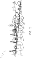
- FIG 2 is an enlarged cross-sectional view of a portion of high pressure compressor 14 including an exemplary shield assembly 100 coupled to a compressor stator body 58.
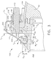
- Figure 3 is an enlarged cross-sectional view of shield assembly 100.
- compressor 14 includes a plurality of stages 50 wherein each stage 50 includes a row of circumferentially-spaced rotor blades 52 and a row of stator vane assemblies 56. Rotor blades 52 are typically supported by rotor disks 26, and are coupled to rotor shaft 32.
- Compressor 14 is surrounded by a casing 62 that supports stator vane assemblies 56. Casing 62 forms a portion of a compressor flow path extending through compressor 14.
- Casing 62 has rails 64 extending axially upstream and downstream of casing 62. To create a continuous compressor flow path, rails 64 are coupled to slots 66 defined in adjacent stator bodies 58, described in more detail below. Slots 66 are defined in at least one of an upstream surface and downstream surface of each stator body 58. Casing 62 is retained in position by coupling adjacent stator bodies 58 via flanges 76 and 104 and fasteners 106, as described in more detail below.
- Each stator vane assembly 56 includes a vane 74, a radial flange 76, and an annular stator body 58. Each radial flange 76 extends radially outward from stator body 58. As is known in the art, vanes 74 are oriented relative to a flow path through compressor 14 to control air flow therethrough. In addition, at least some vanes 74 are coupled to an inner shroud. Alternatively, compressor 14 may include a plurality of variable stator vanes utilized in lieu of fixed stator vanes 74.
- Each stator body 58 includes a radial flange 76 and an opening 102 formed therethrough. More specifically, in the exemplary embodiment, each opening 102 extends through each radial flange 76 of an upstream stator body 58.
- Stator body 58 may also include a stator ring or flange 104 that extends substantially axially from stator body 58. In the exemplary embodiment, stator ring or flange 104 extends generally upstream from a downstream stator body 58. More specifically, in the exemplary embodiment, each flange 104 of a downstream stator body 58 is coupled to each radial flange 76 of an adjacent upstream stator body 58 via a plurality of fasteners 106.
- fastener 106 extends through stator body opening 102 and through an opening 108 in stator body flange 104 to secure flange 104 to an upstream stator body 58.
- fastener 106 is a D-Head bolt that is secured in position with a breakaway nut 110.
- Fastener 106 has a fastener head 111 and a fastener body 112.
- Fastener head 111 has a thickness of T 1 .
- Fastener body 112 has a length of L 1 .
- fastener body length L 1 is greater that the length of the breakaway nut 110 to allow flange 104 and a nut 218 to be coupled to fastener 106, as described in more detail below.
- shield assembly 100 includes a shield 200 having an integrally-formed retaining portion 202, an aerodynamically contoured upstream surface 204, and a downstream surface 205.
- Upstream surface 204 extends between retaining portion 202 and downstream surface 205.
- Downstream surface 205 includes a slot 206 extending therethrough and that is sized to receive fastener 106 therethrough, as described in more detail below.
- Upstream surface 204 and downstream surface 205 each have a thickness of T 2 .
- Retaining portion 202 has a width of W 1 , a depth of D 1 , and a thickness of T 2 .
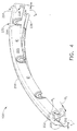
- Shield 200 is arcuate with a radius R 1 (shown in Fig. 5 ) where R 1 is larger that the outer radius of casing 62 such that shield 200 fits circumferentially about casing 62.
- shield assembly includes a plurality of arcuate shields 200, each with a radius of R 1 .
- stator body 58 is formed with a retaining channel 208 that extends circumferentially around stator body 58 and is defined between an annular lip 210 and a stepped portion 212 of body 58.
- Retaining channel 208 has a width W 2 .
- Lip 210 has a height of H 1 .
- Channel width W 2 is larger than retaining portion width W 1 such that retaining portion 202 may be inserted in retaining channel 208.
- Stepped portion 212 extends outward from body 58 and, in the exemplary embodiment, is formed with a plurality of shoulders 214 and 216. Shoulder 214 is counter-bored to a depth D 2 , where D 2 is substantially equal to fastener head thickness T 1 .
- shoulder 216 is counter-bored to a depth of D 3 .
- fastener head 111 is substantially flush with the outer edge of shoulder 214.
- retaining portion 202 is positioned in retaining channel 208, a portion of retaining portion 202 extends beyond shoulder 216.
- shield assembly 100 is positioned just downstream of an annular opening 219 in casing 62 and covers stator body opening 102, fastener 106, and flange 104.
- Shield 200 is retained in position by inserting shield retaining portion 202 into retaining channel 208.
- Lip 210 contacts shield 200 approximately at a point 220 where upstream surface 204 is coupled to retaining portion 202.
- lip 210 and upstream surface 204 form a continuous contour from stator body 58 at opening 219 to downstream surface 205.
- shield 200 is further secured by coupling shield 200 at slot 206 to flange 104 and breakaway nut 110 by utilizing shield slot 206.
- Shield 200 is secured in position by coupling nut 218 to fastener body 112 downstream of breakaway nut 110, slot 206, and flange opening 108.
- shield assembly 100 When shield assembly 100 is secured in position over stator body 58, shield assembly 100 creates an aerodynamic surface between stator body 58 and the airflow.
- FIG 4 is a perspective view of an exemplary shield assembly 100 including shield 200.
- Figure 5 is an exploded view of an exemplary shield assembly 100 coupled to stator body 58.
- Figure 6 is a second enlarged cross-sectional view of an exemplary shield assembly 100 coupled to stator body 58 at an overlap engagement 300.
- shield assembly 100 includes a first overlap portion 222 and a second overlap portion 224 coupled to shield 200.
- first overlap portion 222 is recessed from shield 200 by offset O 1 . More specifically, in the exemplary embodiment, offset O 1 is substantially equal to shield thickness T 2 .
- First overlap portion 222 has an upstream surface 226 and a downstream surface 228. Upstream surface 226 and downstream surface 228 each have a thickness of T 3 . In the exemplary embodiment, thickness T 3 is substantially equal to shield thickness T 2 .
- Upstream surface 226 is aerodynamically contoured and has a contour substantially equal to that of upstream surface 204.
- An aperture 230 having a radius R 2 extends through downstream surface 228.
- second overlap portion 224 is co-planar with shield 200.
- Second overlap portion has an upstream surface 232, a downstream surface 234, and a retaining portion 236.
- Upstream surface 232 and downstream surface 234 each have a thickness T 4 .
- thickness T 4 is equal to thickness T 2 .
- Upstream surface 232 is configured to have substantially the same aerodynamic contour as upstream surface 204.
- Retaining portion 236 is configured to have the same features and dimensions as retaining portion 202, described above.
- Downstream surface 234 has an aperture 238 extending therethrough. More specifically, in the exemplary embodiment, aperture 238 has a radius R 3 that is equal to aperture radius R 2 .
- first overlap portion 222 is inserted between second overlap portion 224 of an adjacent shield 200 and stator body 58.
- First overlap portion 222 and second overlap portion 224 are configured to mate and form overlap engagement 300.
- Aperture 230 is configured to align with aperture 238 of adjacent second overlap portion 224.
- Apertures 230 and 238 are further configured to align with a second opening 302 extending through stator body 58.
- flange 104 has a second opening 304 extending therethrough.
- Flange second opening 304 is sized to receive a retainer 306. More specifically, second opening 302 has a radius R 4 where R 4 is greater than R 2 and/or R 3 such that radius R 4 is sized to receive retainer 306.
- retainer 306 is a shank nut.
- Retainer 306 is positioned within stator body second opening 302 and flange second opening 304.
- Apertures 230 and 238 are configured to align with retainer 306 positioned in openings 302 and 304.
- Overlap portions 222 and 224 are secured to stator body by inserting a second fastener 308 through apertures 230, 238 and into retainer 306.
- second fastener 308 is a traditional bolt.
- shield slot 206 is aligned with stator body opening 102.
- shield assembly 100 facilitates reducing aerodynamic bleed losses by providing an aerodynamic surface over which air may flow and experience a pressure recovery. Further, stator body 58, stator body flange 104, and fastener 106 assembly is shielded from airflow of heated fluids. When in position, shield assembly 100 facilitates reducing the thermal expansion of stator body 58, which thereby facilitates slowing the growth of the stator during transient conditions and reducing tip clearances. When first overlap portion 222 and second overlap portion 224 form overlap engagement 300, overlap engagement 300 facilitates reducing leakage of air between shields 200 of shield assembly 100 and reduces aerodynamic windage losses over the shield.
- the above-described apparatus facilitates reducing losses in a compressor.
- the shield assembly facilitates minimizing losses by creating an aerodynamic surface in the air flow path and aiding in pressure recovery.
- a secondary air flow bled from the main compressor airflow flows over the aerodynamic surface.
- the airflow across the stator body increases in temperature of the stator body because of friction between the fluid and the surface of the stator body (windage).
- the shield assembly By coupling the shield assembly upstream of the stator body, the fluid has an aerodynamic surface across which to flow, reducing friction between the fluid and the stator body.
- the reduction in windage maintains the secondary air flow at a lower temperature than in other known compressors.
- the stator ring is shielded from the convection air flow.
- the overlapping shields create a low convection cavity around the stator ring such that the shield facilitates insulating the stator ring from the air flow. Therefore, the shield assembly also facilitates maintaining the desired stator thermal-displacement response to passively control the clearance between the rotating tip and the stationary inner surface of the compressor flow path. Because of the insulation effects of the shield assembly, the mass of the fastener at the stator body joints can be reduced while achieving the same time constant as a fastener with more mass.
- Exemplary embodiments of a method and apparatus to facilitate reducing losses in a compressor are described above in detail.
- the method and apparatus is not limited to the specific embodiments described herein, but rather, components of the method and apparatus may be utilized independently and separately from other components described herein.
- the shield assembly may also be used in combination with other turbine engine components, and is not limited to practice with only stator body assemblies as described herein. Rather, the present invention can be implemented and utilized in connection with many other windage loss reduction applications.
Landscapes
- Engineering & Computer Science (AREA)
- Mechanical Engineering (AREA)
- General Engineering & Computer Science (AREA)
- Structures Of Non-Positive Displacement Pumps (AREA)
- Turbine Rotor Nozzle Sealing (AREA)
Claims (6)
- Ensemble de compresseur (14) pour utilisation avec un ensemble de moteur à turbine, ledit ensemble de compresseur comprenant :au moins une bride (76) couplée à au moins une couronne de stator (104) via au moins une attache (106) calibrée pour s'étendre à travers au moins une ouverture (108) de la couronne de stator ; etun ensemble de protection (100) couplé à ladite au moins une couronne de stator, ledit ensemble de protection comprenant une surface aval (205), une partie de retenue (202) et une surface amont profilée (204) s'étendant de ladite surface aval à ladite partie de retenue ;caractérisé en ce que .ledit ensemble de protection (100) comprend un premier élément arqué (200) et un second élément arqué couplés l'un à l'autre, dans lequel ledit premier élément arqué comprend au moins une fente de retenue (206) qui y est définie, dans lequel ledit second élément arqué comprend en outre une ouverture (238) qui le traverse, dans lequel ledit premier élément arqué est couplé à ladite au moins une ouverture (304) de la couronne de stator et dans lequel ledit second élément arqué est couplé à au moins un dispositif de retenue (306) s'étendant à travers ladite au moins une couronne de stator.
- Ensemble de compresseur (14) selon la revendication 1, dans lequel ladite partie de retenue (202) de l'ensemble de protection est insérée dans une rainure définie dans ladite au moins une couronne de stator (104) de sorte que ledit ensemble de protection protège sensiblement ladite au moins une couronne de stator de l'air s'écoulant au niveau de ladite au moins une couronne de stator.
- Ensemble de compresseur (14) selon la revendication 1 ou la revendication 2, dans lequel ladite au moins une bride (76) est couplée à ladite au moins une couronne de stator (104) de sorte que ladite bride s'étende en aval de ladite couronne de stator et ledit ensemble de protection (100) est couplé à ladite au moins une couronne de stator pour faciliter la réduction des pertes de fardage de ladite au moins une couronne de stator.
- Ensemble de compresseur (14) selon l'une quelconque des revendications 1 à 3, dans lequel ledit ensemble de protection (100) comprend en outre une pluralité de segments de protection, dans lequel chaque segment de protection comprend un premier élément arqué, un second élément arqué et un corps qui s'étend entre eux, dans lequel ledit premier élément arqué d'un premier segment de protection se couple audit second élément arqué d'un second segment de protection de sorte que ladite perte de fluide entre ledit premier segment de protection et ledit second segment de protection soit facile à réduire.
- Ensemble de moteur à turbine (12) comprenant un ensemble de compresseur (14) selon l'une quelconque des revendications précédentes.
- Ensemble de moteur à turbine selon la revendication 5, dans lequel ladite fente de retenue (206) de l'ensemble de protection est couplée à ladite au moins une ouverture (108) de la couronne de stator, dans lequel ladite fente de retenue est fixée en place avec au moins un écrou (110) couplé à ladite au moins une attache (112).
Applications Claiming Priority (1)
| Application Number | Priority Date | Filing Date | Title |
|---|---|---|---|
| US11/564,027 US7704038B2 (en) | 2006-11-28 | 2006-11-28 | Method and apparatus to facilitate reducing losses in turbine engines |
Publications (3)
| Publication Number | Publication Date |
|---|---|
| EP1930552A2 EP1930552A2 (fr) | 2008-06-11 |
| EP1930552A3 EP1930552A3 (fr) | 2013-12-18 |
| EP1930552B1 true EP1930552B1 (fr) | 2016-03-23 |
Family
ID=39106185
Family Applications (1)
| Application Number | Title | Priority Date | Filing Date |
|---|---|---|---|
| EP07121300.3A Not-in-force EP1930552B1 (fr) | 2006-11-28 | 2007-11-22 | Ensemble de turbine pour faciliter la réduction de pertes dans des moteurs de turbines |
Country Status (4)
| Country | Link |
|---|---|
| US (1) | US7704038B2 (fr) |
| EP (1) | EP1930552B1 (fr) |
| JP (1) | JP5491693B2 (fr) |
| CA (1) | CA2611825C (fr) |
Families Citing this family (11)
| Publication number | Priority date | Publication date | Assignee | Title |
|---|---|---|---|---|
| US8388308B2 (en) * | 2007-10-30 | 2013-03-05 | General Electric Company | Asymmetric flow extraction system |
| US8820046B2 (en) * | 2009-10-05 | 2014-09-02 | General Electric Company | Methods and systems for mitigating distortion of gas turbine shaft |
| FR2991385B1 (fr) * | 2012-06-05 | 2017-04-28 | Snecma | Contre-plaque, et turbomachine comprenant une contre-plaque |
| US9322415B2 (en) | 2012-10-29 | 2016-04-26 | United Technologies Corporation | Blast shield for high pressure compressor |
| US10294808B2 (en) * | 2016-04-21 | 2019-05-21 | United Technologies Corporation | Fastener retention mechanism |
| US10494936B2 (en) * | 2016-05-23 | 2019-12-03 | United Technologies Corporation | Fastener retention mechanism |
| DE102016213813A1 (de) * | 2016-07-27 | 2018-02-01 | MTU Aero Engines AG | Verkleidungselement einer Strömungsmaschine und entsprechende Verbindungsanordnung |
| US10539153B2 (en) * | 2017-03-14 | 2020-01-21 | General Electric Company | Clipped heat shield assembly |
| US10704416B2 (en) * | 2018-07-13 | 2020-07-07 | Raytheon Technologies Corporation | Conformal heat shield for gas turbine engine |
| US11021962B2 (en) * | 2018-08-22 | 2021-06-01 | Raytheon Technologies Corporation | Turbulent air reducer for a gas turbine engine |
| IT202100009716A1 (it) * | 2021-04-16 | 2022-10-16 | Ge Avio Srl | Copertura di un dispositivo di fissaggio per una giunzione flangiata |
Citations (1)
| Publication number | Priority date | Publication date | Assignee | Title |
|---|---|---|---|---|
| US20060193721A1 (en) * | 2005-02-25 | 2006-08-31 | Snecma | Turbomachine inner casing fitted with a heat shield |
Family Cites Families (10)
| Publication number | Priority date | Publication date | Assignee | Title |
|---|---|---|---|---|
| US4190397A (en) * | 1977-11-23 | 1980-02-26 | General Electric Company | Windage shield |
| US4525997A (en) * | 1983-08-01 | 1985-07-02 | United Technologies Corporation | Stator assembly for bounding the flow path of a gas turbine engine |
| FR2624913B1 (fr) * | 1987-12-16 | 1990-04-20 | Snecma | Dispositif de fixation a vis d'une piece de revolution sur une bride annulaire de turbomachine |
| US5090865A (en) * | 1990-10-22 | 1992-02-25 | General Electric Company | Windage shield |
| US5161565A (en) * | 1991-12-16 | 1992-11-10 | Dresser-Rand Company | Cover and retainer for a compressor valve |
| US5259725A (en) * | 1992-10-19 | 1993-11-09 | General Electric Company | Gas turbine engine and method of assembling same |
| FR2794816B1 (fr) * | 1999-06-10 | 2001-07-06 | Snecma | Stator de compresseur a haute pression |
| US6442941B1 (en) * | 2000-09-11 | 2002-09-03 | General Electric Company | Compressor discharge bleed air circuit in gas turbine plants and related method |
| US6783324B2 (en) * | 2002-08-15 | 2004-08-31 | General Electric Company | Compressor bleed case |
| US7094020B2 (en) * | 2004-09-15 | 2006-08-22 | General Electric Company | Swirl-enhanced aerodynamic fastener shield for turbomachine |
-
2006
- 2006-11-28 US US11/564,027 patent/US7704038B2/en active Active
-
2007
- 2007-11-22 EP EP07121300.3A patent/EP1930552B1/fr not_active Not-in-force
- 2007-11-22 JP JP2007302430A patent/JP5491693B2/ja not_active Expired - Fee Related
- 2007-11-22 CA CA2611825A patent/CA2611825C/fr not_active Expired - Fee Related
Patent Citations (1)
| Publication number | Priority date | Publication date | Assignee | Title |
|---|---|---|---|---|
| US20060193721A1 (en) * | 2005-02-25 | 2006-08-31 | Snecma | Turbomachine inner casing fitted with a heat shield |
Also Published As
| Publication number | Publication date |
|---|---|
| EP1930552A2 (fr) | 2008-06-11 |
| JP5491693B2 (ja) | 2014-05-14 |
| US7704038B2 (en) | 2010-04-27 |
| US20080120841A1 (en) | 2008-05-29 |
| EP1930552A3 (fr) | 2013-12-18 |
| JP2008133829A (ja) | 2008-06-12 |
| CA2611825C (fr) | 2015-06-23 |
| CA2611825A1 (fr) | 2008-05-28 |
Similar Documents
| Publication | Publication Date | Title |
|---|---|---|
| EP1930552B1 (fr) | Ensemble de turbine pour faciliter la réduction de pertes dans des moteurs de turbines | |
| EP3693553B1 (fr) | Assemblage de joint à languettes avec contrôle de fuite | |
| US6935836B2 (en) | Compressor casing with passive tip clearance control and endwall ovalization control | |
| US7094029B2 (en) | Methods and apparatus for controlling gas turbine engine rotor tip clearances | |
| US10655495B2 (en) | Spline for a turbine engine | |
| CA2712113C (fr) | Scellement et refroidissement au joint entre les segments annulaires d'enveloppe de turbine | |
| EP1630385B1 (fr) | Procédé et appareil pour maintenir le jeu des extrémités des aubes d'un rotor de turbine | |
| US20180355755A1 (en) | Spline for a turbine engine | |
| EP3412871B1 (fr) | Joint pour aube directrice de turbine à gaz | |
| US10577943B2 (en) | Turbine engine airfoil insert | |
| US20200088037A1 (en) | Turbine engine with annular cavity | |
| US20170306768A1 (en) | Turbine engine shroud assembly | |
| US11377957B2 (en) | Gas turbine engine with a diffuser cavity cooled compressor | |
| US20180340437A1 (en) | Spline for a turbine engine | |
| US20180355754A1 (en) | Spline for a turbine engine | |
| US20180355741A1 (en) | Spline for a turbine engine | |
| US20180347375A1 (en) | Airfoil with tip rail cooling | |
| EP3071794B1 (fr) | Extension de carénage interne à éléments multiples pour une turbomachine | |
| EP3023594B1 (fr) | Ensemble de stator avec interface de tampon pour une turbine à gaz | |
| EP3287605B1 (fr) | Joint de bordure pour moteur à turbine à gaz | |
| EP3578759B1 (fr) | Profil aérodynamique et procédé associé pour diriger un flux de refroidissement | |
| CN114144573B (zh) | 涡轮机械整流器级,带有具有根据叶片的取向的可变截面的冷却空气泄漏通道 |
Legal Events
| Date | Code | Title | Description |
|---|---|---|---|
| PUAI | Public reference made under article 153(3) epc to a published international application that has entered the european phase |
Free format text: ORIGINAL CODE: 0009012 |
|
| AK | Designated contracting states |
Kind code of ref document: A2 Designated state(s): AT BE BG CH CY CZ DE DK EE ES FI FR GB GR HU IE IS IT LI LT LU LV MC MT NL PL PT RO SE SI SK TR |
|
| AX | Request for extension of the european patent |
Extension state: AL BA HR MK RS |
|
| RIN1 | Information on inventor provided before grant (corrected) |
Inventor name: RULLI, SAMUEL Inventor name: KARAFILLIS, APOSTOLOS Inventor name: LIU, HSIN-TUAN Inventor name: RING, MATTHEW JOSEPH Inventor name: KIRK, CORY |
|
| PUAL | Search report despatched |
Free format text: ORIGINAL CODE: 0009013 |
|
| AK | Designated contracting states |
Kind code of ref document: A3 Designated state(s): AT BE BG CH CY CZ DE DK EE ES FI FR GB GR HU IE IS IT LI LT LU LV MC MT NL PL PT RO SE SI SK TR |
|
| AX | Request for extension of the european patent |
Extension state: AL BA HR MK RS |
|
| RIC1 | Information provided on ipc code assigned before grant |
Ipc: F01D 25/24 20060101ALI20131114BHEP Ipc: F01D 11/08 20060101AFI20131114BHEP |
|
| 17P | Request for examination filed |
Effective date: 20140618 |
|
| RBV | Designated contracting states (corrected) |
Designated state(s): AT BE BG CH CY CZ DE DK EE ES FI FR GB GR HU IE IS IT LI LT LU LV MC MT NL PL PT RO SE SI SK TR |
|
| AKX | Designation fees paid |
Designated state(s): DE FR GB |
|
| 17Q | First examination report despatched |
Effective date: 20150206 |
|
| GRAP | Despatch of communication of intention to grant a patent |
Free format text: ORIGINAL CODE: EPIDOSNIGR1 |
|
| INTG | Intention to grant announced |
Effective date: 20151110 |
|
| GRAS | Grant fee paid |
Free format text: ORIGINAL CODE: EPIDOSNIGR3 |
|
| GRAA | (expected) grant |
Free format text: ORIGINAL CODE: 0009210 |
|
| AK | Designated contracting states |
Kind code of ref document: B1 Designated state(s): DE FR GB |
|
| REG | Reference to a national code |
Ref country code: GB Ref legal event code: FG4D |
|
| REG | Reference to a national code |
Ref country code: DE Ref legal event code: R096 Ref document number: 602007045394 Country of ref document: DE |
|
| REG | Reference to a national code |
Ref country code: FR Ref legal event code: PLFP Year of fee payment: 10 |
|
| REG | Reference to a national code |
Ref country code: DE Ref legal event code: R097 Ref document number: 602007045394 Country of ref document: DE |
|
| PLBE | No opposition filed within time limit |
Free format text: ORIGINAL CODE: 0009261 |
|
| STAA | Information on the status of an ep patent application or granted ep patent |
Free format text: STATUS: NO OPPOSITION FILED WITHIN TIME LIMIT |
|
| PGFP | Annual fee paid to national office [announced via postgrant information from national office to epo] |
Ref country code: GB Payment date: 20161128 Year of fee payment: 10 Ref country code: DE Payment date: 20161123 Year of fee payment: 10 Ref country code: FR Payment date: 20161123 Year of fee payment: 10 |
|
| 26N | No opposition filed |
Effective date: 20170102 |
|
| REG | Reference to a national code |
Ref country code: DE Ref legal event code: R119 Ref document number: 602007045394 Country of ref document: DE |
|
| GBPC | Gb: european patent ceased through non-payment of renewal fee |
Effective date: 20171122 |
|
| REG | Reference to a national code |
Ref country code: FR Ref legal event code: ST Effective date: 20180731 |
|
| PG25 | Lapsed in a contracting state [announced via postgrant information from national office to epo] |
Ref country code: DE Free format text: LAPSE BECAUSE OF NON-PAYMENT OF DUE FEES Effective date: 20180602 Ref country code: FR Free format text: LAPSE BECAUSE OF NON-PAYMENT OF DUE FEES Effective date: 20171130 |
|
| PG25 | Lapsed in a contracting state [announced via postgrant information from national office to epo] |
Ref country code: GB Free format text: LAPSE BECAUSE OF NON-PAYMENT OF DUE FEES Effective date: 20171122 |