EP1930132A1 - Device, in particular for positioning objects - Google Patents
Device, in particular for positioning objects Download PDFInfo
- Publication number
- EP1930132A1 EP1930132A1 EP07017249A EP07017249A EP1930132A1 EP 1930132 A1 EP1930132 A1 EP 1930132A1 EP 07017249 A EP07017249 A EP 07017249A EP 07017249 A EP07017249 A EP 07017249A EP 1930132 A1 EP1930132 A1 EP 1930132A1
- Authority
- EP
- European Patent Office
- Prior art keywords
- supports
- pair
- pairs
- base part
- side ends
- Prior art date
- Legal status (The legal status is an assumption and is not a legal conclusion. Google has not performed a legal analysis and makes no representation as to the accuracy of the status listed.)
- Ceased
Links
Images


Classifications
-
- B—PERFORMING OPERATIONS; TRANSPORTING
- B25—HAND TOOLS; PORTABLE POWER-DRIVEN TOOLS; MANIPULATORS
- B25J—MANIPULATORS; CHAMBERS PROVIDED WITH MANIPULATION DEVICES
- B25J17/00—Joints
- B25J17/02—Wrist joints
- B25J17/0208—Compliance devices
- B25J17/0216—Compliance devices comprising a stewart mechanism
-
- Y—GENERAL TAGGING OF NEW TECHNOLOGICAL DEVELOPMENTS; GENERAL TAGGING OF CROSS-SECTIONAL TECHNOLOGIES SPANNING OVER SEVERAL SECTIONS OF THE IPC; TECHNICAL SUBJECTS COVERED BY FORMER USPC CROSS-REFERENCE ART COLLECTIONS [XRACs] AND DIGESTS
- Y10—TECHNICAL SUBJECTS COVERED BY FORMER USPC
- Y10T—TECHNICAL SUBJECTS COVERED BY FORMER US CLASSIFICATION
- Y10T74/00—Machine element or mechanism
- Y10T74/20—Control lever and linkage systems
- Y10T74/20207—Multiple controlling elements for single controlled element
- Y10T74/20372—Manual controlling elements
- Y10T74/20378—Planar surface with orthogonal movement or rotation
Definitions
- the present invention relates to a device, in particular for positioning at least one object, with adjustable-length supports, with a base part, with a receptacle for the object, wherein the supports are arranged between the base part and the receptacle and articulated there, and with a drive and a control for adjusting the supports, according to patent DE 10 2006 011 823.5 ,
- Such devices for positioning serve to spend an object in a desired position and to hold in this.
- Such an object is often a workpiece, which is brought by means of the device in this position and held there, so that then a processing, for. B. by a robot can be done.
- the object can be moved into further positions in which further processing steps can take place.
- the object may also be a tool that is moved to different positions for machining a workpiece.
- a possible field of use of a device for positioning objects can be found, for example, in the automotive industry, where, for example, bodies, etc., are automatically processed by robots in automatic production lines.
- the supports are adjustable in length and can be swiveled in the room.
- the movements of the supports are generated by drives, control devices control the movement sequence and the end coordinates of the desired position.
- a device for positioning an object comprising a plate with a plurality of independently arranged supports on which a workpiece, which may be composed of several parts, can be positioned.
- a control device is provided which measures the force introduced into the supports due to the weight of the object and adjusts the supports accordingly, so that the weight of the object can be maintained, even if, for example, external changing forces act on the object .
- Two or more of the pillars may be mechanically coupled together to produce a particular movement of the object while constraining degrees of freedom.
- the mutually coupled supports are at an angle to each other, so that they can attack bending or torsional moments on them.
- the known device also requires a high cost because of the control and regulating device.
- the supports must be equipped with sensors that send appropriate signals to the control device. If objects of greater weight are to be positioned, the stiffness requirements are also increased and it requires a correspondingly more complex control and regulating device.
- the device can not respond flexibly to a wide variety of requirements and applications, whereby the application possibilities of this device are relatively limited.
- the object of the invention is to further improve the device of the type mentioned, wherein the stability and flexibility for different applications increases and the manufacturing and maintenance costs are reduced.
- a device of the type in question is further developed such that at least one support pair of two supports is provided and that the two supports of the support pair extend parallel, so that the shape of a parallelogram results.
- each pair of parallel supports a pair of supports is formed, which has the shape of a parallelogram.
- each support individually absorbs forces, but on the other hand considered each pair of supports as a couple of forces can also take a moment.
- the drive and control device form a spatial unit with each other.
- the control device arranged spatially separated from the drive device, optionally housed in a control cabinet.
- the supports of the pair of supports are the receiving side and basisteil lake movable d. H. hinged, so that the adjustment of the object can be made in the room.
- the receptacle itself is firmly connected to the receiving end of the pair of supports, so that the individual supports can pivot about their hinge axis, but the spatial distance of the joint axes is fixed.
- the recording can thus be moved in all three directions of the spatial coordinate system, and the angular position of the recording to Baisteil is adjustable according to the need.
- the base part can also be changed in its position.
- the base part may, according to one embodiment, be in the form of a platform on the upper side of which the pair of supports is arranged. It is also conceivable, however, any other form of structure that allows a spatially defined arrangement of the pair of supports. For greater stability with regard to objects of different sizes to be positioned and weight, it is advantageous if six supports are provided, as this high torsional moments are avoided in the supports and tensile and compressive forces dominate. In the sense of minimizing the production costs, it then makes sense again to design these six supports as three pairs of supports.
- An embodiment of the device according to the invention with three support pairs which is advantageous in terms of a compact design, is characterized in that the base part-side ends and the receptacle-side ends of the three support pairs are each arranged in the sense of an imaginary triangle.
- the imaginary triangle according to the invention may be equilateral.
- the imaginary triangle formed by the base-part-side ends and the imaginary triangle formed by the receiving-side ends may be twisted with each other. Within certain limits, this makes it possible to minimize the base area of the base platform plus the other components.
- a positioning device can flexibly respond to different requirements by changing the twist angle between the receiving-side imaginary triangle and the base-part-side imaginary triangle. The smaller the twist angle, the higher the stiffness. Also, the rigidity in the horizontal direction and the flexural rigidity are increased. Investigations have shown that the distribution of forces on the six supports in the twisted variant is more uniform.
- a further advantageous embodiment of the device according to the invention with at least three pairs of supports is that the base part-side ends of at least two pairs of columns facing each other on a first and second line, the parallel to each other (pivot axes B) and the base part-side ends of the third pair of supports lie on a third line which is perpendicular to the first and second line and which forms the pivot axis (B) of the third pair of supports.
- the base-part-side ends of the opposing pairs of supports can have no distance from each other in the direction of their parallel bearing axes, so that it is possible to speak of a symmetry in this respect.
- the base-part-side ends of the opposite pairs of supports could also be spaced apart in the direction of their parallel bearing axes, so that a staggered arrangement occurs.
- the receiving ends of the support pairs - as well as in the arrangement in the sense of an imaginary triangle - to achieve a high stability a smaller distance from each other than the base part-side ends of the support pairs.
- the arrangement of the base-part-side ends of the pairs of posts could be repeated by their receiving-side ends, but only at shorter intervals.
- the receiving-side ends of the two opposite pairs of supports can also form an aligned line on an imaginary line parallel to the bearing axes of the base-part-side ends of the opposite pairs of supports. In this way, it is possible to provide particularly space-saving recordings for objects.
- a further advantageous embodiment of the invention may be that the receiving ends of each of the two opposing pairs of supports at least partially overlap an imaginary, imaginary line extending parallel to the pivot axis or the first and second lines of the base-part-side end of the respectively opposite pair of supports;
- the receiving-side ends of the supports of the opposite pairs of supports can be on both sides of the imaginary fourth line, wherein the supports of the two pairs of supports cross the imaginary fourth line.
- the stability-increasing variant with the imaginary fourth line crossing supports and also the variant of the aligned row of receiving ends assume that a certain distance between the receiving side and basesteil solutionen ends of a pair of columns of the two opposite pairs of supports must be parallel to the bearing axes. If this is not present, then at least the opposite pair of supports are to be spaced parallel to the bearing axis.
- the plate-shaped base member may be formed rectangular and also the recording. Also contemplated are circular or elliptical or arbitrarily shaped images as a workpiece or tool carrier.
- All support pairs of the previously described embodiments could be cost-effectively equipped with only one drive and control unit or with at least one drive unit and associated encoder for detecting the drive position.
- another variant provides for driving at least two supports of a support pair separately.
- the support pair with the two separately driven supports could be the pair of supports extending orthogonally to the two opposite pairs of supports.
- a pivotal movement of the recording could be brought about to counteract bending moments caused by the object, or it could be exercised a controlled pivoting movement on the object as an additional possibility of movement.
- a largely directional independence is established.
- a next advantageous embodiment of the device according to the invention is concerned with the construction of the base part in the form of a body, on the circumference of which the pair of supports or a plurality of pairs of supports is / are arranged.
- the base part may have the shape of a cube, wherein three side surfaces of the cube are each associated with a pair of columns and these extend approximately orthogonal to each other.
- the support pairs can also be assigned to more than three sides of the cube. Also conceivable would be different shots for certain support pairs, different function assignments. While tools are attached to two pairs of supports, the remaining pairs of supports can hold a component on their common receptacle or on their separate receptacles.
- FIGS. 1 to 4, 6, 8, 12 to 14 show an apparatus for positioning objects 1 (see in particular FIGS. 6, 8), with length-adjustable supports 2, with a base part 3 and with a receptacle 4 for the object 1.
- the supports 2 are arranged between the base part 3 and the receptacle 4 and mounted on these each movable, as will be explained in more detail below.
- At least one support pair 5 with two supports 2 extending in parallel is provided.
- the support pair 5 forms, like the other pairs of columns, the shape of a parallelogram.
- a drive and control unit 6 is provided according to the invention; in the drive and control are summarized, see in particular Fig. 2.
- At least one drive unit is associated with an encoder which serves to detect the drive position.
- pivot bearings 8, 9 are provided (see Fig. 1, in which the device is shown schematically), which pivot bearings 8 are fixedly connected to the receptacle, which means that the distance between the pivot bearing 8 is fixed , Both pivot bearings 8 of the pair of supports 5 have a common pivot axis A.
- pivot bearings 11, 12, 13 are provided, of which the pivot bearings 11, 13 have a pivot axis B. In the position shown in Fig. 1, the distance is the Swivel axes 8 to the pivot axes 11, 13 denoted by ⁇ L.
- the distance .DELTA.L can be varied, so that the distance of the pivot axes 8; 11, 13 can be increased from one another to ⁇ L 1 .
- This can be done once by the base part 3 is lowered when quasi detained receiving part 4, so that the pivot axes 11, 13 come to lie on the line C, and on the other characterized in that when holding the base part 3, the receiving part 4 from the distance .DELTA.L is raised to the distance .DELTA.L 1 .
- the lowering of the base part 3 can for example be done when certain work is still to be made on the object which is mounted on the receiving part 4, thus the receiving part 4 still has to remain stationary in the room. Normally, however, the base part 3 is fixed, and the receiving part 4 moves.
- the device 10 shown in FIG. 2 comprises three pairs of supports 5, 5a, 5b, which are formed substantially the same, wherein the supports 2 of each support pair 5, 5a, 5b each span a plane that forms a triangle with the respective other planes.
- the base part-side ends of the supports are fixedly secured to U-shaped first bearing blocks 14, 15 and that on the outside of each crossbar 16, 17.
- On the legs 18, 19 of each bracket 15, 16 (the legs of the bearing block 15 are hidden) are ever an axis of rotation 20 is received, which are rotatably mounted in a support bracket 21, which in turn is mounted on an axis 22 fixedly connected to the base part 3 support brackets 23.
- the axis 22 extends in the plane which span the supports of the pair of supports 5, or parallel thereto and moreover also parallel to the plane of the base part.
- two support brackets 23a and 23b are provided, in which the axle 22 is rotatably mounted; via the axis 22 of the support bracket 21 is rotatably mounted, which is located between the support brackets 23a, 23b, and on this support bracket 21, the bearing blocks 14, 15 are pivotally mounted, wherein the pivot axes 20 or axes 20 transverse or perpendicular to the axis 22 , Together, the support brackets 23a, 23b, the support bracket 21 and the bearing blocks 14, 15 with the pivot axes 20 and 22 form a combined universal joint for a pair of columns 5, 5a, 5b.
- the pivot axes must then be aligned kinematically equivalent to the pivot axes 20 and 22.
- the pivot axes For each of the three pairs of supports 5, 5a, 5b only one drive and control unit 6 or at least one drive unit with associated encoder for detecting the drive position 6 is provided, wherein the two supports 2 each pair of supports 5, 5a and 5b with the drive and control unit are synchronized.
- the parallelism of the two supports 2 all pairs of columns 5, 5a and 5b is brought about by the fact that the distance between the base-part-side ends 10 and the receiving-side ends 7 of the two supports 2 of all pairs of supports is the same in each case.
- the universal joint 24 includes a first hinge part 25 which is fixedly connected to the extendable portion 26 of each support. At distantly opposite generatrices of the first joint part 25 tabs 27, 28 are arranged, here formed, which receive a pivot axis 29, around which a between the flaps 27, 28 located Kardangelenkish 30 can rotate.
- a second hinge part 31 is fixed, which has the tabs 27, 28 corresponding tabs 32 which project to the first hinge part 25 out, ie, away from the receiving part 4.
- the gimbal 30 is also located between the two tabs 32 and is pivotally mounted on these via an axis 33, wherein the axes 29 and 33 are perpendicular to each other and can either intersect at one point or intersect at a defined distance from each other.
- both universal joints can be combined to form a combined universal joint, in which the two universal joints are rigidly coupled to each other on their common pivot axis 33 or both universal joints 30 are combined in one component, similar to the support bracket 21.
- the base part 3 (FIG. 2) is designed in the sense of a hexagonal platform; the receptacle 4 is formed as a circular platform with mounting holes 34.
- a pivot bearing 15, 16 is provided, whose distance corresponds to the distance between the two universal joints 24 at the receiving end 7 of the supports 2.
- the pivot bearings 15, 16 are mounted with their bearing axes so that they are perpendicular to the pivot axis 22 pivotally.
- the pivot axis 22 is tangent to an imaginary circle, which extends around the center M of the base part 3 and whose radius is determined by the pivot axis 22.
- a carrier 35 is mounted, on which the drive and control unit 6 is fixed, so that the drive and control unit 6 can pivot together with the support bracket 21.
- the pairs of supports each span a plane which each form a triangle with one another.
- the triangle at the base part-side ends of the support pairs 5, 5a, 5b is larger than the triangle forming the planes at the receiving part-side end of the support pairs 5, 5a and 5b with each other.
- the imaginary triangles are formed by the fact that the pairs of supports are each considered as a unit having a common center in the region of the base part-side ends and the receiving-side ends; these centers then each form the triangle DA, DB, which triangles are pivoted by 60 ° with respect to the triangles formed by the planes of the pairs of columns.
- the distance E of the adjacent receiving-side ends 7 of the three pairs of posts 5 is less than the distance F of the adjacent base-part-side ends 10 of the three pairs of posts 5.
- the side length E of the receiving-side triangle DA is smaller than the side length F of the base-part-side triangle.
- the receptacle 4 is smaller in area than the base part 3.
- the triangles DA and DB and the distances E and F can also be seen in FIGS. 5 and 7 concerning the second and third variants of the first exemplary embodiment.
- the area ratios of the receptacle 4 to the base part 3 are shown in FIGS. 6 and 8. There, in the example positions, the geometries of the receptacle 4 and of the base part 3 that meet the different spatial conditions are also apparent, as well as the object 1 in the form of a tool on the receptacle 4 designed as a platform.
- the first (Fig. 4) and third variant (Fig. 7) of the first embodiment show the formation of an equilateral imaginary triangle DA, DB and the corresponding arrangement of the three pairs of columns 5, see Fig. 7.
- the two imaginary imaginary triangles DA, DB are formed isosceles, see Fig. 5.
- the third variant differs from the first variant of the first embodiment in that the imaginary triangle DB formed by the base-part-side ends 10 and the imaginary triangle DA formed by the receiving-side ends 7 are twisted relative to each other, as shown in FIG. With a, the angle of rotation between the receiving end 7 and the base part end 10 is designated.
- the unspecified vertices of the imaginary triangles in Figs. 4, 5, 7 are intended to illustrate the middle between the constantly spaced supports 2 of each support pair 5 both at its receiving-side end 7 and at its base-part-side end 10.
- FIG. 9 illustrates at 1 the distance I of the two base-part-side ends 10 of the opposing support pairs 5 in the direction of their parallel pivot axes B.
- I the distance of the two base-part-side ends 10 of the opposing support pairs 5 in the direction of their parallel pivot axes B.
- FIGS. 10 and 11 there is no distance I, since there is no displacement of the base part-side ends 10, but a symmetrical arrangement to an imaginary line J is present.
- the receiving-side end 7 of a support pair 5 may have a smaller distance F to the other receiving end of the next pair of supports 5 than the corresponding base part ends 10 of the pairs of columns 5 with the distance E, but this is not shown for clarity.
- the receiving-side ends 7 of the two opposing pairs of supports 5 on the imaginary line J, parallel to the pivot axes B of the base part-side ends 10 of the opposing pairs of supports 5 form an aligned row ,
- the supports of the support pairs 5, which lie opposite one another, run parallel to one another and perpendicular to the imaginary line J; the supports of the support pair 5D then run parallel to the line J.
- the supports of the opposite support pairs 5 extend at an angle to the imaginary line J, so that the base part-side ends 10 to the receiving part-side ends 7 occupy a distance L 1 between them, measured in the direction of the imaginary line J.
- the receiving part-side ends 7, which are adjacent to each other on the line J, have a distance K.
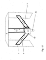
- the third variant shown in FIG. 11 has two opposing pairs of supports 5 with receptacle-side ends 7, which engage over the imaginary line J parallel to the bearing axis B of the base-part-side ends 10 of the respectively opposite pair of supports 5.
- the receiving-side ends 7 at a distance K parallel to the imaginary line J on.
- the distance K is the same for all variants of the second embodiment.
- the difference between the first and second variants is, in turn, that in FIG. 9, the distances I and K have the same magnitude, while the distance I in FIG. 10, but also in FIG. 11, is zero.
- the distance L between the base-part-side and the receiving-part-side end of each support of a support pair is zero.
- the receptacle-side ends 7 of the two opposite pairs of supports 5 intersect without impairing the action range of the respective other pair of supports 5.
- FIG. 12 shows a variant resulting from FIG. 9.
- a distance L which is measured perpendicular to the line J, is present between the base-part-side end 10 and the receiving part-side end 7 of the pair of supports 5D.
- FIG. 13 is a variant of the embodiment of FIG. 11, wherein here also a distance L between the base part end 10 and the receiving part end 7 of each support of the pair of supports 5 b is provided, which is measured perpendicular to the imaginary line J.
- the distance L can either be carried out in each case with the same amount or per pair of supports with different amounts, as already indicated above. The same applies to the distances U, U 1 and U 2 .
- a distance L between the receiving-side end and the base-part-side end of a support pair may also be possible on the third orthogonally arranged pair of supports, as shown in FIGS. 12 and 13.
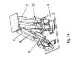
- the positioner shown as an example shown in FIG. 14 shows that the plate-shaped base part 3 is rectangular and that the receptacle 4 is also plate-shaped and rectangular.
- FIGS. 15 and 16 Two further embodiments of positioners (FIGS. 15 and 16) illustrate a fourth variant of the second exemplary embodiment. Notwithstanding here are the two supports 2 of the orthogonal to the two opposing pairs of columns 5 extending pair of supports 5 driven separately and each have their own drive and control unit 6 or at least one drive unit with associated encoder for detecting the drive position, which by a circle in Fig 13b is highlighted. As a result, the tilting or pivoting movement designated by arrow N can be realized.
- the arrangement of the support pairs 5 corresponds to the first variant according to FIG. 9 with offset base-part-side ends 10 and arrangement of the receiving-side ends 7 of the opposing pairs of supports 5 in alignment.
- Fig. 17 shows schematically a third embodiment of the device according to the invention, wherein the base part 3 has the shape of a cube. At three of five possible side surfaces of the cube each pair of supports 5 is arranged. On the sixth side surface of the cube, a holder 40 for the base part 3 is arranged.
- the receptacle 4 is formed in the form of a frame-shaped component, which extends spatially and is connected to the receiving-side ends of the three pairs of supports 5.
- base part-side ends and the receiving-side ends of the supports each have a pair of columns the same distance, which is not changeable.
Abstract
Description
Die vorliegende Erfindung betrifft eine Vorrichtung insbesondere zum Positionieren von wenigstens einem Objekt, mit längeneinstellbaren Stützen, mit einem Basisteil, mit einer Aufnahme für das Objekt, wobei die Stützen zwischen dem Basisteil und der Aufnahme angeordnet und dort jeweils gelenkig gelagert sind, und mit einem Antrieb und einer Steuerung zur Einstellung der Stützen, nach Patent
Solche Vorrichtungen zum Positionieren dienen dazu, ein Objekt in eine gewünschte Position zu verbringen und in dieser zu halten. Ein solches Objekt ist häufig ein Werkstück, das mit Hilfe der Vorrichtung in diese Position gebracht und dort festgehalten wird, so dass dann eine Bearbeitung, z. B. durch einen Roboter, erfolgen kann. Auch kann mit einer solchen Vorrichtung bei Bedarf das Objekt in weitere Positionen verfahren werden, in denen weitere Bearbeitungsschritte erfolgen können. Das Objekt kann auch ein Werkzeug sein, das zwecks Bearbeitung eines Werkstückes in unterschiedliche Positionen verbracht wird.Such devices for positioning serve to spend an object in a desired position and to hold in this. Such an object is often a workpiece, which is brought by means of the device in this position and held there, so that then a processing, for. B. by a robot can be done. Also, with such a device, if necessary, the object can be moved into further positions in which further processing steps can take place. The object may also be a tool that is moved to different positions for machining a workpiece.
Ein mögliches Einsatzgebiet einer Vorrichtung zum Positionieren von Objekten findet sich beispielsweise in der Automobilindustrie, wo in automatischen Fertigungslinien z.B. Karosserien etc. automatisch mittels Robotern bearbeitet werden.A possible field of use of a device for positioning objects can be found, for example, in the automotive industry, where, for example, bodies, etc., are automatically processed by robots in automatic production lines.
Die Stützen sind längenverstellbar und können im Raum verschwenkt werden. Die Bewegungen der Stützen werden durch Antriebe erzeugt, Steuereinrichtungen steuern den Bewegungsablauf und die Endkoordinaten der gewünschten Position.The supports are adjustable in length and can be swiveled in the room. The movements of the supports are generated by drives, control devices control the movement sequence and the end coordinates of the desired position.
So ist beispielsweise aus der
Aus der
Aufgabe der Erfindung ist es, die Vorrichtung der eingangs genannten Art weiter zu verbessern, wobei die Stabilität und Flexibilität für unterschiedliche Anwendungen erhöht und die Herstellungs- und Wartungskosten vermindert werden.The object of the invention is to further improve the device of the type mentioned, wherein the stability and flexibility for different applications increases and the manufacturing and maintenance costs are reduced.
Diese Aufgabe wird erfindungsgemäß durch die Merkmale des Patentanspruches 1 gelöst.This object is achieved by the features of
Danach ist eine Vorrichtung der in Rede stehenden Art derart weitergebildet, dass zumindest ein Stützenpaar aus zwei Stützen vorgesehen ist und dass sich die beiden Stützen des Stützenpaares parallel erstrecken, so dass sich die Form eines Parallelogramms ergibt.Thereafter, a device of the type in question is further developed such that at least one support pair of two supports is provided and that the two supports of the support pair extend parallel, so that the shape of a parallelogram results.
Erfindungsgemäß ist erkannt worden, dass die Stabilität verbessert werden kann und auch verschleißbedingte Wartungs- und Reparaturkosten vermieden werden können, wenn aus je zwei parallelen Stützen ein Stützenpaar gebildet wird, das die Form eines Parallelogramms aufweist. Auf diese Weise ist sichergestellt, dass einerseits jede Stütze einzeln Kräfte aufnimmt, andererseits aber auch jedes Stützenpaar als Kräftepaar betrachtet auch ein Moment aufnehmen kann.According to the invention it has been recognized that the stability can be improved and also wear-related maintenance and repair costs can be avoided if from each pair of parallel supports a pair of supports is formed, which has the shape of a parallelogram. In this way, it is ensured that on the one hand each support individually absorbs forces, but on the other hand considered each pair of supports as a couple of forces can also take a moment.
Für die Anordnung der Antriebs- und Steuereinheiten bestehen dabei folgende Möglichkeiten:
- Gemäß einer ersten Ausführungsform ist wenigstens eine Stütze wenigstens eines Stützenpaares mit einer Antriebs- und Steuereinrichtung zur Längeneinstellung ansteuerbar.
- According to a first embodiment, at least one support of at least one pair of supports with a drive and control device for length adjustment can be controlled.
Dabei kann gemäß einer weiteren vorteilhaften Ausgestaltung der Erfindung die Antriebseinrichtung der wenigstens einen Stütze räumlich zugeordnet und mit dieser bewegbar sein. Dabei können die Antriebs- und Steuereinrichtung eine räumliche Einheit miteinander bilden. Es besteht aber auch die Möglichkeit, dass die Steuereinrichtung räumlich von der Antriebseinrichtung getrennt angeordnet, gegebenenfalls in einem Schaltschrank untergebracht ist.In this case, according to a further advantageous embodiment of the invention, the drive means of spatially associated with the at least one support and be movable with this. In this case, the drive and control device form a spatial unit with each other. But there is also the possibility that the control device arranged spatially separated from the drive device, optionally housed in a control cabinet.
Die Stützen des Stützenpaares sind aufnahmeseitig und basisteilseitig beweglich d. h. gelenkig gelagert, damit die Einstellung des Objekts im Raum vorgenommen werden kann. Die Aufnahme selbst ist jedoch mit dem aufnahmeseitigen Ende des Stützenpaares fest verbunden, so dass die einzelnen Stützen um ihre Gelenkachse schwenken können, jedoch der räumliche Abstand der Gelenkachsen unveränderlich ist. Die Aufnahme kann damit in alle drei Richtungen des räumlichen Koordinatensystems bewegt werden, auch die winklige Lage der Aufnahme zum Baisteil ist entsprechend dem Bedarf einstellbar. Natürlich kann auch das Basisteil in seiner Lage verändert werden.The supports of the pair of supports are the receiving side and basisteilseitig movable d. H. hinged, so that the adjustment of the object can be made in the room. However, the receptacle itself is firmly connected to the receiving end of the pair of supports, so that the individual supports can pivot about their hinge axis, but the spatial distance of the joint axes is fixed. The recording can thus be moved in all three directions of the spatial coordinate system, and the angular position of the recording to Baisteil is adjustable according to the need. Of course, the base part can also be changed in its position.
Das Basisteil kann gemäß einer Ausführungsform als Plattform vorliegen, auf deren Oberseite das Stützenpaar angeordnet ist. Denkbar ist aber auch jede andere Form von Tragwerk, das ein räumlich definiertes Anordnen des Stützenpaares ermöglicht. Für eine höhere Stabilität im Hinblick auf zu positionierende Objekte unterschiedlicher Größe und Gewicht ist es von Vorteil, wenn sechs Stützen vorgesehen sind, da dadurch hohe Torsionsmomente in den Stützen vermieden werden und Zug- und Druckkräfte dominieren. Im Sinne der Minimierung der Herstellungskosten ist dann wiederum sinnvoll, diese sechs Stützen als drei Stützenpaare auszubilden.The base part may, according to one embodiment, be in the form of a platform on the upper side of which the pair of supports is arranged. It is also conceivable, however, any other form of structure that allows a spatially defined arrangement of the pair of supports. For greater stability with regard to objects of different sizes to be positioned and weight, it is advantageous if six supports are provided, as this high torsional moments are avoided in the supports and tensile and compressive forces dominate. In the sense of minimizing the production costs, it then makes sense again to design these six supports as three pairs of supports.
Eine im Hinblick auf eine kompakte Konstruktion vorteilhafte Ausführung der erfindungsgemäßen Vorrichtung mit drei Stützpaaren zeichnet sich dadurch aus, dass die basisteilseitigen Enden und die aufnahmeseitigen Enden der drei Stützenpaare jeweils im Sinne eines gedachten Dreiecks angeordnet sind. Im Hinblick auf eine hohe Stabilität ist es bevorzugt, den Abstand der aufnahmeseitigen Enden der drei Stützenpaare, geringer auszubilden als den Abstand der basisteilseitigen Enden der drei Stützenpaare, so dass das gedachte Dreieck im Bereich der Aufnahme kleiner ist als das gedachte Dreieck im Bereich des Basisteils.An embodiment of the device according to the invention with three support pairs, which is advantageous in terms of a compact design, is characterized in that the base part-side ends and the receptacle-side ends of the three support pairs are each arranged in the sense of an imaginary triangle. In view of a high stability, it is preferable to make the spacing of the receiving-side ends of the three pairs of supports smaller than the distance between the base-part-side ends of the three pairs of supports, so that the imaginary triangle in the region of the receptacle is smaller than the imaginary triangle in the region of the base part ,
Das gedachte Dreieck kann erfindungsgemäß gleichseitig sein.The imaginary triangle according to the invention may be equilateral.
Aber auch eine gleichschenklige Ausbildung des gedachten Dreiecks ist möglich. Diese gleichschenklige Ausgestaltung des Dreieckes führt zumindest in einer Raumrichtung zu einer noch kompakteren Bauweise, da es Winkel kleiner 60° aufweisen kann. Hierdurch kann der Platz- bzw. Raumbedarf optimiert werden. Dies ist beispielsweise bei der Anordnung der Vorrichtung zum Positionieren in einer Fertigungsstrasse interessant, da hier regelmäßig wenig Raum zwischen den Robotern, Förderbändern, Bauteilen usw. zur Verfügung steht.But an isosceles training of the imaginary triangle is possible. This isosceles configuration of the triangle leads at least in one spatial direction to an even more compact design, since it can have angles of less than 60 °. As a result, the space or space requirement can be optimized. This is interesting, for example, in the arrangement of the device for positioning in a production line, since there is little space available between the robots, conveyor belts, components, etc. on a regular basis.
Schließlich können das durch die basisteilseitigen Enden gebildete gedachte Dreieck und das durch die aufnahmeseitigen Enden gebildete gedachte Dreieck zueinander verdreht sein. In bestimmten Grenzen kann hierdurch die Grundfläche der Basisplattform zuzüglich der weiteren Bauteile minimiert werden. Außerdem kann eine Vorrichtung zum Positionieren flexibel auf unterschiedliche Anforderungen reagieren, indem der Verdrehwinkel zwischen dem aufnahmeseitigen gedachten Dreieck und basisteilseitigen gedachten Dreieck verändert wird. Je kleiner der Verdrehwinkel dabei ist, umso höher ist die Steifigkeit. Auch werden die Steifigkeit in horizontaler Richtung und die Biegesteifigkeit erhöht. Untersuchungen haben gezeigt, dass die Verteilung der Kräfte auf die sechs Stützen in der verdrehten Variante gleichmäßiger ist.Finally, the imaginary triangle formed by the base-part-side ends and the imaginary triangle formed by the receiving-side ends may be twisted with each other. Within certain limits, this makes it possible to minimize the base area of the base platform plus the other components. In addition, a positioning device can flexibly respond to different requirements by changing the twist angle between the receiving-side imaginary triangle and the base-part-side imaginary triangle. The smaller the twist angle, the higher the stiffness. Also, the rigidity in the horizontal direction and the flexural rigidity are increased. Investigations have shown that the distribution of forces on the six supports in the twisted variant is more uniform.
Eine weitere vorteilhafte Ausgestaltung der erfindungsgemäßen Vorrichtung mit mindestens drei Stützenpaaren geht dahin, dass die basisteilseitigen Enden zumindest zweier Stützenpaare sich gegenüberliegend auf einer ersten und zweiten Linie, die parallel zueinander verlaufen (Schwenkachsen B) und die basisteilseitigen Enden des dritten Stützenpaares auf einer dritten Linie liegen, die senkrecht zu der ersten und zweiten Linie verläuft und die die Schwenkachse (B) des dritten Stützenpaares bildet.A further advantageous embodiment of the device according to the invention with at least three pairs of supports is that the base part-side ends of at least two pairs of columns facing each other on a first and second line, the parallel to each other (pivot axes B) and the base part-side ends of the third pair of supports lie on a third line which is perpendicular to the first and second line and which forms the pivot axis (B) of the third pair of supports.
Bezüglich der gegenüberliegenden Stützenpaare können zwei Anordnungsvarianten hinsichtlich der basisteilseitigen Enden vorgesehen sein. Zum einen können die basisteilseitigen Enden der gegenüberliegenden Stützenpaare in Richtung ihrer parallelen Lagerachsen keinen Abstand zueinander aufweisen, so dass von einer diesbezüglichen Symmetrie gesprochen werden kann. Zum anderen könnten die basisteilseitigen Enden der gegenüberliegenden Stützenpaare in Richtung ihrer parallelen Lagerachsen auch zueinander beabstandet sein, so dass es zu einer versetzten Anordnung kommt. Beide Anordnungsvarianten eröffnen Spielraum für platzsparende und kostengünstige Lösungen für bestimmte Anwendungen, wenn auch die Stabilitätsanforderungen bei der Aufnahme von Drehmomenten ein wenig geringer sein müssen.With respect to the opposite pairs of supports, two arrangement variants can be provided with regard to the base part-side ends. On the one hand, the base-part-side ends of the opposing pairs of supports can have no distance from each other in the direction of their parallel bearing axes, so that it is possible to speak of a symmetry in this respect. On the other hand, the base-part-side ends of the opposite pairs of supports could also be spaced apart in the direction of their parallel bearing axes, so that a staggered arrangement occurs. Both arrangement variants provide scope for space-saving and cost-effective solutions for specific applications, although the stability requirements for the absorption of torques must be somewhat lower.
Dabei können die aufnahmeseitigen Enden der Stützenpaare - wie auch bei der Anordnung im Sinne eines gedachten Dreiecks - zur Erzielung einer hohen Stabilität einen geringeren Abstand zueinander aufweisen als die basisteilseitigen Enden der Stützenpaare. Dabei könnte bspw. die Anordnung der basisteilseitigen Enden der Stützenpaare durch deren aufnahmeseitigen Enden wiederholt werden, nur eben mit geringeren Abständen.In this case, the receiving ends of the support pairs - as well as in the arrangement in the sense of an imaginary triangle - to achieve a high stability a smaller distance from each other than the base part-side ends of the support pairs. In this case, for example, the arrangement of the base-part-side ends of the pairs of posts could be repeated by their receiving-side ends, but only at shorter intervals.
Nach einer bevorzugten Variante können die aufnahmeseitigen Enden der beiden gegenüberliegenden Stützenpaare auch auf einer gedachten Linie, parallel zu den Lagerachsen der basisteilseitigen Enden der gegenüberliegenden Stützenpaare, eine fluchtende Reihe ausbilden. Auf diese Weise gelingt es, besonders platzsparende Aufnahmen für Objekte bereitzustellen.According to a preferred variant, the receiving-side ends of the two opposite pairs of supports can also form an aligned line on an imaginary line parallel to the bearing axes of the base-part-side ends of the opposite pairs of supports. In this way, it is possible to provide particularly space-saving recordings for objects.
Diese Varianten sind den Ansprüchen 15 bis 18 zu entnehmen.These variants can be found in
Eine weitere vorteilhafte Ausgestaltung der Erfindung kann dahingehen, dass die aufnahmeseitigen Enden jedes der beiden gegenüberliegenden Stützenpaare zumindest teilweise eine gedachte, sich parallel zur Schwenkachse bzw. der ersten und zweiten Linie des basisteilseitigen Endes des jeweils gegenüberliegenden Stützenpaares erstreckende gedachte Linie übergreifen; dabei können die aufnahmeseitigen Enden der Stützen der gegenüberliegenden Stützenpaare beidseitig der gedachten vierten Linie liegen, wobei die Stützen der beiden Stützenpaare die gedachte vierte Linie überkreuzen.A further advantageous embodiment of the invention may be that the receiving ends of each of the two opposing pairs of supports at least partially overlap an imaginary, imaginary line extending parallel to the pivot axis or the first and second lines of the base-part-side end of the respectively opposite pair of supports; In this case, the receiving-side ends of the supports of the opposite pairs of supports can be on both sides of the imaginary fourth line, wherein the supports of the two pairs of supports cross the imaginary fourth line.
Die stabilitätserhöhende Variante mit den die gedachte vierte Linie kreuzenden Stützen und auch die Variante der fluchtenden Reihe aus aufnahmeseitigen Enden setzen voraus, dass ein gewisser Abstand zwischen den aufnahmeseitigen und basisteilseitigen Enden eines Stützenpaares der beiden gegenüberliegenden Stützenpaare parallel zu den Lagerachsen vorhanden sein muss. Ist dieser nicht vorhanden, so sind wenigstens die gegenüberliegenden Stützenpaare parallel zur Lagerachse zu beabstanden.The stability-increasing variant with the imaginary fourth line crossing supports and also the variant of the aligned row of receiving ends assume that a certain distance between the receiving side and basesteilseitigen ends of a pair of columns of the two opposite pairs of supports must be parallel to the bearing axes. If this is not present, then at least the opposite pair of supports are to be spaced parallel to the bearing axis.
Bei der in Rede stehenden vorteilhaften Ausführung der erfindungsgemäßen Vorrichtung mit zwei gegenüberliegenden Stützenpaaren und einem sich orthogonal hierzu erstreckenden Stützenpaar könnte das plattenförmige Basisteil rechteckig ausgebildet sein und ebenso die Aufnahme. In Betracht kommen auch kreis- oder ellipsenförmige oder auch beliebig geformte Aufnahmen als Werkstück- oder Werkzeugträger.In the presently advantageous embodiment of the device according to the invention with two opposing pairs of supports and a pair of orthogonal orthogonal extending support pair, the plate-shaped base member may be formed rectangular and also the recording. Also contemplated are circular or elliptical or arbitrarily shaped images as a workpiece or tool carrier.
Alle Stützenpaare der bisher geschilderten Ausführungen könnten kostengünstig mit nur je einer Antriebs- und Steuereinheit beziehungsweise mit mindestens einer Antriebseinheit und zugehörigem Geber zur Erfassung der Antriebsposition ausgerüstet sein. Will man jedoch ein bezüglich Lageveränderungen besonders flexibles Verhalten und eine homogene Lastverteilung erzielen, so sieht eine weitere Variante vor, zumindest zwei Stützen eines Stützenpaares separat anzutreiben. Vorzugsweise könnte es sich bei dem Stützenpaar mit den beiden separat angetriebenen Stützen um das sich orthogonal zu den beiden gegenüberliegenden Stützenpaaren erstreckende Stützenpaar handeln. Hierdurch könnte beispielsweise eine Schwenkbewegung der Aufnahme herbeigeführt werden, um Biegemomenten entgegenzuwirken, die vom Objekt verursacht werden, oder es könnte eine gesteuerte Schenkbewegung auf das Objekt als zusätzliche Bewegungsmöglichkeit ausgeübt werden. Innerhalb eines definierten Bewegungsbereiches wird eine weitgehende Richtungsunabhängigkeit hergestellt.All support pairs of the previously described embodiments could be cost-effectively equipped with only one drive and control unit or with at least one drive unit and associated encoder for detecting the drive position. However, if you want to achieve a particularly flexible behavior and a homogeneous load distribution with respect to changes in position, then another variant provides for driving at least two supports of a support pair separately. Preferably, the support pair with the two separately driven supports could be the pair of supports extending orthogonally to the two opposite pairs of supports. In this way, for example, a pivotal movement of the recording could be brought about to counteract bending moments caused by the object, or it could be exercised a controlled pivoting movement on the object as an additional possibility of movement. Within a defined range of motion, a largely directional independence is established.
Eine nächste vorteilhafte Ausführung der erfindungsgemäßen Vorrichtung befasst sich mit der Ausbildung des Basisteils in Form eines Körpers, an dessen Umfang das Stützenpaar oder mehrere Stützenpaare angeordnet ist bzw. sind. Dabei kann das Basisteil die Form eines Kubus aufweisen, wobei drei Seitenflächen des Kubus je ein Stützenpaar zugeordnet ist und diese sich näherungsweise orthogonal zueinander erstrecken. Hierdurch wird die Ausbildung der Aufnahme als räumliche Struktur, bspw. als rahmenförmiges Bauteil, möglich und damit eine Steigerung der Anwendbarkeit der erfindungsgemäßen Vorrichtung auf verschiedenste Erfordernisse räumlicher und objektgegebener Art. Das rahmenförmige Bauteil bietet gedankliche Anregungen im Bereich der Kraftfahrzeugtechnik, wo das Halten von Stoßstangen oder Prallstangen oftmals problematisch ist. Die Stützenpaare können auch mehr als drei Seiten des Kubus zugeordnet werden. Vorstellbar wären auch verschiedene Aufnahmen für bestimmte Stützpaare, verschiedene Funktionszuordnungen. Während an zwei Stützenpaaren Werkzeuge befestigt sind, können die übrigen Stützenpaare an ihrer gemeinsamen Aufnahme oder an ihren separaten Aufnahmen ein Bauteil halten.A next advantageous embodiment of the device according to the invention is concerned with the construction of the base part in the form of a body, on the circumference of which the pair of supports or a plurality of pairs of supports is / are arranged. In this case, the base part may have the shape of a cube, wherein three side surfaces of the cube are each associated with a pair of columns and these extend approximately orthogonal to each other. As a result, the formation of the receptacle as a spatial structure, for example. As a frame-shaped component, possible and thus an increase in the applicability of the device according to the invention to a variety of spatial and objektgegebener Art. The frame-shaped component provides ideas in the field of automotive technology, where the holding of bumpers or baffles often problematic is. The support pairs can also be assigned to more than three sides of the cube. Also conceivable would be different shots for certain support pairs, different function assignments. While tools are attached to two pairs of supports, the remaining pairs of supports can hold a component on their common receptacle or on their separate receptacles.
Diese und weitere vorteilhafte Ausgestaltungen und Verbesserungen der Erfindung ergeben sich aus den weiteren Unteransprüchen.These and other advantageous embodiments and improvements of the invention will become apparent from the other dependent claims.
Anhand der Zeichnung, in der einige Ausführungsbeispiele der Erfindung dargestellt sind, sollen die Erfindung sowie weitere vorteilhafte Ausgestaltungen und Verbesserungen und weitere Vorteile der Erfindung näher erläutert und beschrieben werden.Reference to the drawing, in which some embodiments of the invention are shown, the invention and further advantageous embodiments and improvements and further advantages of the invention will be explained and described in detail.
Es zeigen:
- Fig. 1
- ein Basis-Schema für ein Stützenpaar der erfindungsgemäße Vorrichtung,
- Fig. 2
- in perspektivischer Darstellung ein erstes Ausführungsbeispiel der erfindungsgemäßen Vorrichtung,
- Fig. 3
- in vergrößerter, perspektivischer Darstellung, ein Detail aus Fig. 2, betreffend die aufnahmeseitigen Enden eines Stützenpaares,
- Fig. 4
- eine Draufsicht auf die Vorrichtung gemäß Fig. 2,
- Fig. 5
- in schematischer Darstellung, eine erste Variante des ersten Ausführungsbeispiels der erfindungsgemäßen Vorrichtung,
- Fig. 6
- in schematischer Darstellung, ein Ausführungsbeispiel eines Positionierers entsprechend der in Fig. 5 gezeigten Variante,
- Fig. 7
- in schematischer Darstellung, eine zweite Variante des ersten Ausführungsbeispiels der erfindungsgemäßen Vorrichtung,
- Fig. 8
- in schematischer Darstellung, ein Ausführungsbeispiel gemäß der in Fig. 7 gezeigten Variante, entsprechend dem der Fig. 6,
- Fig. 9 bis 13
- einige Varianten der erfindungsgemäßen Vorrichtung, in schematischer Darstellung,
- Fig. 14
- in schematischer Darstellung, ein Ausführungsbeispiel eines Positionierers gemäß einer in den Fig. 9, 10, 11 gezeigten Variante,
- Fig. 15
- in schematischer Darstellung, ein weiteres Ausführungsbeispiel in Seitenansicht
- Fig. 16
- in schematischer Darstellung ein weiteres Ausführungsbeispiel in Vorderansicht und
- Fig. 17
- in schematischer, räumlicher Darstellung, ein weiteres Ausführungsbeispiel der erfindungsgemäßen Vorrichtung.
- Fig. 1
- a basic scheme for a prop pair of the device according to the invention,
- Fig. 2
- in a perspective view a first embodiment of the device according to the invention,
- Fig. 3
- in an enlarged, perspective view, a detail from FIG. 2, concerning the receiving ends of a pair of supports,
- Fig. 4
- a top view of the device according to FIG. 2,
- Fig. 5
- in a schematic representation, a first variant of the first embodiment of the device according to the invention,
- Fig. 6
- a schematic representation of an embodiment of a positioner according to the variant shown in Fig. 5,
- Fig. 7
- in a schematic representation, a second variant of the first embodiment of the device according to the invention,
- Fig. 8
- in a schematic representation, an embodiment according to the variant shown in Fig. 7, corresponding to that of Fig. 6,
- Fig. 9 to 13
- some variants of the device according to the invention, in a schematic representation,
- Fig. 14
- a schematic representation of an embodiment of a positioner according to a variant shown in FIGS. 9, 10, 11,
- Fig. 15
- in a schematic representation, another embodiment in side view
- Fig. 16
- in a schematic representation of another embodiment in front view and
- Fig. 17
- in a schematic, spatial representation, a further embodiment of the device according to the invention.
Die Figuren 1 bis 4, 6, 8, 12 bis 14 zeigen eine Vorrichtung zum Positionieren von Objekten 1 (siehe insbesondere Fig. 6, 8), mit längeneinstellbaren Stützen 2, mit einem Basisteil 3 und mit einer Aufnahme 4 für das Objekt 1. Die Stützen 2 sind zwischen dem Basisteil 3 und der Aufnahme 4 angeordnet und an diesen jeweils beweglich gelagert, wie weiter unten näher erläutert werden soll.FIGS. 1 to 4, 6, 8, 12 to 14 show an apparatus for positioning objects 1 (see in particular FIGS. 6, 8), with length-
Im Folgenden wird das in Fig. 2 links befindliche Stützenpaar näher betrachtet; die beiden anderen Stützenpaare 5a, 5b sind gleich aufgebaut.In the following, the support pair located on the left in FIG. 2 will be considered in greater detail; the two other pairs of
Erfindungsgemäß ist zumindest ein Stützenpaar 5 mit zwei parallel verlaufenden Stützen 2 vorgesehen. Das Stützenpaar 5 bildet, ebenso wie die anderen Stützenpaare, die Form eines Parallelogramms. Des weiteren ist erfindungsgemäß eine Antriebs- und Steuereinheit 6 vorgesehen; in der Antrieb und Steuerung zusammengefasst sind, siehe insbesondere Fig. 2. Wenigstens einer Antriebseinheit ist ein Geber zugeordnet, der der Erfassung der Antriebsposition dient.According to the invention, at least one
Am aufnahmeseitigen Ende 7 der Stütze 2 sind zwei Schwenklager 8, 9 vorgesehen (siehe Fig. 1, in der die Vorrichtung schematisch dargestellt ist), welche Schwenklager 8 mit der Aufnahme fest verbunden sind, was bedeutet, dass der Abstand der Schwenklager 8 unveränderlich ist. Beide Schwenklager 8 des Stützenpaares 5 weisen eine gemeinsame Schwenkachse A auf. Am basisteilseitigen Ende 10 jeder Stütze 2 sind weitere Schwenklager 11, 12, 13 vorgesehen, von denen die Schwenklager 11, 13 eine Schwenkachse B besitzen. In der in Fig. 1 dargestellten Stellung ist der Abstand der Schwenkachsen 8 zu den Schwenkachsen 11, 13 mit ΔL bezeichnet. Durch Veränderung der Längen der Stützen 2 lässt sich der Abstand ΔL variieren, so dass der Abstand der Schwenkachsen 8; 11, 13 voneinander auf ΔL1 vergrößert werden kann. Dies kann einmal dadurch erfolgen, dass bei quasi festgehaltenem Aufnahmeteil 4 das Basisteil 3 abgesenkt wird, so dass die Schwenkachsen 11, 13 auf der Linie C zu liegen kommen, und zum anderen dadurch, dass bei festgehaltenem Basisteil 3 das Aufnahmeteil 4 aus dem Abstand ΔL auf den Abstand ΔL1 angehoben wird. Das Absenken des Basisteils 3 kann beispielsweise dann erfolgen, wenn an dem Objekt, welches am Aufnahmeteil 4 angebracht ist, noch gewisse Arbeiten vorgenommen werden sollen, somit das Aufnahmeteil 4 noch feststehend im Raum verbleiben muss. Im Normalfall allerdings ist das Basisteil 3 feststehend, und das Aufnahmeteil 4 bewegt sich.At the receiving
Es wird Bezug genommen auf die Fig. 2.
Die in Fig. 2 dargestellte Vorrichtung 10 umfasst drei Stützenpaare 5, 5a, 5b, die im Wesentlichen gleich ausgebildet sind, wobei die Stützen 2 jedes Stützenpaares 5, 5a, 5b je eine Ebene aufspannen, die mit den jeweils anderen Ebenen ein Dreieck bildet. Die basisteilseitigen Enden der Stützen sind fest an U-förmigen ersten Lagerböcken 14, 15 befestigt und zwar auf der Außenseite jedes Quersteges 16, 17. An den Schenkeln 18, 19 jedes Lagerbockes 15, 16 (die Schenkel des Lagerbockes 15 sind verdeckt) sind je eine Drehachse 20 aufgenommen, die in einem Trägerbock 21 drehbar gelagert sind, der selbst wiederum über eine Achse 22 an fest mit dem Basisteil 3 verbundenen Stützböcken 23 gelagert ist. Die Achse 22 verläuft in der Ebene, die die Stützen des Stützenpaares 5 aufspannen, oder parallel dazu und darüber hinaus auch parallel zur Ebene des Basisteils. Wie aus der Fig. 2 insbesondere für das Stützenpaar 5b ersichtlich ist, sind zwei Stützböcke 23a und 23b vorgesehen, in denen die Achse 22 drehbar gelagert ist; über die Achse 22 ist der Trägerbock 21 drehbar gelagert, der sich zwischen den Stützböcken 23a, 23b befindet, und an diesem Trägerbock 21 sind die Lagerböcke 14, 15 schwenkbar gelagert, wobei die Schwenkachsen 20 oder Achsen 20 quer oder senkrecht zu der Achse 22 verlaufen. Zusammen können die Stützböcke 23a, 23b, der Trägerbock 21 und die Lagerböcke 14, 15 mit den Schwenkachsen 20 und 22 ein kombiniertes Universalgelenk für ein Stützenpaar 5, 5a, 5b ausbilden. Alternativ können zur Ausbildung der gewünschten Beweglichkeit auch zwei einzelne Universalgelenke eingesetzt werden, deren Schwenkachsen dann kinematisch äquivalent zu den Schwenkachsen 20 und 22 ausgerichtet sein müssen. Für jedes der drei Stützenpaare 5, 5a, 5b ist lediglich eine Antriebs- und Steuereinheit 6 oder mindestens eine Antriebseinheit mit zugeordnetem Geber zur Erfassung der Antriebsposition 6 vorgesehen, wobei die beiden Stützen 2 jedes Stützenpaares 5, 5a und 5b mit der Antriebs- und Steuereinheit synchronisiert sind. Die Parallelität der beiden Stützen 2 aller Stützenpaare 5, 5a und 5b wird dadurch herbeigeführt, dass der Abstand der basisteilseitigen Enden 10 und der aufnahmeseitigen Enden 7 der beiden Stützen 2 aller Stützenpaare jeweils gleich ist.Reference is made to FIG. 2.
The
Die Verbindung der Stützen 2 jedes Stützenpaares 5, 5a und 5b mit dem Aufnahmeteil 4 erfolgt über jeweils ein Universalgelenk 24, welches an Hand der Fig. 3 näher erläutert wird. Das Universalgelenk 24 umfasst ein erstes Gelenkteil 25, welches mit dem ausfahrbaren Abschnitt 26 jeder Stütze fest verbunden ist. An distal sich gegenüberliegenden Mantellinien des ersten Gelenkteils 25 sind Laschen 27, 28 angeordnet, hier angeformt, die eine Schwenkachse 29 aufnehmen, um die ein sich zwischen den Laschen 27, 28 befindliches Kardangelenkkreuz 30 drehen kann. An dem Aufnahmeteil 4 ist ein zweites Gelenkteil 31 befestigt, welches den Laschen 27, 28 entsprechende Laschen 32 aufweist, welche zum ersten Gelenkteil 25 hin vorspringen, d. h. also vom Aufnahmeteil 4 weg. Das Kardangelenkkreuz 30 befindet sich auch zwischen den beiden Laschen 32 und ist an diesen über eine Achse 33 schwenkbar gelagert, wobei die Achsen 29 und 33 senkrecht zueinander verlaufen und sich entweder in einem Punkt schneiden können oder sich in einem definierten Abstand zueinander schneiden. Alternativ können beide Universalgelenke zu einem kombinierten Universalgelenk zusammengefasst werden, in dem die beiden Kardangelenkkreuze auf ihrer gemeinsamen Schwenkachse 33 steif miteinander gekoppelt werden oder beide Kardangelenkkreuze 30 in einem Bauteil zusammengefasst werden, ähnlich dem Trägerbock 21. Damit kann sich die Stütze 2 in Doppelpfeilrichtung P2 um die Achse 29 und zusammen mit dem Kardangelenkkreuz 30 um die senkrecht dazu verlaufende Achse 33 P3 senkrecht zu der durch die beiden Stützen 2 aufgespannten Ebene, d. h. auf diese zu und von dieser weg, verschwenken. Das Basisteil 3 (Fig. 2), ist im Sinne einer sechseckigen Plattform ausgebildet; die Aufnahme 4 ist als kreisförmige Plattform mit Montageöffnungen 34 ausgebildet.The connection of the
Am basisteilseitigen Ende der Stützen 2 bzw. des Stützenpaares 5a ist pro Stütze 2, wie oben dargestellt, ein Schwenklager 15, 16 vorgesehen, deren Abstand dem Abstand der beiden Universalgelenke 24 am aufnahmeseitigen Ende 7 der Stützen 2 entspricht. Die Schwenklager 15, 16 sind mit ihren Lagerachsen so gelagert, dass sie senkrecht zur Schwenkachse 22 verschwenkbar sind. Die Schwenkachse 22 liegt dabei tangential an einem gedachten Kreis an, der sich um den Mittelpunkt M des Basisteils 3 erstreckt und dessen Radius durch die Schwenkachse 22 bestimmt ist. An dem Trägerbock 21 ist ein Träger 35 angebracht, auf dem die Antriebs- und Steuereinheit 6 befestigt ist, so dass sich die Antriebs- und Steuereinheit 6 zusammen mit dem Trägerbock 21 verschwenken kann.At the base part-side end of the
Aus Fig. 4 ist ersichtlich, dass die basisteilseitigen Enden 10 und die aufnahmeseitigen Enden 7 der drei Stützenpaare 5 jeweils im Sinne eines gedachten, insbesondere in Fig. 4 gestrichelt dargestellten Dreiecks DA und DB angeordnet sind.It can be seen from FIG. 4 that the base-part-side ends 10 and the receiving-side ends 7 of the three pairs of
Weiter oben ist dargestellt, dass die Stützenpaare jeweils einer Ebene aufspannen, die jeweils ein Dreieck miteinander bilden. Dabei ist das Dreieck an den basisteilseitigen Enden der Stützenpaare 5, 5a, 5b größer als das Dreieck, das die Ebenen am aufnahmeteilseitigen Ende der Stützenpaare 5, 5a und 5b miteinander bilden. Bei der Darstellung und Erläuterung zu Fig. 4, was auch für die folgenden Darstellung gilt, sind die gedachten Dreiecke dadurch gebildet, dass die Stützenpaare jeweils als Einheit aufgefasst werden, die einen gemeinsamen Mittelpunkt im Bereich der basisteilseitigen Enden und der aufnahmeseitigen Enden besitzen; diese Mittelpunkte bilden dann jeweils das Dreieck DA, DB, welche Dreiecke gegenüber den durch die Ebenen der Stützenpaare gebildeten Dreiecken um 60° verschwenkt sind. Der Abstand E der benachbarten aufnahmeseitigen Enden 7 der drei Stützenpaare 5 ist geringer ist als der Abstand F der benachbarten basisteilseitigen Enden 10 der drei Stützenpaare 5. Anders ausgedrückt: Die Seitenlänge E des aufnahmeseitigen Dreiecks DA ist kleiner als die Seitenlänge F des basisteilseitigen Dreiecks. Die Aufnahme 4 ist flächenmäßig kleiner als das Basisteil 3. Die Dreiecke DA und DB sowie die Abstände E und F sind auch den Fig. 5 und 7 betreffend die zweite und dritte Variante des ersten Ausführungsbeispiels zu entnehmen. Die Flächenverhältnisse der Aufnahme 4 zum Basisteil 3 sind in den Fig. 6 und 8 dargestellt. Dort sind in den Beispielpositionen auch die unterschiedlichen Raumverhältnissen gerecht werdenden Geometrien der Aufnahme 4 und des Basisteils 3 ersichtlich sowie das Objekt 1 in Form eines Werkzeuges auf der als Plattform ausgebildeten Aufnahme 4.It is shown above that the pairs of supports each span a plane which each form a triangle with one another. In this case, the triangle at the base part-side ends of the support pairs 5, 5a, 5b is larger than the triangle forming the planes at the receiving part-side end of the support pairs 5, 5a and 5b with each other. In the illustration and explanation of Figure 4, which also applies to the following illustration, the imaginary triangles are formed by the fact that the pairs of supports are each considered as a unit having a common center in the region of the base part-side ends and the receiving-side ends; these centers then each form the triangle DA, DB, which triangles are pivoted by 60 ° with respect to the triangles formed by the planes of the pairs of columns. The distance E of the adjacent receiving-side ends 7 of the three pairs of
Die erste (Fig. 4) und dritte Variante (Fig. 7) des ersten Ausführungsbeispiels zeigen die Ausbildung jeweils eines gleichseitigen gedachten Dreiecks DA, DB und die entsprechende Anordnung der drei Stützenpaare 5, siehe Fig. 7. Bei der zweiten Variante sind die beiden gedachten gedachte Dreiecke DA, DB gleichschenklig ausgebildet, siehe Fig. 5.The first (Fig. 4) and third variant (Fig. 7) of the first embodiment show the formation of an equilateral imaginary triangle DA, DB and the corresponding arrangement of the three pairs of
Die dritte Variante unterscheidet sich von der ersten Variante des ersten Ausführungsbeispiels dadurch, dass das durch die basisteilseitigen Enden 10 gebildete gedachte Dreieck DB und das durch die aufnahmeseitigen Enden 7 gebildete gedachte Dreieck DA zueinander verdreht sind, wie aus der Fig. 7 zu entnehmen. Mit a ist der Verdrehwinkel zwischen dem aufnahmeseitigen Ende 7 und dem basisteilseitigen Ende 10 bezeichnet. Die nicht näher bezeichneten Eckpunkte der gedachten Dreiecke in den Fig. 4, 5, 7 sollen die Mitte zwischen den konstant beabstandeten Stützen 2 jedes Stützenpaares 5 sowohl an dessen aufnahmeseitigen Ende 7 als auch an dessen basisteilseitigen Ende 10 verdeutlichen.The third variant differs from the first variant of the first embodiment in that the imaginary triangle DB formed by the base-part-side ends 10 and the imaginary triangle DA formed by the receiving-side ends 7 are twisted relative to each other, as shown in FIG. With a, the angle of rotation between the receiving
Bei dem in den Fig. 9 bis 11, 10a und 11a gezeigten zweiten Ausführungsbeispiel sind ebenfalls drei Stützenpaare 5 vorgesehen, jedoch ist die Anordnung der drei Stützenpaare zueinander anders als beim ersten Ausführungsbeispiel. Die basisteilseitigen Enden 10 zweier Stützenpaare 5 sind gegenüberliegend angeordnet. Das dritte Stützenpaar 5D erstreckt sich orthogonal zu den beiden gegenüberliegenden zwei Stützenpaaren 5. Die in Fig. 9 gezeigte Variante verdeutlicht bei 1 den Abstand I der beiden basisteilseitigen Enden 10 der gegenüberliegenden Stützenpaare 5 in Richtung ihrer parallelen Schwenkachsen B. Bei den in den Fig. 10 und 11 gezeigten Varianten ist kein Abstand I vorhanden, da dort keine Versetzung der basisteilseitigen Enden 10 stattfindet, sondern eine symmetrische Anordnung zu einer gedachten Linie J vorliegt.In the second embodiment shown in Figs. 9 to 11, 10a and 11a, three pairs of
Auch bei dem zweiten Ausführungsbeispiel kann das aufnahmeseitige Ende 7 des einen Stützenpaares 5 einen geringeren Abstand F zum anderen aufnahmeseitigen Ende des nächsten Stützenpaares 5 aufweisen als die die entsprechenden basisteilseitigen Enden 10 der Stützenpaare 5 mit dem Abstand E, was aber aus Übersichtlichkeitsgründen nicht dargestellt ist.Also in the second embodiment, the receiving-
Gemäß den in den Fig. 9 und 10 gezeigten ersten und zweiten Varianten des zweiten Ausführungsbeispiels bilden die aufnahmeseitigen Enden 7 der beiden gegenüberliegenden Stützenpaare 5 auf der gedachten Linie J, parallel zu den Schwenkachsen B der basisteilseitigen Enden 10 der gegenüberliegenden Stützenpaare 5 eine fluchtende Reihe aus.According to the first and second variants of the second embodiment shown in FIGS. 9 and 10, the receiving-side ends 7 of the two opposing pairs of
Bei der Ausführung gemäß Fig. 9 verlaufen die Stützen der Stützpaare 5, die sich gegenüberliegen, parallel zueinander und senkrecht zu der gedachten Linie J; die Stützen des Stützpaares 5D verlaufen dann parallel zur Linie J.In the embodiment according to FIG. 9, the supports of the support pairs 5, which lie opposite one another, run parallel to one another and perpendicular to the imaginary line J; the supports of the
Bei der Ausführung gemäß der Fig. 10 verlaufen die Stützen der sich gegenüberliegenden Stützpaare 5 unter einem Winkel zu der gedachten Linie J, so dass die basisteilseitigen Enden 10 zu den aufnahmeteilseitigen Enden 7 einen Abstand L1 zwischen sich einnehmen, gemessen in Richtung der gedachten Linie J. Die aufnahmeteilseitigen Enden 7, die einander auf der Linie J benachbart liegen, besitzen einen Abstand K.In the embodiment according to FIG. 10, the supports of the opposite support pairs 5 extend at an angle to the imaginary line J, so that the base part-side ends 10 to the receiving part-side ends 7 occupy a distance L 1 between them, measured in the direction of the imaginary line J. The receiving part-side ends 7, which are adjacent to each other on the line J, have a distance K.
Die in Fig. 11 dargestellte dritte Variante verfügt über zwei gegenüberliegende Stützenpaare 5 mit aufnahmeseitige Enden 7, die die gedachte Linie J parallel zur Lagerachse B der basisteilseitigen Enden 10 des jeweils gegenüberliegenden Stützenpaares 5 übergreifen. Außerdem weisen die aufnahmeseitige Enden 7 einen Abstand K parallel zur gedachten Linie J auf. Der Abstand K ist bei allen Varianten des zweiten Ausführungsbeispiels gleich. Der Unterschied zwischen erster und zweiter Variante besteht wiederum darin, dass in Fig. 9 die Abstände I und K den gleichen Betrag aufweisen, während der Abstand I in Fig. 10, aber auch in Fig. 11 Null ist. Bei dem Beispiel gemäß Fig. 9 ist der Abstand L zwischen dem basisteilseitigen und dem aufnahmeteilseitigen Ende je der Stütze eines Stützenpaares Null.The third variant shown in FIG. 11 has two opposing pairs of
Bei der dritten Variante des zweiten Ausführungsbeispiels kreuzen sich die aufnahmeseitigen Enden 7 der beiden gegenüberliegenden Stützenpaare 5, ohne den Aktionsbereich des jeweils anderen Stützenpaares 5 zu beeinträchtigen.In the third variant of the second exemplary embodiment, the receptacle-side ends 7 of the two opposite pairs of
Die Fig. 12 zeigt eine aus der Fig. 9 entstandene Variante. Hierbei ist zwischen dem basisteilseitigen Ende 10 und dem aufnahmeteilseitigen Ende 7 des Stützenpaares 5D ein Abstand L vorhanden, der senkrecht zur Linie J gemessen ist.FIG. 12 shows a variant resulting from FIG. 9. In this case, a distance L, which is measured perpendicular to the line J, is present between the base-part-
Die Ausführung gemäß Fig. 13 ist eine Variante zur Ausführung gemäß Fig. 11, wobei hier ebenfalls ein Abstand L zwischen dem basisteilseitigen Ende 10 und dem aufnahmeteilseitigen Ende 7 jeder Stütze des Stützenpaares 5b vorgesehen ist, der senkrecht zu der gedachten Linie J gemessen ist.The embodiment of FIG. 13 is a variant of the embodiment of FIG. 11, wherein here also a distance L between the
Bei den Ausführungen der Figuren 9 bis 13 sind im Wesentlichen die gleichen Bezugsziffern verwendet worden, ebenso wie für alle Abstände die Bezeichnung L, wobei die Abstände L bei den einzelnen Varianten der Figuren 9 bis 13 durchaus unterschiedlich sein können, was auch für die Bemessung der Abstände K gilt. Nachzutragen ist noch, dass die Abstände der Schwenkachsen B zu der gedachten Linie J in der Fig. 9 mit U, in der Fig. 10 und 11 mit U1 und U2 bezeichnet ist, um anzudeuten, dass gegebenenfalls diese Abstände auch variieren und unterschiedlich sein können.In the embodiments of Figures 9 to 13, substantially the same reference numerals have been used, as well as for all distances the designation L, wherein the distances L in the individual variants of Figures 9 to 13 may well be different, which also for the design of the Distances K applies. It should also be added that the distances of the pivot axes B to the imaginary line J in FIG. 9 are indicated by U, and in FIG. 10 and 11 by U 1 and U 2 , in order to indicate that these distances may also vary and differ could be.
Um verschiedene Lastaufnahmen zu ermöglichen, werden verschiedene Positionen eingenommen. Dabei kann - wie in der ersten Variante gezeigt - innerhalb eines Stützenpaares eine gegenüberliegende Anordnung oder, wie in der zweiten und dritten Variante gezeigt - eine versetzt gegenüberliegende Anordnung des aufnahmeseitigen Endes 5 zum basisteilseitigen Ende 10 erfolgen. Bei der zweiten und dritten Variante des zweiten Ausführungsbeispieles ist daher ein Abstand L zwischen dem aufnahmeseitigen Ende 7 und dem basisteilseitigen Enden 10 eines Stützenpaares 5 existent, bei der erste Variante des zweiten Ausführungsbeispieles dagegen nicht. Auf den gegenüberliegenden Stützenpaaren kann der Abstand L entweder jeweils mit gleichem Betrag oder auch je Stützenpaar mit unterschiedlichem Betrag ausgeführt sein, wie oben schon angedeutet. Das gleichen gilt auch für die Abstände U, U1 und U2. Desweiteren kann auch an dem dritten orthogonal angeordneten Stützenpaar ein Abstand L zwischen dem aufnahmeseitigen Ende und dem basisteilseitigen Ende eines Stützenpaaren möglich sein, wie in der Fig. 12 und 13 dargestellt.In order to enable different load recordings, different positions are taken. It can - as shown in the first variant - within a pair of supports an opposite arrangement or, as shown in the second and third variants - a staggered opposite arrangement of the receiving
Der beispielhaft gezeigte Positionierer gemäß Fig. 14 zeigt, dass das plattenförmige Basisteil 3 rechteckig ausgebildet ist und dass die Aufnahme 4 ebenfalls plattenförmig und rechteckig ausgebildet ist.The positioner shown as an example shown in FIG. 14 shows that the plate-shaped
Zwei weitere Ausgestaltungen von Positionierern (Figuren 15 und 16) veranschaulichen eine vierte Variante des zweiten Ausführungsbeispiels. Abweichend sind hier die beiden Stützen 2 des sich orthogonal zu den beiden gegenüberliegenden Stützenpaaren 5 erstreckenden Stützenpaares 5 separat angetrieben und weisen jeweils eine eigene Antriebs- und Steuereinheit 6 oder mindestens eine Antriebseinheit mit zugeordnetem Geber zur Erfassung der Antriebsposition auf, die durch einen Kreis in Fig. 13b hervorgehoben ist. Hierdurch kann die mit Pfeil N bezeichnete Kipp- oder Schwenkbewegung realisiert werden. Die Anordnung der Stützenpaare 5 entspricht der ersten Variante gemäß Fig. 9 mit versetzten basisteilseitigen Enden 10 und Anordnung der aufnahmeseitigen Enden 7 der gegenüberliegenden Stützenpaare 5 in fluchtender Reihe.Two further embodiments of positioners (FIGS. 15 and 16) illustrate a fourth variant of the second exemplary embodiment. Notwithstanding here are the two
Schließlich zeigt Fig. 17 schematisch ein drittes Ausführungsbeispiel der erfindungsgemäßen Vorrichtung, wobei das Basisteil 3 die Form eines Kubus aufweist. An drei von fünf möglichen Seitenflächen des Kubus ist jeweils ein Stützenpaar 5 angeordnet. An der sechsten Seitenfläche des Kubus ist eine Halterung 40 für das Basisteil 3 angeordnet. Die Aufnahme 4 ist in Form eines rahmenförmigen Bauteiles ausgebildet, das sich räumlich erstreckt und mit den aufnahmeseitigen Enden der drei Stützenpaare 5 verbunden ist.Finally, Fig. 17 shows schematically a third embodiment of the device according to the invention, wherein the
Abschließend sei darauf hingewiesen, dass die erfindungsgemäße Lehre nicht auf die voranstehend erörterten Ausführungsbeispiele eingeschränkt ist. Vielmehr sind die unterschiedlichsten Ausbildungen der Basisteile und Aufnahmen in platzsparenden Polygonformen oder unterschiedlichen Raumdimensionen möglich. Auch im Hinblick auf die Synchronisation der Stützen 2, die Kraftübertragung von der Antriebs- und Steuereinheit 6 auf die Stützen 2 stehen prinzipiell viele Möglichkeiten offen.Finally, it should be noted that the teaching of the invention is not limited to the embodiments discussed above. Rather, the most varied designs of the base parts and recordings in space-saving polygon shapes or different spatial dimensions are possible. With regard to the synchronization of the
Es soll nochmals festgehalten sein, dass die basisteilseitigen Enden und die aufnahmeseitigen Enden der Stützen jeweils eines Stützenpaares den gleichen Abstand besitzen, der nicht veränderbar ist.It should be noted again that the base part-side ends and the receiving-side ends of the supports each have a pair of columns the same distance, which is not changeable.
- 11
- Objektobject
- 22
- Stützesupport
- 33
- Basisteilbase
- 44
- Aufnahmeadmission
- 55
- Stützenpaarpair of supports
- 66
- Antriebs- und SteuereinheitDrive and control unit
- 77
- aufnahmeseitiges Enderecording end
- 88th
- Schwenklagerpivot bearing
- 99
- Schwenklagerpivot bearing
- 1010
- basisteiliges Endebase-part end
- 1111
- Schwenklagerpivot bearing
- 1212
- Schwenklagerpivot bearing
- 1313
- Schwenklagerpivot bearing
- 1414
- Universalgelenkuniversal joint
- 1515
- Verbindungsbauteilconnecting member
- 1616
- Montageöffnungmounting hole
- 1717
- Verbindungsbauteilconnecting member
- 1818
- Tragteilsupporting part
- 1919
- Halterungbracket
- Δl.DELTA.l
- Abstand, LängenänderungDistance, length change
- x,y,zx, y, z
- räumliche Dimensionenspatial dimensions
- AA
- Schwenkachseswivel axis
- BB
- Schwenkachseswivel axis
- CC
- Schwenkachse - geänderte PositionSwivel axis - changed position
- DATHERE
- gedachtes Dreieckthought triangle
- DBDB
- gedachtes Dreieckthought triangle
- Ee
- Abstanddistance
- FF
- Abstanddistance
- GG
- Gelenkachsejoint axis
- HH
- Gelenkachsejoint axis
- aa
- Verdrehwinkelangle of twist
- II
- Abstanddistance
- JJ
- gedachte Linieimaginary line
- KK
- Abstanddistance
- LL
- Abstanddistance
- MM
- MittelpunktFocus
- NN
- Pfeilarrow
Claims (32)
mit längeneinstellbaren Stützen (2),
mit einem Basisteil (3),
mit einer Aufnahme (4) für das Objekt (1),
wobei die Stützen (2) zwischen dem Basisteil (3) und der Aufnahme (4) angeordnet und dort jeweils beweglich gelagert sind, und
mit Antrieb und Steuerung zur Einstellung der Stützen (2), nach Patent DE 10 2006 011 823.5,
dadurch gekennzeichnet,
dass zumindest ein Stützenpaar (5) aus zwei Stützen (2) gebildet ist, die parallel ineinander verlaufen und miteinander die Form eines Parallelogramms bilden.Device, in particular for positioning objects (1),
with adjustable-length supports (2),
with a base part (3),
with a receptacle (4) for the object (1),
wherein the supports (2) between the base part (3) and the receptacle (4) are arranged and mounted there in each case movable, and
with drive and control for adjusting the supports (2), according to patent DE 10 2006 011 823.5,
characterized,
in that at least one support pair (5) is formed from two supports (2) which run parallel to one another and together form the shape of a parallelogram.
Applications Claiming Priority (1)
| Application Number | Priority Date | Filing Date | Title |
|---|---|---|---|
| DE102006046758A DE102006046758A1 (en) | 2006-09-29 | 2006-09-29 | Arrangement, especially for positioning objects, has at least one pair of supports made up of two supports that run parallel one inside the other and together form parallelogram |
Publications (1)
| Publication Number | Publication Date |
|---|---|
| EP1930132A1 true EP1930132A1 (en) | 2008-06-11 |
Family
ID=39134445
Family Applications (1)
| Application Number | Title | Priority Date | Filing Date |
|---|---|---|---|
| EP07017249A Ceased EP1930132A1 (en) | 2006-09-29 | 2007-09-04 | Device, in particular for positioning objects |
Country Status (5)
| Country | Link |
|---|---|
| US (1) | US20080078266A1 (en) |
| EP (1) | EP1930132A1 (en) |
| CN (1) | CN101195210A (en) |
| CA (1) | CA2604830A1 (en) |
| DE (1) | DE102006046758A1 (en) |
Families Citing this family (9)
| Publication number | Priority date | Publication date | Assignee | Title |
|---|---|---|---|---|
| DE102006011823A1 (en) * | 2006-03-13 | 2007-09-20 | Abb Patent Gmbh | positioning |
| US9545697B2 (en) * | 2009-04-06 | 2017-01-17 | The Boeing Company | Automated hole generation |
| KR20110025256A (en) * | 2009-09-04 | 2011-03-10 | (주)유스텍 | Location pin |
| CN104308775B (en) * | 2014-10-20 | 2016-05-18 | 中科院南京天文仪器有限公司 | A kind of heavy instrument accurate positioning device |
| DE112016002211T5 (en) * | 2015-05-16 | 2018-05-24 | Abb Schweiz Ag | Additional rotation axis for a robot |
| DE102017129598A1 (en) * | 2017-12-12 | 2019-06-13 | Gerhard Schubert Gmbh | Delta robot and robotic street equipped with it |
| WO2020081111A1 (en) * | 2018-10-19 | 2020-04-23 | Cowley Daniel J | Mechanism combining articulation and side-shift |
| ES2950572T3 (en) * | 2018-12-20 | 2023-10-11 | Fundacion Tecnalia Res & Innovation | Workpiece support system |
| CN110722477B (en) * | 2019-10-17 | 2021-04-27 | 成都飞机工业(集团)有限责任公司 | Four-bar linkage mechanism for large-scale detachable positioner of assembly fixture |
Citations (5)
| Publication number | Priority date | Publication date | Assignee | Title |
|---|---|---|---|---|
| US5272805A (en) | 1991-04-01 | 1993-12-28 | Fanuc Robotics North America, Inc. | System for the flexible assembly of assemblies |
| US5987726A (en) | 1996-03-11 | 1999-11-23 | Fanuc Robotics North America, Inc. | Programmable positioner for the stress-free assembly of components |
| US6041500A (en) | 1998-01-23 | 2000-03-28 | Giddings & Lewis, Inc. | Automatic assembly machine and method utilizing six-axis positioning device |
| US6581437B2 (en) | 2000-05-12 | 2003-06-24 | Alberta Research Council Inc. | Motion platform and method of use |
| WO2007104446A1 (en) | 2006-03-13 | 2007-09-20 | Abb Ag | Positioning device |
Family Cites Families (42)
| Publication number | Priority date | Publication date | Assignee | Title |
|---|---|---|---|---|
| US4666362A (en) * | 1985-05-07 | 1987-05-19 | Massachusetts Institute Of Technology | Parallel link manipulators |
| FR2628670B1 (en) * | 1988-03-21 | 1990-08-17 | Inst Nat Rech Inf Automat | ARTICULATED DEVICE, IN PARTICULAR FOR USE IN THE FIELD OF ROBOTICS |
| US5401128A (en) * | 1991-08-26 | 1995-03-28 | Ingersoll Milling Machine Company | Octahedral machine with a hexapodal triangular servostrut section |
| US5279176A (en) * | 1992-07-20 | 1994-01-18 | The United States Of America As Represented By The Administrator Of The National Aeronautics And Space Administration | Six-degree-of-freedom parallel "minimanipulator" with three inextensible limbs |
| US5813287A (en) * | 1994-03-02 | 1998-09-29 | Renishaw Plc | Coordinate positioning machine |
| JP2560262B2 (en) * | 1994-11-09 | 1996-12-04 | 工業技術院長 | Two-finger micro hand mechanism |
| JP3640087B2 (en) * | 1994-11-29 | 2005-04-20 | 豊田工機株式会社 | Machine Tools |
| US5656905A (en) * | 1995-04-03 | 1997-08-12 | Tsai; Lung-Wen | Multi-degree-of-freedom mechanisms for machine tools and the like |
| US5740699A (en) * | 1995-04-06 | 1998-04-21 | Spar Aerospace Limited | Wrist joint which is longitudinally extendible |
| DE59603026D1 (en) * | 1995-12-20 | 1999-10-14 | Wiegand Alexander Konrad | DEVICE FOR THE SPACIOUS CONTROLLED MOVEMENT OF A BODY IN THREE TO SIX DEGREES OF FREEDOM |
| DE19611130A1 (en) * | 1996-03-21 | 1997-09-25 | Vdw Verein Deutscher Werkzeugm | Machine tool or toolholder platform orientation system |
| DE19614641B4 (en) * | 1996-04-13 | 2004-03-25 | Wurst, Karl-Heinz, Dr.-Ing. | Device for machining and assembling workpieces |
| US5787758A (en) * | 1996-09-03 | 1998-08-04 | Sheldon/Van Someren, Inc. | Three-axis machine for rapid and rigid manipulation of components |
| JPH10118966A (en) * | 1996-10-21 | 1998-05-12 | Toyoda Mach Works Ltd | Parallel robot |
| FR2779086B1 (en) * | 1998-04-27 | 2000-06-30 | Const Mecaniques Des Vosges Ma | COMPENSATOR SYSTEM FOR HEXAPODE |
| US6240799B1 (en) * | 1998-05-26 | 2001-06-05 | Hexel Corporation | Triangular gimbal |
| JP2000130536A (en) * | 1998-10-27 | 2000-05-12 | Fanuc Ltd | Parallel link mechanism |
| US6497548B1 (en) * | 1999-08-05 | 2002-12-24 | Shambhu Nath Roy | Parallel kinematics mechanism with a concentric sperical joint |
| KR100334902B1 (en) * | 1999-12-06 | 2002-05-04 | 윤덕용 | 6 Degree-of-freedom Parallel Mechanism for Micro-positioning Task |
| CN1092092C (en) * | 2000-04-21 | 2002-10-09 | 清华大学 | Spatial triaxial parallel machine tool structure with two-dimensional shift and one-dimensional rotation |
| US6418811B1 (en) * | 2000-05-26 | 2002-07-16 | Ross-Hime Designs, Inc. | Robotic manipulator |
| FR2825445B1 (en) * | 2001-05-31 | 2004-02-13 | Innovation Technologie Conseil | METHOD OF ORIENTATION OF A HEXAPOD TURRET |
| JP2005536703A (en) * | 2001-07-05 | 2005-12-02 | マイクロデクステラティー・システムズ・インコーポレーテッド | Parallel manipulator |
| US6671975B2 (en) * | 2001-12-10 | 2004-01-06 | C. William Hennessey | Parallel kinematic micromanipulator |
| FR2835068B1 (en) * | 2002-01-22 | 2004-09-03 | Commissariat Energie Atomique | CONTROLLER HAVING THREE PARALLEL BRANCHES |
| CA2492147A1 (en) * | 2002-07-09 | 2004-01-15 | Amir Khajepour | Light weight parallel manipulators using active/passive cables |
| TW546595B (en) * | 2002-07-23 | 2003-08-11 | Internet Motion Navigator Corp | Six-axis translation-type dynamic simulation device |
| US6808344B2 (en) * | 2002-12-27 | 2004-10-26 | Jeng-Shyong Chen | Multi-axis cartesian guided parallel kinematic machine |
| SE0302610L (en) * | 2003-10-02 | 2005-03-29 | Parallel Kinematics Machines S | Lead to a stored actuator stored around a wobbler |
| US7395136B2 (en) * | 2004-02-10 | 2008-07-01 | Sig Doboy Inc. | Robot end effector detachment sensor |
| SE527873C2 (en) * | 2004-11-18 | 2006-07-04 | Exechon Ab | Parallel kinematic machine |
| EP1858674A1 (en) * | 2005-03-18 | 2007-11-28 | Matthias Ehrat | Device for displacing and positioning an object in space |
| US20080257096A1 (en) * | 2005-04-01 | 2008-10-23 | Zhenqi Zhu | Flexible Parallel Manipulator For Nano-, Meso- or Macro-Positioning With Multi-Degrees of Freedom |
| US7673384B2 (en) * | 2006-04-27 | 2010-03-09 | Genesis Systems Group, Llc | Nut runner and hexabot robot |
| DE102007004379A1 (en) * | 2007-01-29 | 2008-07-31 | Robert Bosch Gmbh | Object displacing and positioning device e.g. delta robot, has connecting bars stabilizing connected ball joints that are made of elastic material and connected together by pre-tensioning element, which is made of rigid material |
| KR101343892B1 (en) * | 2008-06-10 | 2013-12-20 | 무라다기카이가부시끼가이샤 | Parallel Mechanism |
| US8215199B2 (en) * | 2008-11-17 | 2012-07-10 | Marcroft Sacha L | Parallel kinematic positioning system |
| JP4659098B2 (en) * | 2009-02-13 | 2011-03-30 | ファナック株式会社 | Parallel link robot with posture change mechanism with 3 degrees of freedom |
| CA2693728A1 (en) * | 2009-02-20 | 2010-08-20 | Philip A. Hill | Goniometric positioning system |
| CN102049786A (en) * | 2009-11-05 | 2011-05-11 | 鸿富锦精密工业(深圳)有限公司 | Rotating mechanism and robot with same |
| CN102059696B (en) * | 2009-11-18 | 2013-11-20 | 鸿富锦精密工业(深圳)有限公司 | Parallel mechanism |
| DE102009057585B4 (en) * | 2009-12-09 | 2013-11-28 | Multivac Sepp Haggenmüller Gmbh & Co. Kg | Method for calibrating a robot |
-
2006
- 2006-09-29 DE DE102006046758A patent/DE102006046758A1/en not_active Withdrawn
-
2007
- 2007-09-04 EP EP07017249A patent/EP1930132A1/en not_active Ceased
- 2007-09-26 US US11/902,866 patent/US20080078266A1/en not_active Abandoned
- 2007-09-28 CA CA002604830A patent/CA2604830A1/en not_active Abandoned
- 2007-09-28 CN CNA2007103071598A patent/CN101195210A/en active Pending
Patent Citations (5)
| Publication number | Priority date | Publication date | Assignee | Title |
|---|---|---|---|---|
| US5272805A (en) | 1991-04-01 | 1993-12-28 | Fanuc Robotics North America, Inc. | System for the flexible assembly of assemblies |
| US5987726A (en) | 1996-03-11 | 1999-11-23 | Fanuc Robotics North America, Inc. | Programmable positioner for the stress-free assembly of components |
| US6041500A (en) | 1998-01-23 | 2000-03-28 | Giddings & Lewis, Inc. | Automatic assembly machine and method utilizing six-axis positioning device |
| US6581437B2 (en) | 2000-05-12 | 2003-06-24 | Alberta Research Council Inc. | Motion platform and method of use |
| WO2007104446A1 (en) | 2006-03-13 | 2007-09-20 | Abb Ag | Positioning device |
Also Published As
| Publication number | Publication date |
|---|---|
| US20080078266A1 (en) | 2008-04-03 |
| CN101195210A (en) | 2008-06-11 |
| CA2604830A1 (en) | 2008-03-29 |
| DE102006046758A1 (en) | 2008-04-03 |
Similar Documents
| Publication | Publication Date | Title |
|---|---|---|
| EP1930132A1 (en) | Device, in particular for positioning objects | |
| EP3328598B1 (en) | Robot having a force measurement device | |
| EP2359988B1 (en) | Method for calibrating a parallel robot | |
| EP1819480B1 (en) | Workpiece positioning device | |
| EP2516116B1 (en) | Robot with additional arm | |
| DE602004013188T2 (en) | KINEMATIC PARALLEL MANIPULATOR FOR LARGE WORKING SPACE | |
| DE60131630T2 (en) | INDUSTRIAL ROBOT DEVICE | |
| DE602004002281T2 (en) | DEVICE FOR MOVING AND ORIENTING AN OBJECT IN SPACE AND USING IT IN FAST MACHINING | |
| EP0874715B1 (en) | Device for numerically controlled machining, manipulating or measuring apparatus | |
| EP0791438B1 (en) | Device for moving a body in space | |
| DE102015116808B3 (en) | Robot, XY table for such a robot and linear transport system | |
| EP2525947B1 (en) | Hexapod | |
| DE102012207191A1 (en) | Reconfigurable gripping member that can be attached to a robot arm | |
| AT502864A2 (en) | PARALLEL KINEMATIC ROBOT | |
| DE19709851A1 (en) | Process and programmable positioner for the stress-free assembly of assemblies | |
| EP1609563A1 (en) | Positioning device with rods mounted on joints for a platform with six degrees of freedom | |
| DE69934880T2 (en) | DEVICE FOR THE RELATIVE MOVEMENT OF TWO PARTS | |
| DE112016004041T5 (en) | A COMPOSITE MEMBER OPERATING DEVICE USING COMPOSITE WORKING DEVICE | |
| DE102005041462B3 (en) | Device for turning of objects consist of crank located on frame and connected to carrier coupling and has crank extension connected to drive-side guide coupling rotary linkage | |
| EP3221093B1 (en) | Device and method for handling and/or manipulating articles such as containers or piece goods | |
| DE102013225116A1 (en) | handling unit | |
| EP3683827A1 (en) | Hybrid kinematics with six degrees of freedom and method | |
| DE19640769A1 (en) | Device with at least one movement unit | |
| DE10228818B4 (en) | positioning | |
| DE10151631B4 (en) | Movement and / or positioning device |
Legal Events
| Date | Code | Title | Description |
|---|---|---|---|
| PUAI | Public reference made under article 153(3) epc to a published international application that has entered the european phase |
Free format text: ORIGINAL CODE: 0009012 |
|
| AK | Designated contracting states |
Kind code of ref document: A1 Designated state(s): AT BE BG CH CY CZ DE DK EE ES FI FR GB GR HU IE IS IT LI LT LU LV MC MT NL PL PT RO SE SI SK TR |
|
| AX | Request for extension of the european patent |
Extension state: AL BA HR MK RS |
|
| 17P | Request for examination filed |
Effective date: 20080723 |
|
| 17Q | First examination report despatched |
Effective date: 20080905 |
|
| AKX | Designation fees paid |
Designated state(s): AT BE BG CH CY CZ DE DK EE ES FI FR GB GR HU IE IS IT LI LT LU LV MC MT NL PL PT RO SE SI SK TR |
|
| STAA | Information on the status of an ep patent application or granted ep patent |
Free format text: STATUS: THE APPLICATION HAS BEEN REFUSED |
|
| 18R | Application refused |
Effective date: 20110310 |