EP1609563A1 - Positioning device with rods mounted on joints for a platform with six degrees of freedom - Google Patents
Positioning device with rods mounted on joints for a platform with six degrees of freedom Download PDFInfo
- Publication number
- EP1609563A1 EP1609563A1 EP05013430A EP05013430A EP1609563A1 EP 1609563 A1 EP1609563 A1 EP 1609563A1 EP 05013430 A EP05013430 A EP 05013430A EP 05013430 A EP05013430 A EP 05013430A EP 1609563 A1 EP1609563 A1 EP 1609563A1
- Authority
- EP
- European Patent Office
- Prior art keywords
- platform
- movement device
- joints
- rails
- base
- Prior art date
- Legal status (The legal status is an assumption and is not a legal conclusion. Google has not performed a legal analysis and makes no representation as to the accuracy of the status listed.)
- Granted
Links
- 230000000284 resting effect Effects 0.000 claims description 2
- 230000005484 gravity Effects 0.000 abstract description 2
- 230000007246 mechanism Effects 0.000 description 4
- 239000000725 suspension Substances 0.000 description 3
- 230000008901 benefit Effects 0.000 description 2
- 238000004519 manufacturing process Methods 0.000 description 2
- 230000003187 abdominal effect Effects 0.000 description 1
- 230000001133 acceleration Effects 0.000 description 1
- 238000006073 displacement reaction Methods 0.000 description 1
- 238000009434 installation Methods 0.000 description 1
- 238000011835 investigation Methods 0.000 description 1
- 230000000737 periodic effect Effects 0.000 description 1
- 238000005096 rolling process Methods 0.000 description 1
- 238000004088 simulation Methods 0.000 description 1
- 230000006641 stabilisation Effects 0.000 description 1
- 238000011105 stabilization Methods 0.000 description 1
- 238000011144 upstream manufacturing Methods 0.000 description 1
Images


Classifications
-
- B—PERFORMING OPERATIONS; TRANSPORTING
- B23—MACHINE TOOLS; METAL-WORKING NOT OTHERWISE PROVIDED FOR
- B23Q—DETAILS, COMPONENTS, OR ACCESSORIES FOR MACHINE TOOLS, e.g. ARRANGEMENTS FOR COPYING OR CONTROLLING; MACHINE TOOLS IN GENERAL CHARACTERISED BY THE CONSTRUCTION OF PARTICULAR DETAILS OR COMPONENTS; COMBINATIONS OR ASSOCIATIONS OF METAL-WORKING MACHINES, NOT DIRECTED TO A PARTICULAR RESULT
- B23Q1/00—Members which are comprised in the general build-up of a form of machine, particularly relatively large fixed members
- B23Q1/25—Movable or adjustable work or tool supports
- B23Q1/44—Movable or adjustable work or tool supports using particular mechanisms
- B23Q1/50—Movable or adjustable work or tool supports using particular mechanisms with rotating pairs only, the rotating pairs being the first two elements of the mechanism
- B23Q1/54—Movable or adjustable work or tool supports using particular mechanisms with rotating pairs only, the rotating pairs being the first two elements of the mechanism two rotating pairs only
- B23Q1/545—Movable or adjustable work or tool supports using particular mechanisms with rotating pairs only, the rotating pairs being the first two elements of the mechanism two rotating pairs only comprising spherical surfaces
- B23Q1/5462—Movable or adjustable work or tool supports using particular mechanisms with rotating pairs only, the rotating pairs being the first two elements of the mechanism two rotating pairs only comprising spherical surfaces with one supplementary sliding pair
-
- Y—GENERAL TAGGING OF NEW TECHNOLOGICAL DEVELOPMENTS; GENERAL TAGGING OF CROSS-SECTIONAL TECHNOLOGIES SPANNING OVER SEVERAL SECTIONS OF THE IPC; TECHNICAL SUBJECTS COVERED BY FORMER USPC CROSS-REFERENCE ART COLLECTIONS [XRACs] AND DIGESTS
- Y10—TECHNICAL SUBJECTS COVERED BY FORMER USPC
- Y10T—TECHNICAL SUBJECTS COVERED BY FORMER US CLASSIFICATION
- Y10T409/00—Gear cutting, milling, or planing
- Y10T409/30—Milling
- Y10T409/30784—Milling including means to adustably position cutter
- Y10T409/307952—Linear adjustment
- Y10T409/308232—Linear adjustment and angular adjustment
-
- Y—GENERAL TAGGING OF NEW TECHNOLOGICAL DEVELOPMENTS; GENERAL TAGGING OF CROSS-SECTIONAL TECHNOLOGIES SPANNING OVER SEVERAL SECTIONS OF THE IPC; TECHNICAL SUBJECTS COVERED BY FORMER USPC CROSS-REFERENCE ART COLLECTIONS [XRACs] AND DIGESTS
- Y10—TECHNICAL SUBJECTS COVERED BY FORMER USPC
- Y10T—TECHNICAL SUBJECTS COVERED BY FORMER US CLASSIFICATION
- Y10T74/00—Machine element or mechanism
- Y10T74/20—Control lever and linkage systems
- Y10T74/20207—Multiple controlling elements for single controlled element
- Y10T74/20341—Power elements as controlling elements
- Y10T74/20348—Planar surface with orthogonal movement and rotation
Definitions
- the invention relates to a movement device with a Stewart platform, wherein a movable platform with platform joints opposite a base with at least six rods is articulated, the rods articulated base joints on the base side resting on sledges, the carriages on rails fixed to the base in the longitudinal direction the respective rail are displaceable, wherein the rails are parallel to each other each sled has its own drive, and the sledges from each other are independently movable.
- the invention relates to a movement device for positioning for Movement of a wind tunnel model in the three translational and three rotational Degrees of freedom relative to the free flow of a wind tunnel.
- the model will be there in abdominal or dorsal arrangement of a stem held so that the movement device located outside the wind tunnel measuring section. This will ensure that as little disturbance as possible is introduced into the measuring section. Due to the over the lever arm acting aerodynamic loads and the mass forces must the movement device in terms of maximum stiffness at the same time Limiting the maximum driving force to be optimized.
- the model suspension can also be done on wires, which in turn of a outside the measuring section located mechanism in the manner of a puppet drive being held. The change in position and the stabilization in the room then takes place by pulling on the wires against the gravitational force.
- Such mechanisms are not serial.
- Such a generic movement device for a machine tool or a manipulator is known from EP 0 868 255 B1.
- the platform to be moved can be moved in space up to three translational and three rotational degrees of freedom relative to a base.
- the movable platform can not only be moved linearly, but also tilted, in spite of the one-dimensional preferred direction.
- One of the rails should carry exactly two carriages.
- Such Stewart platforms have the advantage of high rigidity at low to moving masses.
- DE 198 40 886 C2 discloses a movement device with parallel structure, in which five guide link chains are driven by rotary motors.
- One Sixth rod is independently provided as a work spindle.
- EP 1 234 632 A1 describes a machine tool with four degrees of freedom, in the bars are carried in parallelograms on sledges. There are two Rail provided with one rail a carriage and the other rail three Carriage carries. A crossover of bars leads to the binding of degrees of freedom.
- EP 0 868 255 B1 a movement device with three rails is provided, to move a body in three to six degrees of freedom.
- a movement device with four rails is provided, each carry two sleds.
- the carriages are aligned parallel to each other and are spatially opposite, so that they span a rectangle.
- the object of the invention is therefore to provide a correspondingly improved movement device to accomplish.
- each rail at least three carriages carries and at least six rods are provided, each carriage at least wearing one of the bars.
- the rails are inclined by an inclination angle ⁇ of Example 26 ° to the base plane inclined to each other. This allows the rigidity and the dynamic movement behavior can be further improved.
- the base joints for supporting the rods on the Carriage for a common rail to the longitudinal axis of the rail laterally with different Distance offset are arranged.
- At least one platform joint of a common Rail associated rods on a different level to the other Platform joints is arranged on the movable platform. This arrangement can Benefits regarding the tool center point above the moving platform related kinematics and stiffness.
- the rods are preferably rigid and, in a particular embodiment also be variable in length. This will provide more opportunities for movement, but with a reduction in stiffness.
- the platform is preferably provided for supporting a model for a wind tunnel, but can also be used for machine tools o. ⁇ .
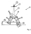
- FIG. 1 shows a movement device 1 with exactly two mutually parallel Recognize rails 2a, 2b, which are fixedly connected to a flat base 3.
- Each of the rails 2a, 2b carries in each case in the longitudinal direction of the respective rail 2a, 2b slidably arranged carriages 4a, 4b, 4c and 5a, 5b, 5c.
- Pro slide 4 a, 4 b, 4 c and 5 a, 5 b, 5 c is in each case a rod 6 with a base joint. 7 pivotally connected. At the other end, the bars 6 are each with platform joints 8 pivotally connected to a movable platform 9.
- the platform 9 By the displacement of the individual carriages 4a, 4b, 4c and 5a, 5b, 5c in the longitudinal direction the rails 2a, 2b, the platform 9 can be moved dynamically in all degrees of freedom become.
- the moving device 1 carries the platform. 9 a stalk 10, on the example of an aircraft model 11 for wind tunnel investigations is attached.
- the kinematics of the movement device is on a tool center point TCP on upper end of the stem 10 is designed.
- the center of gravity of the aircraft model 11 remains essentially unchanged.
- the swivel angle in the three spatial directions X, Y and Z allow the simulation of almost any steering maneuvers of the aircraft model 11 to. These are very dynamic maneuvers with accelerations of up to 2.5 G and more possible, which can be controlled very precisely.
- the rigidity of the movement device 1 is relatively constant and the first natural frequency is relatively high.
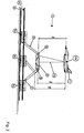
- FIG. 2 shows a front view of the movement device 1 from FIG.
- the carriages 2 a, 2 b are connected to each other by one Inclination angle ⁇ are inclined to the base plane 3.
- middle platform joints 8b on a deeper Level of the platform 9 as the front and rear platform joints 8a and 8c arranged are.
- FIG. 3 shows a side view of the movement device 1 from FIG. It is again clear that the central platform joints 8b lower with respect to the front and rear platform joints 8a and 8c with respect to the plane of the platform 9 or with respect to a plane perpendicular to the shaft 10 and passing through the tool center point TCP lie.
- the distance to this plane is designated in FIG. 3 for the front platform joints with h a , for the middle platform joints 8 b as h b and for the rear platform joints 8 c as h c .
- H a ⁇ h c ⁇ h b is designated in FIG. 3 for the front platform joints with h a , for the middle platform joints 8 b as h b and for the rear platform joints 8 c as h c .
- the platform joints 8b for the central rods 6 lie in the longitudinal direction of Rails 2 seen behind in this regard upstream platform joints 8c the rear legs 6.
- FIG. 4 shows a top view of the above-described movement device.
Abstract
Description
Die Erfindung betrifft eine Bewegungsvorrichtung mit einer Stewart-Plattform, bei der eine bewegliche Plattform mit Plattformgelenken gegenüber einer Basis mit mindestens sechs Stäben gelenkig verbunden ist, die Stäbe mit Basisgelenken basisseitig gelenkig auf Schlitten ruhen, die Schlitten auf zur Basis feststehenden Schienen in Längsrichtung der jeweiligen Schiene verschiebbar sind, wobei sich die Schienen parallel zueinander erstrecken, jeder Schlitten einen eigenen Antrieb hat, und die Schlitten voneinander unabhängig verfahrbar sind.The invention relates to a movement device with a Stewart platform, wherein a movable platform with platform joints opposite a base with at least six rods is articulated, the rods articulated base joints on the base side resting on sledges, the carriages on rails fixed to the base in the longitudinal direction the respective rail are displaceable, wherein the rails are parallel to each other each sled has its own drive, and the sledges from each other are independently movable.
Insbesondere betrifft die Erfindung eine Bewegungsvorrichtung zur Positionierung zur Bewegung eines Windkanalmodells in den drei translatorischen und drei rotatorischen Freiheitsgraden relativ zur freien Anströmung eines Windkanals. Das Modell wird dabei in Bauch- oder Rückenstielanordnung von einem Stiel so gehalten, dass sich die Bewegungsvorrichtung außerhalb der Windkanalmessstrecke befindet. Dadurch wird gewährleistet, dass möglichst wenig Störung in die Messstrecke eingebracht wird. Aufgrund der über den Hebelarm wirkenden aerodynamischen Lasten und der Massenkräfte muss die Bewegungsvorrichtung hinsichtlich einer größtmöglichen Steifigkeit bei gleichzeitiger Begrenzung der maximalen Antriebskraft optimiert werden. In particular, the invention relates to a movement device for positioning for Movement of a wind tunnel model in the three translational and three rotational Degrees of freedom relative to the free flow of a wind tunnel. The model will be there in abdominal or dorsal arrangement of a stem held so that the movement device located outside the wind tunnel measuring section. This will ensure that as little disturbance as possible is introduced into the measuring section. Due to the over the lever arm acting aerodynamic loads and the mass forces must the movement device in terms of maximum stiffness at the same time Limiting the maximum driving force to be optimized.
In vielen herkömmlichen Windkanälen wird die Aufhängung eines Modells in Heckstiel-, Bauchstiel- oder Rückenstielanordnung so realisiert, dass der Stiel zum Tragen des Modells aus der Messstrecke herausgeführt wird und von seriell außerhalb der Strömung angeordneten Bewegungsmechanismen gehalten wird.In many conventional wind tunnels, the suspension of a model in tailstalk, Bauchstiel- or back stem arrangement realized so that the stem for carrying the Model is led out of the measuring section and from serially out of the flow arranged movement mechanisms is held.
Die Modellaufhängung kann ebenfalls an Drähten erfolgen, die wiederum von einem außerhalb der Messstrecke befindlichen Mechanismus in der Art eines Marionettenantriebs gehalten werden. Die Lageänderung und die Stabilisierung im Raum erfolgt dann durch Zug an den Drähten gegen die Gravitationskraft. Solche Mechanismen sind nicht seriell.The model suspension can also be done on wires, which in turn of a outside the measuring section located mechanism in the manner of a puppet drive being held. The change in position and the stabilization in the room then takes place by pulling on the wires against the gravitational force. Such mechanisms are not serial.
Weiterhin sind zur Realisierung periodischer Bewegungen im Luftstrom zur Bestimmung dynamischer Derivativa Stielaufhängungen bekannt, die seriell so aufgebaut sind, dass je stets eine Achse jeweils eine weitere trägt. Bei drei Freiheitsgrad-Bewegungen führt dies bereits zu einer Reihenschaltung von groß und schwer bauenden Achsvorrichtungen für die Bewegungen des Nickens, Gierens und Rollens beispielsweise von Flugzeugmodellen. Durch die serielle, voneinander unabhängige Achsanordnung der Mechanismen muss eine Achse stets die Last aller nachgeordneten Achsen aufnehmen und entsprechend dimensioniert sein. Volumen und Gewicht steigt dadurch von Achse zu Achse und die Bewegungsflexibilität und Dynamik ist stark eingeschränkt. Zudem wird die Genauigkeit serieller Anordnungen durch das Fehlerfortpflanzungsgesetz durch die Genauigkeiten der Einzelachsen bestimmt und ist damit stets schlechter als bei der jeweiligen Einzelachse. Zudem ist jede einzelne Komponente individuell konstruiert, so dass der Aufwand für Fertigung und Montage relativ hoch ist.Furthermore, for the realization of periodic movements in the air flow for determination dynamic Derivativa handle suspensions, which are serially constructed so that each time an axle carries one more each. At three degrees of freedom movements leads this already to a series connection of large and heavy-built axle devices for the movements of pitching, yawing and rolling, for example, aircraft models. By the serial, independent axis arrangement of the mechanisms An axis must always pick up the load of all downstream axes and be dimensioned accordingly. Volume and weight thereby increase from axis to axis and the motion flexibility and dynamics is severely limited. moreover The accuracy of serial arrangements is passed through the error propagation law the accuracies of the individual axes determined and is therefore always worse than the respective single axis. In addition, every single component is designed individually, so that the effort for production and assembly is relatively high.
Aus der EP 0 868 255 B1 ist eine solche gattungsgemäße Bewegungsvorrichtung für
eine Werkzeugmaschine oder einen Manipulator bekannt. Die zu bewegende Plattform
kann im Raum bis zu drei translatorischen und drei rotatorischen Freiheitsgraden relativ
zu einer Basis bewegt werden.
Bei mindestens vier unabhängig voneinander auf parallelen Schienen verfahrbaren
Schlitten, kann trotz der eindimensionalen Vorzugsrichtung die bewegliche Plattform
nicht nur linear verfahren, sondern auch verkippt werden. Eine der Schienen soll dabei
genau zwei Schlitten tragen.Such a generic movement device for a machine tool or a manipulator is known from EP 0 868 255 B1. The platform to be moved can be moved in space up to three translational and three rotational degrees of freedom relative to a base.
In the case of at least four carriages which can be moved independently of one another on parallel rails, the movable platform can not only be moved linearly, but also tilted, in spite of the one-dimensional preferred direction. One of the rails should carry exactly two carriages.
Derartige Stewart-Plattformen haben den Vorteil einer großen Steifigkeit bei geringen zu bewegenden Massen.Such Stewart platforms have the advantage of high rigidity at low to moving masses.
In der DE 198 40 886 C2 ist eine Bewegungsvorrichtung mit Parallelstruktur offenbart, bei der fünf Führungsgelenkketten mit rotatorischen Motoren angetrieben werden. Ein sechster Stab ist davon unabhängig als Arbeitsspindel vorgesehen.In DE 198 40 886 C2 discloses a movement device with parallel structure, in which five guide link chains are driven by rotary motors. One Sixth rod is independently provided as a work spindle.
In der EP 1 234 632 A1 ist eine Werkzeugmaschine mit vier Freiheitsgraden beschrieben, bei der Stäbe in Parallelogrammen auf Schlitten getragen werden. Es sind zwei Schienen vorgesehen, wobei eine Schiene einen Schlitten und die andere Schiene drei Schlitten trägt. Eine Überkreuzung von Stäben führt zur Bindung von Freiheitsgraden.EP 1 234 632 A1 describes a machine tool with four degrees of freedom, in the bars are carried in parallelograms on sledges. There are two Rail provided with one rail a carriage and the other rail three Carriage carries. A crossover of bars leads to the binding of degrees of freedom.
In der EP 0 868 255 B1 ist eine Bewegungsvorrichtung mit drei Schienen vorgesehen, um einen Körper in drei bis sechs Freiheitsgraden zu bewegen.In EP 0 868 255 B1 a movement device with three rails is provided, to move a body in three to six degrees of freedom.
In der DE 101 51 631 B4 ist eine Bewegungsvorrichtung mit vier Schienen vorgesehen, die jeweils zwei Schlitten tragen. Die Schlitten sind parallel zueinander ausgerichtet und stehen sich räumlich gegenüber, so dass diese ein Rechteck aufspannen.In DE 101 51 631 B4 a movement device with four rails is provided, each carry two sleds. The carriages are aligned parallel to each other and are spatially opposite, so that they span a rectangle.
Das Problem bei derartigen Stewart-Plattformen ist es, eine in nahezu allen Bewegungssituationen konstante Steifigkeit bereitzustellen.The problem with such Stewart platforms is one in almost all motion situations to provide constant rigidity.
Aufgabe der Erfindung ist es daher, eine entsprechend verbesserte Bewegungsvorrichtung zu schaffen.The object of the invention is therefore to provide a correspondingly improved movement device to accomplish.
Die Aufgabe wird mit der gattungsgemäßen Bewegungsvorrichtung dadurch gelöst, dass genau zwei Schienen vorgesehen sind und jede Schiene mindestens drei Schlitten trägt und mindestens sechs Stäbe vorgesehen sind, wobei jeder Schlitten mindestens einen der Stäbe trägt. The object is achieved with the generic movement device characterized that exactly two rails are provided and each rail at least three carriages carries and at least six rods are provided, each carriage at least wearing one of the bars.
Es hat sich gezeigt, dass bei der Reduktion der Bewegungsvorrichtung auf zwei Schienen, die jeweils mindestens drei Schlitten tragen, die Steifigkeit des Systems verbessert werden kann und eine dynamische Bewegung in allen sechs Freiheitsgraden möglich ist. Dies gilt insbesondere für eine auf den Tool-Center-Point oberhalb eines Stiels auf der beweglichen Plattform ausgelegten Kinematik. Diese ist überraschenderweise trotz der Konzentration von mindestens drei Schlitten auf jeweils eine von zwei Schienen nicht eingeschränkt.It has been shown that in the reduction of the movement device on two rails, each carry at least three slides, the rigidity of the system improves can be and a dynamic movement in all six degrees of freedom possible is. This is especially true for one at the tool center point above a stalk the movable platform designed kinematics. This is surprisingly despite the concentration of at least three carriages on each one of two rails not limited.
Durch die Parallelschaltung der Schlittenantriebe ist die Fehlerfortpflanzung ebenfalls erheblich verringert, wobei sich Fehler in den einzelnen Schlittenantrieben im Idealfall sogar kompensieren können.Due to the parallel connection of the carriage drives the error propagation is also significantly reduced, with errors in the individual carriage drives ideally even compensate.
Es müssen nur zwei Linearführungen zusammen mit einem Wegmesssystem jeweils für sich auf Gradheit und Ebenheit ausgerichtet werden. Dabei können die Linearführungen zueinander windschief stehen. Alle übrigen Komponenten werden ohne besondere Genauigkeitsanforderungen montiert, weil die darauf entstehenden möglichen Abweichungen mit Kalibrierverfahren ausgeglichen werden können. Dies führt zu einem erheblich reduzierten Fertigungs- und Montageaufwand.There are only two linear guides together with a distance measuring system for each to be focused on degree and flatness. The linear guides skew each other. All other components are without special accuracy requirements mounted, because the resulting possible deviations can be compensated with calibration. This leads to a significant reduced manufacturing and assembly costs.
Besonders vorteilhaft ist es, wenn sich mindestens zwei einer gemeinsamen Schiene zugeordnete Stäbe räumlich überkreuzen, d. h. in der Vorderansicht und Seitenansicht der Plattform mindestens ein Kreuzungspunkt zwischen den sich überkreuzenden Stäben sichtbar ist. So können z. B. die auf einem hinteren Schlitten auf einer Schiene getragenen hinteren Stäbe an der Plattform vor dem Anlenkpunkt der von dem mittleren Schienen getragenen mittleren Stäbe angelenkt werden. Das heißt, dass für jede Schiene sich die mittleren und hinteren Stäbe überkreuzen. Auf diese Weise kann der erforderliche Einbauraum bei gleichem Bewegungsraum und mindestens gleicher Steifigkeit minimiert werden.It is particularly advantageous if at least two of a common rail spatially crossing assigned bars, d. H. in front view and side view the platform at least one crossing point between the crossing bars is visible. So z. B. carried on a rear slide on a rail rear bars on the platform in front of the pivot point of the middle Rail-mounted middle bars are hinged. That means that for each Rail the middle and rear bars cross each other. In this way, the Required installation space with the same movement space and at least equal rigidity be minimized.
Besonders vorteilhaft ist es, wenn die Schienen um einen Neigungswinkel α von zum Beispiel 26° zur Basisebene zueinander geneigt sind. Hierdurch kann die Steifigkeit und das dynamische Bewegungsverhalten weiter verbessert werden. It is particularly advantageous if the rails are inclined by an inclination angle α of Example 26 ° to the base plane inclined to each other. This allows the rigidity and the dynamic movement behavior can be further improved.
Weiterhin ist es vorteilhaft, wenn die Basisgelenke zum Tragen der Stäbe auf den Schlitten für eine gemeinsame Schiene zur Längsachse der Schiene seitlich mit unterschiedlichem Abstand versetzt angeordnet sind. Durch die Befestigung der Gelenke an unterschiedlichen Positionen an dem Schlitten kann die Kinematik weiter verbessert werden.Furthermore, it is advantageous if the base joints for supporting the rods on the Carriage for a common rail to the longitudinal axis of the rail laterally with different Distance offset are arranged. By attaching the joints different positions on the carriage, the kinematics can be further improved become.
Weiterhin ist es vorteilhaft, wenn mindestens ein Plattformgelenk der einer gemeinsamen Schiene zugeordneten Stäbe auf einer unterschiedlichen Ebene zu den anderen Plattformgelenken an der beweglichen Plattform angeordnet ist. Diese Anordnung kann Vorteile hinsichtlich der auf den Tool-Center-Point oberhalb der beweglichen Plattform bezogenen Kinematik und Steifigkeit haben.Furthermore, it is advantageous if at least one platform joint of a common Rail associated rods on a different level to the other Platform joints is arranged on the movable platform. This arrangement can Benefits regarding the tool center point above the moving platform related kinematics and stiffness.
Die Stäbe sind vorzugsweise starr und können in einer besonderen Ausführungsform auch längenveränderbar sein. Hierdurch werden weitere Bewegungsmöglichkeiten bereitgestellt, allerdings unter Reduktion der Steifigkeit.The rods are preferably rigid and, in a particular embodiment also be variable in length. This will provide more opportunities for movement, but with a reduction in stiffness.
Die Plattform ist vorzugsweise zum Tragen eines Modells für einen Windkanal vorgesehen, kann aber auch für Werkzeugmaschinen o. ä. genutzt werden. The platform is preferably provided for supporting a model for a wind tunnel, but can also be used for machine tools o. Ä.
Die Erfindung wird nachfolgend anhand der beigefügten Zeichnungen mit einem Ausführungsbeispiel näher erläutert. Es zeigen:
- Figur 1 -
- perspektivische Ansicht einer Bewegungsvorrichtung mit zwei Schienen, die jeweils drei Schlitten tragen;
- Figur 2 -
- Frontansicht der Bewegungsvorrichtung aus
Figur 1; - Figur 3 -
- Seitenansicht der Bewegungsvorrichtung aus
Figur 1; - Figur 4 -
- Draufsicht auf die Bewegungsvorrichtung aus
Figur 1.
- FIG. 1 -
- perspective view of a moving device with two rails, each carrying three carriages;
- FIG. 2 -
- Front view of the movement device of Figure 1;
- FIG. 3 -
- Side view of the movement device of Figure 1;
- FIG. 4 -
- Top view of the movement device of Figure 1.
Die Figur 1 lässt eine Bewegungsvorrichtung 1 mit genau zwei parallel zueinander verlaufenden
Schienen 2a, 2b erkennen, die fest mit einer ebenen Basis 3 verbunden sind.
Jede der Schienen 2a, 2b trägt jeweils in Längsrichtung der jeweiligen Schiene 2a, 2b
verschieblich angeordnete Schlitten 4a, 4b, 4c und 5a, 5b, 5c.FIG. 1 shows a
Pro Schlitten 4a, 4b, 4c und 5a, 5b, 5c ist jeweils ein Stab 6 mit einem Basisgelenk 7
drehgelenkig verbunden. An dem anderen Ende sind die Stäbe 6 jeweils mit Plattformgelenken
8 drehgelenkig mit einer beweglichen Plattform 9 verbunden.
Durch die Verschiebung der einzelnen Schlitten 4a, 4b, 4c und 5a, 5b, 5c in Längsrichtung
der Schienen 2a, 2b kann die Plattform 9 in allen Freiheitsgraden dynamisch bewegt
werden.By the displacement of the
In der dargestellten Ausführungsform der Bewegungsvorrichtung 1 trägt die Plattform 9
einen Stiel 10, auf der beispielsweise ein Flugzeugmodell 11 für Windkanaluntersuchungen
befestigt ist.In the illustrated embodiment of the moving
Die Kinematik der Bewegungsvorrichtung ist dabei auf einen Tool-Center-Point TCP am
oberen Ende des Stiels 10 ausgelegt. Der Schwerpunkt des Flugzeugmodells 11 bleibt
dabei im Wesentlichen unverändert. Die Schwenkwinkel in den drei Raumrichtungen X,
Y und Z lassen die Simulation nahezu beliebiger Lenkmanöver des Flugzeugmodells 11
zu. Dabei sind sehr dynamische Flugmanöver mit Beschleunigungen von bis zum 2,5 G
und mehr möglich, die sehr genau gesteuert werden können. Die Steifigkeit der Bewegungsvorrichtung
1 ist dabei relativ konstant und die erste Eigenfrequenz relativ hoch.The kinematics of the movement device is on a tool center point TCP on
upper end of the
Die Figur 2 lässt eine Vorderansicht der Bewegungsvorrichtung 1 aus der Figur 1 erkennen.
Es wird insbesondere deutlich, dass die Schlitten 2a, 2b zueinander um einen
Neigungswinkel α zur Basisebene 3 geneigt sind.FIG. 2 shows a front view of the
Weiterhin ist deutlich, dass die Basisgelenke 7 der Schlitten 4a, 4b, 4c, bzw. 5a, 5b, 5c
einer gemeinsamen Schiene 2a oder 2b zur Längsachse der jeweiligen Schiene 2a, 2b
seitlich mit unterschiedlichem Abstand d1, d2 versetzt angeordnet sind.Furthermore, it is clear that the base joints 7 of the
Weiterhin ist erkennbar, dass die mittleren Plattformgelenke 8b auf einer tieferen
Ebene der Plattform 9 als die vorderen und hinteren Plattformgelenke 8a und 8c angeordnet
sind.Furthermore, it can be seen that the middle platform joints 8b on a deeper
Level of the
Die Figur 3 lässt eine Seitenansicht der Bewegungsvorrichtung 1 aus der Figur 1 erkennen.
Es wird nochmals deutlich, dass die mittleren Plattformgelenke 8b in Bezug auf
die vorderen und hinteren Plattformgelenke 8a und 8c bezogen auf die Ebene der Plattform
9 oder bezogen auf eine senkrecht auf de Stiel 10 stehenden und durch den Tool-Center-Point
TCP verlaufenden Ebene tiefer liegen. Der Abstand zu dieser Ebene ist in
der Figur 3 für die vorderen Plattformgelenke mit ha, für die mittleren Plattformgelenke
8b mit hb und für die hinteren Plattformgelenke 8c mit hc bezeichnet. Dabei gilt
ha<hc<hb.FIG. 3 shows a side view of the
Weiterhin ist erkennbar, dass die beiden hinteren Stäbe 6 nach vorne und die vorderen
und mittleren Stäbe 6 nach hinten gerichtet sind. Das Plattformgelenk 8b der mittleren
Stäbe 6 liegt wie oben erläutert bezogen auf die Ebene durch den Tool-Center-Point
oder die Plattform 9 am tiefsten.Furthermore, it can be seen that the two
Die Plattformgelenke 8b für die mittleren Stäbe 6 liegen dabei in Längsrichtung der
Schienen 2 gesehen hinter den diesbezüglich vorgelagerten Plattformgelenken 8c der
hinteren Beine 6. The platform joints 8b for the
Die Figur 4 lässt eine Draufsicht auf die oben beschriebene Bewegungsvorrichtung erkennen.FIG. 4 shows a top view of the above-described movement device.
Es wird wiederum deutlich, dass genau zwei Schienen 2a, 2b vorgesehen sind, die parallel
zueinander verlaufen und jeweils drei Schlitten 4a, 4b und 4c und 5a, 5b, 5c tragen.It is again clear that exactly two
Weiterhin wird deutlich, dass die Plattformgelenke 8b der mittleren Stäbe 6 in Längsrichtung
der Schlitten 2a, 2b von links nach rechts gesehen hinter den Plattformgelenken
8c der hinteren Stäbe 6 liegen.Furthermore, it is clear that the platform joints 8b of the
Claims (9)
Applications Claiming Priority (2)
| Application Number | Priority Date | Filing Date | Title |
|---|---|---|---|
| DE102004030659 | 2004-06-24 | ||
| DE102004030659A DE102004030659B8 (en) | 2004-06-24 | 2004-06-24 | mover |
Publications (2)
| Publication Number | Publication Date |
|---|---|
| EP1609563A1 true EP1609563A1 (en) | 2005-12-28 |
| EP1609563B1 EP1609563B1 (en) | 2007-08-22 |
Family
ID=34937597
Family Applications (1)
| Application Number | Title | Priority Date | Filing Date |
|---|---|---|---|
| EP05013430A Not-in-force EP1609563B1 (en) | 2004-06-24 | 2005-06-22 | Positioning device with rods mounted on joints for a platform with six degrees of freedom |
Country Status (5)
| Country | Link |
|---|---|
| US (1) | US7909303B2 (en) |
| EP (1) | EP1609563B1 (en) |
| AT (1) | ATE370815T1 (en) |
| CA (1) | CA2510581C (en) |
| DE (2) | DE102004030659B8 (en) |
Cited By (9)
| Publication number | Priority date | Publication date | Assignee | Title |
|---|---|---|---|---|
| CN102519701A (en) * | 2011-12-06 | 2012-06-27 | 北京航空航天大学 | Vehicle-mounted aeroelastic test platform system |
| CN103144110A (en) * | 2013-02-26 | 2013-06-12 | 中国科学院自动化研究所 | Cantilever tail end vibration analysis and error compensation method |
| CN103158147A (en) * | 2013-03-28 | 2013-06-19 | 中国科学院自动化研究所 | Vibration compensation system and method of cantilever support fast self opening-and-closing shielding case |
| CN104308838A (en) * | 2014-09-26 | 2015-01-28 | 燕山大学 | High/low-frequency composite driving six-degree-of-freedom parallel movement platform |
| CN104458169A (en) * | 2014-09-26 | 2015-03-25 | 燕山大学 | High-and-low-frequency compound drive parallel two-dimensional rotating platform |
| CN105784316A (en) * | 2016-05-11 | 2016-07-20 | 中国空气动力研究与发展中心超高速空气动力研究所 | High-rigidness embedded device for multi-body separation test of hypersonic wind tunnel |
| CN106695759A (en) * | 2016-12-13 | 2017-05-24 | 九江精密测试技术研究所 | Three DOF (Degree of Freedom) parallel stable platform provided with symmetrical hybrid branches |
| CN109052257A (en) * | 2018-09-21 | 2018-12-21 | 南京理工大学 | A kind of elevating mechanism of solid space layout |
| CN113043228A (en) * | 2021-03-22 | 2021-06-29 | 江苏宏达数控科技股份有限公司 | Multi-station power tool rest posture adjusting detection platform and control method thereof |
Families Citing this family (17)
| Publication number | Priority date | Publication date | Assignee | Title |
|---|---|---|---|---|
| DE102004030659B8 (en) * | 2004-06-24 | 2007-01-18 | Ruprecht Altenburger | mover |
| CA2781788C (en) * | 2009-11-27 | 2015-11-03 | Mcmaster University | Automated in-bore mr guided robotic diagnostic and therapeutic system |
| CN102284868B (en) * | 2011-06-02 | 2013-03-20 | 常州大学 | Six-freedom-degree space series-parallel operating platform |
| FR2977649B1 (en) * | 2011-07-08 | 2013-08-02 | Thales Sa | LINEAR ACTUATOR |
| CN102615645A (en) * | 2012-04-12 | 2012-08-01 | 重庆大学 | Six-degree-of-freedom high-maneuvering high-accuracy practical parallel connection robot |
| CN103624786B (en) * | 2012-08-29 | 2016-12-21 | 塔莱斯公司 | Linear actuators |
| CN105881496A (en) * | 2014-11-07 | 2016-08-24 | 江南大学 | Decoupling hybrid mechanism with five freedom degrees of (1T2R)&(1T1R) |
| CN105563462A (en) * | 2014-11-07 | 2016-05-11 | 江南大学 | (1T2R) & 1T1R five-degree-of-freedom decoupling hybrid mechanism |
| CN105881495A (en) * | 2014-11-07 | 2016-08-24 | 江南大学 | Complete decoupling hybrid mechanism with five freedom degrees of (2T1R)&1T1R |
| CN105881499A (en) * | 2014-11-07 | 2016-08-24 | 江南大学 | Decoupling hybrid mechanism with five freedom degrees of (1T2R)&2T |
| CN106124157B (en) * | 2016-05-11 | 2018-11-06 | 中国空气动力研究与发展中心超高速空气动力研究所 | A kind of space mechanism in six degree of freedom for the experiment of hypersonic wind tunnel Multi-bodies Separation |
| HUE055829T2 (en) * | 2017-01-02 | 2021-12-28 | Manz Ag | Positioning unit |
| CN107414144A (en) * | 2017-03-24 | 2017-12-01 | 中国科学院长春光学精密机械与物理研究所 | Intelligent Counterboring apparatus based on six-degree-of-freedom parallel robot |
| CN107121256B (en) * | 2017-05-02 | 2018-10-09 | 中国空气动力研究与发展中心超高速空气动力研究所 | A kind of six degree of freedom captive trajectory testing method of continuous in-orbit movement |
| CN110450141B (en) * | 2019-08-30 | 2022-06-10 | 燕山大学 | Four-branch-chain six-degree-of-freedom hybrid mechanism |
| NL2027600B1 (en) * | 2021-02-19 | 2022-10-07 | Barge Master Ip B V | Offshore assembly comprising a motion compensation platform carrying an object with a height of 30-50 meters or more, motion compensation platform, as well as use of the assembly. |
| CN114441133B (en) * | 2021-12-28 | 2023-06-06 | 中国航天空气动力技术研究院 | Pose calibration method and equipment for attack angle-double-rotating-shaft mechanism for wind tunnel test |
Citations (3)
| Publication number | Priority date | Publication date | Assignee | Title |
|---|---|---|---|---|
| US6099217A (en) * | 1995-12-20 | 2000-08-08 | Wiegand; Alexander Konrad | Device for spatially moving a body with three to six degrees of freedom in a controlled manner |
| EP1234632A1 (en) * | 2001-02-23 | 2002-08-28 | Willemin Machines S.A. | Kinematic device for programmably supporting and positioning an end element in a machine or an instrument |
| US20040028516A1 (en) * | 2000-10-24 | 2004-02-12 | Torgny Brogardh | Industrial robot |
Family Cites Families (6)
| Publication number | Priority date | Publication date | Assignee | Title |
|---|---|---|---|---|
| US6240799B1 (en) * | 1998-05-26 | 2001-06-05 | Hexel Corporation | Triangular gimbal |
| DE19840886C2 (en) * | 1998-09-08 | 2003-03-13 | Juergen Hesselbach | Movement device with parallel structure |
| DE10063628B4 (en) * | 2000-12-20 | 2006-02-16 | Reichenbacher Hamuel Gmbh | Arrangement for translational positioning of a platform |
| DE10151631B4 (en) * | 2001-10-19 | 2004-02-12 | Volkswagen Ag | Movement and / or positioning device |
| TW546595B (en) * | 2002-07-23 | 2003-08-11 | Internet Motion Navigator Corp | Six-axis translation-type dynamic simulation device |
| DE102004030659B8 (en) * | 2004-06-24 | 2007-01-18 | Ruprecht Altenburger | mover |
-
2004
- 2004-06-24 DE DE102004030659A patent/DE102004030659B8/en not_active Expired - Fee Related
-
2005
- 2005-06-22 DE DE502005001277T patent/DE502005001277D1/en active Active
- 2005-06-22 AT AT05013430T patent/ATE370815T1/en not_active IP Right Cessation
- 2005-06-22 EP EP05013430A patent/EP1609563B1/en not_active Not-in-force
- 2005-06-23 CA CA2510581A patent/CA2510581C/en not_active Expired - Fee Related
- 2005-06-24 US US11/165,434 patent/US7909303B2/en not_active Expired - Fee Related
Patent Citations (3)
| Publication number | Priority date | Publication date | Assignee | Title |
|---|---|---|---|---|
| US6099217A (en) * | 1995-12-20 | 2000-08-08 | Wiegand; Alexander Konrad | Device for spatially moving a body with three to six degrees of freedom in a controlled manner |
| US20040028516A1 (en) * | 2000-10-24 | 2004-02-12 | Torgny Brogardh | Industrial robot |
| EP1234632A1 (en) * | 2001-02-23 | 2002-08-28 | Willemin Machines S.A. | Kinematic device for programmably supporting and positioning an end element in a machine or an instrument |
Cited By (16)
| Publication number | Priority date | Publication date | Assignee | Title |
|---|---|---|---|---|
| CN102519701B (en) * | 2011-12-06 | 2014-12-17 | 北京航空航天大学 | Vehicle-mounted aeroelastic test platform system |
| CN102519701A (en) * | 2011-12-06 | 2012-06-27 | 北京航空航天大学 | Vehicle-mounted aeroelastic test platform system |
| CN103144110A (en) * | 2013-02-26 | 2013-06-12 | 中国科学院自动化研究所 | Cantilever tail end vibration analysis and error compensation method |
| CN103144110B (en) * | 2013-02-26 | 2015-02-04 | 中国科学院自动化研究所 | Cantilever tail end vibration analysis and error compensation method |
| CN103158147B (en) * | 2013-03-28 | 2015-06-03 | 中国科学院自动化研究所 | Vibration compensation system and method of cantilever support fast self opening-and-closing shielding case |
| CN103158147A (en) * | 2013-03-28 | 2013-06-19 | 中国科学院自动化研究所 | Vibration compensation system and method of cantilever support fast self opening-and-closing shielding case |
| CN104308838B (en) * | 2014-09-26 | 2016-01-06 | 燕山大学 | Low-and high-frequency composite flooding six-freedom parallel sports platform |
| CN104458169A (en) * | 2014-09-26 | 2015-03-25 | 燕山大学 | High-and-low-frequency compound drive parallel two-dimensional rotating platform |
| CN104308838A (en) * | 2014-09-26 | 2015-01-28 | 燕山大学 | High/low-frequency composite driving six-degree-of-freedom parallel movement platform |
| CN104458169B (en) * | 2014-09-26 | 2017-02-15 | 燕山大学 | High-and-low-frequency compound drive parallel two-dimensional rotating platform |
| CN105784316A (en) * | 2016-05-11 | 2016-07-20 | 中国空气动力研究与发展中心超高速空气动力研究所 | High-rigidness embedded device for multi-body separation test of hypersonic wind tunnel |
| CN105784316B (en) * | 2016-05-11 | 2018-06-29 | 中国空气动力研究与发展中心超高速空气动力研究所 | A kind of high rigidity embedded equipment for the experiment of hypersonic wind tunnel Multi-bodies Separation |
| CN106695759A (en) * | 2016-12-13 | 2017-05-24 | 九江精密测试技术研究所 | Three DOF (Degree of Freedom) parallel stable platform provided with symmetrical hybrid branches |
| CN106695759B (en) * | 2016-12-13 | 2023-04-11 | 九江精密测试技术研究所 | Three-degree-of-freedom parallel stable platform with symmetrical parallel-serial branches |
| CN109052257A (en) * | 2018-09-21 | 2018-12-21 | 南京理工大学 | A kind of elevating mechanism of solid space layout |
| CN113043228A (en) * | 2021-03-22 | 2021-06-29 | 江苏宏达数控科技股份有限公司 | Multi-station power tool rest posture adjusting detection platform and control method thereof |
Also Published As
| Publication number | Publication date |
|---|---|
| US7909303B2 (en) | 2011-03-22 |
| CA2510581C (en) | 2013-02-05 |
| ATE370815T1 (en) | 2007-09-15 |
| EP1609563B1 (en) | 2007-08-22 |
| CA2510581A1 (en) | 2005-12-24 |
| DE102004030659A1 (en) | 2006-02-02 |
| DE102004030659B8 (en) | 2007-01-18 |
| DE102004030659B4 (en) | 2006-08-10 |
| US20060254380A1 (en) | 2006-11-16 |
| DE502005001277D1 (en) | 2007-10-04 |
Similar Documents
| Publication | Publication Date | Title |
|---|---|---|
| EP1609563B1 (en) | Positioning device with rods mounted on joints for a platform with six degrees of freedom | |
| EP2055447B1 (en) | Parallel cinematic device | |
| DE3931753C2 (en) | ||
| DE19709851A1 (en) | Process and programmable positioner for the stress-free assembly of assemblies | |
| DE102015116808B3 (en) | Robot, XY table for such a robot and linear transport system | |
| EP0791438B1 (en) | Device for moving a body in space | |
| DE202014104858U1 (en) | Trackless tugger train | |
| DE3202353A1 (en) | PANTOGRAPH ROD | |
| DE202005015434U1 (en) | Controller with control stick for aircraft has 2 control shafts rotatably mounted in fixed position on common frame, joint with free-running device per control shaft for tilting control stick in plane parallel to respective control shaft | |
| EP1930132A1 (en) | Device, in particular for positioning objects | |
| EP1924409B1 (en) | Device for swiveling objects | |
| EP1561550A1 (en) | Device for spatially positioning and supporting a working element in connection with a base element and use of such a device | |
| EP2233256B1 (en) | Drive device | |
| DE102012008559B4 (en) | Robot arm module for a robot arm or robot arm | |
| EP1228838B1 (en) | Kinematical device for moving a carrier | |
| WO2002047976A2 (en) | Aerodynamic wing with at least partially variable curvature and structural joints | |
| DE10151631B4 (en) | Movement and / or positioning device | |
| DE102012025432B3 (en) | Robot arrangement i.e. parallel rope robot, has structure components spatially arranged along platform and counter bearings such that torque oriented around one of axes is produced or torque oriented around another axis is produced | |
| DE102009056582A1 (en) | Handling system for moving object, particularly platform, comprises holding structure, multiple flexible elements, and drive element, where object is connected with drive element by flexible elements | |
| EP3000685A1 (en) | Rail vehicle with pitch support device | |
| EP2749862B1 (en) | Test device for axle-less attachments attached to a three point power lift | |
| AT502426B1 (en) | Parallel kinematic device for connecting fixed platform to mobile platform uses three connecting elements engaging with common point of one of platforms to form a triple point with simple mechanical configuration | |
| AT502980B1 (en) | Parallel kinematic device for connecting fixed platform to mobile platform uses three connecting elements engaging with common point of one of platforms to form a triple point with simple mechanical configuration | |
| DE19757885A1 (en) | Device for positioning a first machine part relative to a second machine part | |
| DE19902867A1 (en) | Multi-axle parallel rods kinematic system has linear drives, linear guide tracks, frame, and spindle nut system |
Legal Events
| Date | Code | Title | Description |
|---|---|---|---|
| PUAI | Public reference made under article 153(3) epc to a published international application that has entered the european phase |
Free format text: ORIGINAL CODE: 0009012 |
|
| AK | Designated contracting states |
Kind code of ref document: A1 Designated state(s): AT BE BG CH CY CZ DE DK EE ES FI FR GB GR HU IE IS IT LI LT LU MC NL PL PT RO SE SI SK TR |
|
| AX | Request for extension of the european patent |
Extension state: AL BA HR LV MK YU |
|
| 17P | Request for examination filed |
Effective date: 20060610 |
|
| AKX | Designation fees paid |
Designated state(s): AT BE BG CH CY CZ DE DK EE ES FI FR GB GR HU IE IS IT LI LT LU MC NL PL PT RO SE SI SK TR |
|
| GRAP | Despatch of communication of intention to grant a patent |
Free format text: ORIGINAL CODE: EPIDOSNIGR1 |
|
| GRAS | Grant fee paid |
Free format text: ORIGINAL CODE: EPIDOSNIGR3 |
|
| GRAA | (expected) grant |
Free format text: ORIGINAL CODE: 0009210 |
|
| AK | Designated contracting states |
Kind code of ref document: B1 Designated state(s): AT BE BG CH CY CZ DE DK EE ES FI FR GB GR HU IE IS IT LI LT LU MC NL PL PT RO SE SI SK TR |
|
| REG | Reference to a national code |
Ref country code: GB Ref legal event code: FG4D Free format text: NOT ENGLISH |
|
| REG | Reference to a national code |
Ref country code: CH Ref legal event code: EP |
|
| REG | Reference to a national code |
Ref country code: IE Ref legal event code: FG4D Free format text: LANGUAGE OF EP DOCUMENT: GERMAN |
|
| REF | Corresponds to: |
Ref document number: 502005001277 Country of ref document: DE Date of ref document: 20071004 Kind code of ref document: P |
|
| GBT | Gb: translation of ep patent filed (gb section 77(6)(a)/1977) |
Effective date: 20071129 |
|
| PG25 | Lapsed in a contracting state [announced via postgrant information from national office to epo] |
Ref country code: NL Free format text: LAPSE BECAUSE OF FAILURE TO SUBMIT A TRANSLATION OF THE DESCRIPTION OR TO PAY THE FEE WITHIN THE PRESCRIBED TIME-LIMIT Effective date: 20070822 Ref country code: ES Free format text: LAPSE BECAUSE OF FAILURE TO SUBMIT A TRANSLATION OF THE DESCRIPTION OR TO PAY THE FEE WITHIN THE PRESCRIBED TIME-LIMIT Effective date: 20071203 Ref country code: FI Free format text: LAPSE BECAUSE OF FAILURE TO SUBMIT A TRANSLATION OF THE DESCRIPTION OR TO PAY THE FEE WITHIN THE PRESCRIBED TIME-LIMIT Effective date: 20070822 Ref country code: IS Free format text: LAPSE BECAUSE OF FAILURE TO SUBMIT A TRANSLATION OF THE DESCRIPTION OR TO PAY THE FEE WITHIN THE PRESCRIBED TIME-LIMIT Effective date: 20071222 Ref country code: BG Free format text: LAPSE BECAUSE OF FAILURE TO SUBMIT A TRANSLATION OF THE DESCRIPTION OR TO PAY THE FEE WITHIN THE PRESCRIBED TIME-LIMIT Effective date: 20071122 Ref country code: LT Free format text: LAPSE BECAUSE OF FAILURE TO SUBMIT A TRANSLATION OF THE DESCRIPTION OR TO PAY THE FEE WITHIN THE PRESCRIBED TIME-LIMIT Effective date: 20070822 |
|
| NLV1 | Nl: lapsed or annulled due to failure to fulfill the requirements of art. 29p and 29m of the patents act | ||
| PG25 | Lapsed in a contracting state [announced via postgrant information from national office to epo] |
Ref country code: PL Free format text: LAPSE BECAUSE OF FAILURE TO SUBMIT A TRANSLATION OF THE DESCRIPTION OR TO PAY THE FEE WITHIN THE PRESCRIBED TIME-LIMIT Effective date: 20070822 |
|
| REG | Reference to a national code |
Ref country code: IE Ref legal event code: FD4D |
|
| ET | Fr: translation filed | ||
| PG25 | Lapsed in a contracting state [announced via postgrant information from national office to epo] |
Ref country code: GR Free format text: LAPSE BECAUSE OF FAILURE TO SUBMIT A TRANSLATION OF THE DESCRIPTION OR TO PAY THE FEE WITHIN THE PRESCRIBED TIME-LIMIT Effective date: 20071123 Ref country code: DK Free format text: LAPSE BECAUSE OF FAILURE TO SUBMIT A TRANSLATION OF THE DESCRIPTION OR TO PAY THE FEE WITHIN THE PRESCRIBED TIME-LIMIT Effective date: 20070822 |
|
| REG | Reference to a national code |
Ref country code: CH Ref legal event code: NV Representative=s name: E. BLUM & CO. AG PATENT- UND MARKENANWAELTE VSP |
|
| PG25 | Lapsed in a contracting state [announced via postgrant information from national office to epo] |
Ref country code: SK Free format text: LAPSE BECAUSE OF FAILURE TO SUBMIT A TRANSLATION OF THE DESCRIPTION OR TO PAY THE FEE WITHIN THE PRESCRIBED TIME-LIMIT Effective date: 20070822 Ref country code: CZ Free format text: LAPSE BECAUSE OF FAILURE TO SUBMIT A TRANSLATION OF THE DESCRIPTION OR TO PAY THE FEE WITHIN THE PRESCRIBED TIME-LIMIT Effective date: 20070822 Ref country code: PT Free format text: LAPSE BECAUSE OF FAILURE TO SUBMIT A TRANSLATION OF THE DESCRIPTION OR TO PAY THE FEE WITHIN THE PRESCRIBED TIME-LIMIT Effective date: 20080122 Ref country code: IE Free format text: LAPSE BECAUSE OF FAILURE TO SUBMIT A TRANSLATION OF THE DESCRIPTION OR TO PAY THE FEE WITHIN THE PRESCRIBED TIME-LIMIT Effective date: 20070822 |
|
| PLBE | No opposition filed within time limit |
Free format text: ORIGINAL CODE: 0009261 |
|
| STAA | Information on the status of an ep patent application or granted ep patent |
Free format text: STATUS: NO OPPOSITION FILED WITHIN TIME LIMIT |
|
| PG25 | Lapsed in a contracting state [announced via postgrant information from national office to epo] |
Ref country code: RO Free format text: LAPSE BECAUSE OF FAILURE TO SUBMIT A TRANSLATION OF THE DESCRIPTION OR TO PAY THE FEE WITHIN THE PRESCRIBED TIME-LIMIT Effective date: 20070822 Ref country code: SE Free format text: LAPSE BECAUSE OF FAILURE TO SUBMIT A TRANSLATION OF THE DESCRIPTION OR TO PAY THE FEE WITHIN THE PRESCRIBED TIME-LIMIT Effective date: 20071122 |
|
| 26N | No opposition filed |
Effective date: 20080526 |
|
| BERE | Be: lapsed |
Owner name: AUL, PETER Effective date: 20080630 Owner name: DEUTSCHES ZENTRUM FUR LUFT- UND RAUMFAHRT E.V. Effective date: 20080630 Owner name: ALTENBURGER, RUPRECHT Effective date: 20080630 |
|
| PG25 | Lapsed in a contracting state [announced via postgrant information from national office to epo] |
Ref country code: MC Free format text: LAPSE BECAUSE OF NON-PAYMENT OF DUE FEES Effective date: 20080630 |
|
| PG25 | Lapsed in a contracting state [announced via postgrant information from national office to epo] |
Ref country code: BE Free format text: LAPSE BECAUSE OF NON-PAYMENT OF DUE FEES Effective date: 20080630 |
|
| PG25 | Lapsed in a contracting state [announced via postgrant information from national office to epo] |
Ref country code: EE Free format text: LAPSE BECAUSE OF FAILURE TO SUBMIT A TRANSLATION OF THE DESCRIPTION OR TO PAY THE FEE WITHIN THE PRESCRIBED TIME-LIMIT Effective date: 20070822 |
|
| PG25 | Lapsed in a contracting state [announced via postgrant information from national office to epo] |
Ref country code: SI Free format text: LAPSE BECAUSE OF FAILURE TO SUBMIT A TRANSLATION OF THE DESCRIPTION OR TO PAY THE FEE WITHIN THE PRESCRIBED TIME-LIMIT Effective date: 20070822 |
|
| PG25 | Lapsed in a contracting state [announced via postgrant information from national office to epo] |
Ref country code: CY Free format text: LAPSE BECAUSE OF FAILURE TO SUBMIT A TRANSLATION OF THE DESCRIPTION OR TO PAY THE FEE WITHIN THE PRESCRIBED TIME-LIMIT Effective date: 20070822 |
|
| PG25 | Lapsed in a contracting state [announced via postgrant information from national office to epo] |
Ref country code: AT Free format text: LAPSE BECAUSE OF NON-PAYMENT OF DUE FEES Effective date: 20080622 |
|
| PG25 | Lapsed in a contracting state [announced via postgrant information from national office to epo] |
Ref country code: LU Free format text: LAPSE BECAUSE OF NON-PAYMENT OF DUE FEES Effective date: 20080622 Ref country code: HU Free format text: LAPSE BECAUSE OF FAILURE TO SUBMIT A TRANSLATION OF THE DESCRIPTION OR TO PAY THE FEE WITHIN THE PRESCRIBED TIME-LIMIT Effective date: 20080223 |
|
| PG25 | Lapsed in a contracting state [announced via postgrant information from national office to epo] |
Ref country code: TR Free format text: LAPSE BECAUSE OF FAILURE TO SUBMIT A TRANSLATION OF THE DESCRIPTION OR TO PAY THE FEE WITHIN THE PRESCRIBED TIME-LIMIT Effective date: 20070822 |
|
| REG | Reference to a national code |
Ref country code: FR Ref legal event code: PLFP Year of fee payment: 11 |
|
| PGFP | Annual fee paid to national office [announced via postgrant information from national office to epo] |
Ref country code: CH Payment date: 20150528 Year of fee payment: 11 Ref country code: GB Payment date: 20150526 Year of fee payment: 11 |
|
| REG | Reference to a national code |
Ref country code: DE Ref legal event code: R082 Ref document number: 502005001277 Country of ref document: DE Representative=s name: GRAMM, LINS & PARTNER PATENT- UND RECHTSANWAEL, DE |
|
| PGFP | Annual fee paid to national office [announced via postgrant information from national office to epo] |
Ref country code: IT Payment date: 20150611 Year of fee payment: 11 Ref country code: FR Payment date: 20150528 Year of fee payment: 11 |
|
| REG | Reference to a national code |
Ref country code: DE Ref legal event code: R084 Ref document number: 502005001277 Country of ref document: DE |
|
| REG | Reference to a national code |
Ref country code: CH Ref legal event code: PL |
|
| GBPC | Gb: european patent ceased through non-payment of renewal fee |
Effective date: 20160622 |
|
| REG | Reference to a national code |
Ref country code: FR Ref legal event code: ST Effective date: 20170228 |
|
| PG25 | Lapsed in a contracting state [announced via postgrant information from national office to epo] |
Ref country code: CH Free format text: LAPSE BECAUSE OF NON-PAYMENT OF DUE FEES Effective date: 20160630 Ref country code: LI Free format text: LAPSE BECAUSE OF NON-PAYMENT OF DUE FEES Effective date: 20160630 Ref country code: FR Free format text: LAPSE BECAUSE OF NON-PAYMENT OF DUE FEES Effective date: 20160630 |
|
| PG25 | Lapsed in a contracting state [announced via postgrant information from national office to epo] |
Ref country code: GB Free format text: LAPSE BECAUSE OF NON-PAYMENT OF DUE FEES Effective date: 20160622 |
|
| PG25 | Lapsed in a contracting state [announced via postgrant information from national office to epo] |
Ref country code: IT Free format text: LAPSE BECAUSE OF NON-PAYMENT OF DUE FEES Effective date: 20160622 |
|
| PGFP | Annual fee paid to national office [announced via postgrant information from national office to epo] |
Ref country code: DE Payment date: 20170623 Year of fee payment: 13 |
|
| REG | Reference to a national code |
Ref country code: DE Ref legal event code: R119 Ref document number: 502005001277 Country of ref document: DE |
|
| PG25 | Lapsed in a contracting state [announced via postgrant information from national office to epo] |
Ref country code: DE Free format text: LAPSE BECAUSE OF NON-PAYMENT OF DUE FEES Effective date: 20190101 |