EP1929618B1 - Kontrolle und diagnose eines stromversorgungssystems - Google Patents
Kontrolle und diagnose eines stromversorgungssystems Download PDFInfo
- Publication number
- EP1929618B1 EP1929618B1 EP06802798.6A EP06802798A EP1929618B1 EP 1929618 B1 EP1929618 B1 EP 1929618B1 EP 06802798 A EP06802798 A EP 06802798A EP 1929618 B1 EP1929618 B1 EP 1929618B1
- Authority
- EP
- European Patent Office
- Prior art keywords
- data
- command
- bits
- fault
- gating signal
- Prior art date
- Legal status (The legal status is an assumption and is not a legal conclusion. Google has not performed a legal analysis and makes no representation as to the accuracy of the status listed.)
- Ceased
Links
Images



Classifications
-
- H—ELECTRICITY
- H02—GENERATION; CONVERSION OR DISTRIBUTION OF ELECTRIC POWER
- H02M—APPARATUS FOR CONVERSION BETWEEN AC AND AC, BETWEEN AC AND DC, OR BETWEEN DC AND DC, AND FOR USE WITH MAINS OR SIMILAR POWER SUPPLY SYSTEMS; CONVERSION OF DC OR AC INPUT POWER INTO SURGE OUTPUT POWER; CONTROL OR REGULATION THEREOF
- H02M7/00—Conversion of AC power input into DC power output; Conversion of DC power input into AC power output
- H02M7/42—Conversion of DC power input into AC power output without possibility of reversal
- H02M7/44—Conversion of DC power input into AC power output without possibility of reversal by static converters
- H02M7/48—Conversion of DC power input into AC power output without possibility of reversal by static converters using discharge tubes with control electrode or semiconductor devices with control electrode
- H02M7/483—Converters with outputs that each can have more than two voltages levels
- H02M7/49—Combination of the output voltage waveforms of a plurality of converters
-
- G—PHYSICS
- G06—COMPUTING OR CALCULATING; COUNTING
- G06F—ELECTRIC DIGITAL DATA PROCESSING
- G06F1/00—Details not covered by groups G06F3/00 - G06F13/00 and G06F21/00
- G06F1/26—Power supply means, e.g. regulation thereof
-
- H—ELECTRICITY
- H02—GENERATION; CONVERSION OR DISTRIBUTION OF ELECTRIC POWER
- H02M—APPARATUS FOR CONVERSION BETWEEN AC AND AC, BETWEEN AC AND DC, OR BETWEEN DC AND DC, AND FOR USE WITH MAINS OR SIMILAR POWER SUPPLY SYSTEMS; CONVERSION OF DC OR AC INPUT POWER INTO SURGE OUTPUT POWER; CONTROL OR REGULATION THEREOF
- H02M7/00—Conversion of AC power input into DC power output; Conversion of DC power input into AC power output
- H02M7/42—Conversion of DC power input into AC power output without possibility of reversal
- H02M7/44—Conversion of DC power input into AC power output without possibility of reversal by static converters
- H02M7/48—Conversion of DC power input into AC power output without possibility of reversal by static converters using discharge tubes with control electrode or semiconductor devices with control electrode
-
- H—ELECTRICITY
- H02—GENERATION; CONVERSION OR DISTRIBUTION OF ELECTRIC POWER
- H02M—APPARATUS FOR CONVERSION BETWEEN AC AND AC, BETWEEN AC AND DC, OR BETWEEN DC AND DC, AND FOR USE WITH MAINS OR SIMILAR POWER SUPPLY SYSTEMS; CONVERSION OF DC OR AC INPUT POWER INTO SURGE OUTPUT POWER; CONTROL OR REGULATION THEREOF
- H02M1/00—Details of apparatus for conversion
- H02M1/0003—Details of control, feedback or regulation circuits
- H02M1/0012—Control circuits using digital or numerical techniques
Definitions
- a power supply to control the flow of energy between a first alternating current (AC) system and a second AC system is required in a variety of commercial and industrial applications, such as the control of AC motor operation.
- Some such power supplies convert the energy from a first frequency and voltage to a second frequency and voltage.
- One way to implement such a system is with one or more power cells that include two solid state converters with an intermediate DC link.
- a power cell is an electrical device that has a three-phase alternating current input and a single-phase alternating current output.
- U.S. Patent No. 5,625,545 to Hammond Referring to FIG.
- Hammond discloses a power cell 110 that includes an AC-to-direct current (DC) converter 112 - here, a three-phase diode-bridge rectifier - one or more DC capacitors 114 , and a DC-to-AC converter 116 - here, an H-bridge inverter.
- the rectifier 112 converts the input 118 AC voltage to a substantially constant DC voltage that is supported by the capacitors 114 that are connected across the rectifier 112 output.
- the output stage of the inverter 110 includes an H-bridge inverter 116 that includes two poles, a left pole and a right pole, each with two devices.
- the inverter 110 transforms the DC voltage across the DC capacitors 114 to an AC output 120 using pulse-width modulation (PWM) of the semiconductor devices in the H-bridge inverter 116 .
- the rectifier 112 may include three pairs of current-controlling devices, such as insulated gate bipolar transistors (IGBTs), diodes, switches or other devices.
- the inverter 116 may contain two pairs of such devices.
- a circuit including power cells such as 110 in FIG. 1 when connected to a load, such as a motor, can provide power from an input source to the motor when operating in the motoring mode.
- a power cell may sometimes be referred to as a unidirectional or two-quadrant (2Q) cell.
- 2Q two-quadrant
- the regeneration mode when the motor speed needs to be reduced, power from the motor needs to be absorbed by the inverter.
- This mode of operation when power must be absorbed by the inverter, is referred to as the regeneration mode.
- some or all of the power cells are typically regenerative or four-quadrant (4Q) cells.
- WO 0131770 describes a method and system for predicting malfunctions in a power inverter having one or more legs connected between first and second voltage buses. Each leg has respective first and second controllable switches coupled in series to one another.
- the method allows for applying predetermined respective voltages at the first and second buses and for selectively actuating the first and second switches between respective conductive or non-conductive states.
- a monitoring step allows for monitoring predetermined electrical parameters generated in the inverter in response to the applied voltages as the first and second switches are respectively actuated.
- the parameters are based on a first set of operational and environmental conditions. Adjustment and comparison with nominal values is allowed for.
- a method of monitoring a power delivery system includes receiving a gating signal packet from a component of a power delivery system.
- the received packet includes bits that correspond to the status of one or more devices within the component.
- the packet also includes one or more bits that contain a subset of stored data that was retrieved from a component memory.
- the method also includes repeating the receiving until multiple gating signal packets are received.
- the multiple gating signal packets collectively contain the stored data, so that the subsets of the data point may be assembled into the stored data.
- the one or more bits that contain a subset of stored data may be mode bits of the gating signal packet.
- the method also includes first delivering a gating signal packet to the component before the receiving.
- the delivered packet includes a plurality of bits that command operation of one or more devices within the component.
- the packet includes one or more bits that contain a subset of a command to request the data point.
- the method may further include using the assembled stored data to determine a component fault diagnosis.
- the packets also may include bits corresponding to data that is predictive of failure of a component, and the method also may include delivering a control command to the power cell based on the predictive data.
- the stored data may include fault data such as a fault code, a time code or a device identifier.
- the stored data may include waveform information such as current data, voltage data, temperature data, or phase data.
- a method of operating a power cell includes receiving a gating signal packet from a power cell.
- the received packet includes bits that correspond to the status of one or more devices within the cell, and the packet also includes one or more bits that contain a subset of stored data that was retrieved from a cell memory.
- the receiving of additional packets occurs until multiple gating signal packets that collectively contain the stored data are received.
- the method then includes assembling the subsets of the data point into the stored data.
- the method may include delivering a gating signal packet to the power cell.
- the delivered packet may include bits that command operation of one or more devices within the cell, and the packet may includes one or more bits that contain a subset of a command to request the data point.
- the delivering may be repeated until multiple gating signal packets that collectively contain the command are delivered.
- the method may then include assembling the subsets of the command into the command.
- a method of operating a power cell includes delivering a gating signal packet to a power cell.
- the delivered packet includes a plurality of bits that command operation of one or more devices within the cell.
- the packet also includes one or more bits that contain a subset of a command to request a data point.
- the delivering is repeated until a plurality of gating signal packets are delivered, wherein the plurality of gating signal packets collectively contain the command.
- the method may then include assembling the subsets of the command into the command.
- the method also may include receiving a gating signal packet from the power cell in response to the command, wherein the received packet includes a plurality of bits that correspond to the status of one or more devices within the cell.
- the packet also may include one or more bits that contain a subset of stored data that was retrieved from a cell memory.
- the receiving may be repeated until a plurality of gating signal packets are received, wherein the plurality of received gating signal packets collectively contain the stored data.
- the method may then include assembling the subsets of the stored data into the stored data.
- a multi-level power circuit includes a plurality of power cells to drive a load.
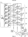
- FIG. 2 illustrates an exemplary embodiment of a circuit having such power cells.
- a transformer 210 delivers three-phase, medium-voltage power to a load 230 such as a three-phase induction motor via an array of single-phase inverters (also referred to as power cells).
- the transformer 210 includes primary windings 212 that excite a number of secondary windings 214 - 225 .
- primary winding 212 is illustrated as having a star configuration, a mesh configuration is also possible.
- secondary windings 214 - 225 are illustrated as having a mesh configuration, star-configured secondary windings are possible, or a combination of star and mesh windings may be used. Further, the number of secondary windings illustrated in FIG. 2 is merely exemplary, and other numbers of secondary windings are possible.
- the circuit may be used for medium voltage applications or, in some embodiments, other applications.
- medium voltage means a rated voltage greater than 690 volts (V) and less than 69 kilovolts (kV). In some embodiments, medium voltage may include voltages between about 1000 V and about 69 kV.
- any number of three-phase sets of power cells may be connected between the transformer 210 and the load 230 .
- the system may include a first set of power cells 251-253 , a second set of power cells 261-263 , a third set of power cells 271-273 , and a fourth set of power cells 281-283 . Fewer than four sets, or more than four sets, are possible.
- a central control system 295 sends command signals to a local controller 292 and/or cell-level controls in each cell over fiber optics or another wired or wireless communications medium 290 .
- the modulation of each power cell in the system may be controlled using gating signals that are transmitted to each cell from the controller 295 .
- a gating signal may be a two-pole signal that serves as an "on/off'' signal or an "enable/disable” command to one or more devices in the cell.
- the signals originate from the controller 295 in order to reduce the harmonic content that is presented to the load by the signals.
- the cells may return a gating signal that acknowledges the fault status of a portion of the cell.
- an 8-bit gating command signal packet 310 delivered to a cell may include a fire (enable/disable) right pole bit 311 and a fire (enable/disable) left pole bit 312 .
- One signal may be used per pair of IGBTs or other switches in the cell, and these bits may control the on/off status of each IGBT.
- the signal also may include a temperature synchronization bit 313 , an enable cell bypass bit 314 , two mode bits 315 and 316 , an enable output bit 317 , and a parity bit 318 .
- the mode bits have been set to zero, and the mode bits were occasionally used to request information from a cell when the cell was powered off.
- an 8-bit return signal packet 350 received by the central controller from a cell may include a power supply status or validity bit 351 , cell bypass enabled bit 352 , cell temperature feedback bit 353 , cell phase loss bit 354 , a fault bit that indicates whether or not a fault exists 355 , two mode bits 356 and 357 that are normally zero, and a parity bit 358 .
- the fault data provided by the return signal consisted solely of a "yes/no" indicator of whether or not a fault exists.
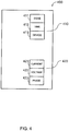
- some or all of the power cells 400 may include a memory portion, such as a non-volatile memory, that stores fault information to create a fault log 410 for the system.
- the fault information may include a fault code 411 , and optionally a time stamp 412 and an indicator 413 of which device within the power cell is faulted.
- the fault code may be a multi-character code, such as a binary, numeric or alphanumeric code, that corresponds to a fault type. Examples of fault codes may include items such as: 0000100 - DC over-voltage fault; 0010110 - arc detected within the cell; and 0001101 - loss of thermal sensor on right pole.
- the optional time stamp may relate to an actual time, or it may relate to a counter such that the time is related to a zero count on the counter.
- the memory holding the fault log may receive data from the cells within the device as soon as a fault occurs.
- the fault log may include data that helps to diagnose the cause and/or consequences of a fault.
- Fault log data may include, for example: current measurements at various points within the cell; voltage measurements at various points within the cell; frequency; voltage and current imbalance; DC ripple; and other data.
- fault data be stored in non-volatile memory in order to create a permanent or semi-permanent record of fault data.
- the cells also may include a memory portion, such as a volatile memory portion, that stores cell waveform data 420 , such as current amplitude 421 , voltage 422 , and phase 423 .
- This data may be captured on a real-time basis and stored in volatile memory so that older data is purged after a certain amount of newer waveform data is received.
- the amount of waveform data held in the memory may be limited by the size of the memory, the size of a buffer or cache, a predetermined setting, or any other factor.
- the gating signals may be used to capture fault data from the fault log, such as a request for one or more data points from the fault log. In some embodiments, referring to FIG. 5 , this may be done by the central controller by selecting a command 501 to provide certain fault information.
- the command may be a multi-bit command, that the method may include dividing the command 503 into subsets of bits and placing 505 each subset into an appropriate portion of the gating command signal packet, such as the two mode bits. If the placing has not placed all of the bits of the command into command signals, the process selects a next gating packet 507 and repeats the process until the command has been fully placed among a group of gating signal packets.
- the command is assembled 509 at the cell or the local control.
- the command may be split between multiple successive or multiplexed gating signal packets so that when a set of packets is received by the cell, the cell may extract and assemble the command from multiple gating signal packets.
- a 16-bit command may be divided among 8 gating signal packets, and the command is assembled when all of the 8 gating signal packets are received by cell or local control.
- a 16-bit command may be divided among 16 gating signal packets, with one mode bit of each gating signal including a bit of the command. In such situations, it may be desirable to also provide each command with a 17 th packet for synchronization.
- multiple commands may be assembled into a packet of information.
- the system may then return the requested data to the central controller by a similar process that includes dividing the data 511 into subsets, distributing 513 the data into the two mode bits or another appropriate portion of multiple gating signals, repeating 515 the process until the data has been fully delivered, and assembling the data 517 at the central controller or another appropriate device.
- a 16-bit data point may be divided among 17 gating signal packets (16 packets having one mode bit each plus one packet for synchronization) or 8 (two mode bits each) gating signal packets, and the data point may be assembled with all of the 17 or 8 gating signal packets are received by the central control.
- some or all of the fault and/or waveform data points may be automatically delivered to the.central controller at predetermined time, count, or other intervals.
- some or all of the fault and/or waveform data points may be delivered to the central controller in response to specific requests.
- the data points may be delivered in any appropriate manner, such as multiplexed or simply "round robin" so that when one set of packets that collectively contain a data point is fully delivered, the next data point may be delivered in a subsequent set of packets.
- the requests may be transmitted and data points returned while the cell is operating so that shutdown of the cell is not needed for data gathering purposes.
- the central controller may receive much more information about a fault than simply an indicator of whether a fault has occurred.
- the information may include a fault time (time stamp), an indicator of the device that faulted, and a fault code.
- the other information included with the gating signal such as cell temperature and input voltage as shown in FIG. 3B , may provide data that is predictive of a fault. Predictive data may be used to automatically shut down the cell, bypass a cell, or take other appropriate action to prevent the occurrence of a fault.
- the process described in FIG. 5 and above also may apply to obtain waveform data from the memory portion of the cell that holds waveform data.
- This data such as current, voltage and phase data, can also be used to predict the potential for a fault to occur.
- the system or an operator may then take action, such as shut down the cell, bypass a cell, change operating conditions, or dispatch a technician, to prevent or reduce the chance of occurrence of a fault in the cell.
- the system may request and collect data from the cell without interrupting the normal flow of command signals to and from the cell.
- a rich array of data may be collected in various embodiments, while maintaining a normal level of cell control.
Landscapes
- Engineering & Computer Science (AREA)
- Power Engineering (AREA)
- Theoretical Computer Science (AREA)
- Physics & Mathematics (AREA)
- General Engineering & Computer Science (AREA)
- General Physics & Mathematics (AREA)
- Inverter Devices (AREA)
- Data Exchanges In Wide-Area Networks (AREA)
- Remote Monitoring And Control Of Power-Distribution Networks (AREA)
Claims (11)
- Verfahren zur Überwachung eines Energieversorgungssystems, eine oder mehrere Energiezellen umfassend, wobei das Verfahren folgende Schritte umfasst:Zustellen eines Ansteuerungssignalpakets (310) an eine Energiezelle, wobei das zugestellte Paket eine Mehrzahl von Bits beinhaltet, die den Betrieb eines oder mehrerer Geräte in der Energiezelle befehlen, und wobei das Paket ein oder mehrere Bits beinhaltet, die eine Teilmenge eines Befehls zum Abfragen eines Datenpunkts, der gespeicherte Daten beinhaltet, von einem Komponentenspeicher enthalten,Empfangen eines Ansteuerungssignalpakets (350) von der Energiezelle, wobei das empfangene Paket mehrere Bits beinhaltet, die dem Status eines oder mehrerer Geräte in der Energiezelle entsprechen, und wobei das Paket außerdem ein oder mehrere Bits beinhaltet, die eine Teilmenge gespeicherter Daten enthalten, die von dem Energiezellenspeicher abgerufen wurden,Wiederholen des Empfangens, bis eine Mehrzahl von Ansteuerungssignalpaketen empfangen wurden, wobei die Mehrzahl von empfangenen Ansteuerungssignalpaketen gemeinsam die gespeicherten Daten enthält, undZusammensetzen der Teilmengen des Datenpunkts zu den gespeicherten Daten.
- Verfahren nach Anspruch 1, ferner Folgendes umfassend:Wiederholen des Zustellens, bis eine Mehrzahl von Ansteuerungssignalpaketen (310) zugestellt ist, wobei die Mehrzahl von Ansteuerungssignalpaketen gemeinsam den Befehl enthält, undZusammensetzen der Teilmengen des Befehls zu dem Befehl.
- Verfahren nach Anspruch 1, wobei die gespeicherten Daten Fehlerdaten umfassen.
- Verfahren nach Anspruch 3, wobei die Fehlerdaten einen Fehlercode umfassen.
- Verfahren nach Anspruch 4, wobei die Fehlerdaten ferner einen Zeitcode oder eine Gerätekennung umfassen.
- Verfahren nach Anspruch 3, wobei die gespeicherten Daten Wellenforminformationen (420) umfassen.
- Verfahren nach Anspruch 6, wobei die Wellenforminformationen Stromdaten, Temperaturdaten, Spannungsdaten oder Phasendaten umfassen.
- Verfahren nach Anspruch 1, wobei das eine oder die mehreren Bits, die eine Teilmenge gespeicherter Daten umfassen, Modusbits des Ansteuerungssignalpakets sind.
- Verfahren nach Anspruch 1, ferner das Verwenden der zusammengesetzten gespeicherten Daten zum Bestimmen einer Komponentenausfalldiagnose umfassend.
- Verfahren nach Anspruch 1, wobei die Pakete außerdem eine Mehrzahl von Bits beinhalten, die Daten entsprechen, die einen Ausfall einer Komponente vorhersagen, und das Verfahren außerdem das Zustellen eines Steuerungsbefehls an die Energiezelle auf der Grundlage der Vorhersagedaten beinhaltet.
- Verfahren nach Anspruch 2, wobei die gespeicherten Daten einen Fehlercode und einen Zeitcode und/oder eine Gerätekennung umfassen.
Applications Claiming Priority (3)
| Application Number | Priority Date | Filing Date | Title |
|---|---|---|---|
| US71409305P | 2005-09-02 | 2005-09-02 | |
| US11/515,292 US7599818B2 (en) | 2005-09-02 | 2006-08-31 | Control and diagnostics of power delivery system |
| PCT/US2006/034222 WO2007028014A2 (en) | 2005-09-02 | 2006-09-01 | Control and diagnostics of power delivery system |
Publications (2)
| Publication Number | Publication Date |
|---|---|
| EP1929618A2 EP1929618A2 (de) | 2008-06-11 |
| EP1929618B1 true EP1929618B1 (de) | 2018-10-31 |
Family
ID=37809574
Family Applications (1)
| Application Number | Title | Priority Date | Filing Date |
|---|---|---|---|
| EP06802798.6A Ceased EP1929618B1 (de) | 2005-09-02 | 2006-09-01 | Kontrolle und diagnose eines stromversorgungssystems |
Country Status (7)
| Country | Link |
|---|---|
| US (1) | US7599818B2 (de) |
| EP (1) | EP1929618B1 (de) |
| KR (1) | KR100968430B1 (de) |
| BR (1) | BRPI0615430B1 (de) |
| CA (1) | CA2620393C (de) |
| MX (1) | MX2008002780A (de) |
| WO (1) | WO2007028014A2 (de) |
Families Citing this family (5)
| Publication number | Priority date | Publication date | Assignee | Title |
|---|---|---|---|---|
| US8397085B2 (en) * | 2007-09-24 | 2013-03-12 | Siemens Industry, Inc. | Master controller containing a control processor configured to receive power cell control information and a host processor configured to receive command and status information |
| CN201857397U (zh) * | 2009-12-28 | 2011-06-08 | 中冶南方工程技术有限公司 | 高炉槽下故障诊断与处理系统 |
| GB201206921D0 (en) | 2012-04-20 | 2012-06-06 | Amantys Ltd | Communication protocol |
| CN104753361B (zh) * | 2013-12-25 | 2018-03-27 | Abb技术有限公司 | 多相电力驱动器及其方法 |
| JP6927032B2 (ja) * | 2017-12-29 | 2021-08-25 | トヨタ自動車株式会社 | 電力変換回路の保護制御装置 |
Family Cites Families (10)
| Publication number | Priority date | Publication date | Assignee | Title |
|---|---|---|---|---|
| US4527226A (en) | 1983-11-02 | 1985-07-02 | Sundstrand Corporation | Inverter control system for providing an easily filtered output |
| US4864487A (en) * | 1988-12-29 | 1989-09-05 | York International Corporation | Control for three terminal power semiconductor devices |
| US5036451A (en) | 1989-12-28 | 1991-07-30 | Sundstrand Corporation | Inverter control with individual phase regulation |
| EP0692116B1 (de) | 1993-04-02 | 2002-07-17 | Echelon Corporation | Stromleitungskommunikationsanalysator |
| US5625545A (en) | 1994-03-01 | 1997-04-29 | Halmar Robicon Group | Medium voltage PWM drive and method |
| US6291987B1 (en) | 1999-10-28 | 2001-09-18 | General Electric Company | Method and system for detecting incipient failures in a power inverter |
| US6313600B1 (en) | 2000-02-29 | 2001-11-06 | Robicon Corporation | Control method and apparatus for insufficient input voltage in an AC drive |
| US6411530B2 (en) | 2000-04-06 | 2002-06-25 | Robicon Corporation | Drive and power supply with phase shifted carriers |
| GB2377094B (en) | 2001-06-29 | 2003-07-30 | Paul Morris | Power converter |
| US6900643B2 (en) | 2003-08-06 | 2005-05-31 | Ballard Power Systems Corporation | Ride through in electronic power converters |
-
2006
- 2006-08-31 US US11/515,292 patent/US7599818B2/en active Active
- 2006-09-01 KR KR1020087007912A patent/KR100968430B1/ko not_active Expired - Fee Related
- 2006-09-01 MX MX2008002780A patent/MX2008002780A/es not_active Application Discontinuation
- 2006-09-01 CA CA2620393A patent/CA2620393C/en active Active
- 2006-09-01 BR BRPI0615430A patent/BRPI0615430B1/pt not_active IP Right Cessation
- 2006-09-01 EP EP06802798.6A patent/EP1929618B1/de not_active Ceased
- 2006-09-01 WO PCT/US2006/034222 patent/WO2007028014A2/en not_active Ceased
Non-Patent Citations (1)
| Title |
|---|
| None * |
Also Published As
| Publication number | Publication date |
|---|---|
| US7599818B2 (en) | 2009-10-06 |
| US20070055902A1 (en) | 2007-03-08 |
| MX2008002780A (es) | 2008-04-07 |
| KR20080053326A (ko) | 2008-06-12 |
| KR100968430B1 (ko) | 2010-07-07 |
| CA2620393A1 (en) | 2007-03-08 |
| CA2620393C (en) | 2011-07-05 |
| BRPI0615430A8 (pt) | 2017-03-07 |
| WO2007028014A2 (en) | 2007-03-08 |
| BRPI0615430B1 (pt) | 2018-12-11 |
| WO2007028014A3 (en) | 2007-09-27 |
| BRPI0615430A2 (pt) | 2011-05-17 |
| EP1929618A2 (de) | 2008-06-11 |
Similar Documents
| Publication | Publication Date | Title |
|---|---|---|
| US6680856B2 (en) | Power converter circuit arrangement for generators with dynamically variable power output | |
| US7508147B2 (en) | Variable-frequency drive with regeneration capability | |
| CN111082671B (zh) | 电梯系统中的功率管理 | |
| US12015333B2 (en) | Intelligent discharge control for modular multilevel converter | |
| JP6012387B2 (ja) | 電力変換装置及び電力変換方法 | |
| US20220045624A1 (en) | Power Converter and Power Conversion System | |
| US10148164B2 (en) | Topology of composite cascaded high-voltage and low-voltage modules | |
| US20140103886A1 (en) | Method for producing reactive current with a converter and converter arrangement and energy supply plant | |
| WO2019116785A1 (ja) | 電力変換装置 | |
| EP3815960B1 (de) | Verfahren und vorrichtung zur handhabung eines netzwerkseitigen umrichtergeräts einer elektrischen mehrstromlokomotive | |
| CA2620393C (en) | Control and diagnostics of power delivery system | |
| WO2021124459A1 (ja) | 電力変換システム | |
| JP2018170832A (ja) | 電力変換装置 | |
| US20140119069A1 (en) | High power control system and control method thereof | |
| RU2696592C1 (ru) | Модульный многоступенчатый преобразователь | |
| CN101278473B (zh) | 监控电力传输系统的方法和操作或监控功率单元的方法 | |
| CN120512018B (zh) | 双向变流模块、双向牵引变流系统及其控制方法 | |
| US11509252B2 (en) | Management of the number of active power cells of a variable speed drive | |
| KR101116000B1 (ko) | 직렬 연결된 전류원 직/교류 전력 변환기들을 이용한 전력 변환 시스템 및 전력 변환 방법 | |
| JP4089824B2 (ja) | 余剰エネルギの回収装置 | |
| JP7021411B2 (ja) | 電力変換システム | |
| WO2026052213A1 (en) | Apparatus for converting electrical energy to heat, method for operating the apparatus, and a converter arrangement | |
| JP5498849B2 (ja) | 電力変換装置 | |
| JP2017175861A (ja) | 電力変換装置 | |
| JP2020088953A (ja) | 電力変換装置 |
Legal Events
| Date | Code | Title | Description |
|---|---|---|---|
| PUAI | Public reference made under article 153(3) epc to a published international application that has entered the european phase |
Free format text: ORIGINAL CODE: 0009012 |
|
| 17P | Request for examination filed |
Effective date: 20080307 |
|
| AK | Designated contracting states |
Kind code of ref document: A2 Designated state(s): DE FR IT |
|
| RIN1 | Information on inventor provided before grant (corrected) |
Inventor name: ROC, ALBERT Inventor name: BOUSFIELD, JOHN, CHANNING, III |
|
| RBV | Designated contracting states (corrected) |
Designated state(s): DE FR IT |
|
| RAP1 | Party data changed (applicant data changed or rights of an application transferred) |
Owner name: SIEMENS INDUSTRY, INC. |
|
| DAX | Request for extension of the european patent (deleted) | ||
| RAP1 | Party data changed (applicant data changed or rights of an application transferred) |
Owner name: SIEMENS AKTIENGESELLSCHAFT |
|
| 17Q | First examination report despatched |
Effective date: 20160322 |
|
| RAP1 | Party data changed (applicant data changed or rights of an application transferred) |
Owner name: SIEMENS AKTIENGESELLSCHAFT |
|
| RIC1 | Information provided on ipc code assigned before grant |
Ipc: H02M 1/00 20060101ALN20180219BHEP Ipc: H02M 7/49 20070101AFI20180219BHEP |
|
| GRAP | Despatch of communication of intention to grant a patent |
Free format text: ORIGINAL CODE: EPIDOSNIGR1 |
|
| STAA | Information on the status of an ep patent application or granted ep patent |
Free format text: STATUS: GRANT OF PATENT IS INTENDED |
|
| RIC1 | Information provided on ipc code assigned before grant |
Ipc: H02M 7/49 20070101AFI20180228BHEP Ipc: H02M 1/00 20060101ALN20180228BHEP |
|
| INTG | Intention to grant announced |
Effective date: 20180403 |
|
| GRAS | Grant fee paid |
Free format text: ORIGINAL CODE: EPIDOSNIGR3 |
|
| GRAA | (expected) grant |
Free format text: ORIGINAL CODE: 0009210 |
|
| STAA | Information on the status of an ep patent application or granted ep patent |
Free format text: STATUS: THE PATENT HAS BEEN GRANTED |
|
| AK | Designated contracting states |
Kind code of ref document: B1 Designated state(s): DE FR IT |
|
| REG | Reference to a national code |
Ref country code: DE Ref legal event code: R096 Ref document number: 602006056730 Country of ref document: DE |
|
| PG25 | Lapsed in a contracting state [announced via postgrant information from national office to epo] |
Ref country code: IT Free format text: LAPSE BECAUSE OF FAILURE TO SUBMIT A TRANSLATION OF THE DESCRIPTION OR TO PAY THE FEE WITHIN THE PRESCRIBED TIME-LIMIT Effective date: 20181031 |
|
| REG | Reference to a national code |
Ref country code: DE Ref legal event code: R097 Ref document number: 602006056730 Country of ref document: DE |
|
| PLBE | No opposition filed within time limit |
Free format text: ORIGINAL CODE: 0009261 |
|
| STAA | Information on the status of an ep patent application or granted ep patent |
Free format text: STATUS: NO OPPOSITION FILED WITHIN TIME LIMIT |
|
| 26N | No opposition filed |
Effective date: 20190801 |
|
| PGFP | Annual fee paid to national office [announced via postgrant information from national office to epo] |
Ref country code: DE Payment date: 20191119 Year of fee payment: 14 |
|
| PG25 | Lapsed in a contracting state [announced via postgrant information from national office to epo] |
Ref country code: FR Free format text: LAPSE BECAUSE OF NON-PAYMENT OF DUE FEES Effective date: 20190930 |
|
| REG | Reference to a national code |
Ref country code: DE Ref legal event code: R119 Ref document number: 602006056730 Country of ref document: DE |
|
| PG25 | Lapsed in a contracting state [announced via postgrant information from national office to epo] |
Ref country code: DE Free format text: LAPSE BECAUSE OF NON-PAYMENT OF DUE FEES Effective date: 20210401 |