EP1927962A1 - Obstacle detection device - Google Patents
Obstacle detection device Download PDFInfo
- Publication number
- EP1927962A1 EP1927962A1 EP06747012A EP06747012A EP1927962A1 EP 1927962 A1 EP1927962 A1 EP 1927962A1 EP 06747012 A EP06747012 A EP 06747012A EP 06747012 A EP06747012 A EP 06747012A EP 1927962 A1 EP1927962 A1 EP 1927962A1
- Authority
- EP
- European Patent Office
- Prior art keywords
- obstacle
- vehicle
- image
- plane
- image recognition
- Prior art date
- Legal status (The legal status is an assumption and is not a legal conclusion. Google has not performed a legal analysis and makes no representation as to the accuracy of the status listed.)
- Granted
Links
- 238000001514 detection method Methods 0.000 title claims abstract description 74
- 230000002093 peripheral effect Effects 0.000 claims abstract description 49
- 230000000694 effects Effects 0.000 claims description 8
- 238000000034 method Methods 0.000 description 32
- 238000010276 construction Methods 0.000 description 18
- 238000010586 diagram Methods 0.000 description 4
- 230000007704 transition Effects 0.000 description 4
- 239000000306 component Substances 0.000 description 3
- 230000008901 benefit Effects 0.000 description 2
- 238000006073 displacement reaction Methods 0.000 description 2
- 239000007787 solid Substances 0.000 description 2
- 230000008859 change Effects 0.000 description 1
- 239000008358 core component Substances 0.000 description 1
- 230000001419 dependent effect Effects 0.000 description 1
- 238000000605 extraction Methods 0.000 description 1
- 230000006870 function Effects 0.000 description 1
- 238000005457 optimization Methods 0.000 description 1
- 230000009467 reduction Effects 0.000 description 1
- 230000016776 visual perception Effects 0.000 description 1
Images


Classifications
-
- B—PERFORMING OPERATIONS; TRANSPORTING
- B62—LAND VEHICLES FOR TRAVELLING OTHERWISE THAN ON RAILS
- B62D—MOTOR VEHICLES; TRAILERS
- B62D15/00—Steering not otherwise provided for
- B62D15/02—Steering position indicators ; Steering position determination; Steering aids
- B62D15/029—Steering assistants using warnings or proposing actions to the driver without influencing the steering system
-
- B—PERFORMING OPERATIONS; TRANSPORTING
- B60—VEHICLES IN GENERAL
- B60R—VEHICLES, VEHICLE FITTINGS, OR VEHICLE PARTS, NOT OTHERWISE PROVIDED FOR
- B60R1/00—Optical viewing arrangements; Real-time viewing arrangements for drivers or passengers using optical image capturing systems, e.g. cameras or video systems specially adapted for use in or on vehicles
- B60R1/20—Real-time viewing arrangements for drivers or passengers using optical image capturing systems, e.g. cameras or video systems specially adapted for use in or on vehicles
- B60R1/22—Real-time viewing arrangements for drivers or passengers using optical image capturing systems, e.g. cameras or video systems specially adapted for use in or on vehicles for viewing an area outside the vehicle, e.g. the exterior of the vehicle
- B60R1/23—Real-time viewing arrangements for drivers or passengers using optical image capturing systems, e.g. cameras or video systems specially adapted for use in or on vehicles for viewing an area outside the vehicle, e.g. the exterior of the vehicle with a predetermined field of view
- B60R1/26—Real-time viewing arrangements for drivers or passengers using optical image capturing systems, e.g. cameras or video systems specially adapted for use in or on vehicles for viewing an area outside the vehicle, e.g. the exterior of the vehicle with a predetermined field of view to the rear of the vehicle
-
- G—PHYSICS
- G06—COMPUTING; CALCULATING OR COUNTING
- G06T—IMAGE DATA PROCESSING OR GENERATION, IN GENERAL
- G06T7/00—Image analysis
- G06T7/50—Depth or shape recovery
- G06T7/55—Depth or shape recovery from multiple images
- G06T7/579—Depth or shape recovery from multiple images from motion
-
- G—PHYSICS
- G06—COMPUTING; CALCULATING OR COUNTING
- G06V—IMAGE OR VIDEO RECOGNITION OR UNDERSTANDING
- G06V10/00—Arrangements for image or video recognition or understanding
- G06V10/20—Image preprocessing
- G06V10/255—Detecting or recognising potential candidate objects based on visual cues, e.g. shapes
-
- G—PHYSICS
- G06—COMPUTING; CALCULATING OR COUNTING
- G06V—IMAGE OR VIDEO RECOGNITION OR UNDERSTANDING
- G06V20/00—Scenes; Scene-specific elements
- G06V20/50—Context or environment of the image
- G06V20/56—Context or environment of the image exterior to a vehicle by using sensors mounted on the vehicle
- G06V20/58—Recognition of moving objects or obstacles, e.g. vehicles or pedestrians; Recognition of traffic objects, e.g. traffic signs, traffic lights or roads
- G06V20/586—Recognition of moving objects or obstacles, e.g. vehicles or pedestrians; Recognition of traffic objects, e.g. traffic signs, traffic lights or roads of parking space
-
- G—PHYSICS
- G06—COMPUTING; CALCULATING OR COUNTING
- G06V—IMAGE OR VIDEO RECOGNITION OR UNDERSTANDING
- G06V20/00—Scenes; Scene-specific elements
- G06V20/60—Type of objects
- G06V20/64—Three-dimensional objects
-
- G—PHYSICS
- G08—SIGNALLING
- G08G—TRAFFIC CONTROL SYSTEMS
- G08G1/00—Traffic control systems for road vehicles
- G08G1/16—Anti-collision systems
- G08G1/165—Anti-collision systems for passive traffic, e.g. including static obstacles, trees
-
- G—PHYSICS
- G08—SIGNALLING
- G08G—TRAFFIC CONTROL SYSTEMS
- G08G1/00—Traffic control systems for road vehicles
- G08G1/16—Anti-collision systems
- G08G1/168—Driving aids for parking, e.g. acoustic or visual feedback on parking space
-
- B—PERFORMING OPERATIONS; TRANSPORTING
- B60—VEHICLES IN GENERAL
- B60R—VEHICLES, VEHICLE FITTINGS, OR VEHICLE PARTS, NOT OTHERWISE PROVIDED FOR
- B60R2300/00—Details of viewing arrangements using cameras and displays, specially adapted for use in a vehicle
- B60R2300/30—Details of viewing arrangements using cameras and displays, specially adapted for use in a vehicle characterised by the type of image processing
- B60R2300/301—Details of viewing arrangements using cameras and displays, specially adapted for use in a vehicle characterised by the type of image processing combining image information with other obstacle sensor information, e.g. using RADAR/LIDAR/SONAR sensors for estimating risk of collision
-
- B—PERFORMING OPERATIONS; TRANSPORTING
- B60—VEHICLES IN GENERAL
- B60R—VEHICLES, VEHICLE FITTINGS, OR VEHICLE PARTS, NOT OTHERWISE PROVIDED FOR
- B60R2300/00—Details of viewing arrangements using cameras and displays, specially adapted for use in a vehicle
- B60R2300/30—Details of viewing arrangements using cameras and displays, specially adapted for use in a vehicle characterised by the type of image processing
- B60R2300/302—Details of viewing arrangements using cameras and displays, specially adapted for use in a vehicle characterised by the type of image processing combining image information with GPS information or vehicle data, e.g. vehicle speed, gyro, steering angle data
-
- B—PERFORMING OPERATIONS; TRANSPORTING
- B60—VEHICLES IN GENERAL
- B60R—VEHICLES, VEHICLE FITTINGS, OR VEHICLE PARTS, NOT OTHERWISE PROVIDED FOR
- B60R2300/00—Details of viewing arrangements using cameras and displays, specially adapted for use in a vehicle
- B60R2300/30—Details of viewing arrangements using cameras and displays, specially adapted for use in a vehicle characterised by the type of image processing
- B60R2300/304—Details of viewing arrangements using cameras and displays, specially adapted for use in a vehicle characterised by the type of image processing using merged images, e.g. merging camera image with stored images
- B60R2300/305—Details of viewing arrangements using cameras and displays, specially adapted for use in a vehicle characterised by the type of image processing using merged images, e.g. merging camera image with stored images merging camera image with lines or icons
-
- B—PERFORMING OPERATIONS; TRANSPORTING
- B60—VEHICLES IN GENERAL
- B60R—VEHICLES, VEHICLE FITTINGS, OR VEHICLE PARTS, NOT OTHERWISE PROVIDED FOR
- B60R2300/00—Details of viewing arrangements using cameras and displays, specially adapted for use in a vehicle
- B60R2300/80—Details of viewing arrangements using cameras and displays, specially adapted for use in a vehicle characterised by the intended use of the viewing arrangement
- B60R2300/806—Details of viewing arrangements using cameras and displays, specially adapted for use in a vehicle characterised by the intended use of the viewing arrangement for aiding parking
-
- B—PERFORMING OPERATIONS; TRANSPORTING
- B60—VEHICLES IN GENERAL
- B60W—CONJOINT CONTROL OF VEHICLE SUB-UNITS OF DIFFERENT TYPE OR DIFFERENT FUNCTION; CONTROL SYSTEMS SPECIALLY ADAPTED FOR HYBRID VEHICLES; ROAD VEHICLE DRIVE CONTROL SYSTEMS FOR PURPOSES NOT RELATED TO THE CONTROL OF A PARTICULAR SUB-UNIT
- B60W30/00—Purposes of road vehicle drive control systems not related to the control of a particular sub-unit, e.g. of systems using conjoint control of vehicle sub-units, or advanced driver assistance systems for ensuring comfort, stability and safety or drive control systems for propelling or retarding the vehicle
- B60W30/06—Automatic manoeuvring for parking
-
- G—PHYSICS
- G06—COMPUTING; CALCULATING OR COUNTING
- G06T—IMAGE DATA PROCESSING OR GENERATION, IN GENERAL
- G06T2207/00—Indexing scheme for image analysis or image enhancement
- G06T2207/30—Subject of image; Context of image processing
- G06T2207/30248—Vehicle exterior or interior
- G06T2207/30252—Vehicle exterior; Vicinity of vehicle
- G06T2207/30264—Parking
-
- G—PHYSICS
- G06—COMPUTING; CALCULATING OR COUNTING
- G06V—IMAGE OR VIDEO RECOGNITION OR UNDERSTANDING
- G06V2201/00—Indexing scheme relating to image or video recognition or understanding
- G06V2201/08—Detecting or categorising vehicles
-
- G—PHYSICS
- G08—SIGNALLING
- G08G—TRAFFIC CONTROL SYSTEMS
- G08G1/00—Traffic control systems for road vehicles
- G08G1/14—Traffic control systems for road vehicles indicating individual free spaces in parking areas
- G08G1/141—Traffic control systems for road vehicles indicating individual free spaces in parking areas with means giving the indication of available parking spaces
- G08G1/143—Traffic control systems for road vehicles indicating individual free spaces in parking areas with means giving the indication of available parking spaces inside the vehicles
Landscapes
- Engineering & Computer Science (AREA)
- Physics & Mathematics (AREA)
- General Physics & Mathematics (AREA)
- Multimedia (AREA)
- Theoretical Computer Science (AREA)
- Mechanical Engineering (AREA)
- Combustion & Propulsion (AREA)
- Transportation (AREA)
- Chemical & Material Sciences (AREA)
- Computer Vision & Pattern Recognition (AREA)
- Image Processing (AREA)
- Traffic Control Systems (AREA)
- Image Analysis (AREA)
- Closed-Circuit Television Systems (AREA)
Abstract
Description
- The present invention relates to an obstacle detection apparatus for detecting an obstacle, based on an image of periphery of a vehicle and a distance to an obstacle present in the vehicle's periphery.
- For the purpose of detection of an obstacle present in periphery of a vehicle, both image information and distance information are important. Image information can provide distinct information for obstacle detection through driver's visual perception. Distance information is useful in determination of whether an object is located at a position where it can be potentially be an obstacle for the vehicle. The image of the vehicle's periphery is obtained by a camera mounted on the vehicle. The peripheral image thus obtained will be displayed, as it substantially is, on a display unit mounted inside the vehicle or put for use in various image recognition schemes. The distance to the obstacle present in the vehicle's periphery can be alternatively obtained by calculation using an image processing technique. In such case, both image information and distance information can be obtained from image captured by the camera.
-
Patent Document 1 identified below discloses a technique for obtaining a perpendicular distance to an obstacle (object), with using two screens of differing view points. In this technique, a first screen and a second screen which have different view points from each other are generated by two cameras which are disposed in parallel on the right and left sides with a predetermined space therebetween. Then, the technique calculates an amount of displacement between corresponding object image portions of the respective image screens. Subsequently, by applying the triangulation principle to this displacement amount, the technique eventually obtains a perpendicular distance from a straight line joining the right and left cameras to the object. - According to the above-described object recognition technique, the technique requires precision alignment of the right and left cameras in order to obtain a stereoscopic view, since any misalignment between the right and left cameras will lead directly to an error in the position coordinates calculation of the object. Thus, if an apparatus implementing this object recognition technique is to be mounted on a motorcar or the like, there is not much freedom in the layout of the cameras on the motorcar. Therefore, there will be imposed high precision requirement on the mounting of the cameras.
- In view of the above-described state of the art and others, for the purpose of determination of a distance to an obstacle located in periphery of a vehicle, there has often been employed a distance sensor exemplified by a sonar using supersonic wave.
Patent Document 2 identified below shows a technique according to which cameras and a sonar are mounted and a display unit displays images obtained thereby with appropriate switchover in displaying condition of the images. More particularly, according to this technique, immediately after start-up of the vehicle, the display unit displays both an image of forward lateral side of the vehicle and an image of an area immediately ahead of and below the vehicle, in equal manner. Thereafter, if the sonar detects presence of an approaching obstacle ahead of the vehicle, the display unit will now display the image immediately ahead of and blow the vehicle with appropriate highlight, relative to the forward lateral side image. On the other hand, if the sensor detects no such obstacle, the display unit will display, this time, the forward lateral side image with appropriate highlight, relative to the image immediately ahead of and blow the vehicle. - In the case of this technique, the distance information obtained by the sonar is used in determination of whether the obstacle is located at a position wherein it can really be an obstacle for the vehicle. Whereas, the presence of the obstacle can be alarmed effectively as the image information to the driver. In this technique, however, the distance information comprises low resolution information indicative of only whether the obstacle is present at a position within a detection range of the sonar or not. As such, the shape characteristics of the obstacle remains unknown or it can be known, only with significant workload on the calculation by the image processing.
- On the other hand,
Patent Document 3 identified below discloses a technique relating to an apparatus for making a map of parking space in which a distance determining means such as a supersonic sensor and an image pickup means such an electronic camera respectively recognize a space available for vehicle parking. According to this technique, from an image obtained by the image pickup means, there is extracted a characteristic portion representing the depth of the image. Then, a distance to the extracted characteristic portion is calculated, based on a position on the obtained image and determination result of the distance determining means, whereby a space available for parking the vehicle is recognized as a rectangular space (seeFig. 5 of Patent Document 3), which then is made into and displayed as a parking space map. - Patent Document 1: Japanese Patent Application "Kokai" No.
5-114099 Figs. 3-5 ). - Patent Document 2: Japanese Patent Application "Kokai" No.
2004-142557 Figs. 1-3 ). - Patent Document 3: Japanese Patent Application "Kokai" No.
2002-170103 Figs. 1-3 andFig. 5 ). - As described above, the technique disclosed in
Patent Document 3 utilizes determination result obtained by the distance determining means in combination with the image processing. Therefore, compared with the technique which calculates a distance with use of image processing, the above technique allows reduction in time required for distance determination, so that a reliable parking space map can be created speedily while the vehicle is traveling. However, as the parking space is displayed as a rectangular space, it cannot be said that the detection made by this technique is of high precision taking the shape characteristics of the obstacle into consideration also. - The present invention has been made in view of the above-described state of the art. The primary object of the present invention is to provide an improved obstacle detection apparatus which allows detection of an obstacle with higher precision and reliability, yet with reduced calculation amount, based on an image of periphery of the vehicle and a distance to an obstacle present in the vehicle's periphery.
- For achieving the above-noted object, according to the present invention, there is provided an obstacle detection apparatus for detecting an obstacle based on an image of periphery of a vehicle ("subject vehicle") and a distance to an obstacle present in the vehicle's periphery, the apparatus being characterized by:
- distance determining means for determining, in association with traveling of the vehicle along a direction, a distance to the obstacle present in a direction perpendicular to the vehicle traveling direction;
- image inputting means for obtaining a peripheral image having a view angle including the obstacle, in association with the traveling of the vehicle;
- subject-vehicle position specifying means for sequentially specifying a present position of the vehicle which changes in association the traveling of the vehicle;
- first-plane setting means for setting, as a first plane and based on said distance and said subject-vehicle position, a face of the obstacle which extends perpendicular to the horizontal plane and extends, at the same time, along the traveling direction of the vehicle;
- plane-edge estimating means for estimating a plane edge of said first plane relative to the vehicle moving direction, based on said distance and said position of the vehicle;
- image recognition area setting means for setting, as an image recognition area, an area included in the peripheral image and including said plane edge;
- image recognizing means for image-recognizing a shape characteristics of the obstacle in the image recognition area from the peripheral image; and
- three-dimensional shape recognizing means for recognizing the obstacle three-dimensionally, based on said first plane and result of the image recognition made by said image recognizing means.
- According to this characterizing feature, there can be provided an obstacle detection apparatus which allows detection of an obstacle with higher precision and reliability, yet with reduced calculation amount, based on an image of periphery of the vehicle and a distance to an obstacle present in the vehicle's periphery. More particularly, information obtained by the distance determining means is used, in combination with a subject-vehicle position specified by the subject-vehicle position specifying means, for setting a first plane. And, this information is used also for the setting of the image recognition area within the peripheral image on which area detailed image recognition is to be effected. The image recognizing means effects an image recognition of a shape characteristics of the obstacle in the image recognition area. More particularly, the image recognizing means effects image recognition of the shape characteristics of the obstacle within the image recognition area, rather than effecting image recognition on the entire peripheral image. Therefore, with this characterizing feature, the image recognizing means can reduce the amount of calculation needed for the image recognition. And, the three-dimensional shape recognizing means recognizes the obstacle three-dimensionally, based on the first plane and result of the image recognition made by the image recognizing means. At a portion where the obstacle is present in a stable manner, mainly the presence of the obstacle can be made, based on the first plane obtained with using the distance information determined by the distance determining means. And, at the edge of the obstacle (the plane edge of the first plane), the shape characteristics of the obstacle can be detected in high precision, by means of the image recognition technique. As a result, there has been obtained an obstacle detection apparatus capable of detecting an obstacle three-dimensionally with high precision and high reliability, yet with reduced amount of calculation.
- Preferably, said image recognizing means constructs a second plane perpendicular to both the horizontal plane and the first plane, by effecting the image recognition of the shape characteristics of the obstacle in the image recognition area, and said three-dimensional shape recognizing means recognizes the obstacle three-dimensionally, based on said first plane and said second plane.
- With the above-described construction, the second plane can be constructed with high precision, by effecting image recognition of the shape characteristics of the obstacle within the set image recognition area. Then, based on the first plane and the second plane, the obstacle can be recognized with high precision as a rectangular three-dimensional object. The result of the image recognition in the form of a rectangular object, is information which can be manipulated conveniently in other associated devices, such as a driving assist device, a parking assist device, etc. In the above, although the obstacle is recognized as a rectangular object, like
Patent Document 3 described above, in the case of the inventive construction, however, the position of the edge of the obstacle (the plane edge of the first plane) is image-recognized with precision, based on the shape characteristics of the obstacle. Therefore, as compared withPatent Document 3, the inventive construction allows the result of recognition to be used as information of higher reliability. - Preferably, said image recognizing means recognizes a curve shape of the obstacle, by effecting the image recognition of the shape characteristics of the obstacle in the image recognition area, and said three-dimensional shape recognizing means recognizes the obstacle three-dimensionally, based on said first plane and said curve shape.
- With the above-described construction, the curve shape of the obstacle is recognized within the set image recognition area. Then, the object is recognized with precision, based on the first plane and the curve shape. Therefore, the result of this image recognition can be utilized as information of high reliability when used in other associated devices, such as a driving assist device, a parking assist device, etc. At a portion where the obstacle is present in a stable manner, the presence of the obstacle can be made, based on the first plane. Whereas, at the edge of the obstacle, the curve shape of the obstacle can be detected with high precision. Recognition of a curve shape usually requires high calculation workload. With the above-described inventive construction, however, this curve shape recognition is effected only within the necessary image recognition area, rather than effecting detailed image recognition processing on the entire peripheral image. Hence, the construction requires only a smaller amount of calculation. As a result, it is possible to provide an obstacle detection apparatus capable of detecting an obstacle three-dimensionally, with reduced amount of calculation, yet with high precision and high reliability.
- Further, when two plane edges are to be estimated serially along the vehicle traveling direction, the recognition can be effected advantageously, as follows.
- Namely, the image recognizing means constructs the second plane perpendicular to both the horizontal plane and the first plane, by effecting image recognition of the shape characteristics of the obstacle within the image recognition area including one of the two plane edges; the image recognizing means also recognizes the curve shape of the obstacle by effecting image recognition of the shape characteristics of the obstacle within the image recognition area including the other one of the two plane edges; and the three-dimensional shape recognizing means recognizes the obstacle three-dimensionally, based on said first plane, said second plane and said curve shape.
- How the edge (plane edge) of the obstacle should be recognized advantageously can vary, depending on the positional relationship between the obstacle and the vehicle (subject vehicle). This can differ, depending on how the detection result of the obstacle obtained is to be used subsequently. More particularly, it can differ, whether the result is to be used for displaying the presence of the obstacle on a display unit, or to be used for detection of a space available for parking, or to be used for assisting driving for parking, etc. Hence, if the purpose of the use of obstacle detection result is known in advance, then, the recognition of the edge of the obstacle should advantageously be done in such a manner as to suit that particular purpose. For instance, if it is desired to recognize the distance (longitudinal direction) between the subject vehicle and the obstacle in the direction along the moving direction of the subject vehicle, then, the second plane should be used as the "reference". Since the target of of the recognition is a "plane", not a "curve", the longitudinal distance can be calculated by a simple linear calculation. Also, for an edge of an obstacle which can approach the vehicle (subject vehicle) with driving thereof, its curve shape is to be clearly recognized. Then, it becomes possible to calculate or estimate with precision e.g. the possibility of contact between the subject vehicle and the obstacle. The above-described characterizing construction allows variation in the mode of image recognition method, according to the plane edge, thus allowing optimization of the method to suit each particular purpose.
- Further, in case two obstacles are present along the vehicle moving direction, a plane edge of the first obstacle and a plane edge of the second obstacle can be serially recognized advantageously, as follows.
- The image recognizing means constructs a second plane perpendicular to both the horizontal plane and the first plane, by effecting image recognition of the shape characteristics of the obstacle within the image recognition area including one plane edge; the image recognizing means also recognizes the curve shape of the obstacle by effecting image recognition of the shape characteristics of the obstacle within the image recognition area including the other plane edge; and the three-dimensional shape recognizing means recognizes three-dimensionally, the first obstacle, the second obstacle and a space interposed between the first and second obstacles, based on the first plane, the second plane and the curve shape.
- It may sometimes be desired to recognize not only a plurality of obstacles, but also a space interposed therebetween, by the obstacle detection apparatus of the invention. One example of such case is using the apparatus for detection of a parking space interposed between one obstacle and another obstacle; as described in
Patent Document 3 described above. In this case, the second plane will be constructed for the plane edge of the one obstacle (e.g. the first obstacle) which is located farther from the vehicle (subject vehicle) which has moved past nearby the obstacles. With this, the obstacle detection apparatus can easily recognize the longitudinal distance along the moving direction of the vehicle (subject vehicle), which direction is perpendicular to the lateral direction determined by the distance determining means. That is, as the target of calculation is a plane, not a curve, the obstacle detection apparatus can calculate the above-described longitudinal direction by a simple linear calculation. On the other hand, for the plane edge of the obstacle (e.g. the second obstacle) located nearer the vehicle (subject vehicle), its curve shape will be recognized. With this, it becomes possible to calculate or estimate with precision e.g. the possibility of contact between the subject vehicle and the obstacle which may occur when the vehicle (subject vehicle) is driven toward the obstacle. Then, once the curve shape has been successfully recognized, the obstacle detection apparatus can easily calculate the second plane also which bounds with this curve shape and extends perpendicular to the first plane. Consequently, the obstacle detection apparatus can recognize three-dimensionally the space delimited by the second plane constructed for the plane edge of the first obstacle and the second plane calculated for the plane edge of the second obstacle. Further, since the apparatus has recognized the curve shape for at least one of the edges of this space, the inventive obstacle detection apparatus can realize recognition of higher precision than the technique ofPatent Document 3 which recognizes a space only as a rectangular space. - Alternatively, the distance determining means is mounted to a lateral face of the vehicle to be oriented laterally; the image inputting means is mounted to be oriented toward at least one of the front side and the rear side of the vehicle; the image inputting means includes temporary storage means for temporarily storing the peripheral image obtained; and the shape recognizing means effects the image recognition of the shape characteristics from the peripheral image stored in said temporary storage means.
- With the obstacle detection apparatus relating to the present invention, the image recognition area on which the image recognizing means effects image recognition is determined, with utilizing the distance information determined by the distance determining means. Then, if the image inputting means includes temporary storage means, even if there occurs a difference between the timing when the determination result is obtained by the distance determining means and the timing when the peripheral image including the image recognition area is obtained, this difference can be effectively compensated for. More particularly, even if the subject vehicle has passed a position including the peripheral image within the view angle before the distance information is obtained, the peripheral image has been stored in the temporary storage means, so that from this peripheral image stored based on the distance information, image recognition of the shape characteristics of the image recognition area can be carried out effectively.
- Still preferably, the distance determining means is mounted ahead of the image inputting means in the vehicle moving direction and mounted to a lateral face of the vehicle to be oriented laterally; whereas the image inputting means is mounted to be oriented to the rear side in the vehicle moving direction.
- With this construction, the distance determining means is mounted ahead of the image inputting means relative to the moving direction of the vehicle (subject vehicle). Therefore, the image recognition area on which the image recognizing means is to effect its image recognition can be set, by utilizing the distance information determined in advance by the distance determining means. That is, with this construction, there occurs no such situation where the vehicle has passed a position including the peripheral image within the view angle before the distance information can be obtained. Therefore, the image recognition of the shape characteristics can be carried out effectively, without needing to provide such storage means as the temporary storage means described above. And, the apparatus construction can be simplified, with omission of the storage means.
- According to one preferred embodiment of the present invention, a pair of distance determining means oriented laterally are provided on opposed lateral sides at a front portion of the vehicle; and at a rear portion of the vehicle, there is provided image inputting means having a rearward field of view and having a wide angle. In case an obstacle is to be recognized in the course of forward traveling of the vehicle, the obstacle can be detected effectively, without needing to provide the temporary storage means. In case the distance determining means and the image inputting means have the same constructions as above and it is desired to detect an obstacle in the course of a rearward movement of the vehicle also, then, the temporary storage means may be provided. With provision of the temporary storage means, it becomes possible to cause the distance determining means and the image inputting means to be less dependent on their setting locations and the traveling direction of the vehicle.
- Further, the obstacle detection apparatus relating to the present invention is characterized in that said image recognizing means detects another vehicle parked in the periphery of the subject vehicle, as said obstacle.
- With the above characterizing feature, the vehicle (subject vehicle) mounting the inventive obstacle detection apparatus can effectively detect another parked vehicle which can be an "obstacle" when the subject vehicle is to move past or park nearby the parked vehicle.
- Still further, the obstacle detection apparatus relating to the present invention is characterized in that the image recognizing means recognizes a curve shape of the parked vehicle based on an occlusion contour thereof.
- With the above characterizing feature, it becomes possible to detect with high precision the curve shape of the parked vehicle as a potential obstacle. Therefore, effective detection result can be obtained when the vehicle (subject vehicle) mounting the inventive obstacle detection apparatus is to move past or park nearby the parked another vehicle.
- Still further, the obstacle detection apparatus relating to the present invention is characterized in that the image recognizing means recognizes a corner portion of the parked vehicle.
- With the above characterizing feature, it becomes possible to detect with high precision also a corner portion of the parked vehicle as a potential obstacle. Therefore, high-precision detection result can be obtained when the vehicle (subject vehicle) mounting the inventive obstacle detection apparatus is to move past or park nearby the parked another vehicle.
- Next, with reference to accompanying drawings, preferred embodiments of an obstacle detection apparatus relating to the present invention will be described.
-
Fig. 1 is a block diagram schematically showing a construction of an obstacle detection apparatus to which the present invention relates. As shown, the inventive obstacle detection apparatus is provided for detecting an obstacle present in the periphery of a vehicle, based on an image of the vehicle's periphery and a distance to an object which can potentially be an "obstacle" for the vehicle as it is located in the periphery. As shown inFig. 1 , the apparatus includes acamera 2A as an image inputting means 2, adistance sensor 3 as a distance determining means, a subject-vehicle position specifying means 4, a first plane setting means 5, a plane-edge estimating means 6, an image recognition area setting means 7, animage recognizing means 8 and a three-dimensionalshape recognizing means 9. - An ECU (Electronic Control Unit) 1, as a core component of the inventive obstacle detection apparatus, incorporates the various means cited above, as shown in
Fig. 1 . Preferably, thisECU 1 is comprised of a group of logic circuits such as a microcomputer, a DSP (Digital Signal Processor), etc. As well-known in the art, such component as the microcomputer is programmable to carry out a variety of calculations. For this reason, the above-described functional means are not limited to those which can be clearly distinct in terms of hardware. Rather, it will suffice for these to provide their respective functions. - The
camera 2A as image inputting means 2 is provided, in this particular embodiment, as a so-called rear-view camera mounted at a rear portion of the vehicle for obtaining an image of the rear side with a wide angle of view. Thecamera 2A is configured to obtain an image of the periphery of the vehicle including at least an obstacle if any therein. - The
distance sensor 3 as a distance determining means, is constructed as a point sensor mounted to be oriented laterally of the vehicle. Examples thereof include a single beam sensor using laser and a sonar using supersonic wave. Thedistance sensor 3, as will be detailed later, is configured to determine a distance to an obstacle present in a direction perpendicular to a moving direction of the vehicle, in association with this vehicle movement. The determined distance is used as distance information in a variety of processing to be described later. - As shown in
Fig. 1 , the subject-vehicle position specifying means 4 includes a movingcondition detecting means 4A and a subject-vehicle position calculating means 4B. The moving condition detecting means 4A is comprised ofwheel speed sensors 41 attached to four wheels (FR, FL, RR, RL) mounted at front and rear right and left portions of the vehicle and asteering sensor 42. Eachwheel speed sensor 41 detects a rotational speed and a rotational angle of the wheel associated therewith. Thesteering sensor 42 detects a steering angle of the vehicle, based on an rotational angle of a steering unit. - Incidentally, the steering angle can alternatively be calculated from a difference between the rotational speeds determined by the
wheel speed sensors 41 for the respective wheels associated therewith. With the subject-vehicle position specifying means 4 in operation, a moving condition of the vehicle is detected by the moving condition detecting means 4A and the position of the subject vehicle variable in association with moving the vehicle is specified by the subject-vehicle position calculating means 4B in a reference coordinates system. This reference coordinates system is called also "world coordinates system", which is a coordinate system set in common for the camera, the object, etc. in an image processing system. As a further embodiment of the invention, the subject-vehicle position can be specified, by a method which determines sequentially how much the vehicle (subject vehicle) has moved in what direction per each unit time. - Based on the distance information and the subject-vehicle position, the first plane setting means 5 sets a plane, a face of the obstacle extending along the moving direction of the vehicle (subject vehicle), as a first plane which is a plane perpendicular to the horizontal plane in the reference coordinates system. The plane-edge estimating means 6 estimates a plane edge of the first plane in the direction parallel to the horizontal plane. The image recognition area setting means 7 sets an image area in the peripheral image including the above-described plane edge as an image recognition area. The
image recognizing means 8 recognizes the shape characteristics of an object as an obstacle, from the peripheral image captured by thecamera 2A. The three-dimensionalshape recognizing means 9 recognizes the object three-dimensionally, based on the first plane and the recognition result by theimage recognizing means 8. The details of these functional means will be described later herein. - The obstacle detection apparatus according to the present invention is provided for recognizing an obstacle three-dimensionally in an effective, yet with reduced calculation load, through utilization of both advantages of distance information obtained from the
distance sensor 3 mounted on the vehicle and image information obtained from thecamera 2A. - Generally speaking, the
distance sensor 3 such as a sonar is superior in terms of detection precision for a distance to an object located in direct opposition thereto. However, as the diameter of beam emitted from thedistance sensor 3 progressively widens with increase in its traveling distance, thedistance sensor 3 is not suited for precision detection of an edge of the object. - On the other hand, an image captured by the
camera 2A is two-dimensional. Hence, thecamera 2A is not suited for detection of a distance to an object. In this regard, it is conceivable to use a plurality of cameras for obtaining a stereoscopic image, from which a distance is to be calculated by an image processing technique. However, such construction poses significant calculation workload, thus being not comparable to thedistance sensor 3. However, for a portion having a high image contrast, such as an edge of an object, the two-dimensional image can be effectively utilized to realize precision detection of the shape characteristics or contour thereof. In this respect, the image processing technique is superior. - As described above, the
distance sensor 3 and thecamera 2A have complimentary relationship with each other. Then, the present invention takes advantage of both of them. - Next, the basic principle underlying the present invention will be described by way of an example in which a vehicle (to be referred to as "subject vehicle" hereinafter for the sake of convenience of explanation) detects three-dimensionally another vehicle (to be referred to as a "parked vehicle" hereinafter for the sake of convenience of explanation) as an "obstacle".
-
Fig. 2 shows an explanatory diagram illustrating a case for obtaining, in association with a movement of avehicle 20, a distance to a parkedvehicle 30 as an "obstacle" and a peripheral image of thevehicle 20 including an image of the parkedvehicle 30. At opposed front lateral portions of thevehicle 20, there are mounteddistance sensors 3 oriented laterally, as distance determining means. InFig. 2 , there is shown only onedistance sensor 3 on the side where the parkedvehicle 30 is present. At a rear portion of thevehicle 20, there is provided acamera 2A oriented rearward, as an image inputting means 2 for capturing an image of the rear side with a wide angle. Thedistance sensor 3 determines a distance to the parkedvehicle 30, in association with movement of thevehicle 20 along a moving direction indicated by an arrow M. More particularly, in association with a movement from a condition (position 2a) shown inFig. 2 (a) to a condition (position 2d) shown inFig. 2 (d) , thedistance sensor 3 detects distance information S to a plane of the parkedvehicle 30 along the moving direction of the vehicle 20 (seeFig. 3 ). - Under the condition (position 2a) shown in
Fig. 2 (a) , thedistance sensor 3 "roughly" detects a corner portion C2 at the rear edge of the parkedvehicle 30 shown inFig. 3 . As thevehicle 20 travels forward along the moving direction M and reaches a condition (position 2c) shown inFig. 2 (c) , the corner portion C2 of the rear edge of the parkedvehicle 30 is detected with high precision this time by thecamera 2A. Also, under the condition (position 2b) shown inFig. 2 (b) , thedistance sensor 3 roughly detects a corner portion C1 at the front edge of the parkedvehicle 30 shown inFig. 3 . As thevehicle 20 travels forward along the moving direction M and reaches the condition (position 2d) shown inFig. 2 (d) , the corner portion C1 of the front edge of the parkedvehicle 30 is detected with high precision this time by thecamera 2A. - The distance information S is obtained with movement of the
vehicle 20 as illustrated inFig. 3 . The position of the movingvehicle 20 is specified by the subject-vehicle position specifying means 4 on a reference coordinate system. Then, based on the distance information S (detected distance) and the subject-vehicle position, the first plane setting means 5 sets a plane of the parkedvehicle 30 along the moving direction of thevehicle 20 as a first plane LN (longitudinal plane). This first plane LN is a plane which extends perpendicular to the horizontal plane on the reference coordinates system. The opposed edges of the first plane LN along the moving direction will be referred to as plane edges (corner portions C). Further, at the plane edge on the front end of the parkedvehicle 30, there is formed a second plane LT0 (lateral plane) which extends perpendicular to the horizontal plane and the first plane. This second plane LT0 is a temporary set lateral plane. A more precise second plane LT will be constructed through subsequent image recognition processing by theimage recognizing means 8 as will be described later. - As described hereinbefore with reference
Fig. 2 , subsequent to the detection of the parkedvehicle 30 by thedistance sensors 3, thecamera 2A will capture the image of the parked vehicle within its view angle. The corner portions C of the parkedvehicle 30 shown inFig. 5 are captured by thecamera 2A, with a lapse after the detection of the parkedvehicle 30 by thedistance sensors 3. In the peripheral image captured by thecamera 2A, the corner portion C will be set as an image recognition area. And, the shape characteristics of the parkedvehicle 30 in this image recognition area is image-recognized from the peripheral image by theimage recognizing means 8. That is, with using the peripheral image obtained by thecamera 2A, the corner portion C of the parkedvehicle 30 is detected with high precision. - This high-precision detection means e.g. image recognition of the curve shape SS (surface shape) at the rear edge corner portion C2 of the parked
vehicle 30 as shown inFig. 6 and reconstruction of the second plane LT at the front edge corner portion C1 of the parkedvehicle 30. Needless to say, the image recognition and the reconstruction of the curve shape SS and the second plane LT can be done at the opposite corner portions C to those shown inFig. 6 . Further alternatively, the recognition of the curve shape SS and the reconstruction of the second plane LT can be done at both corner portions C. - Though will be detailed later, for the front edge corner portion C1 of the parked
vehicle 30, an image recognition processing is effected based on a front profile as the shape characteristic, so as to reconstruct the second plane LT. This is a more precisely constructed plane adjoining the front edge of the parkedvehicle 30 than the "temporary" second plane LT0 described above. - Though also will be detailed later, for the rear edge corner portion C2 of the parked
vehicle 30, an image recognition processing is effected based on an occlusion profile as the shape characteristic, so as to recognize the curve shape SS. Then, based on the first plane LN, the second plane LT and the curve shape SS, the three-dimensional recognizingmeans 9 recognizes the parkedvehicle 30 three-dimensionally. - The mode of obtaining the peripheral image and the distance information by the image inputting means 2 and the
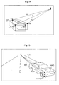
distance determining means 3 is not limited to that illustrated inFig. 2 .Fig. 7 is an explanatory view illustrating a further mode thereof. At the front portions of the opposed lateral sides of thevehicle 20, there are mounted thedistance sensors 3 oriented laterally as the distance determining means. At a front portion of thevehicle 20, there is mounted thecamera 2A oriented forwardly as the image inputting means 2. Thedistance sensor 3 determines a distance to the parkedvehicle 30, in association with movement of thevehicle 20 along the moving direction denoted with the arrow M. That is, in association with movement from a condition (position 7a) shown inFig.7 (a) to a condition (position 7c) shown inFig. 7 (c) , the sensor detects distance information S to a plane of the parkedvehicle 30 along the moving direction of thevehicle 20. InFig. 7 , thecamera 2A is mounted on the side of the moving direction of thevehicle 20. Therefore, unlike the mode illustrated inFig. 2 , thecamera 2A obtains the peripheral image, prior to the detection by thedistance sensor 3. -
Fig. 8 is an explanatory view illustrating a still further mode. At the front portions of the opposed lateral sides of thevehicle 20, there are mounted thedistance sensors 3 oriented laterally as the distance determining means. At the front and rear portions of thevehicle 20, there are mounted thecameras 2A oriented forwardly and rearwardly respectively as the image inputting means 2. Thedistance sensor 3 determines a distance to the parkedvehicle 30, in association with movement of thevehicle 20 along the moving direction denoted with the arrow M. That is, in association with movement from a condition (position 8a) shown inFig.8 (a) to a condition (position 8d) shown inFig. 8 (d) , the sensor detects distance information S to a plane of the parkedvehicle 30 along the moving direction of thevehicle 20. InFig. 8 , thecameras 2A are provided at the two portions, on the moving direction side of thevehicle 20 and on the opposite side thereto. Therefore, prior to the detection by thedistance sensor 3, a peripheral image is obtained by thecamera 2A provided on the moving direction side; and also subsequent to the detection by thedistance sensor 3, a peripheral image is obtained by thecamera 2A provided on the opposite side thereto. - In the modes illustrated in
Figs. 7 and8 , unlike the mode illustrated inFig. 2 , in some cases, the peripheral image is obtained by thecamera 2A, prior to the detection by thedistance sensor 3. As described above, the basic operational principle of the present invention is that thedistance sensors 3 effect "rough" or "approximate" detection and then based on the corner portion C (plane edge) roughly detected, an image recognition processing is effected with using the peripheral image obtained by thecamera 2A. Thus, as shown inFig. 9 , the image inputting means 2 is provided with a temporary storage means 2B for temporarily storing the image captured by thecamera 2A. Then, even when the peripheral image has been obtained prior to the detection of the corner portion C by thedistance sensor 3, the peripheral image may be obtained from the temporary storage means 2B after the detection, so that the image recognition of the corner portion C may be done effectively. - Incidentally, though not shown, on the lateral face of the
vehicle 20, there may be provided anadditional camera 2A oriented toward the similar direction to thedistance sensor 3 and having an angle of view inclusive of the position of the obstacle detected by thedistance sensor 3. - Next, as shown in
Fig. 10 , the present invention will be described in details with taking an example of a construction in which thevehicle 20 travels past by two parked vehicles 30 (30A, 30B) as "obstacles", and detection is made for the two parkedvehicles 30 and a space therebetween. Incidentally, the result of the detection of this construction can be utilized for assisting when thevehicle 20 makes parallel parking. - Information useful in assisting such parallel parking, as shown in
Fig. 11 , includes a first plane LN (longitudinal plane) indicative of the lateral faces of the parkedvehicles vehicle 30B close to thevehicle 20, a second plane LT (lateral plane) indicative of the position of the front edge of the other parkedvehicle 30A far from thevehicle 20, a size of parking space PS, a longitudinal distance (overtaking distance) OD from thevehicle 20 to the parking space PS and a lateral distance (side distance) SD from thevehicle 20 to the first plane LN. - Of the above, the parking space PS can be readily obtained from the second plane LT and the curve shape SS (second plane LT1). The longitudinal distance OD and the lateral distance SD can be readily obtained from the first plane LN and the curve shape SS (second plane LT1). Therefore, the important task for the obstacle detection apparatus of the invention resides in detection of the first plane LN, the curve shape SS and the second plane LT. For instance, if the first plane LN, the curve shape SS and the second plane LT can be obtained as illustrated in
Fig. 12 , then, by displaying these in superimposition with the image obtained by thecamera 2A, effective driving assistance is made possible. - The first plane LN, as described hereinbefore with reference to
Figs. 3 and 4 , can be obtained based on the distance information S obtained by thedistance sensor 3. Therefore, the rest of the important task comprises the image recognition of the curve shape SS and the reconstruction of the second image LT by image recognition. As shown inFig. 11 , in order to reconstruct the second plane LT, it is necessary to image-recognize the front profile FP as the shape characteristics at the corner portion CA of the parkedvehicle 30A. In order to recognize the curve shape SS, it is necessary to image-recognize an occlusion profile OP at the corner portion CB of the parkedvehicle 30B. Next, the image recognitions of the front profile and the occlusion profile will be described. -
Fig. 13 is an explanatory view illustrating a method of calculating the front profile. As shown hereinbefore inFig. 10 , thevehicle 20 travels along the moving direction M past by the parkedvehicle 30A. At the rear portion of thevehicle 20, there is mounted thecamera 2A oriented rearward. The corner portion CA of the parkedvehicle 30A will be included in the view angle of thecamera 2A when thevehicle 20 has passed a border point BP and then will move away with further traveling of thevehicle 20. Thedistance sensor 3 detects the approximate position of the corner portion CA. Therefore, with using a peripheral image past the border point BP, the front profile can be calculated (image -recognized). -
Fig. 14 is an explanatory view for illustrating the epipolar geometry principle which is one typical method for calculating front profile. In the figure, two rectangular solids represent an identical object imaged at two view points of a camera which effects translation. Here, "translation" means a movement of the camera free from any rotational component, so that the properties of the camera remain the same before and after the movement. In the figure, marks (m), (m') represent image points representing an identical point of the solid in the two different images. InFig. 14 , there are shown three points: m'1 through m'3 corresponding respectively to three points: m1 through m3. Lines 11-13 joining each (m) with each (m') corresponding thereto are referred to "epipolar lines" 1. The three epipolar lines intersect at one point, which is defined as the "epipole" (e). This characteristics is called "auto epipolar". Then, by utilizing this characteristics and calculating three-dimensional coordinates from the corresponding points (m, m') obtained from the epipolar geometry, three-dimensional information of an object can be obtained. - The detailed explanation of the above technique is found in e.g. "Computer Vision-Geometry of Vision-) ISBN: 4-399-02363-9", Jun Sato, Corona Publishing Co., Ltd. 1999, May 7, first edition: p.80-103. Therefore, the explanation thereof is omitted herein.
-
Fig. 15 shows an example wherein the epipolar geometry is applied to the parkedvehicle 30A. A moving distance, if short, can be taken approximately as a translating movement, even if the movement of thecamera 2A includes a rotational component due to e.g. a steering of thevehicle 20. Then, in the peripheral image captured by thecamera 2A, epipolar lines (1) are applied to scanning lines (s1). Then, by scan-line matching of corresponding positions on the scanning lines (s1), three-dimensional information is obtained. Here, the three-dimensional information refers to points, breakpoints, rectangles, etc. Then, by combing these information, a second plane LT is reconstructed. Incidentally, use of the epipolar geometry is not absolutely needed. Instead, three-dimensional information can be obtained from perpendicular scanning lines (sl) as illustrated inFig. 16 . -
Fig. 17 is an explanatory view for explaining curve shape recognition with occlusion contour OC, which is a typical technique for calculating the occlusion profile. As described in "Computer Vision-Geometry of Vision-" supra, it is possible to apply the epipolar geometry to a curve. This, however, requires significant calculation workload. Needless to say, the epipolar geometry can be used e.g. when the calculation capacity of the ECU1 is sufficient therefor. In this embodiment, a different method will be described in order to demonstrate the application of the epipolar geometry is not absolutely needed. - First, a two-dimensional occlusion contour OC is extracted from the peripheral image. More particularly, transitions are detected from the peripheral image and there is extracted an occlusion contour OC of portions corresponding to the transitions between the parked
vehicle 30B and the background. As shown inFig. 18 , since the corner portion CB is a curve, the light rays R from thecamera 2A are blocked at a plurality of points of the parkedvehicle 30B for each image. Namely, the points representing the corner portion CB on the two-dimensional occlusion profile comprise a group of points. The three-dimensional occlusion profile is a curve shape, hence, the points representing the corner portion CB differ from each other. The points representing the three-dimensional corner portion CB correspond to those points located on the outermost side present on the two-dimensional occlusion profile OC within the peripheral image. According to the number of three-dimensional rays R tangent to the corner portion CB of the parkedvehicle 30B, there are a plurality of points representing the corner portion CB. The occlusion profile is calculated as an "envelope" of all the rays R, as illustrated inFig. 19 .. - As shown in
Fig. 20 , the corner portion CB as present as a plurality of points are tangent to all of the rays R. Hence, the corner portion can be approximated by an osculating circle EC to all of the rays R. The osculating circle EC is a circle tangent to both the first plane LN and the second plane LT1 perpendicular to the first plane LN. If a curve is drawn to join the osculating circle EC, the first plane LN and the second plane LT via contacts to the first plane LN and the second plane LT, this generates a contour shape CS, which, when interpreted three-dimensionally, provides a curve shape SS. - For the calculations of the front profile and the occlusion profile, extraction of the transitions on the scanning lines (sl) is needed. If this is to be made for the entire peripheral image, the amount of calculation needed therefor will be enormous. However, the use of the
distance sensor 3 can advantageously restrict the image area where the front profile or occlusion profile is to appear, so that the three-dimensional information can be readily obtained in this restricted image area. If thedistance sensor 3 is passing in opposition to obstacles (parked vehicles 30) as shown inFig. 21 , the distance information S will have smooth transition (sections denoted with the mark P). Also, if thedistance sensor 3 is located at a position far from the obstacle and no obstacle is present there, then, the distance information S from thisdistance sensor 3 will overflow (the section denoted with the mark B). Therefore, in either case, in each section, the distance information S is smooth. However, the section I between these two sections shows a sharp change. This section I corresponds substantially to the front or rear corner portion C of the parkedvehicle 30. The position of the corner portion C of the parkedvehicle 30 in the peripheral image is set by the image recognition area setting means 7. That is, this can be set as a region of interest ROI for which the shape characteristics such as the occlusion profile or the front profile is to be recognized. According to the present invention, since the image processing is done using only the peripheral image corresponding to the region of interest, the calculation workload can be alleviated. - In the above, the embodiment of the present invention has been described with using parallel parking as an example. Needless to say, the invention can apply also to a garage parking (angle parking). Further, the obstacle is not limited to a parked vehicle, but can be a variety of objects such as a wall face facing a narrow road, an electric pole near a wall face facing a narrow road, etc.
- As described above, it has become possible to provide an obstacle detection apparatus capable of detecting an obstacle with high precision and high reliability, yet with less amount of calculation, based on an image of periphery of the vehicle and a distance to the object present in the vehicle's periphery.
- The obstacle detection apparatus of the invention can be used in a parking assisting device for a vehicle, a traveling assist device, etc.
-
- [
Fig. 1 ] is a block diagram schematically showing a construction of an obstacle detection apparatus relating to the present invention, - [
Fig. 2 ] is an explanatory view illustrating a case where a distance to a parked vehicle and a peripheral image are obtained in accordance with a movement of a vehicle, - [
Fig. 3 ] is an explanatory view illustrating a case in which a first plane is set and a plane edge is estimated, - [
Fig. 4 ] is a perspective view showing an example of relationship between a parked vehicle and first and second planes, - [
Fig. 5 ] is a perspective view illustrating an example of an image recognition area at a plane edge, - [
Fig. 6 ] is a perspective view illustrating examples of a curve shape of a parked vehicle recognized by image recognition technique in an image recognition area, and a second plane to be constructed, - [
Fig. 7 ] is an explanatory view of Example 1 where a distance to a parked vehicle and a peripheral image are obtained in accordance with a movement of a vehicle, - [
Fig. 8 ] is an explanatory view of Example 2 where a distance to a parked vehicle and a peripheral image are obtained in accordance with a movement of a vehicle, - [
Fig. 9 ] is a block diagram schematically showing a further construction of the obstacle detection apparatus relating to the present invention, - [
Fig. 10 ] is an explanatory view illustrating a case in which in the application of the present invention to parallel parking, a distance to a parked vehicle and a peripheral image are obtained in accordance with a movement of a vehicle, - [
Fig. 11 ] is an explanatory view showing two-dimensionally correlation of detection result of the obstacle detection apparatus of the present invention when applied to parallel parking, - [
Fig. 12 ] is a perspective view showing three-dimensionally result of detection of the obstacle detection apparatus in the case of application of the present invention to parallel parking, - [
Fig. 13 ] is an explanatory view illustrating a method for recognizing shape characteristic (front profile) in order to reconstruct a second plane, - [
Fig. 14 ] is an explanatory view illustrating a principle of calculating front profile with using the epipolar geometry, - [
Fig. 15 ] is an explanatory view illustrating an example of calculating front profile with using epipolar lines as scanning lines, - [
Fig. 16 ] is an explanatory view illustrating calculation of front profile with using perpendicular scanning lines, - [
Fig. 17 ] is an explanatory view illustrating an occlusion contour of a parked vehicle on a peripheral image, - [
Fig. 18 ] is an explanatory view illustrating relationship between a moving vehicle and an occlusion contour, - [
Fig. 19 ] is an explanatory view showing light rays from a camera to points on occlusion contour and an envelope thereof, - [
Fig. 20 ] is an explanatory view of approximation of the envelope shown inFig. 19 by an osculating circle, and - [
Fig. 21 ] is an explanatory view illustrating relationship between characteristics of result of determination by distance determining means relative to presence of an obstacle and image processing. -
- 2A:
- camera, 2B: storage means
- 3:
- distance sensor (distance determining means)
- 4:
- subject-vehicle position specifying means
- 5:
- first plane setting means
- 6:
- plane-edge estimating means
- 7:
- image recognition area setting means
- 8:
- image recognizing means
- 9:
- three-dimensional shape recognizing means
Claims (10)
- An obstacle detection apparatus for detecting an obstacle based on an image of periphery of a vehicle and a distance to an obstacle present in the vehicle's periphery, the apparatus comprising:distance determining means for determining, in association with traveling of the vehicle along a direction, a distance to the obstacle present in a direction perpendicular to the vehicle traveling direction;image inputting means for obtaining a peripheral image having a view angle including the obstacle, in association with the traveling of the vehicle;subject-vehicle position specifying means for sequentially specifying a present position of the vehicle which changes in association the traveling of the vehicle;first-plane setting means for setting, as a first plane and based on said distance and said subject-vehicle position, a face of the obstacle which extends perpendicular to the horizontal plane and extends, at the same time, along the traveling direction of the vehicle;plane-edge estimating means for estimating a plane edge of said first plane relative to the vehicle moving direction, based on said distance and said position of the vehicle;image recognition area setting means for setting, as an image recognition area, an area included in the peripheral image and including said plane edge;image recognizing means for image-recognizing a shape characteristics of the obstacle in the image recognition area from the peripheral image; andthree-dimensional shape recognizing means for recognizing the obstacle three-dimensionally, based on said first plane and result of the image recognition made by said image recognizing means.
- The obstacle detection apparatus according to claim 1, wherein said image recognizing means constructs a second plane perpendicular to both the horizontal plane and the first plane, by effecting the image recognition of the shape characteristics of the obstacle in the image recognition area, and said three-dimensional shape recognizing means recognizes the obstacle three-dimensionally, based on said first plane and said second plane.
- The obstacle detection apparatus according to claim 1, wherein said image recognizing means recognizes a curve shape of the obstacle, by effecting the image recognition of the shape characteristics of the obstacle in the image recognition area, and said three-dimensional shape recognizing means recognizes the obstacle three-dimensionally, based on said first plane and said curve shape.
- The obstacle detection apparatus according to claim 1, wherein 1, wherein two plane edges are to be estimated serially along the vehicle traveling direction;
said image recognizing means constructs the second plane perpendicular to both the horizontal plane and the first plane, by effecting image recognition of the shape characteristics of the obstacle within the image recognition area including one of the two plane edges;
said image recognizing means also recognizes the curve shape of the obstacle by effecting image recognition of the shape characteristics of the obstacle within the image recognition area including the other one of the two plane edges; and
said three-dimensional shape recognizing means recognizes the obstacle three-dimensionally, based on said first plane, said second plane and said curve shape. - The obstacle detection apparatus according to claim 1, wherein in case two obstacles are present along the vehicle moving direction, for a plane edge of the first obstacle and a plane edge of the second obstacle which are estimated serially,
said image recognizing means constructs a second plane perpendicular to both the horizontal plane and the first plane, by effecting image recognition of the shape characteristics of the obstacle within the image recognition area including one plane edge;
said image recognizing means also recognizes the curve shape of the obstacle by effecting image recognition of the shape characteristics of the obstacle within the image recognition area including the other plane edge; and
said three-dimensional shape recognizing means recognizes three-dimensionally, the first obstacle, the second obstacle and a space interposed between the first and second obstacles, based on the first plane, the second plane and the curve shape. - The obstacle detection apparatus according to claim 1, wherein said distance determining means is mounted to a lateral face of the vehicle to be oriented laterally;
said image inputting means is mounted to be oriented toward at least one of the front side and the rear side of the vehicle;
said image inputting means includes temporary storage means for temporarily storing the peripheral image obtained; and
said shape recognizing means effects the image recognition of the shape characteristics from the peripheral image stored in said temporary storage means. - The obstacle detection apparatus according to claim 1, wherein said distance determining means is mounted ahead of the image inputting means in the vehicle moving direction and mounted to a lateral face of the vehicle to be oriented laterally; whereas said image inputting means is mounted to be oriented to the rear side in the vehicle moving direction.
- The obstacle detection apparatus according to claim 1, wherein said image recognizing means detects another vehicle parked in the periphery of the subject vehicle, as said obstacle.
- The obstacle detection apparatus according to claim 8, wherein said image recognizing means recognizes a curve shape of the parked vehicle based on an occlusion contour thereof.
- The obstacle detection apparatus according to claim 9, wherein said image recognizing means recognizes a corner portion of the parked vehicle.
Applications Claiming Priority (2)
| Application Number | Priority Date | Filing Date | Title |
|---|---|---|---|
| JP2005186843A JP4600760B2 (en) | 2005-06-27 | 2005-06-27 | Obstacle detection device |
| PCT/JP2006/310784 WO2007000868A1 (en) | 2005-06-27 | 2006-05-30 | Obstacle detection device |
Publications (3)
| Publication Number | Publication Date |
|---|---|
| EP1927962A1 true EP1927962A1 (en) | 2008-06-04 |
| EP1927962A4 EP1927962A4 (en) | 2011-08-10 |
| EP1927962B1 EP1927962B1 (en) | 2018-10-17 |
Family
ID=37595124
Family Applications (1)
| Application Number | Title | Priority Date | Filing Date |
|---|---|---|---|
| EP06747012.0A Expired - Fee Related EP1927962B1 (en) | 2005-06-27 | 2006-05-30 | Obstacle detection device |
Country Status (4)
| Country | Link |
|---|---|
| US (1) | US7894631B2 (en) |
| EP (1) | EP1927962B1 (en) |
| JP (1) | JP4600760B2 (en) |
| WO (1) | WO2007000868A1 (en) |
Cited By (3)
| Publication number | Priority date | Publication date | Assignee | Title |
|---|---|---|---|---|
| EP2557020A3 (en) * | 2011-08-12 | 2013-09-25 | Robert Bosch Gmbh | Method to support a driver when parking |
| EP2726315B1 (en) * | 2011-06-28 | 2016-03-02 | Volkswagen Aktiengesellschaft | Method and device for parking a vehicle |
| CN107850902A (en) * | 2015-07-08 | 2018-03-27 | 深圳市大疆创新科技有限公司 | Camera configuration in loose impediment |
Families Citing this family (52)
| Publication number | Priority date | Publication date | Assignee | Title |
|---|---|---|---|---|
| JP2007161190A (en) * | 2005-12-16 | 2007-06-28 | Toyota Motor Corp | Electrically-driven vehicle |
| DE102006052779A1 (en) * | 2006-11-09 | 2008-05-15 | Bayerische Motoren Werke Ag | Method for generating an overall image of the surroundings of a motor vehicle |
| EP2026246A1 (en) * | 2007-08-03 | 2009-02-18 | Harman/Becker Automotive Systems GmbH | Method and apparatus for evaluating an image |
| FR2922029A1 (en) * | 2007-10-08 | 2009-04-10 | Imra Europ Sas Soc Par Actions | Detector for e.g. car, has controller for detecting geographic end point and determining position of point in spatial reference from transition zone images, where point is associated to end contour of object at transition zone |
| KR101104609B1 (en) * | 2007-10-26 | 2012-01-12 | 주식회사 만도 | Method and System for Recognizing Target Parking Location |
| CN101470806B (en) * | 2007-12-27 | 2012-06-27 | 东软集团股份有限公司 | Vehicle lamp detection method and apparatus, interested region splitting method and apparatus |
| DE102008004632A1 (en) * | 2008-01-16 | 2009-07-23 | Robert Bosch Gmbh | Device and method for measuring a parking space |
| JP5083079B2 (en) * | 2008-07-11 | 2012-11-28 | 日産自動車株式会社 | Parking assistance device and parking assistance method |
| JP5500369B2 (en) * | 2009-08-03 | 2014-05-21 | アイシン精機株式会社 | Vehicle peripheral image generation device |
| FR2950451B1 (en) * | 2009-09-18 | 2011-11-04 | Imra Europ Sas | ALGORITHM FOR DETECTION OF CONTOUR POINTS IN AN IMAGE |
| US20110068953A1 (en) * | 2009-09-24 | 2011-03-24 | Salvador Toledo | Vehicle Park Assist System and Method for Parking a Vehicle Using Such System |
| WO2011145141A1 (en) * | 2010-05-19 | 2011-11-24 | 三菱電機株式会社 | Vehicle rear-view observation device |
| CA2741510A1 (en) * | 2010-05-26 | 2011-11-26 | James H. Lacey | Door mountable camera surveillance device and method |
| US9064293B2 (en) * | 2010-06-15 | 2015-06-23 | Mitsubishi Electric Corporation | Vehicle surroundings monitoring device |
| US10109065B2 (en) | 2011-01-25 | 2018-10-23 | Qualcomm Incorporated | Using occlusions to detect and track three-dimensional objects |
| WO2012143952A2 (en) * | 2011-04-20 | 2012-10-26 | B Amutha | A system and apparatus for safe remote on-line tracing, shadowing, surveillance, inter-communication, location, navigation, tagging, rescue, recovery and restitution of humans and stolen/missing chattels, and the method/s thereof |
| WO2012168322A2 (en) | 2011-06-06 | 2012-12-13 | 3Shape A/S | Dual-resolution 3d scanner |
| JP5682788B2 (en) * | 2011-09-27 | 2015-03-11 | アイシン精機株式会社 | Vehicle periphery monitoring device |
| DE102012201495A1 (en) * | 2012-02-02 | 2013-08-08 | Robert Bosch Gmbh | Automatic selection of the target position in a parking space by combined evaluation of video / USS objects |
| WO2014017104A1 (en) * | 2012-07-27 | 2014-01-30 | 京セラ株式会社 | Image processing device, image pickup device, mobile unit, program and region setting method |
| JP5918689B2 (en) * | 2012-12-14 | 2016-05-18 | 株式会社日本自動車部品総合研究所 | Parking assistance device |
| US9076257B2 (en) | 2013-01-03 | 2015-07-07 | Qualcomm Incorporated | Rendering augmented reality based on foreground object |
| DE102013202915A1 (en) * | 2013-02-22 | 2014-08-28 | Robert Bosch Gmbh | Method for measuring parking space for parking assistance system of motor vehicle, involves determining free parking area within parking space depending on positions of two corners and detection of obstacles within two blind ranges |
| JP5975172B2 (en) * | 2013-04-26 | 2016-08-23 | トヨタ自動車株式会社 | Parking assistance device |
| US9250324B2 (en) | 2013-05-23 | 2016-02-02 | GM Global Technology Operations LLC | Probabilistic target selection and threat assessment method and application to intersection collision alert system |
| US8923565B1 (en) * | 2013-09-26 | 2014-12-30 | Chengdu Haicun Ip Technology Llc | Parked vehicle detection based on edge detection |
| JP6214995B2 (en) * | 2013-10-11 | 2017-10-18 | 株式会社東芝 | Parked vehicle detection device, vehicle management system, control method, and control program |
| US9342747B2 (en) * | 2014-04-14 | 2016-05-17 | Bendix Commercial Vehicle Systems Llc | Vehicle driver assistance apparatus for assisting a vehicle driver in maneuvering the vehicle relative to an object |
| KR101637716B1 (en) * | 2014-11-03 | 2016-07-07 | 현대자동차주식회사 | Apparatus and method for recognizing position of obstacle in vehicle |
| US20160176340A1 (en) * | 2014-12-17 | 2016-06-23 | Continental Automotive Systems, Inc. | Perspective shifting parking camera system |
| US10551498B2 (en) | 2015-05-21 | 2020-02-04 | Navico Holding As | Wireless sonar device |
| WO2016205938A1 (en) * | 2015-06-22 | 2016-12-29 | Appetite Lab Inc. | Devices and methods for locating and visualizing underwater objects |
| US10578706B2 (en) | 2015-08-06 | 2020-03-03 | Navico Holding As | Wireless sonar receiver |
| US10635909B2 (en) * | 2015-12-30 | 2020-04-28 | Texas Instruments Incorporated | Vehicle control with efficient iterative triangulation |
| US10325502B2 (en) * | 2016-02-10 | 2019-06-18 | Ford Global Technologies, Llc | Parallel parking assistant |
| US9975480B2 (en) | 2016-04-12 | 2018-05-22 | Denso International America, Inc. | Methods and systems for blind spot monitoring with adaptive alert zone |
| US9931981B2 (en) * | 2016-04-12 | 2018-04-03 | Denso International America, Inc. | Methods and systems for blind spot monitoring with rotatable blind spot sensor |
| US9947226B2 (en) | 2016-04-12 | 2018-04-17 | Denso International America, Inc. | Methods and systems for blind spot monitoring with dynamic detection range |
| US9994151B2 (en) | 2016-04-12 | 2018-06-12 | Denso International America, Inc. | Methods and systems for blind spot monitoring with adaptive alert zone |
| US10789850B2 (en) * | 2016-05-10 | 2020-09-29 | Mitsubishi Electric Corporation | Obstacle detection device, driving assistance system, and obstacle detection method |
| US10719077B2 (en) | 2016-10-13 | 2020-07-21 | Navico Holding As | Castable sonar devices and operations in a marine environment |
| WO2018105417A1 (en) * | 2016-12-09 | 2018-06-14 | 京セラ株式会社 | Imaging device, image processing device, display system, and vehicle |
| JP6673293B2 (en) * | 2017-05-24 | 2020-03-25 | トヨタ自動車株式会社 | Vehicle system |
| US20190339362A1 (en) * | 2018-05-03 | 2019-11-07 | Mediatek Inc. | Signature-based object detection method and associated apparatus |
| WO2019215789A1 (en) * | 2018-05-07 | 2019-11-14 | 三菱電機株式会社 | Parking assistance device |
| FR3084628B1 (en) * | 2018-07-31 | 2021-06-11 | Renault Sas | METHOD OF DETERMINING A TYPE OF PARKING SPACE |
| CN110826357B (en) * | 2018-08-07 | 2022-07-26 | 北京市商汤科技开发有限公司 | Method, device, medium and equipment for three-dimensional detection and intelligent driving control of object |
| US11170299B2 (en) | 2018-12-28 | 2021-11-09 | Nvidia Corporation | Distance estimation to objects and free-space boundaries in autonomous machine applications |
| US11182916B2 (en) * | 2018-12-28 | 2021-11-23 | Nvidia Corporation | Distance to obstacle detection in autonomous machine applications |
| CN109993060B (en) * | 2019-03-01 | 2022-11-22 | 长安大学 | Vehicle omnidirectional obstacle detection method of depth camera |
| JP7465726B2 (en) * | 2020-05-28 | 2024-04-11 | フォルシアクラリオン・エレクトロニクス株式会社 | Parking assistance device and method for controlling parking assistance device |
| JP2023165550A (en) * | 2022-05-06 | 2023-11-16 | 京セラ株式会社 | Information processing device |
Citations (4)
| Publication number | Priority date | Publication date | Assignee | Title |
|---|---|---|---|---|
| US6483429B1 (en) * | 1999-10-21 | 2002-11-19 | Matsushita Electric Industrial Co., Ltd. | Parking assistance system |
| US20030060972A1 (en) * | 2001-08-28 | 2003-03-27 | Toshiaki Kakinami | Drive assist device |
| DE10244148A1 (en) * | 2002-09-23 | 2004-04-08 | Daimlerchrysler Ag | Method and device for video-based observation and measurement of the lateral surroundings of a vehicle |
| EP1462762A1 (en) * | 2003-03-25 | 2004-09-29 | Aisin Seiki Kabushiki Kaisha | Circumstance monitoring device of a vehicle |
Family Cites Families (11)
| Publication number | Priority date | Publication date | Assignee | Title |
|---|---|---|---|---|
| JP3167752B2 (en) | 1991-10-22 | 2001-05-21 | 富士重工業株式会社 | Vehicle distance detection device |
| JP2001315603A (en) * | 2000-05-09 | 2001-11-13 | Matsushita Electric Ind Co Ltd | Drive supporting device |
| JP3750512B2 (en) * | 2000-10-12 | 2006-03-01 | 日産自動車株式会社 | Vehicle obstacle detection device |
| JP2002170103A (en) | 2000-12-01 | 2002-06-14 | Nissan Motor Co Ltd | Parking space map creating device and display device |
| JP2003132349A (en) * | 2001-10-24 | 2003-05-09 | Matsushita Electric Ind Co Ltd | Drawing device |
| JP4010224B2 (en) | 2002-10-23 | 2007-11-21 | トヨタ自動車株式会社 | Vehicle periphery monitoring device |
| JP4092479B2 (en) * | 2003-01-07 | 2008-05-28 | 日産自動車株式会社 | Vehicle driving support device |
| JPWO2004083889A1 (en) * | 2003-03-20 | 2006-06-22 | 松下電器産業株式会社 | Obstacle detection device |
| JP4402400B2 (en) * | 2003-08-28 | 2010-01-20 | オリンパス株式会社 | Object recognition device |
| JP4277081B2 (en) * | 2004-03-17 | 2009-06-10 | 株式会社デンソー | Driving assistance device |
| JP4179285B2 (en) * | 2005-01-12 | 2008-11-12 | トヨタ自動車株式会社 | Parking assistance device |
-
2005
- 2005-06-27 JP JP2005186843A patent/JP4600760B2/en not_active Expired - Fee Related
-
2006
- 2006-05-30 EP EP06747012.0A patent/EP1927962B1/en not_active Expired - Fee Related
- 2006-05-30 WO PCT/JP2006/310784 patent/WO2007000868A1/en active Application Filing
- 2006-05-30 US US11/993,104 patent/US7894631B2/en not_active Expired - Fee Related
Patent Citations (4)
| Publication number | Priority date | Publication date | Assignee | Title |
|---|---|---|---|---|
| US6483429B1 (en) * | 1999-10-21 | 2002-11-19 | Matsushita Electric Industrial Co., Ltd. | Parking assistance system |
| US20030060972A1 (en) * | 2001-08-28 | 2003-03-27 | Toshiaki Kakinami | Drive assist device |
| DE10244148A1 (en) * | 2002-09-23 | 2004-04-08 | Daimlerchrysler Ag | Method and device for video-based observation and measurement of the lateral surroundings of a vehicle |
| EP1462762A1 (en) * | 2003-03-25 | 2004-09-29 | Aisin Seiki Kabushiki Kaisha | Circumstance monitoring device of a vehicle |
Non-Patent Citations (6)
| Title |
|---|
| DONGJIN HAN ET AL: "Vehicle Class Recognition from Video-Based on 3D Curve Probes", VISUAL SURVEILLANCE AND PERFORMANCE EVALUATION OF TRACKING AND SURVEIL LANCE, 2005. 2ND JOINT IEEE INTERNATIONAL WORKSHOP ON BEIJING, CHINA 15-16 OCT. 2005, PISCATAWAY, NJ, USA,IEEE, 15 October 2005 (2005-10-15), pages 285-292, XP010875293, DOI: DOI:10.1109/VSPETS.2005.1570927 ISBN: 978-0-7803-9424-7 * |
| FINTZEL K ET AL: "3D vision system for vehicles", INTELLIGENT VEHICLES SYMPOSIUM, 2003. PROCEEDINGS. IEEE JUNE 9-11, 2003, PISCATAWAY, NJ, USA,IEEE, 9 June 2003 (2003-06-09), pages 174-179, XP010645870, ISBN: 978-0-7803-7848-3 * |
| HIRAHARA K ET AL: "Detection of street-parking vehicles from panoramic street image", INTELLIGENT TRANSPORTATION SYSTEMS, 2003. PROCEEDINGS. 2003 IEEE OCT. 12-15, 2003, PISCATAWAY, NJ, USA,IEEE, vol. 2, 12 October 2003 (2003-10-12), pages 993-998, XP010672868, DOI: DOI:10.1109/ITSC.2003.1252635 ISBN: 978-0-7803-8125-4 * |
| Ichiro Masaki: "Vision-based Vehicle Guidance", 1 January 1992 (1992-01-01), Springer, XP002646184, pages 204-221, * page 207, line 25 - page 209, line 4; figures 9.1, 9.2 * * |
| K. Aizawa, K. Sakaue and Y. Suenaga: "Image Processing Technologies: Algorithms, Sensors, and Applications", 1 January 2004 (2004-01-01), Marcel Dekker, XP8138690, pages 1-26, * page 5, paragraph 1 - paragraph 2 * * page 7 * * page 11, paragraph 2 - page 13, last paragraph * * |
| See also references of WO2007000868A1 * |
Cited By (3)
| Publication number | Priority date | Publication date | Assignee | Title |
|---|---|---|---|---|
| EP2726315B1 (en) * | 2011-06-28 | 2016-03-02 | Volkswagen Aktiengesellschaft | Method and device for parking a vehicle |
| EP2557020A3 (en) * | 2011-08-12 | 2013-09-25 | Robert Bosch Gmbh | Method to support a driver when parking |
| CN107850902A (en) * | 2015-07-08 | 2018-03-27 | 深圳市大疆创新科技有限公司 | Camera configuration in loose impediment |
Also Published As
| Publication number | Publication date |
|---|---|
| EP1927962B1 (en) | 2018-10-17 |
| EP1927962A4 (en) | 2011-08-10 |
| JP2007004697A (en) | 2007-01-11 |
| US20100045448A1 (en) | 2010-02-25 |
| WO2007000868A1 (en) | 2007-01-04 |
| US7894631B2 (en) | 2011-02-22 |
| JP4600760B2 (en) | 2010-12-15 |
Similar Documents
| Publication | Publication Date | Title |
|---|---|---|
| US7894631B2 (en) | Obstacle detection apparatus | |
| JP6724425B2 (en) | Parking assistance device | |
| EP2093129B1 (en) | Parking assist apparatus and method | |
| CN107792061B (en) | Parking assist apparatus | |
| EP1094337B1 (en) | Parking assistance system | |
| JP3719095B2 (en) | Behavior detection apparatus and gradient detection method | |
| CN109219546B (en) | Parking assistance device and parking assistance method | |
| US20080140286A1 (en) | Parking Trace Recognition Apparatus and Automatic Parking System | |
| JP2013541915A (en) | Blind Spot Zone Display Device and Method | |
| JP2003063340A (en) | Drive auxiliary device | |
| EP3708466B1 (en) | Parking assistance device and parking assistance method | |
| KR20080109871A (en) | Parking assistance device and parking assistance method | |
| JP2006273122A (en) | Parking brake assistance device | |
| JP6337811B2 (en) | Image processing apparatus and image processing method | |
| JP2012066709A (en) | Parking assist system | |
| JP2017147629A (en) | Parking position detection system, and automatic parking system using the same | |
| JP2012176656A (en) | Parking support device | |
| JP2004120661A (en) | Moving object periphery monitoring apparatus | |
| KR101190789B1 (en) | Apparatus and method for measurementing distance of vehicle | |
| JP2003036500A (en) | Device for recognizing travel division line of vehicle | |
| JP4207519B2 (en) | Moving object periphery monitoring device | |
| CN108297794B (en) | Parking assistance device and travel prediction line display method | |
| US20220237923A1 (en) | Object detection device, object detection method, and storage medium | |
| JP7380058B2 (en) | parking assist device | |
| JP7318377B2 (en) | Object detection device |
Legal Events
| Date | Code | Title | Description |
|---|---|---|---|
| PUAI | Public reference made under article 153(3) epc to a published international application that has entered the european phase |
Free format text: ORIGINAL CODE: 0009012 |
|
| 17P | Request for examination filed |
Effective date: 20071221 |
|
| AK | Designated contracting states |
Kind code of ref document: A1 Designated state(s): DE FR |
|
| RIN1 | Information on inventor provided before grant (corrected) |
Inventor name: KAKINAMI, TOSHIAKI,C/O INTELLECTUAL PROPERTY DEPAR |
|
| RIN1 | Information on inventor provided before grant (corrected) |
Inventor name: KAKINAMI, TOSHIAKI,C/O INTELLECTUAL PROPERTY DEPAR |
|
| DAX | Request for extension of the european patent (deleted) | ||
| RBV | Designated contracting states (corrected) |
Designated state(s): DE FR |
|
| RBV | Designated contracting states (corrected) |
Designated state(s): DE FR |
|
| RIC1 | Information provided on ipc code assigned before grant |
Ipc: G06T 1/00 20060101ALI20110630BHEP Ipc: B60R 21/00 20060101ALI20110630BHEP Ipc: H04N 7/18 20060101ALI20110630BHEP Ipc: G06T 7/00 20060101ALI20110630BHEP Ipc: B62D 15/02 20060101ALN20110630BHEP Ipc: G06K 9/32 20060101ALI20110630BHEP Ipc: G06K 9/00 20060101AFI20110630BHEP Ipc: G08G 1/16 20060101ALI20110630BHEP |
|
| A4 | Supplementary search report drawn up and despatched |
Effective date: 20110708 |
|
| 17Q | First examination report despatched |
Effective date: 20141125 |
|
| REG | Reference to a national code |
Ref country code: DE Ref legal event code: R079 Ref document number: 602006056605 Country of ref document: DE Free format text: PREVIOUS MAIN CLASS: G08G0001160000 Ipc: G06K0009000000 |
|
| GRAP | Despatch of communication of intention to grant a patent |
Free format text: ORIGINAL CODE: EPIDOSNIGR1 |
|
| RIC1 | Information provided on ipc code assigned before grant |
Ipc: G06K 9/00 20060101AFI20180416BHEP Ipc: B62D 15/02 20060101ALN20180416BHEP Ipc: B60R 21/00 20060101ALI20180416BHEP Ipc: G06K 9/32 20060101ALI20180416BHEP Ipc: G06T 7/00 20060101ALI20180416BHEP |
|
| INTG | Intention to grant announced |
Effective date: 20180504 |
|
| GRAS | Grant fee paid |
Free format text: ORIGINAL CODE: EPIDOSNIGR3 |
|
| GRAA | (expected) grant |
Free format text: ORIGINAL CODE: 0009210 |
|
| AK | Designated contracting states |
Kind code of ref document: B1 Designated state(s): DE FR |
|
| REG | Reference to a national code |
Ref country code: DE Ref legal event code: R096 Ref document number: 602006056605 Country of ref document: DE |
|
| REG | Reference to a national code |
Ref country code: DE Ref legal event code: R097 Ref document number: 602006056605 Country of ref document: DE |
|
| PLBE | No opposition filed within time limit |
Free format text: ORIGINAL CODE: 0009261 |
|
| STAA | Information on the status of an ep patent application or granted ep patent |
Free format text: STATUS: NO OPPOSITION FILED WITHIN TIME LIMIT |
|
| 26N | No opposition filed |
Effective date: 20190718 |
|
| REG | Reference to a national code |
Ref country code: DE Ref legal event code: R084 Ref document number: 602006056605 Country of ref document: DE |
|
| PGFP | Annual fee paid to national office [announced via postgrant information from national office to epo] |
Ref country code: DE Payment date: 20200519 Year of fee payment: 15 Ref country code: FR Payment date: 20200414 Year of fee payment: 15 |
|
| REG | Reference to a national code |
Ref country code: DE Ref legal event code: R079 Ref document number: 602006056605 Country of ref document: DE Free format text: PREVIOUS MAIN CLASS: G06K0009000000 Ipc: G06V0010000000 |
|
| REG | Reference to a national code |
Ref country code: DE Ref legal event code: R119 Ref document number: 602006056605 Country of ref document: DE |
|
| PG25 | Lapsed in a contracting state [announced via postgrant information from national office to epo] |
Ref country code: DE Free format text: LAPSE BECAUSE OF NON-PAYMENT OF DUE FEES Effective date: 20211201 |
|
| PG25 | Lapsed in a contracting state [announced via postgrant information from national office to epo] |
Ref country code: FR Free format text: LAPSE BECAUSE OF NON-PAYMENT OF DUE FEES Effective date: 20210531 |