EP1927900A2 - Fixing device used for image forming device - Google Patents
Fixing device used for image forming device Download PDFInfo
- Publication number
- EP1927900A2 EP1927900A2 EP07023090A EP07023090A EP1927900A2 EP 1927900 A2 EP1927900 A2 EP 1927900A2 EP 07023090 A EP07023090 A EP 07023090A EP 07023090 A EP07023090 A EP 07023090A EP 1927900 A2 EP1927900 A2 EP 1927900A2
- Authority
- EP
- European Patent Office
- Prior art keywords
- fixing device
- guide member
- frame
- heating roller
- roller
- Prior art date
- Legal status (The legal status is an assumption and is not a legal conclusion. Google has not performed a legal analysis and makes no representation as to the accuracy of the status listed.)
- Granted
Links
Images




Classifications
-
- G—PHYSICS
- G03—PHOTOGRAPHY; CINEMATOGRAPHY; ANALOGOUS TECHNIQUES USING WAVES OTHER THAN OPTICAL WAVES; ELECTROGRAPHY; HOLOGRAPHY
- G03G—ELECTROGRAPHY; ELECTROPHOTOGRAPHY; MAGNETOGRAPHY
- G03G15/00—Apparatus for electrographic processes using a charge pattern
- G03G15/70—Detecting malfunctions relating to paper handling, e.g. jams
-
- G—PHYSICS
- G03—PHOTOGRAPHY; CINEMATOGRAPHY; ANALOGOUS TECHNIQUES USING WAVES OTHER THAN OPTICAL WAVES; ELECTROGRAPHY; HOLOGRAPHY
- G03G—ELECTROGRAPHY; ELECTROPHOTOGRAPHY; MAGNETOGRAPHY
- G03G15/00—Apparatus for electrographic processes using a charge pattern
- G03G15/20—Apparatus for electrographic processes using a charge pattern for fixing, e.g. by using heat
- G03G15/2003—Apparatus for electrographic processes using a charge pattern for fixing, e.g. by using heat using heat
- G03G15/2014—Apparatus for electrographic processes using a charge pattern for fixing, e.g. by using heat using heat using contact heat
- G03G15/2017—Structural details of the fixing unit in general, e.g. cooling means, heat shielding means
- G03G15/2028—Structural details of the fixing unit in general, e.g. cooling means, heat shielding means with means for handling the copy material in the fixing nip, e.g. introduction guides, stripping means
-
- G—PHYSICS
- G03—PHOTOGRAPHY; CINEMATOGRAPHY; ANALOGOUS TECHNIQUES USING WAVES OTHER THAN OPTICAL WAVES; ELECTROGRAPHY; HOLOGRAPHY
- G03G—ELECTROGRAPHY; ELECTROPHOTOGRAPHY; MAGNETOGRAPHY
- G03G2215/00—Apparatus for electrophotographic processes
- G03G2215/00362—Apparatus for electrophotographic processes relating to the copy medium handling
- G03G2215/00535—Stable handling of copy medium
- G03G2215/00548—Jam, error detection, e.g. double feeding
-
- G—PHYSICS
- G03—PHOTOGRAPHY; CINEMATOGRAPHY; ANALOGOUS TECHNIQUES USING WAVES OTHER THAN OPTICAL WAVES; ELECTROGRAPHY; HOLOGRAPHY
- G03G—ELECTROGRAPHY; ELECTROPHOTOGRAPHY; MAGNETOGRAPHY
- G03G2221/00—Processes not provided for by group G03G2215/00, e.g. cleaning or residual charge elimination
- G03G2221/16—Mechanical means for facilitating the maintenance of the apparatus, e.g. modular arrangements and complete machine concepts
- G03G2221/1672—Paper handling
- G03G2221/1675—Paper handling jam treatment
Definitions
- the present invention relates to a fixing device for thermally fixing an image onto a recording sheet, and an image forming device provided with such a fixing device.
- a well-known fixing device used for an image forming device includes a heating roller heated by an internal heat source, a press roller for holding a recording sheet together with the heating roller, and a peeling claw facing the heating roller to peel off the recording sheet from the heating roller.
- the fixing device feeds the recording sheet onto which a toner image has been transferred, holding the recording sheet between the heating roller and the press roller, to thermally fix the toner image onto the recording sheet.
- the peeling claw is used to peel off the recording sheet from the surface of the heating roller.
- Japanese Patent Application Publication S61-200564 discloses a peeling device in which the leading edge of the peeling claw is displaceably supported to the frame to remove away from the heating roller when the peeling claw is pressed by the jammed recording sheet. According to this configuration, even if the peeling claw is pressed by the jammed recording sheet, the leading edge of the peeling claw is moved away from the heating roller, thereby preventing any damage of the heating roller.
- the leading edge of the peeling claw is not always moved away from the heating roller, depending on the posture and/or the number of the recording sheets jammed near the peeling claw. In this case, the leading edge of the peeling claw may be forced to strongly press the heating roller, thereby causing damage thereto.
- an object of the present invention is to provide a fixing device which reliably prevents damage of the heating roller which may caused by the jammed recording paper jam.
- the present invention provides a fixing device having a frame, a heating roller, a press roller, a peeler, a guide member, a first bias unit, and a wheel.
- the heating roller is provided to the frame to produce heat, the heating roller having a roller rotation axis and a cylindrical surface.
- the press roller is pressed against the cylindrical surface to feed a recording medium together with the heating roller along a feeding path.
- the peeler is provided to the frame having a peeling surface having a leading edge. The leading edge faces the cylindrical surface to peel off the recording medium on the cylindrical surface.
- the peeling surface faces the feeding path.
- the guide member is positioned facing the peeling surface to guide the recording medium which has passed through between the heating roller and the press roller to downstream of the feeding path.
- the guide member is movable between a near position and a far position, the near position being closer to the peeling surface than the far position.
- the first bias unit biases the guide member to the near position.
- the wheel is supported to the frame and having a wheel rotation axis and a circumferential edge.
- the wheel rotation axis is parallel to the roller rotation axis.
- the wheel is positioned in a manner that a part of the circumferential edge protrudes from the peeling surface to the guiding member in a virtual plane perpendicular to the wheel rotation axis.
- the present invention provides a fixing device having a frame, a heating roller, a press roller, a peeler, a guide member, a first bias unit, and a rotation member.
- the heating roller is provided to the frame to produce heat.
- the heating roller has a roller rotation axis and a cylindrical surface.
- the press roller is pressed against the cylindrical surface to feed a recording medium together with the heating roller along a feeding path.
- the peeler is provided to the frame and having a peeling surface having a leading edge, the leading edge facing the cylindrical surface to peel off the recording medium on the cylindrical surface.
- the peeling surface faces the feeding path.
- the guide member is positioned facing the peeling surface to guide the recording medium which has passed through between the heating roller and the press roller to downstream of the feeding path.
- the guide member is movable between a near position and a far position.
- the near position is closer to the peeling surface than the far position.
- the first bias unit biases the guide member to the near position.
- the rotation member is supported to the frame and has a rotation axis and an outer circumference.
- the rotation axis is parallel to the roller rotation axis.
- the rotation member is positioned in a manner that a part of the outer circumference protrudes from the peeling surface to the guiding member in a virtual plane perpendicular to the wheel rotation axis.
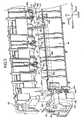
- FIG. 1 is a side cross-sectional view showing a laser printer having a fixing device according to the present invention
- FIG. 2 is a side view showing the fixing device
- FIG. 3 is a perspective view of the fixing device
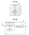
- FIG. 4A is a block diagram of a controller
- FIG. 4B is a block diagram of a determination unit
- FIG. 5 is a flowchart showing a processing performed by the determination unit
- FIG. 6 is a side view showing the fixing device when a paper jam occurs
- FIG. 7 is a side view showing the fixing device when the different type of the paper jam from that of FIG. 6 occurs;
- FIG. 8 is a perspective view showing a relationship between an optical sensor, a guide member, and a detection lever.
- FIG. 9 is a side view showing another embodiment of the fixing device.
- FIG. 1 shows a laser printer 1 having a sheet supply section 4 and an image forming section 5 in a main body casing 2.
- the sheet supply section 4 functions to supply a sheet 3, and has a sheet supply tray 11 detachably attached to the bottom portion inside the main body casing 2 and a sheet pressing plate 12 provided in the sheet supply tray 11.
- the sheet supply section 4 further has a sheet supply roller 13 and a sheet supply pad 14 which are provided in the upper portion of one end side of the sheet supply tray 11, and paper powder removing rollers 15, 16 provided on the downstream side relative to the sheet supply roller 13 in the feeding direction of the sheet 3.
- the sheet supply section 4 further has resist rollers 17, 17 provided on the downstream side relative to the paper powder removing rollers 15 and 16 in the sheet feeding direction.
- the recording sheets 3 stacked in the sheet supply tray 11 are pressed to the sheet supply roller 13 by the sheet pressing plate 12, fed one by one by the sheet supply roller 13 and sheet supply pad 14, and finally supplied to the image forming section 5 by the rollers 13-16.
- the image forming section 5 has a scanning unit 20, a process cartridge 30, and a fixing device 40 for forming an image onto the supplied sheet 3.
- the scanner section 20 is provided at the upper portion inside the main body casing 2 and has a laser beam source (not shown), a rotatable polygon mirror 21, lenses 22, 23, and reflection mirrors 24, 25, and 26.
- a laser beam which is emitted from the laser beam source based on image data passes through the polygon mirror 21, the lens 22, the reflection mirrors 24, 25, the lens 23, and the reflection mirror 26 in the order mentioned and impinges on the surface of a photoconductive drum 33 in the process cartridge 30 through a high speed scanning process.
- the process cartridge 30 is provided below the scanner section 20 and detachably attached to the main body casing 2.
- the process cartridge 30 includes a developer cartridge 32, the photoconductive drum 33, a scorotron charger 34, and a transfer roller 35 within a hollow casing 31.
- the developer cartridge 32 is detachably attached to the casing 31 and has a developing roller 36, a layer thickness regulation blade 37, a supply roller 38, and a toner hopper 39.
- Toner in the toner hopper 39 is supplied to the developing roller 36 by the rotation of the supply roller 38 in the direction of an arrow (counterclockwise direction).
- the toner is frictionally charged positively between the supply roller 38 and the developing roller 36.
- the toner supplied on the developing roller 36 enters between the layer thickness regulation blade 37 and the developing roller 36 by the rotation of the developing roller 36 in the direction of an arrow (counterclockwise direction).
- the toner is then carried on the developing roller 36 to form a thin layer having a constant thickness.
- the photoconductive drum 33 is supported to the casing 31 to rotate in the direction of an arrow (clockwise direction).
- the main body of the photoconductive drum 33 is grounded.
- the surface of the photoconductive drum 33 is formed from a positively charged photosensitive layer.
- the scorotron charger 34 is disposed above the photoconductive drum 33 to face the photoconductive drum 33 separated therefrom by a given distance.
- the scorotron charger 34 is a charger for generating corona discharge from a charging wire of tungsten for positive charge and positively charging the surface of the photoconductive drum 33 uniformly.
- the transfer roller 35 is disposed below the photoconductive drum 33 so as to face the photoconductive drum 33 in a contact manner with the photoconductive drum 33 and supported by the casing 31 so as to rotate in the direction of an arrow (counterclockwise direction).
- the transfer roller 35 has a roller shaft made of metal and a roller surface formed of electrically conductive rubber material that covers around the roller shaft. A transfer bias voltage is applied to the transfer roller 35 during a transfer process.
- the surface of the photoconductive drum 33 is positively charged uniformly by the scorotron charger 34, and then is exposed to the laser beam by the high-speed scanning process from the scanner section 20. As a result, the potential of the exposed portion is decreased to form an electrostatic latent image based on image data.
- the "electrostatic latent image” refers to the area exposed by the laser beam and having a lowered electric potential in the surface of the photoconductive drum 33 that has been positively charged uniformly.
- the photoconductive drum 33 and transfer roller 35 are rotatably driven so as to hold the sheet 3 for feeding.
- the toner image carried on the surface of the photoconductive drum 33 is transferred onto the sheet 3 while the sheet 3 passes between the photoconductive drum 33 and the transfer roller 35.
- the fixing device 40 is disposed on the sheet feeding direction on the downstream side relative to the process cartridge 30.
- the fixing device 40 has a heating roller 41, a press roller 42, a peeling claw 43, and a guide member 44 in a frame 45.
- the press roller 42 is disposed contacting with the heating roller 41 to hold the sheet 3 between the heating roller 41 and the press roller 42.
- the peeling claw 43 peels off the sheet 3 on the heating roller 41.
- the guide member 44 is provided on the downstream side relative to the heating roller 41 and press roller 42 in the sheet feeding direction.
- the heating roller 41 is formed of a metal tube having a cylindrical surface 41b coated with a fluorine resin.
- the heating roller 41 includes a heater 41a made of a halogen lamp.
- the heating roller 41 is heated by the heater 41a.
- the heating roller 41 is rotated about a roller axis which is co-axial with the heater 41a.
- the heating roller 41 provides heat to the sheet 3 though the cylindrical surface 41b.
- the press roller 42 is disposed below the heating roller 41 so as to face the heating roller 41 for pressing the cylindrical surface of the heating roller 41 using a biasing unit (not shown).
- the press roller 42 has a roller shaft 42a made of metal and a roller formed of a rubber material covering around the roller shaft. The press roller 42 is rotated, following the rotation of the heating roller 41.
- the peeling claw 43 is movably supported to the frame 45.
- the frame 45 supports the heating roller 41, the press roller 42, the peeling claw 43, and the guide member 44.
- the frame 45 is assembled and fixed in the main body casing 2.
- the peeling claw 43 is provided for peeling off the sheet 3 from the heating roller 41 that has passed between the heating roller 41 and press roller 42, thereby preventing the sheet 3 from being caught by the heating roller 41 due to the sticking of the sheet 3 to the heating roller 41.
- a plurality of peeling claws 43 are provided to the frame 45 and arranged in the axial direction of the heating roller 41.
- the peeling claw 43 has a main body 43a and a pivotal shaft 43b provided near the upper end of the main body 43a.
- the main body 43a has a substantially triangular platy shape vertically.
- the main body 43a has a leading edge 43c tapered narrowly and directed to the heating roller 41.
- the leading edge 43c is configured to touch the cylindrical surface 41b of the heating roller 41 when a paper jam by the sheet 3 has not occurred near the peeling claw 43.
- the main body 43a has a lower surface which serves as a peeling surface 43d for guiding the sheet 3 that has been peeled from the heating roller 41 to the downstream of the sheet feeding direction.
- the pivotal shaft 43b is movably received in a groove 45a formed in the frame 45.
- the groove 45a extends in the vertical direction so as to be able to move the pivotal shaft 43b in the vertical direction.
- the peeling claw 43 is movably supported along the groove 45a to the frame 45. In a normal operation, the peeling claw 43 is supported and positioned at the lower end of the groove 45a. Accordingly, when an excessive load is applied to the peeling claw 43 from below, the peeling claw 43 can be moved upward along the groove 45a.
- a torsion spring 43s is wound around the pivotal shaft 43b.
- One end of the torsion spring 43s is engaged to the frame 45, and the other end of the torsion spring 43s is engaged to the main body 43a.
- the peeling claw 43 is urged to the heating roller 41 in the counterclockwise direction in FIG. 2 , i.e., in particular, the leading edge 43c is pressed against the cylindrical surface 41b of the heating roller 41 with a predetermined force.
- the peeling claw 43 does not cause any damage to the cylindrical surface 43c of the heating roller 41.
- a remove assistance member 45b is formed integrally with the frame 45 above the peeling claw 43.
- the remove assistance member 45b is fixedly assembled in the main body casing 2 of the laser printer 1. Accordingly, when a paper jam occurs between the peeling claw 43 and the guide member 44, the peeling claw 43 is moved upward along the groove 45a due to the jammed sheet.
- a portion adjacent to the leading edge 43c of the main body 43a is brought into contact with the remove assistance member 45b to partially rotate the main body 43a about the pivotal shaft 43b away from the heating roller 41, i.e., in the clockwise direction in FIG. 2 . Accordingly, the leading edge 43c is moved away from the cylindrical surface 41b of the heating roller 41.
- the guide member 44 has a plurality of guide plates 44a arranged in the axial direction of the heating roller 41.
- Each of the guide plates 44a is formed integrally with the guide member 44, and has a guide surface 44b ( FIG. 2 ) facing the peeling surface 43d of the peeling claw 43 by a predetermined distance.
- the guide surface 44b is so configured that the sheet 3 which has passed through between the heating roller 41 and press roller 42 is brought into' contact with the guide surface 44b to be guided upward in the sheet feeding direction.
- the guide member 44 has a pivotal shaft 44c at a lower portion thereof.
- the pivotal shaft 44c protrudes in the axial direction of the heating roller 41.
- the pivotal shaft 44c is pivotally supported by the frame 45 to allow the guide member 44 to rotate about the pivotal shaft 44c. Accordingly, the guide surface 44b of the guide member 44 can be displaced between a near position and a far position with respect to the peeling surface 43d of the peeling claw 43.
- the distance between the guide surface 44b and the peeling surface 43d is shorter.
- the distance between the guide surface 44b and the peeling surface 43d is farther.
- a torsion spring 44s is wound around the pivotal shaft 44c.
- One end of the torsion spring 44s is engaged to the frame 45, and the other end of the torsion spring 44s is engaged to the guide member 44.
- the guide member 44 is biased about the pivotal shaft 44c in the counterclockwise direction in FIG. 2 , i.e., in the direction that the guide surface 44b comes closer to the peeling surface 43d.
- the guide member 44 is urged to remain at the near position due to an elastic force of the torsion spring 44s.
- a plurality of gears 46 are provided near the peeling claws 43 to the frame 45, with one gear 46 being positioned near one peeling claw 43.
- the gear 46 has a rotary shaft 46a extending in the same direction as the axial direction of the heating roller 41.
- the gear 46 is provided downstream with respect to the peeling claw 43 in the sheet feeding direction, and rotatably supported to the frame 45 about the rotary shaft 46a.
- the gear 46 has a plurality of bumps and dips arranged alternately on the outer circumference 46b. Accordingly, the gear 46 is easily and reliably rotated by friction between the outer circumference 46b of the gear 46 and a surface of the sheet 3 when the sheet 3 is passed through the gear 46. As shown in FIG.
- the outer circumference 46b of the gear 46 protrudes from the peeling surface 43d of the peeling claw 43 to the guide member 44 in a vertical plane to the rotary shaft 46a.
- the gear 46 functions to separate the sheet 3, that has been guided by the peeling surface 43d of the peeling claw 43, from the peeling surface 43d.
- a plurality of ribs 47 are provided to the frame 45 in the axial direction of the heating roller 41.
- Two ribs 47 which are adjacent to each other are paired to interpose the peeling claw 43 and the gear 46 therebetween.
- the rib 47 protrudes from the peeling surface 43d to the guide member 44 in the vertical plane, as shown in FIG. 2 .
- the gear 46 the rib 47 functions to separate the sheet 3 which has been fed by the peeling surface 43d of the peeling claw 43 from the peeling surface 43d.
- the guide member 44 is provided with a detection lever 48.
- the detection lever 48 is positioned on the downstream side of the heating roller 41 and press roller 42 in the sheet feeding direction. As shown in FIG. 3 , the detection lever 48 has a lever portion 48a, a pivotal shaft 48b, and a shield plate 48c, which are formed integrally together.
- the lever portion 48a is positioned at the center of the width of the guide member 44.
- the lever portion 48a has a bar shape.
- the pivotal shaft 48b passes through one end of the lever portion 48a so as to attach the detection lever 48 to the frame 45.
- the detection lever 48 is movably supported to the guide member 44 as to be pivotable between a falling position and a standing position about the pivotal shaft 48b.
- the lever portion 48a is fell down rearwards in the falling position when the lever portion 48a contacts with the sheet 3 therewith. On the other hands, the lever portion 48a remains upright vertically in the standing position when the lever portion 48a is not contact with the sheet 3.
- the detection lever 48 is urged by a torsion spring 48d so as to return to the standing position.
- a torsion spring 48d is engaged to a boss 48e formed on one side of the lever portion 48a.
- the other end of the torsion spring 48d is engaged to a boss 44d formed on the guide member 44. Accordingly, the leading edge of the sheet 3 that has passed between the heating roller 41 and press roller 42 can be brought into contact with the lever portion 48a.
- the lower end of the lever portion 48a is connected to the pivotal shaft 48b extending in parallel with the axial direction of the heating roller 41.
- the pivotal shaft 48b is pivotally supported to the guide member 44.
- One end of the pivotal shaft 48b protrudes from one end of the guide member 44 in a width direction thereof (a left-right direction in FIG. 3 ), as shown in FIG. 3 .
- the shield plate 48c is formed integrally at the one end of the pivotal shaft 48b.
- the shield plate 48c lies in a plane orthogonal to the axial direction of the pivotal shaft 48b and extends from the pivotal shaft 48b to the front direction of the laser printer.
- An optical sensor 49 is provided at the right end portion of the frame 45.
- the optical sensor 49 has a light-emission portion 49a and a light reception portion 49b.
- the light emission portion 49a and the light reception portion 49b are disposed opposite to each other, so that a light beam emitted from the light emission portion 49a is received by the light reception portion 49b. In other words, the light beam travels from the light emission portion 49a to the light reception portion 49b.
- the optical sensor 49 is connected to a controller 60 for controlling the operation of the laser printer 1.
- the controller 60 is assembled in the main body casing 2.
- the shield plate 48c When the sheet 3 is not passing or when a paper jam does not occur, the shield plate 48c is positioned between the light emission portion 49a and the light reception portion 49b. Specifically, when the guide surface 44b of the guide member 44 is located near the peeling surface 43d and the detection lever 48 is located at the standing position, the shield plate 48c is positioned between the light emission portion 49a and the light reception portion 49b.
- the passage of the sheet 3 and occurrence of a paper jam can be detected based on a light detection signal generated by the optical sensor 49 which receives the light beam.
- the optical sensor 49 can detect the movement of the guide member 44 as well as the passage of the sheet 3.
- the detection lever 48 is pivoted to move the shield plate 48c upward from the position between the light emission portion 49a and the light reception portion 49b.
- the shield plate 48c is simultaneously displaced rearward since the detection lever 48 is supported to the guide member 44. As a result, the shield plate 48c is moved away from the position between the light emission portion 49a and the light reception portion 49b.
- the shield plate 48c is moved upward and out of the position between the light emission portion 49a and the light reception portion 49b.
- the shield plate 48c is moved upward and rearward out of the position between the light emission portion 49a and the light reception portion 49b.
- the shield plate 48c is moved rearward out of the position between the light emission portion 49a and the light reception portion 49b.
- the detection lever 48 remains at the falling position for at least a predetermined time period due to a force applied from the sheet 3, or if the guide surface 44b is located far from the peeling surface 43d for the predetermined time period due to the force applied from the sheet 3, it is considered that a paper jam occurs near the guide member 44 and the peeling claw 43, which is detected by the optical sensor 49.
- the predetermined time period is a standard for determining whether the paper jam has occurred in the fixing device 40.
- the light detection signal of the optical sensor 49 is sent to the controller 60 as shown in FIG. 4A .
- the controller 60 includes a CPU 61, a RAM 62, a nonvolatile random access memory (NVRAM) 63, and a ROM 64.
- the CPU 61 reads out and executes a program stored in the ROM 64 and a setting value stored in the NVRAM 63 according to the usage of the laser printer 1 to control the operation of the laser printer 1.
- the controller 60 implements the program as a determination unit 70 for detecting the passage and jam of the sheet 3 based on the light detection signal from the optical sensor 49.
- the determination unit 70 includes a timer 71, a counter 72, and comparison section 73, as shown in FIG. 4B .
- the timer 61 generates an oscillation signal in order to measure the light detection time at the light reception portion 49b of the optical sensor 49.
- the counter 62 receives the oscillation signal from the timer 61 and the light detection signal of the optical sensor 49.
- the counter 62 sends the light reception time period to the comparison section 63 based on the received oscillation signal.
- the comparison section 63 compares a predetermined time period Tth and the light reception time period to output a state signal of the sheet 3.
- the predetermined time period Tth has been stored in the controller 60. Specifically, when the comparison section 63 receives the light reception time period which is shorter than the predetermined time Tth, the comparison section 63 outputs a signal indicating passage of the sheet 3.
- the comparison section 63 When the comparison section 63 receives the light reception time period which is longer than the predetermined time Tth, the comparison section 63 outputs another signal indicating occurrence of a paper jam, which means that at least one of the detection lever 48 and the guide member 44 is felt down rearward.
- the determination unit 70 performs a determination processing, as shown in FIG. 5 .
- the determination unit 70 first determines whether the light beam is detected at the light reception portion 49b (S1). If the light beam is not detected (S1;No), the determination unit 70 determines that a paper jam does not occur, and finishes the processing. If the light beam is detected (S2;Yes), the determination unit 70 starts the counter 72 and determines whether the light beam has been received for the predetermined time period (S2). If the light beam has been received for the predetermined time period (S2;Yes), the determination unit 70 determines that the paper jam has occurred (S3). If the time period for receiving the light beam is less than the predetermined time period (S2;No), the determination unit 70 determines that the sheet 3 has passed without any trouble (S4) .
- the fixing device 40 thermally fixes toner on the sheet 3 while passing the sheet 3 between the heating roller 41 and press roller 42.
- the sheet 3 is then transferred along a sheet discharge path 51 by means of the guide member 44.
- the sheet 3 that has been fed to the sheet discharge path 51 is discharged onto a sheet discharge tray 53 by means of a sheet discharge roller 52.
- the sheet 3 is fed back to the inside of the main body casing 2 by the a reverse rotation of the sheet discharge roller 52 or switching of a flapper 54, and re-supplied to the upstream of the image forming section 5 by means of a plurality of reverse feeding rollers 55 for double-sided printing.
- the operation of the laser printer 1 will be described as follows.
- the recording sheet 3 is pushed up from the sheet supply tray 11 by the sheet pressing plate 12 and fed to the image forming section 5 through the rollers 13 to 16. Subsequently, a toner image formed on the photoconductive drum 33 is transferred onto the sheet 3 by the process cartridge 30.
- the sheet 3 onto which the toner image has been transferred is thermally-fixed by the fixing device 40, while being held between the heating roller 41 and the press roller 42.
- the sheet 3 onto which the toner image has thermally been fixed passes through the heating roller 41.
- the leading edge 43c of the peeling claw 43 is biased by the torsion spring 43s to the cylindrical surface 41b of the heating roller 41, as shown in FIG. 2 , the leading edge 43c peels off the end portion of the sheet 3 from the heating roller 41. Subsequently, the sheet 3 is fed to the rear side along the peeling surface 43d of the peeling claw 43.
- the sheet 3 is brought into contact with the outer circumference 46b of the gear 46, because the outer circumference 46b protrudes from the peeling surface 43d to the guide member 44 in the vertical plane.
- the sheet 3 is then separated from the peeling surface 43d while the gear 46 is rotated by a friction with the outer circumference 46b of the gear 46. Since the gear 46 is configured to be rotatable, the gear 46 does not act as a resistance against the feeding of the sheet 3. Accordingly, the sheet 3 is smoothly fed rearward. Further, the sheet 3 is then brought into contact with the rib 47 provided near the gear 46 to be separated from the peeling surface 43d.
- the separated sheet 3 is guided upward by the guide surface 44b of the guide member 44, passed through the sheet discharge path 51, and discharged onto the sheet discharge tray 53.
- the sheet 3 may directly be fed to the sheet discharging path 51 without contacting with the guide member 44.
- the sheet 3 is accidentally jammed on the rear side of the heating roller 41 and the press roller 42.
- the sheet 3 is pushed into between the peeling surface 43d of the peeling claw 43 and the guide surface 44b of the guide member 44 in a crumpled state.
- a pressure is applied from the sheet 3 to the guide surface 44b, and the guide member 44 is then pivoted about the pivotal shaft 44c to the rear side against the biasing force of the torsion spring 44s. Therefore, an excessive load is not applied to the peeling surface 43d of the peeling claw 43, thereby preventing the surface of the heating roller 41 from being scratched by the leading edge 43c of the peeling claw 43.
- the peeling surface 43d of the peeling claw 43 is kept to be strongly pressed to the heating roller 41 by the sheet 3 in spite of the rearward movement of the guide member 44, e.g., if the recording sheet 3 is sequentially pushed into between the guide member 44 and peeling claw 43 and a crumpled mass of the sheet 3 is becoming bigger, the peeling claw 43 is pushed up. In this case, the pivotal shaft 43b is moved upward along the groove 45a. Then, the leading edge 43c of the peeling claw 43 is brought into contact with the remove assistance member 45b disposed above the peeling claw 43 and then pushed out to the rear side about the pivotal shaft 43b. Thus, the peeling claw 43 is pushed up while being rotated in the clockwise direction about the pivotal shaft 43b. As a result, the leading edge 43c is removed away from the cylindrical surface 41b of the heating roller 41.
- the determination unit 70 determines that the sheet 3 is fed normally without the occurrence of a paper jam.
- the determination unit 70 determines occurrence of a paper jam when determining that the light reception portion 49b has continuously received the light beam for the predetermined time period.
- the detection lever 48 is not laid down, but the guide member 44 is laid down to the rear side, the detection lever 48 supported to the guide member 44 is displaced to the rear side, as shown in FIG. 8 . Accordingly, the shield plate 48c is moved out of the position between the light emission portion 49a and the light reception portion 49b. The light reception portion 49b then continues receiving the light beam from the light emission portion 49a, and the determination unit 70 determines the occurrence of a paper jam when determining that the light reception portion 49b has continuously received the light beam for the predetermined time period.
- the lever portion 48a is provided at the center of the width of the guide member 44, so that the condition of the sheet 3 can be reliably detected.
- the fixing device 40 of the present embodiment even if the paper jam occurs on the rear side of the heating roller 41, the guide member 44 is laid down to the rear side, thereby preventing the peeling claw 43 from scratching the cylindrical surface 41b of the heating roller 41. Further, even if the sheet 3 is going to strongly press the peeling claw 43 to the heating roller 41, the leading edge 43c is removed away from the cylindrical surface 41b of the heating roller 41, while the peeling claw 43 is moved upward along the groove 45a. This structure prevents the peeling claw 43 from scratching the cylindrical surface 41b of the heating roller 41 when the paper jam occurs in the fixing device 40.
- the paper jam can be detected by the displacement of the detection lever 48. And the determination unit 70 then determines that the paper jam has occurred. Accordingly, the paper jam can be detected without providing an additional new sensor in the main body casing 2, so that a user of the laser printer 1 can notice the occurrence of the paper jam.
- the gear 46 and the rib 47 separate the sheet 3 from the peeling surface 43d of the peeling claw 43 readily. Accordingly, the sheet 3 can smoothly be fed. Even if the sheet 3 is guided by the gear 46 and then coming into contact with the peeling claw 43 again, the rib 47 separates the sheet 3 away from the peeling claw 43.
- This structure enhances preventing the sheet 3 to be jammed near the peeling surface 43d. Accordingly, an occurrence of the paper jam near the peeling claw 43 can be reliably prevented. Further, the damage of the heating roller 41 by the peeling claw 43 can be reliably prevented.
- the gear 46 protrudes from the rib 47 to the guide member 44 in the vertical plane. This structure prevents toner on the sheet 3 from being transferred to the rib 47. Accordingly, the occurrence of the paper jam near the peeling claw 43 caused by the larger friction of the rib 47 can be prevented.
- the plurality of ribs 47 are provided in the width direction of the frame 45 at intervals, so that the sheet 3 can be reliably transferred.
- the plurality of guide plates 44a assist guiding the sheet 3 having the thermally-fixed image reliably. Accordingly, the paper jam of the sheet 3 near the peeling claw 43 is reliably prevented.
- the present invention has been described with reference to the above embodiment. However, the present invention is not limited to the above embodiment, but modifications and changes are within the scope of the claims.
- the present invention is applicable to any other types of image forming devices such as a copier and/or a multi function printer.
- the shield plate 48c instead of the shield plate 48c, a bar-like shield member can be employed.
- the shield plate 48c is positioned out of the position between the light emission portion 49a and the light reception portion 49b when the sheet 3 does not pass between the peeling claw 43 and the guide member 44. And, the detection lever 48 is pivoted to block the light beam when the sheet 3 is passing. In this case, the shape and position of the shield plate 48c are determined such that the shield plate 48c blocks the light beam from the light emission portion 49a when the guide plate 44 is laid down to the rear side.
- the light emission portion 49a does not face the light reception portion 49b, but a light beam emitted from the light emission portion 49a can be guided to the light reception portion 49b by means of any type of a reflecting member.
- another gear 46A can be provided to the frame 45 on the downstream side of the rib 47 in the sheet feeding direction, as shown in FIG. 9 .
- the gear 46A protrudes from the rib 47 to the guide member 44 in the vertical plane.
- the above structure enhances the feed of the sheet 3.
- the above structure prevents a part of toner image fixed to the sheet 3 from being deposited to the rib 47.
Landscapes
- Physics & Mathematics (AREA)
- General Physics & Mathematics (AREA)
- Fixing For Electrophotography (AREA)
Abstract
Description
- The present invention relates to a fixing device for thermally fixing an image onto a recording sheet, and an image forming device provided with such a fixing device.
- Generally, a well-known fixing device used for an image forming device includes a heating roller heated by an internal heat source, a press roller for holding a recording sheet together with the heating roller, and a peeling claw facing the heating roller to peel off the recording sheet from the heating roller.
- The fixing device feeds the recording sheet onto which a toner image has been transferred, holding the recording sheet between the heating roller and the press roller, to thermally fix the toner image onto the recording sheet. When the recording sheet having the toner image thereon is stuck to the cylindrical surface of the heating roller, the peeling claw is used to peel off the recording sheet from the surface of the heating roller.
- When the recording sheet is jammed near the peeling claw, the jammed recording sheet frequently presses the peeling claw to the heating roller, which may cause damage on the cylindrical surface of the heating roller. In order to avoid the damage,
Japanese Patent Application Publication S61-200564 - However, even if the above configuration is employed, the leading edge of the peeling claw is not always moved away from the heating roller, depending on the posture and/or the number of the recording sheets jammed near the peeling claw. In this case, the leading edge of the peeling claw may be forced to strongly press the heating roller, thereby causing damage thereto.
- Therefore, an object of the present invention is to provide a fixing device which reliably prevents damage of the heating roller which may caused by the jammed recording paper jam.
- The present invention provides a fixing device having a frame, a heating roller, a press roller, a peeler, a guide member, a first bias unit, and a wheel. The heating roller is provided to the frame to produce heat, the heating roller having a roller rotation axis and a cylindrical surface. The press roller is pressed against the cylindrical surface to feed a recording medium together with the heating roller along a feeding path. The peeler is provided to the frame having a peeling surface having a leading edge. The leading edge faces the cylindrical surface to peel off the recording medium on the cylindrical surface. The peeling surface faces the feeding path. The guide member is positioned facing the peeling surface to guide the recording medium which has passed through between the heating roller and the press roller to downstream of the feeding path. The guide member is movable between a near position and a far position, the near position being closer to the peeling surface than the far position. The first bias unit biases the guide member to the near position. The wheel is supported to the frame and having a wheel rotation axis and a circumferential edge. The wheel rotation axis is parallel to the roller rotation axis. The wheel is positioned in a manner that a part of the circumferential edge protrudes from the peeling surface to the guiding member in a virtual plane perpendicular to the wheel rotation axis.
- The present invention provides a fixing device having a frame, a heating roller, a press roller, a peeler, a guide member, a first bias unit, and a rotation member. The heating roller is provided to the frame to produce heat. The heating roller has a roller rotation axis and a cylindrical surface. The press roller is pressed against the cylindrical surface to feed a recording medium together with the heating roller along a feeding path. The peeler is provided to the frame and having a peeling surface having a leading edge, the leading edge facing the cylindrical surface to peel off the recording medium on the cylindrical surface. The peeling surface faces the feeding path. The guide member is positioned facing the peeling surface to guide the recording medium which has passed through between the heating roller and the press roller to downstream of the feeding path. The guide member is movable between a near position and a far position. The near position is closer to the peeling surface than the far position. The first bias unit biases the guide member to the near position. The rotation member is supported to the frame and has a rotation axis and an outer circumference. The rotation axis is parallel to the roller rotation axis. The rotation member is positioned in a manner that a part of the outer circumference protrudes from the peeling surface to the guiding member in a virtual plane perpendicular to the wheel rotation axis.
- The particular features and advantages of the invention as well as other objects will become apparent from the following description taken in connection with the accompanying drawings, in which:
-
FIG. 1 is a side cross-sectional view showing a laser printer having a fixing device according to the present invention; -
FIG. 2 is a side view showing the fixing device; -
FIG. 3 is a perspective view of the fixing device; -
FIG. 4A is a block diagram of a controller; -
FIG. 4B is a block diagram of a determination unit; -
FIG. 5 is a flowchart showing a processing performed by the determination unit; -
FIG. 6 is a side view showing the fixing device when a paper jam occurs; -
FIG. 7 is a side view showing the fixing device when the different type of the paper jam from that ofFIG. 6 occurs; -
FIG. 8 is a perspective view showing a relationship between an optical sensor, a guide member, and a detection lever; and -
FIG. 9 is a side view showing another embodiment of the fixing device. - DETAILED DESCRIPTION
- An embodiment according to the present invention will be described referring to the accompanying drawings. In the following description, the expressions "front", "rear", "above" and "below" are used to define the various parts when a fixing device is disposed in an orientation in which it is intended to be used. Directional arrows pointing four directions (front, rear, up, and down) shown in each drawing are used as the directions referred to in the following description.
-
FIG. 1 shows alaser printer 1 having a sheet supply section 4 and animage forming section 5 in amain body casing 2. The sheet supply section 4 functions to supply asheet 3, and has asheet supply tray 11 detachably attached to the bottom portion inside themain body casing 2 and asheet pressing plate 12 provided in thesheet supply tray 11. The sheet supply section 4 further has asheet supply roller 13 and asheet supply pad 14 which are provided in the upper portion of one end side of thesheet supply tray 11, and paperpowder removing rollers 15, 16 provided on the downstream side relative to thesheet supply roller 13 in the feeding direction of thesheet 3. The sheet supply section 4 further has resist rollers 17, 17 provided on the downstream side relative to the paperpowder removing rollers 15 and 16 in the sheet feeding direction. - In the sheet supply section 4 having the above configuration, the
recording sheets 3 stacked in thesheet supply tray 11 are pressed to thesheet supply roller 13 by thesheet pressing plate 12, fed one by one by thesheet supply roller 13 andsheet supply pad 14, and finally supplied to theimage forming section 5 by the rollers 13-16. - The
image forming section 5 has ascanning unit 20, aprocess cartridge 30, and afixing device 40 for forming an image onto the suppliedsheet 3. - The
scanner section 20 is provided at the upper portion inside themain body casing 2 and has a laser beam source (not shown), arotatable polygon mirror 21,lenses reflection mirrors polygon mirror 21, thelens 22, the reflection mirrors 24, 25, thelens 23, and thereflection mirror 26 in the order mentioned and impinges on the surface of aphotoconductive drum 33 in theprocess cartridge 30 through a high speed scanning process. - The
process cartridge 30 is provided below thescanner section 20 and detachably attached to themain body casing 2. Theprocess cartridge 30 includes adeveloper cartridge 32, thephotoconductive drum 33, ascorotron charger 34, and atransfer roller 35 within ahollow casing 31. - The
developer cartridge 32 is detachably attached to thecasing 31 and has a developing roller 36, a layer thickness regulation blade 37, a supply roller 38, and atoner hopper 39. Toner in thetoner hopper 39 is supplied to the developing roller 36 by the rotation of the supply roller 38 in the direction of an arrow (counterclockwise direction). The toner is frictionally charged positively between the supply roller 38 and the developing roller 36. The toner supplied on the developing roller 36 enters between the layer thickness regulation blade 37 and the developing roller 36 by the rotation of the developing roller 36 in the direction of an arrow (counterclockwise direction). The toner is then carried on the developing roller 36 to form a thin layer having a constant thickness. - The
photoconductive drum 33 is supported to thecasing 31 to rotate in the direction of an arrow (clockwise direction). The main body of thephotoconductive drum 33 is grounded. The surface of thephotoconductive drum 33 is formed from a positively charged photosensitive layer. - The
scorotron charger 34 is disposed above thephotoconductive drum 33 to face thephotoconductive drum 33 separated therefrom by a given distance. Thescorotron charger 34 is a charger for generating corona discharge from a charging wire of tungsten for positive charge and positively charging the surface of thephotoconductive drum 33 uniformly. - The
transfer roller 35 is disposed below thephotoconductive drum 33 so as to face thephotoconductive drum 33 in a contact manner with thephotoconductive drum 33 and supported by thecasing 31 so as to rotate in the direction of an arrow (counterclockwise direction). Thetransfer roller 35 has a roller shaft made of metal and a roller surface formed of electrically conductive rubber material that covers around the roller shaft. A transfer bias voltage is applied to thetransfer roller 35 during a transfer process. - The surface of the
photoconductive drum 33 is positively charged uniformly by thescorotron charger 34, and then is exposed to the laser beam by the high-speed scanning process from thescanner section 20. As a result, the potential of the exposed portion is decreased to form an electrostatic latent image based on image data. The "electrostatic latent image" refers to the area exposed by the laser beam and having a lowered electric potential in the surface of thephotoconductive drum 33 that has been positively charged uniformly. Thereafter, when the toner carried on the developing roller 36 comes into contact with thephotoconductive drum 33 by the rotation of the developing roller 36, the toner is supplied to the electrostatic latent image on the surface of thephotoconductive drum 33. Then, the toner is carried on the electrostatic latent image on thephotoconductive drum 33, so that the electrostatic latent image is visualized. In this manner, the toner image is formed by a reverse development method. - Thereafter, the
photoconductive drum 33 andtransfer roller 35 are rotatably driven so as to hold thesheet 3 for feeding. The toner image carried on the surface of thephotoconductive drum 33 is transferred onto thesheet 3 while thesheet 3 passes between thephotoconductive drum 33 and thetransfer roller 35. - As shown in
FIG. 2 , the fixingdevice 40 is disposed on the sheet feeding direction on the downstream side relative to theprocess cartridge 30. The fixingdevice 40 has aheating roller 41, apress roller 42, a peelingclaw 43, and aguide member 44 in aframe 45. Thepress roller 42 is disposed contacting with theheating roller 41 to hold thesheet 3 between theheating roller 41 and thepress roller 42. The peelingclaw 43 peels off thesheet 3 on theheating roller 41. Theguide member 44 is provided on the downstream side relative to theheating roller 41 andpress roller 42 in the sheet feeding direction. - The
heating roller 41 is formed of a metal tube having acylindrical surface 41b coated with a fluorine resin. Theheating roller 41 includes aheater 41a made of a halogen lamp. Theheating roller 41 is heated by theheater 41a. Theheating roller 41 is rotated about a roller axis which is co-axial with theheater 41a. Theheating roller 41 provides heat to thesheet 3 though thecylindrical surface 41b. - The
press roller 42 is disposed below theheating roller 41 so as to face theheating roller 41 for pressing the cylindrical surface of theheating roller 41 using a biasing unit (not shown). Thepress roller 42 has aroller shaft 42a made of metal and a roller formed of a rubber material covering around the roller shaft. Thepress roller 42 is rotated, following the rotation of theheating roller 41. - The peeling
claw 43 is movably supported to theframe 45. Theframe 45 supports theheating roller 41, thepress roller 42, the peelingclaw 43, and theguide member 44. Theframe 45 is assembled and fixed in themain body casing 2. The peelingclaw 43 is provided for peeling off thesheet 3 from theheating roller 41 that has passed between theheating roller 41 andpress roller 42, thereby preventing thesheet 3 from being caught by theheating roller 41 due to the sticking of thesheet 3 to theheating roller 41. - As shown in
FIG. 3 , a plurality of peelingclaws 43 are provided to theframe 45 and arranged in the axial direction of theheating roller 41. As shown inFIG. 2 , the peelingclaw 43 has amain body 43a and apivotal shaft 43b provided near the upper end of themain body 43a. Themain body 43a has a substantially triangular platy shape vertically. Themain body 43a has aleading edge 43c tapered narrowly and directed to theheating roller 41. Theleading edge 43c is configured to touch thecylindrical surface 41b of theheating roller 41 when a paper jam by thesheet 3 has not occurred near the peelingclaw 43. Themain body 43a has a lower surface which serves as apeeling surface 43d for guiding thesheet 3 that has been peeled from theheating roller 41 to the downstream of the sheet feeding direction. Thepivotal shaft 43b is movably received in agroove 45a formed in theframe 45. Thegroove 45a extends in the vertical direction so as to be able to move thepivotal shaft 43b in the vertical direction. Thus, the peelingclaw 43 is movably supported along thegroove 45a to theframe 45. In a normal operation, the peelingclaw 43 is supported and positioned at the lower end of thegroove 45a. Accordingly, when an excessive load is applied to the peelingclaw 43 from below, the peelingclaw 43 can be moved upward along thegroove 45a. - A
torsion spring 43s is wound around thepivotal shaft 43b. One end of thetorsion spring 43s is engaged to theframe 45, and the other end of thetorsion spring 43s is engaged to themain body 43a. As a result, the peelingclaw 43 is urged to theheating roller 41 in the counterclockwise direction inFIG. 2 , i.e., in particular, the leadingedge 43c is pressed against thecylindrical surface 41b of theheating roller 41 with a predetermined force. When theleading edge 43c is pressed to thecylindrical surface 43c with the predetermined force, the peelingclaw 43 does not cause any damage to thecylindrical surface 43c of theheating roller 41. - A
remove assistance member 45b is formed integrally with theframe 45 above the peelingclaw 43. As a result, theremove assistance member 45b is fixedly assembled in the main body casing 2 of thelaser printer 1. Accordingly, when a paper jam occurs between the peelingclaw 43 and theguide member 44, the peelingclaw 43 is moved upward along thegroove 45a due to the jammed sheet. At the same time, a portion adjacent to theleading edge 43c of themain body 43a is brought into contact with theremove assistance member 45b to partially rotate themain body 43a about thepivotal shaft 43b away from theheating roller 41, i.e., in the clockwise direction inFIG. 2 . Accordingly, the leadingedge 43c is moved away from thecylindrical surface 41b of theheating roller 41. - Referring to
FIG. 3 , theguide member 44 has a plurality ofguide plates 44a arranged in the axial direction of theheating roller 41. Each of theguide plates 44a is formed integrally with theguide member 44, and has aguide surface 44b (FIG. 2 ) facing the peelingsurface 43d of the peelingclaw 43 by a predetermined distance. As shown inFIG. 2 , theguide surface 44b is so configured that thesheet 3 which has passed through between theheating roller 41 andpress roller 42 is brought into' contact with theguide surface 44b to be guided upward in the sheet feeding direction. - The
guide member 44 has apivotal shaft 44c at a lower portion thereof. Thepivotal shaft 44c protrudes in the axial direction of theheating roller 41. Thepivotal shaft 44c is pivotally supported by theframe 45 to allow theguide member 44 to rotate about thepivotal shaft 44c. Accordingly, theguide surface 44b of theguide member 44 can be displaced between a near position and a far position with respect to thepeeling surface 43d of the peelingclaw 43. When theguide member 44 is at the near position, the distance between theguide surface 44b and thepeeling surface 43d is shorter. On the other hand, when theguide member 44 is at the far position, the distance between theguide surface 44b and thepeeling surface 43d is farther. - A
torsion spring 44s is wound around thepivotal shaft 44c. One end of thetorsion spring 44s is engaged to theframe 45, and the other end of thetorsion spring 44s is engaged to theguide member 44. Accordingly, theguide member 44 is biased about thepivotal shaft 44c in the counterclockwise direction inFIG. 2 , i.e., in the direction that theguide surface 44b comes closer to thepeeling surface 43d. In other words, theguide member 44 is urged to remain at the near position due to an elastic force of thetorsion spring 44s. - As shown in
FIG. 3 , a plurality ofgears 46 are provided near the peelingclaws 43 to theframe 45, with onegear 46 being positioned near one peelingclaw 43. Thegear 46 has arotary shaft 46a extending in the same direction as the axial direction of theheating roller 41. Thegear 46 is provided downstream with respect to the peelingclaw 43 in the sheet feeding direction, and rotatably supported to theframe 45 about therotary shaft 46a. Thegear 46 has a plurality of bumps and dips arranged alternately on theouter circumference 46b. Accordingly, thegear 46 is easily and reliably rotated by friction between theouter circumference 46b of thegear 46 and a surface of thesheet 3 when thesheet 3 is passed through thegear 46. As shown inFIG. 2 , theouter circumference 46b of thegear 46 protrudes from the peelingsurface 43d of the peelingclaw 43 to theguide member 44 in a vertical plane to therotary shaft 46a. With the above configuration, thegear 46 functions to separate thesheet 3, that has been guided by the peelingsurface 43d of the peelingclaw 43, from the peelingsurface 43d. - As shown in
FIG. 3 , a plurality ofribs 47 are provided to theframe 45 in the axial direction of theheating roller 41. Tworibs 47 which are adjacent to each other are paired to interpose the peelingclaw 43 and thegear 46 therebetween. Therib 47 protrudes from the peelingsurface 43d to theguide member 44 in the vertical plane, as shown inFIG. 2 . Similarly to thegear 46, therib 47 functions to separate thesheet 3 which has been fed by the peelingsurface 43d of the peelingclaw 43 from the peelingsurface 43d. - The
guide member 44 is provided with adetection lever 48. Thedetection lever 48 is positioned on the downstream side of theheating roller 41 andpress roller 42 in the sheet feeding direction. As shown inFIG. 3 , thedetection lever 48 has alever portion 48a, apivotal shaft 48b, and ashield plate 48c, which are formed integrally together. Thelever portion 48a is positioned at the center of the width of theguide member 44. Thelever portion 48a has a bar shape. Thepivotal shaft 48b passes through one end of thelever portion 48a so as to attach thedetection lever 48 to theframe 45. - The
detection lever 48 is movably supported to theguide member 44 as to be pivotable between a falling position and a standing position about thepivotal shaft 48b. Thelever portion 48a is fell down rearwards in the falling position when thelever portion 48a contacts with thesheet 3 therewith. On the other hands, thelever portion 48a remains upright vertically in the standing position when thelever portion 48a is not contact with thesheet 3. - The
detection lever 48 is urged by atorsion spring 48d so as to return to the standing position. Referring toFIG. 2 , one end of thetorsion spring 48d is engaged to aboss 48e formed on one side of thelever portion 48a. The other end of thetorsion spring 48d is engaged to aboss 44d formed on theguide member 44. Accordingly, the leading edge of thesheet 3 that has passed between theheating roller 41 andpress roller 42 can be brought into contact with thelever portion 48a. - The lower end of the
lever portion 48a is connected to thepivotal shaft 48b extending in parallel with the axial direction of theheating roller 41. Thepivotal shaft 48b is pivotally supported to theguide member 44. One end of thepivotal shaft 48b protrudes from one end of theguide member 44 in a width direction thereof (a left-right direction inFIG. 3 ), as shown inFIG. 3 . Theshield plate 48c is formed integrally at the one end of thepivotal shaft 48b. Theshield plate 48c lies in a plane orthogonal to the axial direction of thepivotal shaft 48b and extends from thepivotal shaft 48b to the front direction of the laser printer. - An
optical sensor 49 is provided at the right end portion of theframe 45. Theoptical sensor 49 has a light-emission portion 49a and alight reception portion 49b. Thelight emission portion 49a and thelight reception portion 49b are disposed opposite to each other, so that a light beam emitted from thelight emission portion 49a is received by thelight reception portion 49b. In other words, the light beam travels from thelight emission portion 49a to thelight reception portion 49b. Theoptical sensor 49 is connected to acontroller 60 for controlling the operation of thelaser printer 1. Thecontroller 60 is assembled in themain body casing 2. - When the
sheet 3 is not passing or when a paper jam does not occur, theshield plate 48c is positioned between thelight emission portion 49a and thelight reception portion 49b. Specifically, when theguide surface 44b of theguide member 44 is located near the peelingsurface 43d and thedetection lever 48 is located at the standing position, theshield plate 48c is positioned between thelight emission portion 49a and thelight reception portion 49b. - That is, the passage of the
sheet 3 and occurrence of a paper jam can be detected based on a light detection signal generated by theoptical sensor 49 which receives the light beam. - The
optical sensor 49 can detect the movement of theguide member 44 as well as the passage of thesheet 3. When thesheet 3 comes to theguide member 44, thedetection lever 48 is pivoted to move theshield plate 48c upward from the position between thelight emission portion 49a and thelight reception portion 49b. On the other hand,' when theguide member 44 is pivoted about thepivotal shaft 44c, theshield plate 48c is simultaneously displaced rearward since thedetection lever 48 is supported to theguide member 44. As a result, theshield plate 48c is moved away from the position between thelight emission portion 49a and thelight reception portion 49b. - Next, the operational relationship between the
shield plate 48c and theoptical sensor 49 will be explained together with the operations of theguide member 44 and thedetection lever 48. - When the
guide surface 44b of theguide member 44 is located near the peelingsurface 43d and thedetection lever 48 is located in the falling position, theshield plate 48c is moved upward and out of the position between thelight emission portion 49a and thelight reception portion 49b. - When the
guide surface 44b is located away from the peelingsurface 43d and thedetection lever 48 is located in the falling position, theshield plate 48c is moved upward and rearward out of the position between thelight emission portion 49a and thelight reception portion 49b. - When the
guide surface 44b is located away from the peelingsurface 43d and thedetection lever 48 is located in the standing position, theshield plate 48c is moved rearward out of the position between thelight emission portion 49a and thelight reception portion 49b. - As described above, if the
detection lever 48 remains at the falling position for at least a predetermined time period due to a force applied from thesheet 3, or if theguide surface 44b is located far from the peelingsurface 43d for the predetermined time period due to the force applied from thesheet 3, it is considered that a paper jam occurs near theguide member 44 and the peelingclaw 43, which is detected by theoptical sensor 49. It is noted that the predetermined time period is a standard for determining whether the paper jam has occurred in the fixingdevice 40. - The light detection signal of the
optical sensor 49 is sent to thecontroller 60 as shown inFIG. 4A . Thecontroller 60 includes aCPU 61, aRAM 62, a nonvolatile random access memory (NVRAM) 63, and aROM 64. TheCPU 61 reads out and executes a program stored in theROM 64 and a setting value stored in theNVRAM 63 according to the usage of thelaser printer 1 to control the operation of thelaser printer 1. Thecontroller 60 implements the program as adetermination unit 70 for detecting the passage and jam of thesheet 3 based on the light detection signal from theoptical sensor 49. Thedetermination unit 70 includes atimer 71, acounter 72, andcomparison section 73, as shown inFIG. 4B . - The
timer 61 generates an oscillation signal in order to measure the light detection time at thelight reception portion 49b of theoptical sensor 49. Thecounter 62 receives the oscillation signal from thetimer 61 and the light detection signal of theoptical sensor 49. Thecounter 62 sends the light reception time period to thecomparison section 63 based on the received oscillation signal. Thecomparison section 63 compares a predetermined time period Tth and the light reception time period to output a state signal of thesheet 3. The predetermined time period Tth has been stored in thecontroller 60. Specifically, when thecomparison section 63 receives the light reception time period which is shorter than the predetermined time Tth, thecomparison section 63 outputs a signal indicating passage of thesheet 3. When thecomparison section 63 receives the light reception time period which is longer than the predetermined time Tth, thecomparison section 63 outputs another signal indicating occurrence of a paper jam, which means that at least one of thedetection lever 48 and theguide member 44 is felt down rearward. - With the above configuration, the
determination unit 70 performs a determination processing, as shown inFIG. 5 . Thedetermination unit 70 first determines whether the light beam is detected at thelight reception portion 49b (S1). If the light beam is not detected (S1;No), thedetermination unit 70 determines that a paper jam does not occur, and finishes the processing. If the light beam is detected (S2;Yes), thedetermination unit 70 starts thecounter 72 and determines whether the light beam has been received for the predetermined time period (S2). If the light beam has been received for the predetermined time period (S2;Yes), thedetermination unit 70 determines that the paper jam has occurred (S3). If the time period for receiving the light beam is less than the predetermined time period (S2;No), thedetermination unit 70 determines that thesheet 3 has passed without any trouble (S4) . - As shown in
FIG. 1 , the fixingdevice 40 thermally fixes toner on thesheet 3 while passing thesheet 3 between theheating roller 41 andpress roller 42. Thesheet 3 is then transferred along asheet discharge path 51 by means of theguide member 44. Thesheet 3 that has been fed to thesheet discharge path 51 is discharged onto asheet discharge tray 53 by means of asheet discharge roller 52. Alternatively, thesheet 3 is fed back to the inside of themain body casing 2 by the a reverse rotation of thesheet discharge roller 52 or switching of aflapper 54, and re-supplied to the upstream of theimage forming section 5 by means of a plurality ofreverse feeding rollers 55 for double-sided printing. - The operation of the
laser printer 1 will be described as follows. - As shown in
FIG. 1 , when thelaser printer 1 starts a printing operation, therecording sheet 3 is pushed up from thesheet supply tray 11 by thesheet pressing plate 12 and fed to theimage forming section 5 through therollers 13 to 16. Subsequently, a toner image formed on thephotoconductive drum 33 is transferred onto thesheet 3 by theprocess cartridge 30. - Then, the
sheet 3 onto which the toner image has been transferred is thermally-fixed by the fixingdevice 40, while being held between theheating roller 41 and thepress roller 42. - The
sheet 3 onto which the toner image has thermally been fixed passes through theheating roller 41. At this time, since theleading edge 43c of the peelingclaw 43 is biased by thetorsion spring 43s to thecylindrical surface 41b of theheating roller 41, as shown inFIG. 2 , the leadingedge 43c peels off the end portion of thesheet 3 from theheating roller 41. Subsequently, thesheet 3 is fed to the rear side along the peelingsurface 43d of the peelingclaw 43. - Then, the
sheet 3 is brought into contact with theouter circumference 46b of thegear 46, because theouter circumference 46b protrudes from the peelingsurface 43d to theguide member 44 in the vertical plane. Thesheet 3 is then separated from the peelingsurface 43d while thegear 46 is rotated by a friction with theouter circumference 46b of thegear 46. Since thegear 46 is configured to be rotatable, thegear 46 does not act as a resistance against the feeding of thesheet 3. Accordingly, thesheet 3 is smoothly fed rearward. Further, thesheet 3 is then brought into contact with therib 47 provided near thegear 46 to be separated from the peelingsurface 43d. The separatedsheet 3 is guided upward by theguide surface 44b of theguide member 44, passed through thesheet discharge path 51, and discharged onto thesheet discharge tray 53. When thesheet 3 is stuck to theheating roller 41, thesheet 3 may directly be fed to thesheet discharging path 51 without contacting with theguide member 44. - The
sheet 3 is accidentally jammed on the rear side of theheating roller 41 and thepress roller 42. In this case, as shown inFIG. 6 , thesheet 3 is pushed into between the peelingsurface 43d of the peelingclaw 43 and theguide surface 44b of theguide member 44 in a crumpled state. Then, a pressure is applied from thesheet 3 to theguide surface 44b, and theguide member 44 is then pivoted about thepivotal shaft 44c to the rear side against the biasing force of thetorsion spring 44s. Therefore, an excessive load is not applied to thepeeling surface 43d of the peelingclaw 43, thereby preventing the surface of theheating roller 41 from being scratched by the leadingedge 43c of the peelingclaw 43. - If the peeling
surface 43d of the peelingclaw 43 is kept to be strongly pressed to theheating roller 41 by thesheet 3 in spite of the rearward movement of theguide member 44, e.g., if therecording sheet 3 is sequentially pushed into between theguide member 44 and peelingclaw 43 and a crumpled mass of thesheet 3 is becoming bigger, the peelingclaw 43 is pushed up. In this case, thepivotal shaft 43b is moved upward along thegroove 45a. Then, the leadingedge 43c of the peelingclaw 43 is brought into contact with theremove assistance member 45b disposed above the peelingclaw 43 and then pushed out to the rear side about thepivotal shaft 43b. Thus, the peelingclaw 43 is pushed up while being rotated in the clockwise direction about thepivotal shaft 43b. As a result, the leadingedge 43c is removed away from thecylindrical surface 41b of theheating roller 41. - Thus, even if a large load generated by the crumpled
sheet 3 is applied to thepeeling surface 43d, the leadingedge 43c of the peelingclaw 43 is moved away from thecylindrical surface 41b of theheating roller 41, preventing thecylindrical surface 41b of theheating roller 41 from being scratched. - When the
sheet 3 is normally fed without an occurrence of a paper jam, thesheet 3 is brought into contact with thedetection lever 48 to pivot thedetection lever 48 to the falling position periodically. Therefore, the state of theoptical sensor 49 is periodically switched between a state in which the light beam is blocked by theshield plate 48c and another state in which the light beam is received by thelight reception portion 49b. In this case, thedetermination unit 70 determines that thesheet 3 is fed normally without the occurrence of a paper jam. - On the other hand, when the
sheet 3 is jammed on the rear side of theheating roller 41, e.g., when thesheet 3 is jammed so as to lay down thedetection lever 48 to the rear side as shown inFIG. 6 , thereception portion 49b continues receiving the light beam from thelight emission portion 49a in spite of the rearward movements of thedetection lever 48 and/or theguide member 44. Therefore, thedetermination unit 70 determines occurrence of a paper jam when determining that thelight reception portion 49b has continuously received the light beam for the predetermined time period. - On the other hand, when the paper jam occurs, as shown in
FIG. 6 , thedetection lever 48 is not laid down, but theguide member 44 is laid down to the rear side, thedetection lever 48 supported to theguide member 44 is displaced to the rear side, as shown inFIG. 8 . Accordingly, theshield plate 48c is moved out of the position between thelight emission portion 49a and thelight reception portion 49b. Thelight reception portion 49b then continues receiving the light beam from thelight emission portion 49a, and thedetermination unit 70 determines the occurrence of a paper jam when determining that thelight reception portion 49b has continuously received the light beam for the predetermined time period. - When the paper jam happens, the
jammed sheet 3 presses theguide member 44 to the rear side to fall down theguide member 44 about thepivotal shaft 44c, the damage of theheating roller 41 caused by the peelingclaw 43 can be prevented. - The
lever portion 48a is provided at the center of the width of theguide member 44, so that the condition of thesheet 3 can be reliably detected. - According to the fixing
device 40 of the present embodiment, even if the paper jam occurs on the rear side of theheating roller 41, theguide member 44 is laid down to the rear side, thereby preventing the peelingclaw 43 from scratching thecylindrical surface 41b of theheating roller 41. Further, even if thesheet 3 is going to strongly press the peelingclaw 43 to theheating roller 41, the leadingedge 43c is removed away from thecylindrical surface 41b of theheating roller 41, while the peelingclaw 43 is moved upward along thegroove 45a. This structure prevents the peelingclaw 43 from scratching thecylindrical surface 41b of theheating roller 41 when the paper jam occurs in the fixingdevice 40. - Further, when the
guide member 44 is laid down, the paper jam can be detected by the displacement of thedetection lever 48. And thedetermination unit 70 then determines that the paper jam has occurred. Accordingly, the paper jam can be detected without providing an additional new sensor in themain body casing 2, so that a user of thelaser printer 1 can notice the occurrence of the paper jam. - Further, the
gear 46 and therib 47 separate thesheet 3 from the peelingsurface 43d of the peelingclaw 43 readily. Accordingly, thesheet 3 can smoothly be fed. Even if thesheet 3 is guided by thegear 46 and then coming into contact with the peelingclaw 43 again, therib 47 separates thesheet 3 away from the peelingclaw 43. This structure enhances preventing thesheet 3 to be jammed near the peelingsurface 43d. Accordingly, an occurrence of the paper jam near the peelingclaw 43 can be reliably prevented. Further, the damage of theheating roller 41 by the peelingclaw 43 can be reliably prevented. - The
gear 46 protrudes from therib 47 to theguide member 44 in the vertical plane. This structure prevents toner on thesheet 3 from being transferred to therib 47. Accordingly, the occurrence of the paper jam near the peelingclaw 43 caused by the larger friction of therib 47 can be prevented. - The plurality of
ribs 47 are provided in the width direction of theframe 45 at intervals, so that thesheet 3 can be reliably transferred. - The plurality of
guide plates 44a assist guiding thesheet 3 having the thermally-fixed image reliably. Accordingly, the paper jam of thesheet 3 near the peelingclaw 43 is reliably prevented. - The present invention has been described with reference to the above embodiment. However, the present invention is not limited to the above embodiment, but modifications and changes are within the scope of the claims. The present invention is applicable to any other types of image forming devices such as a copier and/or a multi function printer.
- Instead of the
gear 46 described above, a roller with a smooth outer circumference can be employed. - Instead of the
shield plate 48c, a bar-like shield member can be employed. In another embodiment, theshield plate 48c is positioned out of the position between thelight emission portion 49a and thelight reception portion 49b when thesheet 3 does not pass between the peelingclaw 43 and theguide member 44. And, thedetection lever 48 is pivoted to block the light beam when thesheet 3 is passing. In this case, the shape and position of theshield plate 48c are determined such that theshield plate 48c blocks the light beam from thelight emission portion 49a when theguide plate 44 is laid down to the rear side. - In another embodiment, the
light emission portion 49a does not face thelight reception portion 49b, but a light beam emitted from thelight emission portion 49a can be guided to thelight reception portion 49b by means of any type of a reflecting member. - In another embodiment, another
gear 46A can be provided to theframe 45 on the downstream side of therib 47 in the sheet feeding direction, as shown inFIG. 9 . Thegear 46A protrudes from therib 47 to theguide member 44 in the vertical plane. The above structure enhances the feed of thesheet 3. The above structure prevents a part of toner image fixed to thesheet 3 from being deposited to therib 47.
Claims (25)
- A fixing device, comprising:a frame;a heating roller provided to the frame to produce heat, the heating roller having a roller rotation axis and a cylindrical surface;a press roller pressed against the cylindrical surface to feed a recording medium together with the heating roller along a feeding path;a peeler provided to the frame and having a peeling surface having a leading edge, the leading edge facing the cylindrical surface to peel off the recording medium on the cylindrical surface, the peeling surface facing the feeding path;a guide member positioned facing the peeling surface to guide the recording medium which has passed through between the heating roller and the press roller to downstream of the feeding path, the guide member being movable between a near position and a far position, the near position being closer to the peeling surface than the far position;a first bias unit that biases the guide member to the near position; anda wheel supported to the frame and having a wheel rotation axis and a circumferential edge, the wheel rotation axis being parallel to the roller rotation axis, the wheel being positioned in a manner that a part of the circumferential edge protrudes from the peeling surface to the guiding member in a virtual plane perpendicular to the wheel rotation axis.
- The fixing device according to claim 1, further comprising:a detection member supported to the guide member on a downstream side with respect to the heating roller in the feeding path, the detection member being displaceable when contacting with the recording medium;an optical sensor fixed to the frame, and having a light emitter for emitting a light beam and a light receiver for receiving the light beam traveling from the light emitter to the light receiver, the optical sensor generating an output signal;a blocking member that interlocks with the detection member, the blocking member blocking the light beam when the guide member is at the near position, and passing the light beam when the guide member is at the far position, the blocking member switching between the light block and the light passage in accordance with the displacement of the detection member; anda controller that determines whether a jam of the recording medium has occurred based on the output signal.
- The fixing device according to claim 1, further comprising a rib provided to the frame and protruding from the peeling surface to the guide member in the virtual plane.
- The fixing device according to claim 3, wherein the rib is positioned on the downstream side with respect to the wheel in the feeding path.
- The fixing device according to claim 3, wherein the circumferential edge of the wheel is positioned closer to the guiding member than the rib.
- The fixing device according to claim 1, further comprising a plurality of ribs provided to the frame in an axial direction of the wheel rotation axis at intervals, with locating the peeler and the wheel between adjacent ones of the plurality of ribs.
- The fixing device according to claim 1, wherein the leading edge of the peeling surface is removed in a first direction away from the heating roller when a force having a predetermined value or more is exerted on the peeling surface.
- The fixing device according to claim 7, wherein the peeler has a back surface opposite to the peeling surface and a distal edge opposite to the leading edge, the distal edge being movably supported to a shaft which is movable in a second direction away from the guide member, and
further comprising a remove assistance member provided to the frame, the remove assistance member bringing into contact with the back surface of the peeler to remove the leading edge of the peeler away from the heating roller when the peeler removes away from the guide member together with the shaft in the second direction. - The fixing device according to claim 8, further comprising a groove that receives the shaft, the groove being configured to guide the shaft so as to remove the peeler away from the guide member.
- The fixing device according to claim 1, wherein the guide member comprises a plurality of guide plates provided in intervals in a direction parallel to the roller rotation axis for guiding the recording medium.
- The fixing device according to claim 10, wherein the guide member has a base end and a free end opposite to the base end, the base end being rotatably attached to the frame through a guide member shaft, and the plurality of guide plates are provided to a free end opposite to the base end.
- The fixing device according to claim 1, further comprising:a detection member supported by guide member and movable between a standing position and a falling position, the detection member being contactable with the recording medium in the standing position, the detection member falling down toward the downstream of the feeding path in the falling position; anda second bias unit that biases the detection member to the standing position, whereina passage of the recording medium at the guide member in the feeding path is detected according to a displacement of the detection member.
- The fixing device according to claim 12, wherein the guide member has a base end and a free end opposite to the base end, the base end being rotatably supported to the frame through a guide member shaft, the free end having the guide surface for guiding the recording medium, and
the detection member is rotatably supported to the free end of the guide member. - The fixing device according to claim 12, wherein the detection member is positioned at a center with respect to a longitudinal length of the heating roller.
- The fixing device according to claim 12, further comprising:a sensing unit provided in proximity to one end of a longitudinal length of the heating roller for sensing a displacement of the detection member;a rotation shaft extending to the one end of the longitudinal length and rotatably supporting the detection member; anda target member capable of being sensed by the sensing unit, the target member being fixed to one end of the rotation shaft.
- The fixing device according to claim 12, wherein the first bias unit produces a bias force greater than another bias force produced by the second bias unit.
- The fixing device according to claim 1, wherein the frame is assembled in an image forming device for forming an image on the recording medium.
- The fixing device according to claim 1, wherein the circumferential edge of the wheel is formed in a gear shape.
- The fixing device according to claim 4, further comprising another wheel supported to the frame on the downstream side of the rib in the feeding path and protruding from the rib to the guide member in the virtual plane.
- A fixing device, comprising:a frame;a heating roller provided to the frame to produce heat, the heating roller having a roller rotation axis and a cylindrical surface;a press roller pressed against the cylindrical surface to feed a recording medium together with the heating roller along a feeding path;a peeler provided to the frame and having a peeling surface having a leading edge, the leading edge facing the cylindrical surface to peel off the recording medium on the cylindrical surface, the peeling surface facing the feeding path;a guide member positioned facing the peeling surface to guide the recording medium which has passed through between the heating roller and the press roller to downstream of the feeding path, the guide member being movable between a near position and a far position, the near position being closer to the peeling surface than the far position;a first bias unit that biases the guide member to the near position; anda rotation member supported to the frame and having a rotation axis and an outer circumference, the rotation axis being parallel to the roller rotation axis, the rotation member being positioned in a manner that a part of the outer circumference protrudes from the peeling surface to the guiding member in a virtual plane perpendicular to the wheel rotation axis.
- The fixing device according to claim 20, wherein the rotation member has a plurality of bumps and dips on the outer circumference.
- The fixing device according to claim 20, wherein the frame is assembled in an image forming device for forming an image on the recording medium.
- The fixing device according to claim 22, wherein the frame is assembled to be located on an upstream side of a curved part of the feeding path provided in the image forming device, the curved part being located close to a recording medium discharge unit provided in the image forming device.
- The fixing device according to claim 23, wherein the guide member guides the recording medium to the curved part of the feeding path.
- The fixing device according to claim 24, wherein the peeler is located above the feeding path, and the guide member is located below the feeding path and guides the recording medium upward to the curved part.
Applications Claiming Priority (1)
| Application Number | Priority Date | Filing Date | Title |
|---|---|---|---|
| JP2006323809 | 2006-11-30 |
Publications (3)
| Publication Number | Publication Date |
|---|---|
| EP1927900A2 true EP1927900A2 (en) | 2008-06-04 |
| EP1927900A3 EP1927900A3 (en) | 2010-08-04 |
| EP1927900B1 EP1927900B1 (en) | 2016-06-15 |
Family
ID=39046711
Family Applications (1)
| Application Number | Title | Priority Date | Filing Date |
|---|---|---|---|
| EP07023090.9A Active EP1927900B1 (en) | 2006-11-30 | 2007-11-28 | Fixing device used for image forming device |
Country Status (4)
| Country | Link |
|---|---|
| US (1) | US8285182B2 (en) |
| EP (1) | EP1927900B1 (en) |
| JP (1) | JP5141207B2 (en) |
| CN (1) | CN101192039B (en) |
Families Citing this family (20)
| Publication number | Priority date | Publication date | Assignee | Title |
|---|---|---|---|---|
| JP2008169041A (en) * | 2006-12-13 | 2008-07-24 | Kyocera Mita Corp | Paper separating device, fixing device, paper conveyance device, and image forming apparatus |
| JP5146005B2 (en) * | 2008-02-25 | 2013-02-20 | 株式会社リコー | Fixing apparatus and image forming apparatus |
| JP4983761B2 (en) * | 2008-09-24 | 2012-07-25 | ブラザー工業株式会社 | Fixing apparatus and image forming apparatus |
| JP4645722B2 (en) | 2008-10-08 | 2011-03-09 | ブラザー工業株式会社 | Fixing device |
| JP2010107760A (en) | 2008-10-30 | 2010-05-13 | Brother Ind Ltd | Image forming device |
| JP5067392B2 (en) * | 2009-03-16 | 2012-11-07 | 富士ゼロックス株式会社 | Fixing apparatus and image forming apparatus |
| JP2011180248A (en) * | 2010-02-26 | 2011-09-15 | Fuji Xerox Co Ltd | Sheet pressing device and image forming apparatus using the same |
| CN102213938A (en) * | 2010-04-05 | 2011-10-12 | 株式会社东芝 | Image forming apparatus and method of adjusting gap |
| JP4982597B2 (en) | 2010-08-25 | 2012-07-25 | シャープ株式会社 | Recording material conveying apparatus and image forming apparatus |
| JP5884340B2 (en) * | 2011-08-30 | 2016-03-15 | ブラザー工業株式会社 | cartridge |
| JP5372111B2 (en) * | 2011-10-31 | 2013-12-18 | シャープ株式会社 | Paper peeling member and image forming apparatus |
| JP5942744B2 (en) * | 2012-09-26 | 2016-06-29 | ブラザー工業株式会社 | Sheet conveying mechanism and image forming apparatus |
| JP6127475B2 (en) * | 2012-11-30 | 2017-05-17 | ブラザー工業株式会社 | Image forming apparatus |
| JP5873051B2 (en) * | 2013-09-12 | 2016-03-01 | 京セラドキュメントソリューションズ株式会社 | Sheet separating apparatus and image forming apparatus having the sheet separating apparatus |
| TWI604285B (en) * | 2016-03-09 | 2017-11-01 | 虹光精密工業股份有限公司 | Fixation module with separation claw detecting mechanism and printing apparatus using the same |
| US10768569B2 (en) * | 2017-02-10 | 2020-09-08 | Canon Kabushiki Kaisha | Fixing device and image forming apparatus |
| JP7031169B2 (en) * | 2017-08-17 | 2022-03-08 | ブラザー工業株式会社 | Fixing device |
| JP7102916B2 (en) * | 2018-05-08 | 2022-07-20 | 京セラドキュメントソリューションズ株式会社 | Fixing device and image forming device |
| JP2025003359A (en) * | 2023-06-22 | 2025-01-09 | 京セラドキュメントソリューションズ株式会社 | Fixing device and image forming apparatus |
| US12528302B2 (en) * | 2023-09-20 | 2026-01-20 | Toshiba Tec Kabushiki Kaisha | Image forming apparatus and medium abnormality detection method |
Citations (3)
| Publication number | Priority date | Publication date | Assignee | Title |
|---|---|---|---|---|
| JPS61200564A (en) | 1985-03-04 | 1986-09-05 | Fuji Xerox Co Ltd | Form separating device for fixing device |
| JP2003270995A (en) | 2002-03-14 | 2003-09-25 | Ricoh Co Ltd | Fixing device and image forming device |
| JP2005024898A (en) | 2003-07-02 | 2005-01-27 | Canon Inc | Image forming apparatus |
Family Cites Families (27)
| Publication number | Priority date | Publication date | Assignee | Title |
|---|---|---|---|---|
| JPS57164769A (en) | 1981-04-02 | 1982-10-09 | Konishiroku Photo Ind Co Ltd | Replenishing method for toner |
| JPS57164769U (en) * | 1981-04-14 | 1982-10-18 | ||
| JPS60189781A (en) | 1984-03-12 | 1985-09-27 | Fuji Xerox Co Ltd | Form separating device of fixing device |
| JPS62118254A (en) | 1985-11-18 | 1987-05-29 | Matsushita Electric Works Ltd | Micro-heater for sample of gas chromatographic apparatus |
| JPS6357677A (en) | 1986-08-28 | 1988-03-12 | Mitsubishi Rayon Co Ltd | Conductive printing ink composition |
| JPS6358474A (en) | 1986-08-29 | 1988-03-14 | Mita Ind Co Ltd | Fixing device |
| DE68917612T2 (en) * | 1988-02-09 | 1995-01-12 | Canon Kk | Image fixing device. |
| JPH02286541A (en) | 1989-04-26 | 1990-11-26 | Canon Inc | Sheet material peeling device |
| JPH05307336A (en) * | 1992-04-30 | 1993-11-19 | Ricoh Co Ltd | Separation pawl for fixing device |
| JPH0611992A (en) | 1992-06-25 | 1994-01-21 | Ricoh Co Ltd | Fixing device |
| GB2279039B (en) * | 1993-06-01 | 1997-03-12 | Oki Electric Ind Co Ltd | Fusing apparatus and method for fusing toner to a recording medium |
| JPH07225527A (en) * | 1994-02-15 | 1995-08-22 | Katsuragawa Electric Co Ltd | Fixing device |
| JPH08179652A (en) | 1994-12-22 | 1996-07-12 | Katsuragawa Electric Co Ltd | Fixing device |
| JP3162260B2 (en) * | 1995-04-07 | 2001-04-25 | 京セラミタ株式会社 | Fixing mechanism of image forming device |
| JPH09190103A (en) | 1996-01-09 | 1997-07-22 | Toshiba Corp | Fixing device |
| JPH11338297A (en) | 1998-05-27 | 1999-12-10 | Mita Ind Co Ltd | Carrying device for image forming device |
| JP3923670B2 (en) * | 1998-11-20 | 2007-06-06 | 株式会社沖データ | Fixing device |
| JP3443537B2 (en) * | 1999-03-17 | 2003-09-02 | 京セラミタ株式会社 | Paper guide device |
| JP2001222182A (en) * | 2000-02-07 | 2001-08-17 | Kyocera Mita Corp | Paper peeling mechanism for image forming device |
| JP3965024B2 (en) * | 2000-03-09 | 2007-08-22 | 株式会社リコー | Fixing apparatus and image forming apparatus |
| US6658229B2 (en) * | 2000-08-30 | 2003-12-02 | Canon Kabushiki Kaisha | Recording material separating apparatus of which separating member is retractable in operative association with guide |
| JP2003162166A (en) * | 2001-11-26 | 2003-06-06 | Canon Inc | Fixing device and image forming apparatus including the same |
| US6785503B2 (en) * | 2002-10-02 | 2004-08-31 | Xerox Corporation | Stripper fingers and roller assembly for a fuser in a printing apparatus |
| US20050008408A1 (en) * | 2003-07-11 | 2005-01-13 | Kabushiki Kaisha Toshiba | Fixing device and image forming apparatus |
| KR100561473B1 (en) * | 2003-10-27 | 2006-03-16 | 삼성전자주식회사 | Fixing unit of image forming apparatus and image forming apparatus having same |
| JP2006220919A (en) * | 2005-02-10 | 2006-08-24 | Brother Ind Ltd | Image forming apparatus and fixing device |
| US7613421B2 (en) * | 2005-08-31 | 2009-11-03 | Kyocera Mita Corporation | Fixing device and image forming apparatus |
-
2007
- 2007-11-27 JP JP2007305382A patent/JP5141207B2/en active Active
- 2007-11-28 EP EP07023090.9A patent/EP1927900B1/en active Active
- 2007-11-29 US US11/947,196 patent/US8285182B2/en active Active
- 2007-11-29 CN CN2007101946735A patent/CN101192039B/en active Active
Patent Citations (3)
| Publication number | Priority date | Publication date | Assignee | Title |
|---|---|---|---|---|
| JPS61200564A (en) | 1985-03-04 | 1986-09-05 | Fuji Xerox Co Ltd | Form separating device for fixing device |
| JP2003270995A (en) | 2002-03-14 | 2003-09-25 | Ricoh Co Ltd | Fixing device and image forming device |
| JP2005024898A (en) | 2003-07-02 | 2005-01-27 | Canon Inc | Image forming apparatus |
Also Published As
| Publication number | Publication date |
|---|---|
| EP1927900B1 (en) | 2016-06-15 |
| CN101192039B (en) | 2010-12-01 |
| JP5141207B2 (en) | 2013-02-13 |
| EP1927900A3 (en) | 2010-08-04 |
| JP2008158507A (en) | 2008-07-10 |
| CN101192039A (en) | 2008-06-04 |
| US8285182B2 (en) | 2012-10-09 |
| US20080131177A1 (en) | 2008-06-05 |
Similar Documents
| Publication | Publication Date | Title |
|---|---|---|
| US8285182B2 (en) | Fixing device used for image forming device with heating roller and peeler | |
| EP2506087B1 (en) | Cartridge | |
| US7574148B2 (en) | Image forming apparatus, developer cartridge, and detecting unit for detecting a state of the developer cartridge | |
| EP2506088B1 (en) | Cartridge | |
| US8009996B2 (en) | Image forming apparatus including unit for determining type of developer cartridge | |
| JP5393246B2 (en) | Sheet stacking apparatus and image forming apparatus | |
| US9594328B2 (en) | Image forming apparatus having cartridge detachably mounted therein | |
| KR101725093B1 (en) | Image forming apparatus | |
| US6792219B2 (en) | Transfer control for an image forming apparatus | |
| US8855520B2 (en) | Image forming apparatus and sensing device thereof | |
| US7802792B2 (en) | Image forming apparatus | |
| JP2014191302A (en) | Fixing device | |
| US7725063B2 (en) | Image-forming device with interlockingly movable two paper guide members | |
| KR20050040078A (en) | Fusing unit of image forming apparatus and image forming apparatus using the same | |
| US8564239B2 (en) | Medium detection device and image formation apparatus | |
| US7817926B2 (en) | Image forming apparatus and optional sheet feeding device | |
| JP4605230B2 (en) | Image forming apparatus | |
| JP2006267375A (en) | Fixing device and image forming apparatus | |
| JP7771670B2 (en) | Image forming device | |
| KR100636215B1 (en) | Image Forming Device | |
| JP6512772B2 (en) | Sheet discharge apparatus and image forming apparatus | |
| JP4158785B2 (en) | Image forming apparatus | |
| JP2005338627A (en) | Image forming apparatus | |
| JP4706606B2 (en) | Image forming apparatus | |
| HK1066284B (en) | Thermal fixing device and imaging forming apparatus |
Legal Events
| Date | Code | Title | Description |
|---|---|---|---|
| PUAI | Public reference made under article 153(3) epc to a published international application that has entered the european phase |
Free format text: ORIGINAL CODE: 0009012 |
|
| AK | Designated contracting states |
Kind code of ref document: A2 Designated state(s): AT BE BG CH CY CZ DE DK EE ES FI FR GB GR HU IE IS IT LI LT LU LV MC MT NL PL PT RO SE SI SK TR |
|
| AX | Request for extension of the european patent |
Extension state: AL BA HR MK RS |
|
| PUAL | Search report despatched |
Free format text: ORIGINAL CODE: 0009013 |
|
| AK | Designated contracting states |
Kind code of ref document: A3 Designated state(s): AT BE BG CH CY CZ DE DK EE ES FI FR GB GR HU IE IS IT LI LT LU LV MC MT NL PL PT RO SE SI SK TR |
|
| AX | Request for extension of the european patent |
Extension state: AL BA HR MK RS |
|
| RIC1 | Information provided on ipc code assigned before grant |
Ipc: G03G 15/00 20060101ALI20100628BHEP Ipc: G03G 15/20 20060101AFI20080215BHEP |
|
| AKY | No designation fees paid | ||
| 17P | Request for examination filed |
Effective date: 20110114 |
|
| RBV | Designated contracting states (corrected) |
Designated state(s): DE FR GB |
|
| 17Q | First examination report despatched |
Effective date: 20130129 |
|
| GRAP | Despatch of communication of intention to grant a patent |
Free format text: ORIGINAL CODE: EPIDOSNIGR1 |
|
| INTG | Intention to grant announced |
Effective date: 20151125 |
|
| GRAS | Grant fee paid |
Free format text: ORIGINAL CODE: EPIDOSNIGR3 |
|
| RIN1 | Information on inventor provided before grant (corrected) |
Inventor name: IGARASHI, HIROSHI Inventor name: ARATACHI, TOMITAKE |
|
| GRAA | (expected) grant |
Free format text: ORIGINAL CODE: 0009210 |
|
| RIN1 | Information on inventor provided before grant (corrected) |
Inventor name: ARATACHI, TOMITAKE Inventor name: IGARASHI, HIROSHI |
|
| AK | Designated contracting states |
Kind code of ref document: B1 Designated state(s): DE FR GB |
|
| REG | Reference to a national code |
Ref country code: GB Ref legal event code: FG4D |
|
| REG | Reference to a national code |
Ref country code: DE Ref legal event code: R096 Ref document number: 602007046641 Country of ref document: DE |
|
| REG | Reference to a national code |
Ref country code: FR Ref legal event code: PLFP Year of fee payment: 10 |
|
| REG | Reference to a national code |
Ref country code: DE Ref legal event code: R097 Ref document number: 602007046641 Country of ref document: DE |
|
| PLBE | No opposition filed within time limit |
Free format text: ORIGINAL CODE: 0009261 |
|
| STAA | Information on the status of an ep patent application or granted ep patent |
Free format text: STATUS: NO OPPOSITION FILED WITHIN TIME LIMIT |
|
| 26N | No opposition filed |
Effective date: 20170316 |
|
| REG | Reference to a national code |
Ref country code: FR Ref legal event code: PLFP Year of fee payment: 11 |
|
| PGFP | Annual fee paid to national office [announced via postgrant information from national office to epo] |
Ref country code: FR Payment date: 20171018 Year of fee payment: 11 |
|
| PGFP | Annual fee paid to national office [announced via postgrant information from national office to epo] |
Ref country code: GB Payment date: 20171026 Year of fee payment: 11 |
|
| GBPC | Gb: european patent ceased through non-payment of renewal fee |
Effective date: 20181128 |
|
| PG25 | Lapsed in a contracting state [announced via postgrant information from national office to epo] |
Ref country code: FR Free format text: LAPSE BECAUSE OF NON-PAYMENT OF DUE FEES Effective date: 20181130 |
|
| PG25 | Lapsed in a contracting state [announced via postgrant information from national office to epo] |
Ref country code: GB Free format text: LAPSE BECAUSE OF NON-PAYMENT OF DUE FEES Effective date: 20181128 |
|
| PGFP | Annual fee paid to national office [announced via postgrant information from national office to epo] |
Ref country code: DE Payment date: 20251013 Year of fee payment: 19 |