EP1925891B1 - Vorrichtung zur Erzeugung von photovoltaischer Energie - Google Patents
Vorrichtung zur Erzeugung von photovoltaischer Energie Download PDFInfo
- Publication number
- EP1925891B1 EP1925891B1 EP07386027.2A EP07386027A EP1925891B1 EP 1925891 B1 EP1925891 B1 EP 1925891B1 EP 07386027 A EP07386027 A EP 07386027A EP 1925891 B1 EP1925891 B1 EP 1925891B1
- Authority
- EP
- European Patent Office
- Prior art keywords
- space lattice
- solar
- lattice structure
- framework members
- space
- Prior art date
- Legal status (The legal status is an assumption and is not a legal conclusion. Google has not performed a legal analysis and makes no representation as to the accuracy of the status listed.)
- Not-in-force
Links
- 238000003491 array Methods 0.000 claims description 24
- 238000010276 construction Methods 0.000 description 6
- 230000007246 mechanism Effects 0.000 description 5
- 230000007423 decrease Effects 0.000 description 3
- 238000009435 building construction Methods 0.000 description 2
- 238000005266 casting Methods 0.000 description 2
- 239000002184 metal Substances 0.000 description 2
- 239000004065 semiconductor Substances 0.000 description 2
- 239000007787 solid Substances 0.000 description 2
- 229910000831 Steel Inorganic materials 0.000 description 1
- 238000006243 chemical reaction Methods 0.000 description 1
- 238000005336 cracking Methods 0.000 description 1
- 230000003247 decreasing effect Effects 0.000 description 1
- 230000008030 elimination Effects 0.000 description 1
- 238000003379 elimination reaction Methods 0.000 description 1
- 239000002803 fossil fuel Substances 0.000 description 1
- 238000010438 heat treatment Methods 0.000 description 1
- 230000006698 induction Effects 0.000 description 1
- 238000009434 installation Methods 0.000 description 1
- 238000004519 manufacturing process Methods 0.000 description 1
- 238000000034 method Methods 0.000 description 1
- 230000007935 neutral effect Effects 0.000 description 1
- 230000000737 periodic effect Effects 0.000 description 1
- 230000000452 restraining effect Effects 0.000 description 1
- 238000010112 shell-mould casting Methods 0.000 description 1
- 239000010959 steel Substances 0.000 description 1
Images



Classifications
-
- F—MECHANICAL ENGINEERING; LIGHTING; HEATING; WEAPONS; BLASTING
- F24—HEATING; RANGES; VENTILATING
- F24S—SOLAR HEAT COLLECTORS; SOLAR HEAT SYSTEMS
- F24S30/00—Arrangements for moving or orienting solar heat collector modules
- F24S30/40—Arrangements for moving or orienting solar heat collector modules for rotary movement
-
- F—MECHANICAL ENGINEERING; LIGHTING; HEATING; WEAPONS; BLASTING
- F24—HEATING; RANGES; VENTILATING
- F24S—SOLAR HEAT COLLECTORS; SOLAR HEAT SYSTEMS
- F24S30/00—Arrangements for moving or orienting solar heat collector modules
- F24S30/40—Arrangements for moving or orienting solar heat collector modules for rotary movement
- F24S30/45—Arrangements for moving or orienting solar heat collector modules for rotary movement with two rotation axes
- F24S30/452—Vertical primary axis
-
- F—MECHANICAL ENGINEERING; LIGHTING; HEATING; WEAPONS; BLASTING
- F24—HEATING; RANGES; VENTILATING
- F24S—SOLAR HEAT COLLECTORS; SOLAR HEAT SYSTEMS
- F24S25/00—Arrangement of stationary mountings or supports for solar heat collector modules
-
- H—ELECTRICITY
- H02—GENERATION; CONVERSION OR DISTRIBUTION OF ELECTRIC POWER
- H02S—GENERATION OF ELECTRIC POWER BY CONVERSION OF INFRARED RADIATION, VISIBLE LIGHT OR ULTRAVIOLET LIGHT, e.g. USING PHOTOVOLTAIC [PV] MODULES
- H02S20/00—Supporting structures for PV modules
-
- H—ELECTRICITY
- H02—GENERATION; CONVERSION OR DISTRIBUTION OF ELECTRIC POWER
- H02S—GENERATION OF ELECTRIC POWER BY CONVERSION OF INFRARED RADIATION, VISIBLE LIGHT OR ULTRAVIOLET LIGHT, e.g. USING PHOTOVOLTAIC [PV] MODULES
- H02S30/00—Structural details of PV modules other than those related to light conversion
- H02S30/10—Frame structures
-
- F—MECHANICAL ENGINEERING; LIGHTING; HEATING; WEAPONS; BLASTING
- F24—HEATING; RANGES; VENTILATING
- F24S—SOLAR HEAT COLLECTORS; SOLAR HEAT SYSTEMS
- F24S25/00—Arrangement of stationary mountings or supports for solar heat collector modules
- F24S2025/01—Special support components; Methods of use
- F24S2025/02—Ballasting means
-
- F—MECHANICAL ENGINEERING; LIGHTING; HEATING; WEAPONS; BLASTING
- F24—HEATING; RANGES; VENTILATING
- F24S—SOLAR HEAT COLLECTORS; SOLAR HEAT SYSTEMS
- F24S25/00—Arrangement of stationary mountings or supports for solar heat collector modules
- F24S25/10—Arrangement of stationary mountings or supports for solar heat collector modules extending in directions away from a supporting surface
- F24S25/13—Profile arrangements, e.g. trusses
-
- Y—GENERAL TAGGING OF NEW TECHNOLOGICAL DEVELOPMENTS; GENERAL TAGGING OF CROSS-SECTIONAL TECHNOLOGIES SPANNING OVER SEVERAL SECTIONS OF THE IPC; TECHNICAL SUBJECTS COVERED BY FORMER USPC CROSS-REFERENCE ART COLLECTIONS [XRACs] AND DIGESTS
- Y02—TECHNOLOGIES OR APPLICATIONS FOR MITIGATION OR ADAPTATION AGAINST CLIMATE CHANGE
- Y02E—REDUCTION OF GREENHOUSE GAS [GHG] EMISSIONS, RELATED TO ENERGY GENERATION, TRANSMISSION OR DISTRIBUTION
- Y02E10/00—Energy generation through renewable energy sources
- Y02E10/40—Solar thermal energy, e.g. solar towers
- Y02E10/47—Mountings or tracking
-
- Y—GENERAL TAGGING OF NEW TECHNOLOGICAL DEVELOPMENTS; GENERAL TAGGING OF CROSS-SECTIONAL TECHNOLOGIES SPANNING OVER SEVERAL SECTIONS OF THE IPC; TECHNICAL SUBJECTS COVERED BY FORMER USPC CROSS-REFERENCE ART COLLECTIONS [XRACs] AND DIGESTS
- Y02—TECHNOLOGIES OR APPLICATIONS FOR MITIGATION OR ADAPTATION AGAINST CLIMATE CHANGE
- Y02E—REDUCTION OF GREENHOUSE GAS [GHG] EMISSIONS, RELATED TO ENERGY GENERATION, TRANSMISSION OR DISTRIBUTION
- Y02E10/00—Energy generation through renewable energy sources
- Y02E10/50—Photovoltaic [PV] energy
Definitions
- the present disclosure relates to a solar station having the features of the preamble of claim 1.
- the arrays of photovoltaic cells are fixed on flat structures, e.g. beam grids, or on flat space lattice configurations, which are mounted on rotation systems, each of which rotates about just one axis which is perpendicular to its horizontal bearing plane on a support or base, or rotates about two axes, one axis which is perpendicular to its horizontal bearing plane and one which is parallel to the same plane.
- the rotational movements of these rotation systems are realized with rotation mechanisms or rotation mechanisms with hydraulic cylinders, and their positioning with respect to the sun is achieved through one or two encoders and with the use of the above-mentioned software.
- Photovoltaic power stations of this type are well known. They have, however, the following disadvantages:
- Document DE7726729 discloses a construction for large-area solar collector installation comprising parabolic trough solar thermal collectors fixed on frames which are connected to a space lattice configuration.
- the space lattice configuration having framework members interconnected in a pattern consisting of semi-octahedrons and tetrahedrons, or in a pattern consisting of right triangular prisms, is firmly or rotationally mounted on a base-plate.
- the base-plate rotates, with respect to a foundation, about just one axis which is perpendicular to the bearing plane of the foundation.
- Document DE3500694 discloses a solar power station comprising at least two semiconductor solar cells and at least two flat frames, at least one space truss, and at least one foundation having a bearing plane.
- the at least two semiconductor solar cells are fixed on the at least two flat frames, the at least two flat frames are rotationally connected to the at least one space truss, and the at least one space truss rotates, with respect to the foundation, about just one axis which is perpendicular to the bearing plane.
- Document GR1004187 discloses a space frame with flat-plated nodes and tubular framework members, particularly of thin-walled construction, in which the tubular framework member ends are form-flattened and bored having tubular inserts.
- the connection of the tubular framework members to the flat-plated nodes is carried out using bolts which are subject to double shear.
- the flat-plated nodes are castings, e.g. steel castings produced using the shell molding process [ DE832937 ; US2706163 ], the tubular framework member ends are preheated [using induction heating] immediately before their stamping (in order to avoid cracking), and the bolts in the assembled space frame are preloaded by tightening.
- figure 7 of document GR1004187 refers to a space lattice configuration for building construction having framework members interconnected in a pattern consisting of semi-octahedrons and tetrahedrons; and figure 8 of the same document refers to a space lattice configuration, also for building construction, having framework members interconnected in a pattern consisting of semi-octahedrons and semi-cubeoctahedrons.
- document US2986241 refers to a space lattice configuration for building purposes having framework members interconnected in a pattern consisting of octahedrons and tetrahedrons.
- document US3974600 discloses a modular structural system having a limited inventory of framework members which, in combination with a limited number of panels, can be utilized to erect a variety of integral structures in which the framework members bear substantially all loads, the panels being only required to resist local loads.
- polyhedral frameworks are assembled into arrays of interlinked triangulated segments for optimum stability.
- document US5448868 refers to space structures/frames, for architectural applications, based on seven different known periodic space grids composed of one edge-length and even-sided polygons.
- the space structures have two different polyhedra corresponding to the vertices of the source grids, and the space frames have one type and length of strut and two different shapes of nodes.
- the aims of the present invention were both the elimination of the above-mentioned drawbacks and the realization of a photovoltaic power station which comprises arrays of photovoltaic cells, which perform translational and rotational movements, fixed, in subsets or groups, on space lattice structures whose sizes are such that the total surface area of photovoltaic cells per group is at least one order of magnitude (ten times) greater than the surface area of photovoltaic cells, which the largest known rotation systems of this type move.
- a photovoltaic power station which comprises a set of space lattice structures each of which has a foundation which bears a bearing plane, characterized in that:
- the interconnection of framework members is carried out in any suitable manner which is susceptible of industrial application and always according to generally accepted technical rules e.g. the structural Eurocodes.
- the above-mentioned space frame structures are space lattice structures having thin walled tubular framework members interconnected at their ends through node connectors, e.g. according to patent No. GR1004187 .
- Figure 4 shows an octahedron and tetrahedron assembled together, which are configured with a number of framework members pin-connected at their ends in any suitable manner, as by node connectors 1 which are susceptible of industrial application, so that the interconnection of framework members is carried out at minimum cost.
- the framework members are the edges and the node connectors 1 are the vertexes of the polyhedrons.
- the faces of the polyhedrons which are configured in this manner are left to be imagined.
- the octahedron and the tetrahedron are separated for clear illustration of the forms of these two kinds of polyhedrons.
- the octahedron has twelve framework members and eight, equal equilateral, triangular faces.
- three of the framework members have been shown by dot-dash lines because, when the octahedron O and the tetrahedron T are assembled as in figure 4 , these framework members are common to O and T .
- a space lattice structure according to the present invention in which the framework members are pin-connected to the node connectors 1, is characterized in that it has integrity of its configuration; and the structure is characterized by complete vector equilibrium, independent of the boundary and loading conditions. We thus have a space lattice structure which behaves like a solid body.
- the second manner is to configure a configuration which consists of polyhedra, the configurations of which have integrity and which are characterized by complete vector equilibrium, e.g. octahedrons and tetrahedrons.
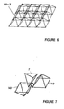
- the third manner is to configure a configuration which consists of polyhedra, the configurations of which have integrity, just as the octahedron O and the tetrahedron T , and polyhedra the configurations of which do not have integrity, just as the cubeoctahedron CO, the semi-octahedron 1 ⁇ 2 O , the semi-cubeoctahedron 1 ⁇ 2 CO ; so that, if we consider the integrity of the configuration which is configured in this manner, the space lattice structure will be characterized by complete vector equilibrium.
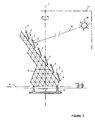
- Figure 1 shows a set of arrays of photovoltaic cells 2 which are fixed on flat structures 3, a space lattice structure 4 to which the flat structures 3 are connected, and a foundation 6 having a bearing plane 5.
- the set of arrays of photovoltaic cells 2 is a subset of the superset of arrays of photovoltaic cells of the photovoltaic power station according to the present invention.
- the space lattice structure of figure 1 rotates, with respect to the above-mentioned foundation 6, about one and only one axis 7, which is perpendicular to the bearing plane 5.
- the rotational movement about axis 7 is carried out in such a way that the space lattice structure 4 follows only the East - West daily movement of the sun 10, so that the rays 12 of the sun 10 are perpendicular to the parallel axes 8.
- the rotational movements of the flat structures 3 about the axes 8 are carried out in such a way that the planes of the arrays of photovoltaic cells 2 are perpendicular to the rays 12 of the sun 10 and, in this way, follow the elevational angle of the sun 10.
- the rotational movement of the space lattice structure 4 about the axis 7 is realized with a specific rotation mechanism and the positioning is achieved through an encoder, using a software for the determination of the East-West position (the azimuthal angle) of the sun, as a function of the geographical latitude and longitude of the photovoltaic power station, the date and the time.
- the rotational movements of the flat structures 3 about axes 8 are realized with rotation mechanisms and the positioning of the elevational angle of the sun is achieved through a second encoder, using a software for the determination of the elevational angle of the sun, as a function of the geographical latitude and longitude of the photovoltaic power station, the date and the time.
- the sectional view of the space lattice structure of figure 1 which is shown in figure 2 , is done by the plane which passes through axis 7 and is perpendicular to the parallel axes 8; and which in figure 2 coincides with plane 11 which is determined by the axis 7 and the center of the sun 10.
- the imaginary ray 12 of the sun 10 which is shown in figure 2 is perpendicular to the plane of any one of the arrays of photovoltaic cells 2.
- the space lattice structure which is shown in figure 2 comprises a space lattice structure which is configured with octahedrons O , tetrahedrons T and semi-octahedrons 1 ⁇ 2 O , as has been illustrated hereinbefore and with reference to figures 4, 5 and 3 , the framework members are thin walled metal tubes and the structure is realized, e.g. according to patent No. GR1004187 , with identical framework members (of the same length, section and ends) and with identical node connectors 1 (of the same size; and of the same orientation and size, of holes).
- the space lattice structure of figures 1 and 2 were configured only with octahedrons O and tetrahedrons T , then it could be expanded in space just in four directions (perpendicular to the four faces of any tetrahedron T ) and could form just four corresponding sets of parallel plane surfaces, perpendicular to these directions, for fixing arrays of photovoltaic cells 2.
- the semi-octahedron 1 ⁇ 2 O we have one more direction and one more plane surface, that to which the flat structures 3, which bear the arrays of photovoltaic cells, are connected.
Landscapes
- Engineering & Computer Science (AREA)
- Physics & Mathematics (AREA)
- Life Sciences & Earth Sciences (AREA)
- Sustainable Development (AREA)
- Sustainable Energy (AREA)
- Thermal Sciences (AREA)
- Chemical & Material Sciences (AREA)
- Combustion & Propulsion (AREA)
- Mechanical Engineering (AREA)
- General Engineering & Computer Science (AREA)
- Photovoltaic Devices (AREA)
Claims (5)
- Eine Solarstation konfiguriert um Sonnenenergie auszunutzen, gennante Solarstation umfassend:- mindestens zwei Solarmodulen (2) und mindestens zwei flachen Strukturen (3);- mindestens einer Raumgitterstruktur (4), die aus Rahmenteilen und Knotenverbindungen (1) besteht, wobei gennanten Rahmenteile an ihren Enden durch gennanten Knotenverbindungen (1) miteinander verbunden sind, in einer Anordnung bestehend aus mindestens einem Semi-Oktaeder (½ O ) und mindestens einem Tetraeder ( T ) deren Flächen in einer einander gegenüber zuordnung sind;- mindestens einem Fundament (6), das eine Tragfläche (5) hat;wobei:- gennanten mindestens zwei Solarvorrichtungen (2) jeweils an den gennanten mindestens zwei flachen Strukturen (3) montiert sind,- gennanten mindestens zwei flachen Strukturen (3) an der gennanten Raumgitterstruktur (4) verbunden sind,- gennante Raumgitterstruktur (4) rotiert in Bezug auf das gennantes mindestens ein Fundament (6) um eine einzige Achse (7), die senkrecht zur gennante Tragfläche (5) steht;dadurch gekennzeichnet, dass:- gennante Solarstation ein Solarkraftwerk ist, wobei gennanten mindestens zwei Solarvorrichtungen (2) mindestens zwei Reihen Solarzellen (2) sind, gennante Solarstation ein Photovoltaikkraftwerk ist, angeordnet, um elektrische Energie durch Solarenergie zu erzeugen; gennanten Rahmenteile mit den Knotenverbindungen (1) gelenkig verbunden sind, gennante Anordnung strukturelle Integrität besitzt, und gennante Raumgitterstruktur (4) durch ein komplettes Vektorengleichgewicht gekennzeichnet wird; und die notwendige Bedingung E=3·V-6 erfüllt ist, wobei die Anzahl der Rahmenteile und Knotenverbindungen (1) mit E bzw. V ausgedrückt wird; und- gennante Solarstation ferner mindestens ein Oktaeder ( O ) umfasst, wobei gennante Raumgitterstruktur (4) gennantes mindestens ein Oktaeder ( O ) umfasst.
- Eine Solarstation nach Anspruch 1, dadurch gekennzeichnet, dass:- gennante Raumgitterstruktur (4) ferner mindestens ein Kuboktaeder (CO) umfasst.
- Eine Solarstation nach jedwedem der vorangehenden Ansprüche,
dadurch gekennzeichnet, dass:- gennante Raumgitterstruktur (4) ferner mindestens ein Semi-Kuboktaeder (½CO) umfasst. - Eine Solarstation nach jedwedem der vorangehenden Ansprüche,
dadurch gekennzeichnet, dass:- gennanten mindestens zwei flachen Strukturen (3) mit der Raumgitterstruktur (4) fest verbunden sind. - Eine Solarstation nach jedwedem der Ansprüche 1 bis 3, dadurch gekennzeichnet, dass:- gennanten mindestens zwei flachen Strukturen (3) drehverstellbar mit der gennanten Raumgitterstruktur (4) verbunden sind und in Bezug auf die Raumgitterstruktur (4) jeweils um die Achsen (8) rotieren; und- genannten Achsen (8) parallel zueinander und parallel zur gennanten Tragfläche (5) sind.
Applications Claiming Priority (1)
| Application Number | Priority Date | Filing Date | Title |
|---|---|---|---|
| GR20060100634A GR20060100634A (el) | 2006-11-21 | 2006-11-21 | Φωτοβολταϊκος σταθμος. |
Publications (4)
| Publication Number | Publication Date |
|---|---|
| EP1925891A2 EP1925891A2 (de) | 2008-05-28 |
| EP1925891A3 EP1925891A3 (de) | 2010-10-06 |
| EP1925891B1 true EP1925891B1 (de) | 2014-07-02 |
| EP1925891B9 EP1925891B9 (de) | 2014-11-19 |
Family
ID=39123587
Family Applications (1)
| Application Number | Title | Priority Date | Filing Date |
|---|---|---|---|
| EP07386027.2A Not-in-force EP1925891B9 (de) | 2006-11-21 | 2007-11-20 | Vorrichtung zur Erzeugung von photovoltaischer Energie |
Country Status (2)
| Country | Link |
|---|---|
| EP (1) | EP1925891B9 (de) |
| GR (1) | GR20060100634A (de) |
Cited By (1)
| Publication number | Priority date | Publication date | Assignee | Title |
|---|---|---|---|---|
| EP3861632B1 (de) * | 2018-10-04 | 2024-03-20 | Achilleas GKAMANIS | Verbessertes solarkraftwerk |
Families Citing this family (8)
| Publication number | Priority date | Publication date | Assignee | Title |
|---|---|---|---|---|
| DE102008013477A1 (de) * | 2008-03-10 | 2009-09-24 | Alfons Stettmeier | Solarmodulträger (Tracker) |
| CN102027298B (zh) * | 2008-03-31 | 2012-11-28 | 皮雷利&C.有限公司 | 太阳跟踪设备 |
| EP2108900A1 (de) * | 2008-04-07 | 2009-10-14 | Costantino Ferdinado Ponziano C.E.M. S.r.l. | Sonnennachführeinrichtung |
| IT1393378B1 (it) * | 2008-09-12 | 2012-04-20 | Venturelli | Apparecchiatura ad inseguimento della irradiazione solare per pannelli di cattura di essa |
| DE102009045033A1 (de) * | 2009-03-12 | 2010-10-07 | Georg-Simon-Ohm Hochschule für angewandte Wissenschaften Fachhochschule Nürnberg | Nachführeinheit für einen Sonnenkollektor |
| CN101673313B (zh) * | 2009-10-15 | 2011-03-02 | 山东电力研究院 | 用于电力系统暂/动态分析的光伏电站数学建模方法 |
| ITBA20120032A1 (it) * | 2012-05-24 | 2013-11-25 | Giuseppe Giacomino | Struttura verticale per pannelli solari |
| CN103938643A (zh) * | 2014-04-28 | 2014-07-23 | 润峰电力有限公司 | 一种光伏电站水坠砂基础施工工艺 |
Family Cites Families (7)
| Publication number | Priority date | Publication date | Assignee | Title |
|---|---|---|---|---|
| US2986241A (en) * | 1956-02-07 | 1961-05-30 | Fuller Richard Buckminster | Synergetic building construction |
| US3974600A (en) * | 1971-08-30 | 1976-08-17 | Synestructics, Inc. | Minimum inventory maximum diversity building system |
| DE7726729U1 (de) * | 1977-08-29 | 1981-03-12 | M.A.N. Maschinenfabrik Augsburg-Nuernberg Ag, 8000 Muenchen | Tragstruktur fuer grossflaechige sonnenkollektor-anlagen |
| DE3500694A1 (de) * | 1985-01-11 | 1986-07-17 | Joachim Dipl.-Ing. 7000 Stuttgart Wenzel | Solarkraftwerk |
| US5448868A (en) * | 1992-10-21 | 1995-09-12 | Lalvani; Haresh | Periodic space structures composed of two nodal polyhedra for design applications |
| US5934271A (en) * | 1994-07-19 | 1999-08-10 | Anutech Pty Limited | Large aperture solar collectors with improved stability |
| DE20217671U1 (de) * | 2002-11-15 | 2003-04-10 | Schulz, Karlheinz, 64832 Babenhausen | Trägeranlage gefertigt aus Stahlrohr für die Aufnahme photovoltaischer Module über Autobahnen und anderen Verkehrswegen |
-
2006
- 2006-11-21 GR GR20060100634A patent/GR20060100634A/el not_active IP Right Cessation
-
2007
- 2007-11-20 EP EP07386027.2A patent/EP1925891B9/de not_active Not-in-force
Cited By (1)
| Publication number | Priority date | Publication date | Assignee | Title |
|---|---|---|---|---|
| EP3861632B1 (de) * | 2018-10-04 | 2024-03-20 | Achilleas GKAMANIS | Verbessertes solarkraftwerk |
Also Published As
| Publication number | Publication date |
|---|---|
| EP1925891A2 (de) | 2008-05-28 |
| GR20060100634A (el) | 2008-06-18 |
| EP1925891A3 (de) | 2010-10-06 |
| EP1925891B9 (de) | 2014-11-19 |
Similar Documents
| Publication | Publication Date | Title |
|---|---|---|
| EP1925891B9 (de) | Vorrichtung zur Erzeugung von photovoltaischer Energie | |
| US9097438B2 (en) | Central receiver solar system comprising a heliostat field | |
| US8188413B2 (en) | Terrestrial concentrator solar tracking photovoltaic array | |
| US8967946B2 (en) | Modular wind-solar energy converting assembly | |
| US20140053825A1 (en) | Ganged single axis solar tracker and its drive system | |
| Gurfude et al. | Energy yield of tracking type floating solar PV plant | |
| GB2383978A (en) | Platform provided with a plurality of renewable energy converter systems | |
| WO2012046134A1 (en) | Tracker apparatus for capturing solar energy and relative axis movement mechanism | |
| WO2013056056A1 (en) | Solar panel assembly with a mounting structure | |
| CN105324935A (zh) | 用于高效率定焦聚光式太阳能热发电厂的装置和方法 | |
| EP0769121A1 (de) | Verbesserte sonnenkollektoren | |
| Xu et al. | Design and optimization of a wave driven solar tracker for floating photovoltaic plants | |
| AU2021346299B2 (en) | Dual-axis solar tracker with hybrid control and possibility of full rotation | |
| CN220964690U (zh) | 一种适用于近海光伏的斜伞状大跨度支架 | |
| CN216721226U (zh) | 一种占地面积小的光伏板阵架设塔 | |
| JP3473831B2 (ja) | モジュール連結型宇宙構造体及びその姿勢制御方法 | |
| WO2005120172A2 (en) | Modular solar concentrating dish | |
| EP4228152A1 (de) | Solarturm | |
| Tryfonos et al. | Generative design and fabrication in the development of an adaptive canopy system with thin-film photovoltaics | |
| Phocas et al. | Comparative load-deformation analysis of an adaptive lightweight canopy system with thin-film photovoltaics | |
| CN222321413U (zh) | 一种海上光伏电站 | |
| Hubach | Solar Tracking Using a Parallel Manipulator Mechanism to Achieve Two-Axis Position Tracking | |
| US20260066834A1 (en) | Synergistic tracking integrated photovoltaic and concentrating cogeneration solar energy harvesting system | |
| JP3184326U (ja) | 太陽光発電装置 | |
| Yellowhair et al. | Optical performance modeling and analysis of a tensile ganged heliostat concept |
Legal Events
| Date | Code | Title | Description |
|---|---|---|---|
| PUAI | Public reference made under article 153(3) epc to a published international application that has entered the european phase |
Free format text: ORIGINAL CODE: 0009012 |
|
| AK | Designated contracting states |
Kind code of ref document: A2 Designated state(s): AT BE BG CH CY CZ DE DK EE ES FI FR GB GR HU IE IS IT LI LT LU LV MC MT NL PL PT RO SE SI SK TR |
|
| AX | Request for extension of the european patent |
Extension state: AL BA HR MK RS |
|
| REG | Reference to a national code |
Ref country code: GR Ref legal event code: PP Ref document number: 20080300014 Country of ref document: GR |
|
| PUAL | Search report despatched |
Free format text: ORIGINAL CODE: 0009013 |
|
| AK | Designated contracting states |
Kind code of ref document: A3 Designated state(s): AT BE BG CH CY CZ DE DK EE ES FI FR GB GR HU IE IS IT LI LT LU LV MC MT NL PL PT RO SE SI SK TR |
|
| AX | Request for extension of the european patent |
Extension state: AL BA HR MK RS |
|
| 17P | Request for examination filed |
Effective date: 20110308 |
|
| AKX | Designation fees paid |
Designated state(s): AT BE BG CH CY CZ DE DK EE ES FI FR GB GR HU IE IS IT LI LT LU LV MC MT NL PL PT RO SE SI SK TR |
|
| GRAP | Despatch of communication of intention to grant a patent |
Free format text: ORIGINAL CODE: EPIDOSNIGR1 |
|
| INTG | Intention to grant announced |
Effective date: 20131018 |
|
| GRAP | Despatch of communication of intention to grant a patent |
Free format text: ORIGINAL CODE: EPIDOSNIGR1 |
|
| INTG | Intention to grant announced |
Effective date: 20140313 |
|
| GRAS | Grant fee paid |
Free format text: ORIGINAL CODE: EPIDOSNIGR3 |
|
| GRAA | (expected) grant |
Free format text: ORIGINAL CODE: 0009210 |
|
| AK | Designated contracting states |
Kind code of ref document: B1 Designated state(s): AT BE BG CH CY CZ DE DK EE ES FI FR GB GR HU IE IS IT LI LT LU LV MC MT NL PL PT RO SE SI SK TR |
|
| REG | Reference to a national code |
Ref country code: GB Ref legal event code: FG4D |
|
| REG | Reference to a national code |
Ref country code: AT Ref legal event code: REF Ref document number: 676139 Country of ref document: AT Kind code of ref document: T Effective date: 20140715 Ref country code: CH Ref legal event code: EP |
|
| REG | Reference to a national code |
Ref country code: IE Ref legal event code: FG4D |
|
| REG | Reference to a national code |
Ref country code: DE Ref legal event code: R096 Ref document number: 602007037445 Country of ref document: DE Effective date: 20140814 |
|
| REG | Reference to a national code |
Ref country code: AT Ref legal event code: MK05 Ref document number: 676139 Country of ref document: AT Kind code of ref document: T Effective date: 20140702 |
|
| REG | Reference to a national code |
Ref country code: NL Ref legal event code: VDEP Effective date: 20140702 |
|
| REG | Reference to a national code |
Ref country code: GR Ref legal event code: EP Ref document number: 20140401982 Country of ref document: GR Effective date: 20141017 |
|
| REG | Reference to a national code |
Ref country code: LT Ref legal event code: MG4D |
|
| PG25 | Lapsed in a contracting state [announced via postgrant information from national office to epo] |
Ref country code: BG Free format text: LAPSE BECAUSE OF FAILURE TO SUBMIT A TRANSLATION OF THE DESCRIPTION OR TO PAY THE FEE WITHIN THE PRESCRIBED TIME-LIMIT Effective date: 20141002 Ref country code: LT Free format text: LAPSE BECAUSE OF FAILURE TO SUBMIT A TRANSLATION OF THE DESCRIPTION OR TO PAY THE FEE WITHIN THE PRESCRIBED TIME-LIMIT Effective date: 20140702 Ref country code: FI Free format text: LAPSE BECAUSE OF FAILURE TO SUBMIT A TRANSLATION OF THE DESCRIPTION OR TO PAY THE FEE WITHIN THE PRESCRIBED TIME-LIMIT Effective date: 20140702 Ref country code: PT Free format text: LAPSE BECAUSE OF FAILURE TO SUBMIT A TRANSLATION OF THE DESCRIPTION OR TO PAY THE FEE WITHIN THE PRESCRIBED TIME-LIMIT Effective date: 20141103 Ref country code: ES Free format text: LAPSE BECAUSE OF FAILURE TO SUBMIT A TRANSLATION OF THE DESCRIPTION OR TO PAY THE FEE WITHIN THE PRESCRIBED TIME-LIMIT Effective date: 20140702 Ref country code: SE Free format text: LAPSE BECAUSE OF FAILURE TO SUBMIT A TRANSLATION OF THE DESCRIPTION OR TO PAY THE FEE WITHIN THE PRESCRIBED TIME-LIMIT Effective date: 20140702 Ref country code: CZ Free format text: LAPSE BECAUSE OF FAILURE TO SUBMIT A TRANSLATION OF THE DESCRIPTION OR TO PAY THE FEE WITHIN THE PRESCRIBED TIME-LIMIT Effective date: 20140702 |
|
| PG25 | Lapsed in a contracting state [announced via postgrant information from national office to epo] |
Ref country code: IS Free format text: LAPSE BECAUSE OF FAILURE TO SUBMIT A TRANSLATION OF THE DESCRIPTION OR TO PAY THE FEE WITHIN THE PRESCRIBED TIME-LIMIT Effective date: 20141102 Ref country code: NL Free format text: LAPSE BECAUSE OF FAILURE TO SUBMIT A TRANSLATION OF THE DESCRIPTION OR TO PAY THE FEE WITHIN THE PRESCRIBED TIME-LIMIT Effective date: 20140702 Ref country code: AT Free format text: LAPSE BECAUSE OF FAILURE TO SUBMIT A TRANSLATION OF THE DESCRIPTION OR TO PAY THE FEE WITHIN THE PRESCRIBED TIME-LIMIT Effective date: 20140702 Ref country code: LV Free format text: LAPSE BECAUSE OF FAILURE TO SUBMIT A TRANSLATION OF THE DESCRIPTION OR TO PAY THE FEE WITHIN THE PRESCRIBED TIME-LIMIT Effective date: 20140702 Ref country code: PL Free format text: LAPSE BECAUSE OF FAILURE TO SUBMIT A TRANSLATION OF THE DESCRIPTION OR TO PAY THE FEE WITHIN THE PRESCRIBED TIME-LIMIT Effective date: 20140702 |
|
| REG | Reference to a national code |
Ref country code: DE Ref legal event code: R097 Ref document number: 602007037445 Country of ref document: DE |
|
| PG25 | Lapsed in a contracting state [announced via postgrant information from national office to epo] |
Ref country code: EE Free format text: LAPSE BECAUSE OF FAILURE TO SUBMIT A TRANSLATION OF THE DESCRIPTION OR TO PAY THE FEE WITHIN THE PRESCRIBED TIME-LIMIT Effective date: 20140702 Ref country code: RO Free format text: LAPSE BECAUSE OF FAILURE TO SUBMIT A TRANSLATION OF THE DESCRIPTION OR TO PAY THE FEE WITHIN THE PRESCRIBED TIME-LIMIT Effective date: 20140702 Ref country code: SK Free format text: LAPSE BECAUSE OF FAILURE TO SUBMIT A TRANSLATION OF THE DESCRIPTION OR TO PAY THE FEE WITHIN THE PRESCRIBED TIME-LIMIT Effective date: 20140702 Ref country code: IT Free format text: LAPSE BECAUSE OF FAILURE TO SUBMIT A TRANSLATION OF THE DESCRIPTION OR TO PAY THE FEE WITHIN THE PRESCRIBED TIME-LIMIT Effective date: 20140702 Ref country code: DK Free format text: LAPSE BECAUSE OF FAILURE TO SUBMIT A TRANSLATION OF THE DESCRIPTION OR TO PAY THE FEE WITHIN THE PRESCRIBED TIME-LIMIT Effective date: 20140702 |
|
| PLBE | No opposition filed within time limit |
Free format text: ORIGINAL CODE: 0009261 |
|
| STAA | Information on the status of an ep patent application or granted ep patent |
Free format text: STATUS: NO OPPOSITION FILED WITHIN TIME LIMIT |
|
| PGFP | Annual fee paid to national office [announced via postgrant information from national office to epo] |
Ref country code: CY Payment date: 20141202 Year of fee payment: 8 |
|
| REG | Reference to a national code |
Ref country code: DE Ref legal event code: R119 Ref document number: 602007037445 Country of ref document: DE |
|
| 26N | No opposition filed |
Effective date: 20150407 |
|
| PG25 | Lapsed in a contracting state [announced via postgrant information from national office to epo] |
Ref country code: LU Free format text: LAPSE BECAUSE OF FAILURE TO SUBMIT A TRANSLATION OF THE DESCRIPTION OR TO PAY THE FEE WITHIN THE PRESCRIBED TIME-LIMIT Effective date: 20141120 Ref country code: MC Free format text: LAPSE BECAUSE OF FAILURE TO SUBMIT A TRANSLATION OF THE DESCRIPTION OR TO PAY THE FEE WITHIN THE PRESCRIBED TIME-LIMIT Effective date: 20140702 Ref country code: BE Free format text: LAPSE BECAUSE OF NON-PAYMENT OF DUE FEES Effective date: 20141130 |
|
| REG | Reference to a national code |
Ref country code: CH Ref legal event code: PL |
|
| GBPC | Gb: european patent ceased through non-payment of renewal fee |
Effective date: 20141120 |
|
| PG25 | Lapsed in a contracting state [announced via postgrant information from national office to epo] |
Ref country code: LI Free format text: LAPSE BECAUSE OF NON-PAYMENT OF DUE FEES Effective date: 20141130 Ref country code: CH Free format text: LAPSE BECAUSE OF NON-PAYMENT OF DUE FEES Effective date: 20141130 |
|
| REG | Reference to a national code |
Ref country code: IE Ref legal event code: MM4A |
|
| REG | Reference to a national code |
Ref country code: FR Ref legal event code: ST Effective date: 20150731 |
|
| PG25 | Lapsed in a contracting state [announced via postgrant information from national office to epo] |
Ref country code: GB Free format text: LAPSE BECAUSE OF NON-PAYMENT OF DUE FEES Effective date: 20141120 Ref country code: DE Free format text: LAPSE BECAUSE OF NON-PAYMENT OF DUE FEES Effective date: 20150602 Ref country code: IE Free format text: LAPSE BECAUSE OF NON-PAYMENT OF DUE FEES Effective date: 20141120 |
|
| PG25 | Lapsed in a contracting state [announced via postgrant information from national office to epo] |
Ref country code: FR Free format text: LAPSE BECAUSE OF NON-PAYMENT OF DUE FEES Effective date: 20141201 Ref country code: SI Free format text: LAPSE BECAUSE OF FAILURE TO SUBMIT A TRANSLATION OF THE DESCRIPTION OR TO PAY THE FEE WITHIN THE PRESCRIBED TIME-LIMIT Effective date: 20140702 |
|
| PG25 | Lapsed in a contracting state [announced via postgrant information from national office to epo] |
Ref country code: CY Free format text: LAPSE BECAUSE OF NON-PAYMENT OF DUE FEES Effective date: 20151120 Ref country code: TR Free format text: LAPSE BECAUSE OF FAILURE TO SUBMIT A TRANSLATION OF THE DESCRIPTION OR TO PAY THE FEE WITHIN THE PRESCRIBED TIME-LIMIT Effective date: 20140702 Ref country code: HU Free format text: LAPSE BECAUSE OF FAILURE TO SUBMIT A TRANSLATION OF THE DESCRIPTION OR TO PAY THE FEE WITHIN THE PRESCRIBED TIME-LIMIT; INVALID AB INITIO Effective date: 20071120 Ref country code: BE Free format text: LAPSE BECAUSE OF FAILURE TO SUBMIT A TRANSLATION OF THE DESCRIPTION OR TO PAY THE FEE WITHIN THE PRESCRIBED TIME-LIMIT Effective date: 20140702 |
|
| PGFP | Annual fee paid to national office [announced via postgrant information from national office to epo] |
Ref country code: MT Payment date: 20141211 Year of fee payment: 8 |
|
| PG25 | Lapsed in a contracting state [announced via postgrant information from national office to epo] |
Ref country code: MT Free format text: LAPSE BECAUSE OF FAILURE TO SUBMIT A TRANSLATION OF THE DESCRIPTION OR TO PAY THE FEE WITHIN THE PRESCRIBED TIME-LIMIT Effective date: 20140702 |
|
| PG25 | Lapsed in a contracting state [announced via postgrant information from national office to epo] |
Ref country code: MT Free format text: LAPSE BECAUSE OF FAILURE TO SUBMIT A TRANSLATION OF THE DESCRIPTION OR TO PAY THE FEE WITHIN THE PRESCRIBED TIME-LIMIT Effective date: 20151120 |
|
| PGFP | Annual fee paid to national office [announced via postgrant information from national office to epo] |
Ref country code: GR Payment date: 20181129 Year of fee payment: 12 |
|
| PG25 | Lapsed in a contracting state [announced via postgrant information from national office to epo] |
Ref country code: GR Free format text: LAPSE BECAUSE OF NON-PAYMENT OF DUE FEES Effective date: 20200609 |