EP1925842A1 - Dämpfungsblech für eine Scheibenbremse - Google Patents
Dämpfungsblech für eine Scheibenbremse Download PDFInfo
- Publication number
- EP1925842A1 EP1925842A1 EP07033559A EP07033559A EP1925842A1 EP 1925842 A1 EP1925842 A1 EP 1925842A1 EP 07033559 A EP07033559 A EP 07033559A EP 07033559 A EP07033559 A EP 07033559A EP 1925842 A1 EP1925842 A1 EP 1925842A1
- Authority
- EP
- European Patent Office
- Prior art keywords
- damping
- damping plate
- layer
- piezoelectric layer
- brake
- Prior art date
- Legal status (The legal status is an assumption and is not a legal conclusion. Google has not performed a legal analysis and makes no representation as to the accuracy of the status listed.)
- Granted
Links
- 238000013016 damping Methods 0.000 title claims abstract description 83
- 238000003825 pressing Methods 0.000 claims description 2
- 229910052751 metal Inorganic materials 0.000 abstract description 3
- 239000002184 metal Substances 0.000 abstract description 3
- 238000010521 absorption reaction Methods 0.000 abstract 1
- 239000010410 layer Substances 0.000 description 61
- 239000012790 adhesive layer Substances 0.000 description 4
- 239000000919 ceramic Substances 0.000 description 3
- 239000004020 conductor Substances 0.000 description 3
- 239000000463 material Substances 0.000 description 3
- 238000006243 chemical reaction Methods 0.000 description 2
- 238000011161 development Methods 0.000 description 2
- 230000018109 developmental process Effects 0.000 description 2
- 230000000694 effects Effects 0.000 description 2
- 238000012544 monitoring process Methods 0.000 description 2
- 239000003973 paint Substances 0.000 description 2
- 239000004033 plastic Substances 0.000 description 2
- 230000002441 reversible effect Effects 0.000 description 2
- 239000005060 rubber Substances 0.000 description 2
- 230000004913 activation Effects 0.000 description 1
- JRPBQTZRNDNNOP-UHFFFAOYSA-N barium titanate Chemical compound [Ba+2].[Ba+2].[O-][Ti]([O-])([O-])[O-] JRPBQTZRNDNNOP-UHFFFAOYSA-N 0.000 description 1
- 229910002113 barium titanate Inorganic materials 0.000 description 1
- 230000008901 benefit Effects 0.000 description 1
- 230000005540 biological transmission Effects 0.000 description 1
- 230000008859 change Effects 0.000 description 1
- 238000000576 coating method Methods 0.000 description 1
- 230000008602 contraction Effects 0.000 description 1
- 238000001514 detection method Methods 0.000 description 1
- 230000010339 dilation Effects 0.000 description 1
- NKZSPGSOXYXWQA-UHFFFAOYSA-N dioxido(oxo)titanium;lead(2+) Chemical compound [Pb+2].[O-][Ti]([O-])=O NKZSPGSOXYXWQA-UHFFFAOYSA-N 0.000 description 1
- 230000010354 integration Effects 0.000 description 1
- 238000004519 manufacturing process Methods 0.000 description 1
- 230000010355 oscillation Effects 0.000 description 1
- 230000009467 reduction Effects 0.000 description 1
Images
Classifications
-
- F—MECHANICAL ENGINEERING; LIGHTING; HEATING; WEAPONS; BLASTING
- F16—ENGINEERING ELEMENTS AND UNITS; GENERAL MEASURES FOR PRODUCING AND MAINTAINING EFFECTIVE FUNCTIONING OF MACHINES OR INSTALLATIONS; THERMAL INSULATION IN GENERAL
- F16D—COUPLINGS FOR TRANSMITTING ROTATION; CLUTCHES; BRAKES
- F16D65/00—Parts or details
- F16D65/0006—Noise or vibration control
- F16D65/0012—Active vibration dampers
-
- F—MECHANICAL ENGINEERING; LIGHTING; HEATING; WEAPONS; BLASTING
- F16—ENGINEERING ELEMENTS AND UNITS; GENERAL MEASURES FOR PRODUCING AND MAINTAINING EFFECTIVE FUNCTIONING OF MACHINES OR INSTALLATIONS; THERMAL INSULATION IN GENERAL
- F16D—COUPLINGS FOR TRANSMITTING ROTATION; CLUTCHES; BRAKES
- F16D65/00—Parts or details
- F16D65/02—Braking members; Mounting thereof
- F16D65/04—Bands, shoes or pads; Pivots or supporting members therefor
- F16D65/092—Bands, shoes or pads; Pivots or supporting members therefor for axially-engaging brakes, e.g. disc brakes
- F16D65/095—Pivots or supporting members therefor
- F16D65/097—Resilient means interposed between pads and supporting members or other brake parts
- F16D65/0971—Resilient means interposed between pads and supporting members or other brake parts transmitting brake actuation force, e.g. elements interposed between brake piston and pad
-
- F—MECHANICAL ENGINEERING; LIGHTING; HEATING; WEAPONS; BLASTING
- F16—ENGINEERING ELEMENTS AND UNITS; GENERAL MEASURES FOR PRODUCING AND MAINTAINING EFFECTIVE FUNCTIONING OF MACHINES OR INSTALLATIONS; THERMAL INSULATION IN GENERAL
- F16D—COUPLINGS FOR TRANSMITTING ROTATION; CLUTCHES; BRAKES
- F16D2121/00—Type of actuator operation force
- F16D2121/18—Electric or magnetic
- F16D2121/28—Electric or magnetic using electrostrictive or magnetostrictive elements, e.g. piezoelectric elements
-
- F—MECHANICAL ENGINEERING; LIGHTING; HEATING; WEAPONS; BLASTING
- F16—ENGINEERING ELEMENTS AND UNITS; GENERAL MEASURES FOR PRODUCING AND MAINTAINING EFFECTIVE FUNCTIONING OF MACHINES OR INSTALLATIONS; THERMAL INSULATION IN GENERAL
- F16D—COUPLINGS FOR TRANSMITTING ROTATION; CLUTCHES; BRAKES
- F16D2129/00—Type of operation source for auxiliary mechanisms
- F16D2129/06—Electric or magnetic
- F16D2129/12—Electrostrictive or magnetostrictive elements, e.g. piezoelectric
Definitions
- the present invention relates to a damping plate for disc brakes for reducing and / or controlling mechanical vibrations of a disc brake system.
- Damping plates of the type mentioned are primarily used in disc brakes of vehicles use. These are to decouple a brake piston vibrationally from a lining carrier plate and prevent metallic contact between these two components.
- the damping plate is therefore usually provided on the underside of a lining carrier plate, at the top of which the brake disc acting on the friction lining is arranged.
- the activation of the actuator takes place on the basis of the oscillation signals determined by the sensor.
- the sensors and actuators designed as piezoelectric elements are arranged between a brake lining on the one hand and a pressure piston on the other hand.
- the present invention is therefore an object of the invention to provide improved vibration damping and vibration control for disc brakes, which can be produced with cost savings, a reduced workload and with a reduction of components and is easier to maintain.
- the intended for a disc brake inventive damping plate is designed for attachment to the back or bottom of a lining carrier plate, at the front or top of which is engageable with the brake disc engageable friction lining.
- the damping plate provided on the underside of the lining carrier plate has at least one piezoelectric layer. Accordingly, the damping plate is formed according to the invention as an active vibration damping element.
- the damping plate can thus the functions previously known Combine damping plates with those actively vibration damping systems in a simple manner and so provide a universally applicable, highly efficient component available, which, depending on the configuration, can be adapted to different requirement profiles.
- the damping element to be designated as a damping plate can alternatively also have completely a piezoelectric layer.
- a damping plate instead of a damping plate, it is therefore also possible to speak of a piezoelectric layer provided on the underside of a lining carrier plate of a brake lining or arranged thereon. This is preferably arranged directly or indirectly on the brake pad associated or facing side of the lining carrier plate, optionally with the interposition of a conventional damping plate made of metal.
- At least one piezoelectric layer according to the invention can be used instead of a damping sheet.
- the introduction or application of the piezoelectric layer in or on the damping plate can be effected by means of common coating methods.
- a separate and complex assembly of piezoelectric elements in a brake device, for example between lining carrier plate and piston, is therefore no longer necessary, since a piezoelectric layer is now provided directly on the brake pad.
- the piezoelectric layer preferably extends homogeneously over the entire surface of the damping plate.
- the piezoelectric layer is designed for detecting mechanical stresses and / or for detecting mechanical vibrations. According to the mechanical stress acting on the piezoelectric layer, this generates an electrical voltage which can be evaluated by a control or control unit, which is electrically conductively connected to the damping plate or to the piezoelectric layer.
- the piezoelectric layer can also be designed as an actuator. This is then connected to a control or control module and can be applied by applying appropriate electrical signals for a length contraction or dilation.
- the piezoelectric layer is designed both as a sensor and as an actuator.
- it can be operated alternately as a sensor and as an actuator in successive time intervals.
- the piezoelectric layer is operable in both an actuator mode and a sensor mode. Switching between the sensor mode and actuator mode via corresponding electrical signals that can be supplied from the control or control module of the piezoelectric layer.
- the damping plate a plurality of superposed and electrically isolated from each other piezoelectric layers are arranged, which can be operated simultaneously in different operating modes. While one of the piezoelectric layers converts mechanical vibrations into electrical signals, the other or further piezoelectric layers may act as mechanical actuators or actuators.
- the piezoelectric layer is formed as a piezoceramic layer.
- Such piezoceramics are in a special way both as a sensor and as an actuator.
- the piezoelectric effect is particularly good reversible in these materials. They are suitable in almost the same way for the conversion of a mechanical force into an electrical signal and vice versa for the conversion of electrical signals into mechanical forces.
- Examples of candidate piezoelectric ceramics include lead zirconate, lead titanate, barium titanate and the like ferroelectric materials.
- the at least one piezoelectric layer is adjacent to at least one damping layer of the damping plate and / or enclosed by a damping layer or embedded in such.
- the damping layer in this case has, for example, the typical three-layer structure. It consists for example of the actual sheet, an adhesive layer for fixing the Sheet on the lining carrier plate and a rubber, plastic or paint layer, which forms a damping layer between the piston and the brake pad.
- the damping plate according to the invention can contribute both actively and passively to the vibration damping or vibration control of a disc brake.
- the damping plate consists essentially completely of a piezoelectric or piezoceramic layer.
- the passive damping properties of the damping plate of the piezoelectric layer or the piezoceramic layer can be at least partially adopted.
- the invention relates to a disc brake device with at least one brake disc and at least one hydraulic actuating device, which is designed for pressing a brake pad against the brake disc.
- the damping plate arranged on a side of a carrier plate facing away from the brake disk has at least one piezoelectric layer in the sense of the invention.
- the damping plate has a multifunctional piezoelectric layer
- the damping plate can be used in a correspondingly versatile manner.
- a damping plate according to the invention or a brake pad having the damping plate can alternatively be provided either on the fist side or on the piston side of the disc brake.
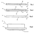
- Figure 1 shows a first embodiment of a damping plate 10 in cross section.
- the damping plate 10 which covers a large part of the underside of the lining carrier plate 18, has two layers 20 and 22. While the layer 22 is formed as a passive vibration damping layer, the layer 20 consists essentially of a piezoelectric material, such as a piezoelectric ceramic.
- This layer 20 is designed as an active vibration damping layer and / or as a sensor.
- two electrical conductors 24 and 26 are provided. These either transmit the electrical signals that can be generated by the layer 20 to the control or monitoring unit.
- these contacts 24, 26 serve to transmit control signals to the piezoelectric layer 20 to be operated as an actuator.
- the passively attenuating layer 22 may further be multi-layered. You can, for example, an adhesive layer for attaching the damping plate to the support plate 18 and for a passive vibration damping as well as a rubber, plastic or paint layer for have mechanical decoupling of the piston or fist and the brake pad.
- the passive damping layer 22 is arranged above the piezoelectric layer 20. This type of arrangement is not mandatory. Thus, reverse arrangements of passive damping layer 22 and active piezoelectric layer 20 are conceivable, as well as any arrangement of an adhesive layer. This can for example also be arranged directly between the piezoelectric layer 20 and the underside of the support plate 18.
- the damping plate 12 has a total of three layers, of which two layers 22 are formed as a passive damping layer and an intermediate layer 20 as an active piezoelectric layer.
- the piezoelectric layer 20 is so to speak enclosed by the damping layer 22 or embedded in this.
- FIG. 3 shows a further exemplary embodiment of a damping plate 14, which is essentially completely formed by a piezoelectric layer 20.
- this damping plate 14 has an adhesive layer, not explicitly shown, with which the Damping plate 14 can be attached to the underside of the lining carrier plate 18.
- a brake pad 16 is shown in cross section.
- a friction lining 17 which can be brought into engagement with the brake disk is arranged, while on the underside of the lining carrier plate 18 the differently shaped damping plates 10, 12, 14 according to FIGS. 1 to 3 can be arranged according to the specific requirements of the brake ,
Landscapes
- Engineering & Computer Science (AREA)
- General Engineering & Computer Science (AREA)
- Mechanical Engineering (AREA)
- Braking Arrangements (AREA)
- Vibration Prevention Devices (AREA)
Abstract
Description
- Die vorliegende Erfindung betrifft ein Dämpfungsblech für Scheibenbremsen zur Reduzierung und/oder zur Kontrolle mechanischer Schwingungen einer Scheibenbremsanlage.
- Bei Scheibenbremsen kann oftmals eine unerwünschte und störende Geräuschentwicklung beobachtet werden, die gerne auch als Bremsenquietschen bezeichnet wird. Der Grund für diese Geräuschentwicklungen wird in einem Auftreten selbst erregter Schwingungen gesehen, die durch von den Reibkräften verursachte Instabilitäten hervorgerufen werden können. Ein solch selbst erregtes Bremssystem schwingt unter Einwirkung von Nichtlinearitäten letztendlich in einem Grenzbereich.
- Gründe für diese Instabilität finden sich zum Beispiel in der Abhängigkeit der Reibeigenschaften von der Geschwindigkeit oder in einer Änderung der Kontaktgeometrie zwischen Bremsscheibe und Bremsbelägen, die zu einer veränderten Reibkraft führt. Weiterhin sind sogenannte Flatter-Instabilitäten bekannt, die auch bei konstantem Reibwert auftreten kann.
- Eine kostengünstig und einfach zu realisierende Möglichkeit zur Verringerung von Schwingungsvorgängen in einer Scheibenbremsvorrichtung besteht in der Verwendung von Dämpfungsblechen.
- Dämpfungsbleche der eingangs genannten Art finden vornehmlich in Scheibenbremsen von Fahrzeugen Verwendung. Diese sollen einen Bremskolben schwingungsmäßig von einer Belagträgerplatte abkoppeln und einen metallischen Kontakt zwischen diesen beiden Bauteilen verhindern. Das Dämpfungsblech ist daher zumeist an der Unterseite einer Belagträgerplatte vorgesehen, an deren Oberseite der auf die Bremsscheibe einwirkende Reibbelag angeordnet ist.
- Aus der
EP 0 748 947 A1 als auch derEP 0 744 558 A1 sind bereits aktive schwingungsdämpfende Systeme für Scheibenbremsen bekannt. Diesen Systemen ist gemein, dass sie auf einer Seite der Bremsscheibe, zum Beispiel der Kolbenseite, einen Schwingungssensor und auf der jeweils gegenüberliegenden Seite der Bremsscheibe, zum Beispiel der Faustseite, einen Aktor oder Aktuator aufweisen. - Die Ansteuerung des Aktuators erfolgt auf der Basis der vom Sensor ermittelten Schwingungssignale. Die als piezoelektrische Elemente ausgebildeten Sensoren und Aktoren sind zwischen einem Bremsbelag einerseits und einem Druckkolben andererseits angeordnet.
- Derartige aktiv vibrationsdämpfende Systeme für Scheibenbremsen sind relativ aufwändig in der Herstellung und in der Wartung. Zudem müssen beiderseits der Bremsscheibe ein Aktor-Sensor-Paar angeordnet und mit entsprechenden Steuerungs- oder Detektionsmodulen elektrisch leitend verbunden werden. So erfordert auch das Auswechseln zerschlissener Bremsbeläge ein Herausnehmen und nachträgliches Wiedereinsetzen der Sensoren und Aktoren, was zu einem erhöhten Arbeitsaufwand führt.
- Der vorliegenden Erfindung liegt daher die Aufgabe zugrunde, eine verbesserte Schwingungsdämpfung und Schwingungskontrolle für Scheibenbremsen zur Verfügung zu stellen, die unter Kosteneinsparung, einem verringerten Arbeitsaufwand sowie unter einer Reduzierung von Bauteilen hergestellt werden kann und leichter zu warten ist.
- Die der Erfindung zugrunde liegende Aufgabe wird mittels eines Dämpfungsblechs gemäß Patentanspruch 1 sowie einer Scheibenbremsvorrichtung gemäß Anspruch 9 gelöst. Weitere vorteilhafte Ausführungsformen der Erfindung sind in den jeweiligen Unteransprüchen angegeben.
- Das für eine Scheibenbremse vorgesehene erfindungsgemäße Dämpfungsblech ist zur Anbringung an der Rückseite bzw. Unterseite einer Belagträgerplatte ausgebildet, an deren Vorderseite bzw. Oberseite sich der mit der Bremsscheibe in Eingriff bringbare Reibbelag befindet.
- Das an der Unterseite der Belagträgerplatte vorgesehene Dämpfungsblech weist zumindest eine piezoelektrische Schicht auf. Demgemäß ist das Dämpfungsblech nach der Erfindung als aktiv schwingungsdämpfendes Element ausgebildet. Das Dämpfungsblech kann somit die Funktionen vorbekannter Dämpfungsbleche mit denen aktiv schwingungsdämpfender Systeme in einfacher Art und Weise kombinieren und so ein universell verwendbares, hocheffizientes Bauteil zur Verfügung stellen, welches, je nach Konfiguration, unterschiedlichen Anforderungsprofilen angepasst werden kann.
- Das als Dämpfungsblech zu bezeichnende Dämpfungselement kann alternativ auch vollständig eine piezoelektrische Schicht aufweisen. Bei einer solchen Ausbildung kann daher anstelle eines Dämpfungsblechs auch von einer an der Unterseite einer Belagträgerplatte eines Bremsbelags vorgesehenen oder daran angeordneten piezoelektrischen Schicht gesprochen werden. Diese ist vorzugsweise unmittelbar oder mittelbar an der einem Bremsstößel zugeordneten oder zugewandten Seite der Belagträgerplatte, gegebenenfalls unter Zwischenschaltung eines herkömmlichen Dämpfungsblechs aus Metall angeordnet.
- Auch kann für sämtliche in der vorliegenden Anmeldung beschriebenen Ausführungen anstelle eines Dämpfungsblechs zumindest eine erfindungsgemäße piezoelektrische Schicht Verwendung finden.
- Das Einbringen oder Aufbringen der piezoelektrischen Schicht in das oder auf das Dämpfungsblech kann mittels gängiger Beschichtungsverfahren erfolgen. Eine separate und aufwändige Montage piezoelektrischer Elemente in einer Bremsvorrichtung, beispielsweise zwischen Belagträgerplatte und Kolben, ist daher nicht mehr nötig, da eine piezoelektrische Schicht nunmehr unmittelbar am Bremsbelag vorgesehen ist.
- Die piezoelektrische Schicht erstreckt sich vorzugsweise homogen über die gesamte Fläche des Dämpfungsblechs.
- Nach einer ersten vorteilhaften Ausführungsform der Erfindung ist die piezoelektrische Schicht zur Erfassung mechanischer Beanspruchungen und/oder zur Erfassung mechanischer Schwingungen ausgebildet. Entsprechend der auf die piezoelektrische Schicht einwirkenden mechanischen Beanspruchung erzeugt diese eine elektrische Spannung, die von einer Kontroll- oder Steuereinheit ausgewertet werden kann, welche elektrisch leitend mit dem Dämpfungsblech bzw. mit der piezoelektrischen Schicht verbunden ist.
- In entsprechender Art und Weise kann die piezoelektrische Schicht auch als Aktor ausgebildet sein. Dieser ist dann an ein Steuer- oder Kontrollmodul angeschlossen und kann unter Beaufschlagung entsprechender elektrischer Signale für eine Längenkontraktion oder -dilatation Verwendung finden.
- Nach einer weiteren bevorzugten Ausführungsform der Erfindung ist die piezoelektrische Schicht sowohl als Sensor als auch als Aktor ausgebildet. Sie kann beispielsweise in aufeinanderfolgenden zeitlichen Intervallen wechselweise als Sensor und als Aktor betrieben werden. So ist die piezoelektrische Schicht sowohl in einem Aktormodus als auch in einem Sensormodus betreibbar. Ein Umschalten zwischen Sensormodus und Aktormodus erfolgt über entsprechende elektrische Signale, die vom Steuer- oder Kontrollmodul der piezoelektrischen Schicht zugeführt werden können.
- Weiterhin ist denkbar, dass im Dämpfungsblech mehrere übereinanderliegende und elektrisch voneinander isolierte piezoelektrische Schichten angeordnet sind, die gleichzeitig in unterschiedlichen Betriebsmodi betrieben werden können. Während eine der piezoelektrischen Schichten mechanische Schwingungen in elektrische Signale umwandelt, kann die andere oder können weitere piezoelektrische Schichten als mechanische Aktoren oder Aktuatoren fungieren.
- Nach einer weiteren vorteilhaften Ausführungsform ist vorgesehen, dass die piezoelektrische Schicht als piezokeramische Schicht ausgebildet ist. Solche Piezokeramiken eignen sich in besonderer Art und Weise sowohl als Sensor als auch als Aktuator. Der piezoelektrische Effekt ist in diesen Materialien besonders gut umkehrbar. Sie eignen sich in nahezu gleicher Weise zur Umwandlung einer mechanischen Kraft in ein elektrisches Signal als auch umgekehrt für die Umwandlung elektrischer Signale in mechanische Kräfte. Beispiele für infrage kommende piezoelektrische Keramiken sind beispielsweise Bleizirkonat, Bleititanat, Bariumtitanat und dergleichen ferroelektrische Materialien.
- Weiterhin ist vorgesehen, dass die zumindest eine piezoelektrische Schicht an zumindest eine Dämpfungsschicht des Dämpfungsblechs angrenzt und/oder von einer Dämpfungsschicht umschlossen oder in eine solche eingebettet ist.
- Die Dämpfungsschicht weist hierbei zum Beispiel den typischen dreischichtigen Aufbau auf. Sie besteht beispielsweise aus dem eigentlichen Blech, einer Klebschicht zur Befestigung des Blechs auf der Belagträgerplatte und einer Gummi-, Kunststoff- oder Lackschicht, die eine Dämpfungsschicht zwischen dem Kolben und dem Bremsbelag bildet. Auf diese Art und Weise kann das erfindungsgemäße Dämpfungsblech sowohl aktiv als auch passiv zur Schwingungsdämpfung oder Schwingungskontrolle einer Scheibenbremse beitragen.
- Alternativ hierzu kann vorgesehen sein, dass das Dämpfungsblech im Wesentlichen vollständig aus einer piezoelektrischen oder piezokeramischen Schicht besteht. Bei dieser Ausführungsform können sogar die passiven Dämpfungseigenschaften des Dämpfungsblechs von der piezoelektrischen Schicht oder der piezokeramischen Schicht zumindest ansatzweise übernommen werden.
- Die Integration einer piezoelektrischen Schicht in das Dämpfungsblech bzw. die Realisierung des Dämpfungsbleches als piezokeramische Schicht hat den Vorteil, dass auch herkömmliche Scheibenbremsen durch bloßes Austauschen von Bremsbelägen mit erfindungsgemäßen Dämpfungsblech in besonders einfacher und kosteneinsparender Weise nachgerüstet werden können.
- Nach einem weiteren unabhängigen Aspekt betrifft die Erfindung einer Scheibenbremsvorrichtung mit zumindest einer Bremsscheibe und zumindest einer hydraulischen Betätigungseinrichtung, welche zum Andrücken eines Bremsbelags an die Bremsscheibe ausgebildet ist. Hierbei weist das an einer der Bremsscheibe abgewandten Seite einer Trägerplatte angeordnete Dämpfungsblech zumindest eine piezoelektrische Schicht im Sinne der Erfindung auf.
- Dadurch, dass das Dämpfungsblech eine multifunktionale piezoelektrische Schicht aufweist, kann das Dämpfungsblech in einer entsprechend vielseitigen Art und Weise verwendet werden. So kann ein erfindungsgemäßes Dämpfungsblech bzw. ein das Dämpfungsblech aufweisender Bremsbelag alternativ entweder an der Faustseite oder an der Kolbenseite der Scheibenbremse vorgesehen werden.
- Natürlich ist es auch möglich, auf beiden Seiten der Scheibenbremse, nämlich, sowohl an der Faustseite als auch an der Kolbenseite einen entsprechenden Bremsbelag mit dem erfindungsgemäßen Dämpfungsblech anzuordnen.
- Weitere Ziele, Merkmale, Eigenschaften sowie vorteilhafte Anwendungsmöglichkeiten der vorliegenden Erfindung ergeben sich aus der nachfolgenden Beschreibung von Ausführungsbeispielen anhand der Zeichnungen. Dabei bilden sämtliche beschriebenen und/oder bildlich dargestellten Merkmale in ihrer sinnvollen Kombination den Gegenstand der vorliegenden Erfindung, auch unabhängig von den Patentansprüchen oder deren Rückbeziehung. Es zeigen:
- Figur 1
- einen schematischen Querschnitt durch ein Dämpfungsblech nach einer ersten Ausführung,
- Figur 2
- einen schematischen Querschnitt durch ein Dämpfungsblech gemäß einer zweiten Ausführung,
- Figur 3
- einen schematischen Querschnitt durch ein als piezoelektrische Keramik ausgebildetes Dämpfungsblech und
- Figur 4
- eine schematische Querschnittsdarstellung eines Bremsbelags.
- Figur 1 zeigt eine erste Ausführungsform eines Dämpfungsblechs 10 im Querschnitt. Das Dämpfungsblech 10, welches einen Großteil der Unterseite der Belagträgerplatte 18 abdeckt, weist zwei Schichten 20 und 22 auf. Während die Schicht 22 als passiv schwingungsdämpfende Schicht ausgebildet ist, besteht die Schicht 20 im Wesentlichen aus einem piezoelektrischen Material, wie etwa einer piezoelektrischen Keramik.
- Diese Schicht 20 ist als aktiv schwingungsdämpfende Schicht und/oder als Sensor ausgebildet. Zur Übermittlung elektrischer Signale zwischen der piezoelektrischen Schicht 20 und einer (nicht explizit dargestellten) Steuer- oder Kontrolleinheit sind zwei elektrische Leiter 24 und 26 vorgesehen. Diese übermitteln entweder die von der Schicht 20 generierbaren elektrischen Signale an die Steuer- oder Kontrolleinheit. Gleichermaßen dienen diese Kontakte 24, 26 der Übermittlung von Steuersignalen an die als Aktor zu betreibende piezoelektrische Schicht 20.
- Die passiv dämpfende Schicht 22 kann des Weiteren mehrschichtig aufgebaut sein. Sie kann beispielsweise eine Klebschicht zur Befestigung des Dämpfungsblechs an der Trägerplatte 18 und für eine passive Schwingungsdämpfung ebenso eine Gummi-, Kunststoff- oder Lackschicht zur mechanischen Entkopplung von Kolben oder Faust und dem Bremsbelag aufweisen.
- In Figur 1 ist die passiv dämpfende Schicht 22 oberhalb der piezoelektrischen Schicht 20 angeordnet. Diese Art der Anordnung ist nicht zwingend. So sind umgekehrte Anordnungen von passiver Dämpfungsschicht 22 und aktiver piezoelektrischer Schicht 20 denkbar, wie auch eine beliebige Anordnung einer Klebschicht. Diese kann beispielsweise auch unmittelbar zwischen piezoelektrischer Schicht 20 und der Unterseite der Trägerplatte 18 angeordnet sein.
- Bei der Ausführungsform nach Figur 2 weist das Dämpfungsblech 12 insgesamt drei Schichten auf, von denen zwei Schichten 22 als passive Dämpfungsschicht und eine dazwischenliegende Schicht 20 als aktive piezoelektrische Schicht ausgebildet sind. Bei dieser Ausführungsform ist die piezoelektrische Schicht 20 sozusagen von der Dämpfungsschicht 22 umschlossen oder in diese eingebettet.
- Weitere Ausführungsformen mit einer Vielzahl übereineinanderliegender piezoelektrischer Schichten 20, die jeweils durch eine passive Dämpfungsschicht 22 voneinander getrennt, zumindest aber elektrisch voneinander isoliert sind, können ebenfalls vorgesehen werden.
- Figur 3 zeigt schließlich ein weiteres Ausführungsbeispiel eines Dämpfungsblechs 14, welches im Wesentlichen vollständig von einer piezoelektrischen Schicht 20 gebildet wird. Selbstredend weist auch dieses Dämpfungsblech 14 eine nicht explizit dargestellte Klebeschicht auf, mit welcher das Dämpfungsblech 14 an der Unterseite der Belagträgerplatte 18 befestigt werden kann.
- In Figur 4 ist schließlich ein Bremsbelag 16 im Querschnitt dargestellt. An der Oberseite der Belagträgerplatte 18 ist ein mit der Bremsscheibe in Eingriff bringbarer Reibbelag 17 angeordnet, während an der Unterseite der Belagträgerplatte 18 die unterschiedlich ausgebildeten Dämpfungsbleche 10, 12, 14 gemäß der Figuren 1 bis 3 je nach den spezifischen Anforderungen der Bremse angeordnet werden können.
-
- 10
- Dämpfungsblech
- 12
- Dämpfungsblech
- 14
- Dämpfungsblech
- 16
- Bremsbelag
- 17
- Reibbelag
- 18
- Trägerplatte
- 20
- Piezoelektrische Schicht
- 22
- Dämpfungsschicht
- 24
- Elektrischer Leiter
- 26
- Elektrischer Leiter
Claims (10)
- Dämpfungsblech für eine Scheibenbremse, welches zur Anbringung an der Unterseite einer Belagträgerplatte vorgesehen ist, die an ihrer Oberseite mit einem Reibbelag verbunden ist, dadurch gekennzeichnet, dass das Dämpfungsblech (10; 12; 14) zumindest eine piezoelektrische Schicht (20) aufweist.
- Dämpfungsblech nach Anspruch 1, dadurch gekennzeichnet, dass die piezoelektrische Schicht (20) zur Erfassung mechanischer Beanspruchungen und/oder Schwingungen ausgebildet ist.
- Dämpfungsblech nach einem der vorhergehenden Ansprüche, dadurch gekennzeichnet, dass die piezoelektrische Schicht (20) als Aktor ausgebildet ist.
- Dämpfungsblech nach einem der vorhergehenden Ansprüche, dadurch gekennzeichnet, dass die piezoelektrische Schicht (20) sowohl als Sensor als auch als Aktor ausgebildet ist.
- Dämpfungsblech nach einem der vorhergehenden Ansprüche, dadurch gekennzeichnet, dass die piezoelektrische Schicht (20) in einem Aktormodus und in einem Sensormodus betreibbar ist.
- Dämpfungsblech nach einem der vorhergehenden Ansprüche, dadurch gekennzeichnet, dass die piezoelektrische Schicht (20) als piezokeramische Schicht ausgebildet ist.
- Dämpfungsblech nach einem der vorhergehenden Ansprüche, dadurch gekennzeichnet, dass die piezoelektrische Schicht (20) an zumindest eine Dämpfungsschicht (22) des Blechs (10; 12) angrenzt und/oder von einer Dämpfungsschicht (22) umschlossen ist.
- Dämpfungsblech nach einem der vorhergehenden Ansprüche 1 bis 6, dadurch gekennzeichnet, dass das Dämpfungsblech (14) im Wesentlichen vollständig aus einer piezokeramischen Schicht (20) besteht.
- Scheibenbremsvorrichtung mit zumindest einer Bremsscheibe, zumindest einer hydraulischen Betätigungseinrichtung zum Andrücken eines an einer Trägerplatte (18) angeordneten Bremsbelags (17) an die Bremsscheibe, einem an der Trägerplatte (18) an ihrer der Bremsscheibe abgewandten Seite vorgesehenen Dämpfungsblech (10; 12; 14) nach einem der vorhergehenden Ansprüche.
- Scheibenbremsvorrichtung nach Anspruch 9, mit mindestens einem an der Faustseite und/oder an der Kolbenseite der Scheibenbremse vorgesehenen Dämpfungsblech (10; 12; 14) nach einem der vorhergehenden Ansprüche 1 bis 8.
Applications Claiming Priority (1)
| Application Number | Priority Date | Filing Date | Title |
|---|---|---|---|
| DE102006054751A DE102006054751A1 (de) | 2006-11-21 | 2006-11-21 | Dämpfungsblech für eine Scheibenbremse |
Publications (2)
| Publication Number | Publication Date |
|---|---|
| EP1925842A1 true EP1925842A1 (de) | 2008-05-28 |
| EP1925842B1 EP1925842B1 (de) | 2009-11-04 |
Family
ID=38869209
Family Applications (1)
| Application Number | Title | Priority Date | Filing Date |
|---|---|---|---|
| EP07033559A Not-in-force EP1925842B1 (de) | 2006-11-21 | 2007-11-17 | Dämpfungsblech für eine Scheibenbremse |
Country Status (4)
| Country | Link |
|---|---|
| EP (1) | EP1925842B1 (de) |
| AT (1) | ATE447679T1 (de) |
| DE (2) | DE102006054751A1 (de) |
| ES (1) | ES2334463T3 (de) |
Families Citing this family (1)
| Publication number | Priority date | Publication date | Assignee | Title |
|---|---|---|---|---|
| DE102014109699A1 (de) * | 2014-07-10 | 2016-01-14 | Federal-Mogul Bremsbelag Gmbh | Bremsbelag mit Vorrichtung zur Reduzierung von Geräuschen |
Citations (4)
| Publication number | Priority date | Publication date | Assignee | Title |
|---|---|---|---|---|
| US5499705A (en) * | 1991-03-12 | 1996-03-19 | Ide; Russell D. | Beam mounted friction pads for use in friction brakes and clutches |
| EP0748947A1 (de) * | 1995-06-13 | 1996-12-18 | Sumitomo Electric Industries, Inc. | Schwingungsdämpfer zur Verwendung in einer Scheibenbremse |
| WO1999023393A1 (en) * | 1997-11-03 | 1999-05-14 | Dana Corporation | Disc brake noise control |
| DE10230008A1 (de) * | 2002-07-04 | 2004-01-15 | Robert Bosch Gmbh | Reibungsbremse |
Family Cites Families (7)
| Publication number | Priority date | Publication date | Assignee | Title |
|---|---|---|---|---|
| US5315203A (en) * | 1992-04-07 | 1994-05-24 | Mcdonnell Douglas Corporation | Apparatus for passive damping of a structure |
| JP3518054B2 (ja) * | 1995-05-26 | 2004-04-12 | 住友電気工業株式会社 | ディスクブレーキ用制振装置 |
| US6213564B1 (en) * | 1997-04-15 | 2001-04-10 | Face International Corp | Anti-lock brake system with piezoelectric brake actuator |
| DE19855467A1 (de) * | 1998-12-01 | 2000-06-08 | Lucas Ind Plc | Vorrichtung mit schwingungsgedämpftem Bauteil, insbesondere eine Bremse |
| DE19909849A1 (de) * | 1999-03-08 | 2000-09-28 | Cww Gerko Akustik Gmbh & Co Kg | Dämpfungsblech |
| DE19931081A1 (de) * | 1999-07-06 | 2001-01-11 | Bosch Gmbh Robert | Verfahren zur Variation der Bremskraft einer Fahrzeugbremse und Fahrzeugbremse |
| FR2834321B1 (fr) * | 2001-12-31 | 2004-02-27 | Bosch Gmbh Robert | Dispositif de freinage, en particulier pour vehicule automobile |
-
2006
- 2006-11-21 DE DE102006054751A patent/DE102006054751A1/de not_active Withdrawn
-
2007
- 2007-11-17 AT AT07033559T patent/ATE447679T1/de not_active IP Right Cessation
- 2007-11-17 DE DE502007001891T patent/DE502007001891D1/de active Active
- 2007-11-17 EP EP07033559A patent/EP1925842B1/de not_active Not-in-force
- 2007-11-17 ES ES07033559T patent/ES2334463T3/es active Active
Patent Citations (4)
| Publication number | Priority date | Publication date | Assignee | Title |
|---|---|---|---|---|
| US5499705A (en) * | 1991-03-12 | 1996-03-19 | Ide; Russell D. | Beam mounted friction pads for use in friction brakes and clutches |
| EP0748947A1 (de) * | 1995-06-13 | 1996-12-18 | Sumitomo Electric Industries, Inc. | Schwingungsdämpfer zur Verwendung in einer Scheibenbremse |
| WO1999023393A1 (en) * | 1997-11-03 | 1999-05-14 | Dana Corporation | Disc brake noise control |
| DE10230008A1 (de) * | 2002-07-04 | 2004-01-15 | Robert Bosch Gmbh | Reibungsbremse |
Also Published As
| Publication number | Publication date |
|---|---|
| ES2334463T3 (es) | 2010-03-10 |
| DE502007001891D1 (de) | 2009-12-17 |
| EP1925842B1 (de) | 2009-11-04 |
| ATE447679T1 (de) | 2009-11-15 |
| DE102006054751A1 (de) | 2008-06-05 |
Similar Documents
| Publication | Publication Date | Title |
|---|---|---|
| DE69605483T2 (de) | Scheibenbremse mit Schwingungsdämpfer | |
| DE69808767T2 (de) | Bremssattel mit verschleissnachstellung | |
| EP2063533B1 (de) | Bedienvorrichtung mit wenigstens einem Druckschalter | |
| DE102008015873A1 (de) | Fahrzeug, insbesondere Schienenfahrzeug, mit einer Einrichtung zur Überwachung der Bremswirkung | |
| EP2197115B1 (de) | Bedienvorrichtung mit wenigstens einem Druckschalter | |
| EP2915256B1 (de) | Eingabeeinrichtung und verfahren zum generieren eines steuersignals | |
| DE202007018898U1 (de) | Piezokeramischer Flächenaktuator | |
| EP3308049A1 (de) | Flexible lagerung von reibbelagelementen in bremsbelägen | |
| DE102015015417A1 (de) | Bedienvorrichtung für einen Kraftwagen und Verfahren zur Erzeugung eines haptischen Signals | |
| EP3698065B1 (de) | Bremsvorrichtung, insbesondere nutzfahrzeugscheibenbremse | |
| DE102011005360A1 (de) | Antriebseinrichtung mit aktiv gelagerter Antriebswelle | |
| EP1925842B1 (de) | Dämpfungsblech für eine Scheibenbremse | |
| DE10336368A1 (de) | Bremsbaugruppe und Verfahren zum Abbremsen eines Fahrzeugs oder einer anderen selektiv bewegbaren Baugruppe | |
| EP1792527B1 (de) | Vorrichtung und verfahren zur schwingungsbeeinflussung eines flächenelementes | |
| DE102007039614A1 (de) | Elektrische Bremse mit geräuschvermindernden Maßnahmen | |
| WO2018192610A1 (de) | Reibkupplungseinrichtung, hybridmodul und antriebsstrang für ein kraftfahrzeug | |
| EP2962008B1 (de) | Elektromagnetisch betätigbare federdruckbremse | |
| DE19602888C1 (de) | Bremsbacke, insbesondere für Nutzfahrzeug-Scheibenbremsen | |
| EP3676140B1 (de) | Bremsaktuator für ein schienenfahrzeug | |
| DE102023119665B3 (de) | Bremssystem und radanordnung für ein fahrzeug sowie verfahren zum betreiben eines bremssystems eines fahrzeugs | |
| DE10143226A1 (de) | Adaptronisches Kombimodul | |
| DE102019001617A1 (de) | Zierteil zur Ausgabe einer haptischen Rückmeldung, insbesondere für ein Kraftfahrzeug | |
| DE102015114112A1 (de) | Bremsvorrichtung eines Kraftfahrzeugs | |
| WO2001002744A1 (de) | Verfahren zur variation der bremskraft einer fahrzeugbremse und fahrzeugbremse | |
| EP3345229B1 (de) | Anordnung und verfahren zur beeinflussung und/oder detektion einer dynamischen oder statischen eigenschaft einer tragstruktur |
Legal Events
| Date | Code | Title | Description |
|---|---|---|---|
| PUAI | Public reference made under article 153(3) epc to a published international application that has entered the european phase |
Free format text: ORIGINAL CODE: 0009012 |
|
| AK | Designated contracting states |
Kind code of ref document: A1 Designated state(s): AT BE BG CH CY CZ DE DK EE ES FI FR GB GR HU IE IS IT LI LT LU LV MC MT NL PL PT RO SE SI SK TR |
|
| AX | Request for extension of the european patent |
Extension state: AL BA HR MK RS |
|
| 17P | Request for examination filed |
Effective date: 20081031 |
|
| AKX | Designation fees paid |
Designated state(s): AT BE BG CH CY CZ DE DK EE ES FI FR GB GR HU IE IS IT LI LT LU LV MC MT NL PL PT RO SE SI SK TR |
|
| 17Q | First examination report despatched |
Effective date: 20090220 |
|
| GRAP | Despatch of communication of intention to grant a patent |
Free format text: ORIGINAL CODE: EPIDOSNIGR1 |
|
| GRAS | Grant fee paid |
Free format text: ORIGINAL CODE: EPIDOSNIGR3 |
|
| GRAA | (expected) grant |
Free format text: ORIGINAL CODE: 0009210 |
|
| AK | Designated contracting states |
Kind code of ref document: B1 Designated state(s): AT BE BG CH CY CZ DE DK EE ES FI FR GB GR HU IE IS IT LI LT LU LV MC MT NL PL PT RO SE SI SK TR |
|
| REG | Reference to a national code |
Ref country code: GB Ref legal event code: FG4D Free format text: NOT ENGLISH |
|
| REG | Reference to a national code |
Ref country code: CH Ref legal event code: EP |
|
| REG | Reference to a national code |
Ref country code: IE Ref legal event code: FG4D |
|
| REF | Corresponds to: |
Ref document number: 502007001891 Country of ref document: DE Date of ref document: 20091217 Kind code of ref document: P |
|
| REG | Reference to a national code |
Ref country code: ES Ref legal event code: FG2A Ref document number: 2334463 Country of ref document: ES Kind code of ref document: T3 |
|
| NLV1 | Nl: lapsed or annulled due to failure to fulfill the requirements of art. 29p and 29m of the patents act | ||
| LTIE | Lt: invalidation of european patent or patent extension |
Effective date: 20091104 |
|
| PG25 | Lapsed in a contracting state [announced via postgrant information from national office to epo] |
Ref country code: SE Free format text: LAPSE BECAUSE OF FAILURE TO SUBMIT A TRANSLATION OF THE DESCRIPTION OR TO PAY THE FEE WITHIN THE PRESCRIBED TIME-LIMIT Effective date: 20091104 Ref country code: LT Free format text: LAPSE BECAUSE OF FAILURE TO SUBMIT A TRANSLATION OF THE DESCRIPTION OR TO PAY THE FEE WITHIN THE PRESCRIBED TIME-LIMIT Effective date: 20091104 Ref country code: PT Free format text: LAPSE BECAUSE OF FAILURE TO SUBMIT A TRANSLATION OF THE DESCRIPTION OR TO PAY THE FEE WITHIN THE PRESCRIBED TIME-LIMIT Effective date: 20100304 Ref country code: IS Free format text: LAPSE BECAUSE OF FAILURE TO SUBMIT A TRANSLATION OF THE DESCRIPTION OR TO PAY THE FEE WITHIN THE PRESCRIBED TIME-LIMIT Effective date: 20100304 Ref country code: FI Free format text: LAPSE BECAUSE OF FAILURE TO SUBMIT A TRANSLATION OF THE DESCRIPTION OR TO PAY THE FEE WITHIN THE PRESCRIBED TIME-LIMIT Effective date: 20091104 |
|
| REG | Reference to a national code |
Ref country code: IE Ref legal event code: FD4D |
|
| BERE | Be: lapsed |
Owner name: TMD FRICTION SERVICES G.M.B.H. Effective date: 20091130 |
|
| PG25 | Lapsed in a contracting state [announced via postgrant information from national office to epo] |
Ref country code: PL Free format text: LAPSE BECAUSE OF FAILURE TO SUBMIT A TRANSLATION OF THE DESCRIPTION OR TO PAY THE FEE WITHIN THE PRESCRIBED TIME-LIMIT Effective date: 20091104 Ref country code: CY Free format text: LAPSE BECAUSE OF FAILURE TO SUBMIT A TRANSLATION OF THE DESCRIPTION OR TO PAY THE FEE WITHIN THE PRESCRIBED TIME-LIMIT Effective date: 20091104 Ref country code: SI Free format text: LAPSE BECAUSE OF FAILURE TO SUBMIT A TRANSLATION OF THE DESCRIPTION OR TO PAY THE FEE WITHIN THE PRESCRIBED TIME-LIMIT Effective date: 20091104 Ref country code: LV Free format text: LAPSE BECAUSE OF FAILURE TO SUBMIT A TRANSLATION OF THE DESCRIPTION OR TO PAY THE FEE WITHIN THE PRESCRIBED TIME-LIMIT Effective date: 20091104 |
|
| PG25 | Lapsed in a contracting state [announced via postgrant information from national office to epo] |
Ref country code: MC Free format text: LAPSE BECAUSE OF NON-PAYMENT OF DUE FEES Effective date: 20091130 |
|
| PG25 | Lapsed in a contracting state [announced via postgrant information from national office to epo] |
Ref country code: BG Free format text: LAPSE BECAUSE OF FAILURE TO SUBMIT A TRANSLATION OF THE DESCRIPTION OR TO PAY THE FEE WITHIN THE PRESCRIBED TIME-LIMIT Effective date: 20100204 Ref country code: IE Free format text: LAPSE BECAUSE OF FAILURE TO SUBMIT A TRANSLATION OF THE DESCRIPTION OR TO PAY THE FEE WITHIN THE PRESCRIBED TIME-LIMIT Effective date: 20091104 Ref country code: EE Free format text: LAPSE BECAUSE OF FAILURE TO SUBMIT A TRANSLATION OF THE DESCRIPTION OR TO PAY THE FEE WITHIN THE PRESCRIBED TIME-LIMIT Effective date: 20091104 Ref country code: DK Free format text: LAPSE BECAUSE OF FAILURE TO SUBMIT A TRANSLATION OF THE DESCRIPTION OR TO PAY THE FEE WITHIN THE PRESCRIBED TIME-LIMIT Effective date: 20091104 Ref country code: RO Free format text: LAPSE BECAUSE OF FAILURE TO SUBMIT A TRANSLATION OF THE DESCRIPTION OR TO PAY THE FEE WITHIN THE PRESCRIBED TIME-LIMIT Effective date: 20091104 |
|
| PG25 | Lapsed in a contracting state [announced via postgrant information from national office to epo] |
Ref country code: SK Free format text: LAPSE BECAUSE OF FAILURE TO SUBMIT A TRANSLATION OF THE DESCRIPTION OR TO PAY THE FEE WITHIN THE PRESCRIBED TIME-LIMIT Effective date: 20091104 Ref country code: CZ Free format text: LAPSE BECAUSE OF FAILURE TO SUBMIT A TRANSLATION OF THE DESCRIPTION OR TO PAY THE FEE WITHIN THE PRESCRIBED TIME-LIMIT Effective date: 20091104 |
|
| PLBE | No opposition filed within time limit |
Free format text: ORIGINAL CODE: 0009261 |
|
| STAA | Information on the status of an ep patent application or granted ep patent |
Free format text: STATUS: NO OPPOSITION FILED WITHIN TIME LIMIT |
|
| 26N | No opposition filed |
Effective date: 20100805 |
|
| PG25 | Lapsed in a contracting state [announced via postgrant information from national office to epo] |
Ref country code: BE Free format text: LAPSE BECAUSE OF NON-PAYMENT OF DUE FEES Effective date: 20091130 Ref country code: GR Free format text: LAPSE BECAUSE OF FAILURE TO SUBMIT A TRANSLATION OF THE DESCRIPTION OR TO PAY THE FEE WITHIN THE PRESCRIBED TIME-LIMIT Effective date: 20100205 |
|
| PG25 | Lapsed in a contracting state [announced via postgrant information from national office to epo] |
Ref country code: AT Free format text: LAPSE BECAUSE OF NON-PAYMENT OF DUE FEES Effective date: 20091117 |
|
| PG25 | Lapsed in a contracting state [announced via postgrant information from national office to epo] |
Ref country code: MT Free format text: LAPSE BECAUSE OF FAILURE TO SUBMIT A TRANSLATION OF THE DESCRIPTION OR TO PAY THE FEE WITHIN THE PRESCRIBED TIME-LIMIT Effective date: 20091104 Ref country code: LU Free format text: LAPSE BECAUSE OF NON-PAYMENT OF DUE FEES Effective date: 20091117 |
|
| PG25 | Lapsed in a contracting state [announced via postgrant information from national office to epo] |
Ref country code: HU Free format text: LAPSE BECAUSE OF FAILURE TO SUBMIT A TRANSLATION OF THE DESCRIPTION OR TO PAY THE FEE WITHIN THE PRESCRIBED TIME-LIMIT Effective date: 20100505 |
|
| PG25 | Lapsed in a contracting state [announced via postgrant information from national office to epo] |
Ref country code: TR Free format text: LAPSE BECAUSE OF FAILURE TO SUBMIT A TRANSLATION OF THE DESCRIPTION OR TO PAY THE FEE WITHIN THE PRESCRIBED TIME-LIMIT Effective date: 20091104 |
|
| PG25 | Lapsed in a contracting state [announced via postgrant information from national office to epo] |
Ref country code: IT Free format text: LAPSE BECAUSE OF NON-PAYMENT OF DUE FEES Effective date: 20101117 |
|
| REG | Reference to a national code |
Ref country code: CH Ref legal event code: PL |
|
| PG25 | Lapsed in a contracting state [announced via postgrant information from national office to epo] |
Ref country code: CH Free format text: LAPSE BECAUSE OF NON-PAYMENT OF DUE FEES Effective date: 20111130 Ref country code: LI Free format text: LAPSE BECAUSE OF NON-PAYMENT OF DUE FEES Effective date: 20111130 |
|
| PG25 | Lapsed in a contracting state [announced via postgrant information from national office to epo] |
Ref country code: NL Free format text: LAPSE BECAUSE OF FAILURE TO SUBMIT A TRANSLATION OF THE DESCRIPTION OR TO PAY THE FEE WITHIN THE PRESCRIBED TIME-LIMIT Effective date: 20091104 |
|
| REG | Reference to a national code |
Ref country code: FR Ref legal event code: PLFP Year of fee payment: 9 |
|
| REG | Reference to a national code |
Ref country code: FR Ref legal event code: PLFP Year of fee payment: 10 |
|
| PGFP | Annual fee paid to national office [announced via postgrant information from national office to epo] |
Ref country code: DE Payment date: 20161130 Year of fee payment: 10 Ref country code: FR Payment date: 20161118 Year of fee payment: 10 Ref country code: GB Payment date: 20161122 Year of fee payment: 10 |
|
| PGFP | Annual fee paid to national office [announced via postgrant information from national office to epo] |
Ref country code: ES Payment date: 20161110 Year of fee payment: 10 Ref country code: IT Payment date: 20161123 Year of fee payment: 10 |
|
| REG | Reference to a national code |
Ref country code: DE Ref legal event code: R119 Ref document number: 502007001891 Country of ref document: DE |
|
| GBPC | Gb: european patent ceased through non-payment of renewal fee |
Effective date: 20171117 |
|
| REG | Reference to a national code |
Ref country code: FR Ref legal event code: ST Effective date: 20180731 |
|
| PG25 | Lapsed in a contracting state [announced via postgrant information from national office to epo] |
Ref country code: FR Free format text: LAPSE BECAUSE OF NON-PAYMENT OF DUE FEES Effective date: 20171130 Ref country code: IT Free format text: LAPSE BECAUSE OF NON-PAYMENT OF DUE FEES Effective date: 20171117 Ref country code: DE Free format text: LAPSE BECAUSE OF NON-PAYMENT OF DUE FEES Effective date: 20180602 |
|
| PG25 | Lapsed in a contracting state [announced via postgrant information from national office to epo] |
Ref country code: GB Free format text: LAPSE BECAUSE OF NON-PAYMENT OF DUE FEES Effective date: 20171117 |
|
| PG25 | Lapsed in a contracting state [announced via postgrant information from national office to epo] |
Ref country code: ES Free format text: LAPSE BECAUSE OF NON-PAYMENT OF DUE FEES Effective date: 20171118 |