EP2962008B1 - Elektromagnetisch betätigbare federdruckbremse - Google Patents
Elektromagnetisch betätigbare federdruckbremse Download PDFInfo
- Publication number
- EP2962008B1 EP2962008B1 EP14700329.7A EP14700329A EP2962008B1 EP 2962008 B1 EP2962008 B1 EP 2962008B1 EP 14700329 A EP14700329 A EP 14700329A EP 2962008 B1 EP2962008 B1 EP 2962008B1
- Authority
- EP
- European Patent Office
- Prior art keywords
- tongue
- region
- brake
- arrangement according
- brake arrangement
- Prior art date
- Legal status (The legal status is an assumption and is not a legal conclusion. Google has not performed a legal analysis and makes no representation as to the accuracy of the status listed.)
- Active
Links
Images

Classifications
-
- F—MECHANICAL ENGINEERING; LIGHTING; HEATING; WEAPONS; BLASTING
- F16—ENGINEERING ELEMENTS AND UNITS; GENERAL MEASURES FOR PRODUCING AND MAINTAINING EFFECTIVE FUNCTIONING OF MACHINES OR INSTALLATIONS; THERMAL INSULATION IN GENERAL
- F16D—COUPLINGS FOR TRANSMITTING ROTATION; CLUTCHES; BRAKES
- F16D55/00—Brakes with substantially-radial braking surfaces pressed together in axial direction, e.g. disc brakes
- F16D55/24—Brakes with substantially-radial braking surfaces pressed together in axial direction, e.g. disc brakes with a plurality of axially-movable discs, lamellae, or pads, pressed from one side towards an axially-located member
- F16D55/26—Brakes with substantially-radial braking surfaces pressed together in axial direction, e.g. disc brakes with a plurality of axially-movable discs, lamellae, or pads, pressed from one side towards an axially-located member without self-tightening action
- F16D55/28—Brakes with only one rotating disc
-
- F—MECHANICAL ENGINEERING; LIGHTING; HEATING; WEAPONS; BLASTING
- F16—ENGINEERING ELEMENTS AND UNITS; GENERAL MEASURES FOR PRODUCING AND MAINTAINING EFFECTIVE FUNCTIONING OF MACHINES OR INSTALLATIONS; THERMAL INSULATION IN GENERAL
- F16D—COUPLINGS FOR TRANSMITTING ROTATION; CLUTCHES; BRAKES
- F16D66/00—Arrangements for monitoring working conditions, e.g. wear, temperature
- F16D66/02—Apparatus for indicating wear
- F16D66/021—Apparatus for indicating wear using electrical detection or indication means
- F16D66/022—Apparatus for indicating wear using electrical detection or indication means indicating that a lining is worn to minimum allowable thickness
- F16D66/023—Apparatus for indicating wear using electrical detection or indication means indicating that a lining is worn to minimum allowable thickness directly sensing the position of braking members
-
- F—MECHANICAL ENGINEERING; LIGHTING; HEATING; WEAPONS; BLASTING
- F16—ENGINEERING ELEMENTS AND UNITS; GENERAL MEASURES FOR PRODUCING AND MAINTAINING EFFECTIVE FUNCTIONING OF MACHINES OR INSTALLATIONS; THERMAL INSULATION IN GENERAL
- F16D—COUPLINGS FOR TRANSMITTING ROTATION; CLUTCHES; BRAKES
- F16D55/00—Brakes with substantially-radial braking surfaces pressed together in axial direction, e.g. disc brakes
- F16D2055/0004—Parts or details of disc brakes
- F16D2055/0058—Fully lined, i.e. braking surface extending over the entire disc circumference
-
- F—MECHANICAL ENGINEERING; LIGHTING; HEATING; WEAPONS; BLASTING
- F16—ENGINEERING ELEMENTS AND UNITS; GENERAL MEASURES FOR PRODUCING AND MAINTAINING EFFECTIVE FUNCTIONING OF MACHINES OR INSTALLATIONS; THERMAL INSULATION IN GENERAL
- F16D—COUPLINGS FOR TRANSMITTING ROTATION; CLUTCHES; BRAKES
- F16D66/00—Arrangements for monitoring working conditions, e.g. wear, temperature
- F16D2066/003—Position, angle or speed
-
- F—MECHANICAL ENGINEERING; LIGHTING; HEATING; WEAPONS; BLASTING
- F16—ENGINEERING ELEMENTS AND UNITS; GENERAL MEASURES FOR PRODUCING AND MAINTAINING EFFECTIVE FUNCTIONING OF MACHINES OR INSTALLATIONS; THERMAL INSULATION IN GENERAL
- F16D—COUPLINGS FOR TRANSMITTING ROTATION; CLUTCHES; BRAKES
- F16D2121/00—Type of actuator operation force
- F16D2121/18—Electric or magnetic
- F16D2121/20—Electric or magnetic using electromagnets
- F16D2121/22—Electric or magnetic using electromagnets for releasing a normally applied brake
Definitions
- the invention relates to a brake assembly, in particular comprising an electromagnetically actuated spring pressure brake.
- an electromagnetically actuable spring-loaded brake has an armature disk which can be attracted by the electromagnet.
- a brake assembly comprising an electromagnetically actuated spring pressure brake, wherein an armature disc is arranged axially displaceable and rotatably connected to a spool core of a winding, wherein a switching unit has a displaceable pressure switching head, with which the switching unit is actuated.
- the invention is therefore the object of developing a brake assembly, the safety should be increased.
- the object is achieved in the brake assembly according to the features specified in claim 1.
- an armature disc is displaceable, in particular axially displaceable, is arranged, in particular rotatably connected to a coil core of a winding, in particular a brake coil, wherein a switching unit has a displaceable pressure switching head, with which the switching unit can be actuated, wherein the switching unit, in particular the housing of the switching unit, is connected to a holding part, on which an elastically deflectable tongue, in particular a tongue which is elastically deflectable relative to the housing of the switching unit, is in particular formed, wherein a transmission unit is connected to the armature disk and contacts and deflects the tongue at a first area wherein the tongue contacts the print switch head at a second area spaced from the first area.
- the advantage here is that the executed by the armature disk stroke is increased by the tongue. This is done by the simple lever principle. Because the tongue is pressed in the first area of the armature disc and in the second Beriech, which is farther away from the joint area than the first area, pressed to actuate the switching unit on the push-button.
- an armature disc is displaceable, in particular axially displaceable, is arranged, in particular rotatably connected to a coil core of a winding, in particular a brake coil, wherein two circumferentially spaced switching units are provided, each switching unit having a respective displaceable pressure switching head, with which the respective switching unit can be actuated, wherein the respective switching unit, in particular the housing of the respective switching unit, is connected to a respective holding part, on which a respective elastically deflectable Tongue, in particular a relative to the respective housing of the respective switching unit respective elastically deflectable tongue is arranged, in particular is formed, wherein a respective transmission unit is connected to the armature disk and contacts and deflects the respective tongue at a respective first area wherein the respective tongue contacts the respective print switch head at a respective second region spaced from the respective first region.
- the advantage here is that a first switching unit for checking the function of the brake assembly, ie ventilation or collapse of the brake assembly, is used and the second switching unit is used to check the wear of the brake pad.
- the stroke of the armature disc is larger and reaches inadmissible wear a critical value.
- the tongue is connected to an effective area as a hinge with the rest of the holding part, in particular where the effective hinge area is designed as a hinge or where it is integrally and / or integrally formed on the holding part, in particular as a stamped and bent part.
- the effective hinge area is designed as a hinge or where it is integrally and / or integrally formed on the holding part, in particular as a stamped and bent part.
- the holding part is a stamped and bent part.
- the tongue increases the stroke of the armature disk by the second region is further away from the region effective as a joint than the first region.
- the transmission unit has a bolt which is connected in a form-fitting manner to the armature disk, in particular pressed in, screwed in and / or welded, wherein a screw is screwed into a threaded bore of the bolt, in particular which is fixed with a lock nut on the bolt, wherein the screw head of the screw touches the tongue, especially in the first region.
- the displacement direction of the armature disk and the actuating direction of the pressure switching head are arranged in parallel.
- the bolt is radially aligned, wherein the axial direction of the shaft axis of the brake assembly to be braked or braked shaft, in particular rotor shaft of an electric motor is defined.
- the advantage here is that the transmission of the stroke of the armature disc at a greater radial distance to the switching unit is executable as in the covered by the armature disc radial distance range.
- the screw axis of the screw is aligned in the axial direction, in particular, wherein the tongue is deflectable substantially in the axial direction.
- the advantage here is that a simple arrangement of the parts is possible.
- the first region is at the upper side of the tongue viewed in the axial direction and the second region is at the corresponding underside of the tongue.
- the braked by the brake assembly shaft has an external toothing, with which the internal toothing of a brake lining carrier is engaged so that it is axially displaceable but rotatably connected to the shaft, wherein the brake pad carrier is arranged axially on the side remote from the armature disk, wherein the brake lining carrier is arranged axially between the armature disk and a part having a braking surface, in particular wherein the part is a housing part of an electric motor, in particular a bearing plate which receives a bearing of the shaft, wherein spring elements are arranged between the armature disk and the coil core, so that when energized coil received in the coil core, in particular received in an annular recess ring winding, the armature disk is displaced against the spring force generated by the spring elements to the coil core.
- the holding part is designed at least in two parts, ie in particular at least two parts.
- the advantage here is that these parts are executable with mutually different wall thickness.
- the at least two parts of the holding part punched and bent parts in particular with each different sheet wall thickness.
- the tongue is formed on a first part, in particular upper part, and one or the other part, in particular lower part, has a greater wall thickness, in particular sheet metal wall thickness, than the upper part.
- the brake assembly according to the invention comprises a spool core 7, which has an annular recess in which a coil 8, in particular ring winding, is added.
- the armature disk 9 is non-rotatably but axially displaceably connected to the spool core 7.
- the lining carrier 10 has axially on both sides a brake lining and is rotatably but axially displaceable by means of a him provided or affiliated with him internal teeth axially displaceable with an external toothing, ie driver toothing 12, the braked shaft.
- the spring elements supported on the coil core 7 press the armature disk 9 axially away from the coil core 7 onto the lining carrier 10, which is pressed axially onto the braking surface with its internal teeth on the external toothing engaging with the internal teeth.
- the armature disk 9 facing arranged brake pad of the brake pad carrier 10 is pressed onto the armature disk and the other brake pad on the braking surface.
- the braking surface is arranged on a housing part, which is firmly connected to the spool core 7.
- the housing part is preferably a bearing plate of an electric motor whose rotor shaft is mounted in this bearing plate by means of bearings received there and which is braked by the brake assembly shaft.
- a switching unit 5 is provided on the brake assembly.
- a bolt 1 is provided in a radial bore of the armature disk 9 and connected to the armature disk 9, in particular pressed, adhesively bonded and / or welded connected.
- a screw 2 is screwed with its threaded portion in a threaded bore of the bolt 1, which is aligned in the axial direction.
- a lock nut 3 is arranged and tightened against the bolt 1.
- the switching unit 5 is screwed to a holding part 20, which is screw-connected by means of a screw 6 with the spool core 7.
- the holding part is preferably produced as a sheet metal part, in particular as a stamped and bent part.
- the holding part 20 has a tongue 30 which is elastically deflectable, in particular in the axial direction. For this purpose, depending on the axial stroke, ie depending on the respective axial position of the armature disk 9, the screw head 4 of the screw 2 presses on the tongue 30.
- the distance between the tongue joint area and the contact area between the screw head 4 and the tongue 30 is smaller than the distance between the tongue joint area and a pressure switching head 31 arranged on the switching unit 5.
- the distance traveled by the screw head 4 stroke is amplified, so that the pressing on the push-button 31 region of the tongue 30 a corresponding to the lever travel of the tongue 30 enlarged axial stroke.
- the push-button 31 is depressed by the tongue 30 depending on the position of the screw head 4 to the switching unit 5, which is thus triggered upon reaching a critical position, so switches.
- the switching units 5 are circumferentially spaced.
- the armature disk 9 is made of a ferromagnetic material, preferably steel.
- the spool core 7 is made of a ferromagnetic cast steel, preferably a GGG cast.
- the switching unit 5 is fixed to the holding part 20 by means of screws 70, which are aligned substantially in the radial direction with its screw axis.
- the screw 6 for fixing the holding part 20 on the spool core 7 is aligned in the axial direction, because it is guided by a recess of a bent-down tab, in particular bent down by 90 ° tab of the holding part 20.
- the deflectability of the tongue 30 is improved by a arranged in the hinge portion of the tongue 30 recess 80.
- the resulting increase in the flexibility, ie the elasticity in this area can be achieved or improved alternatively or additionally by a narrowing and / or by a wall thickness dilution in this region, in particular in comparison to a region of the tongue 30.
- the holding part 20 is executed as a two-part holding part executed.
- the holding part has a lower part 90 and an upper part 91.
- Lower part 90 and upper part 91 are each designed as a stamped and bent part, but have mutually different sheet thicknesses.
- the elasticity of the tongue 30 is increased by correspondingly thin-walled execution of the upper part 91 and still reach a stable support means of the lower part 90.
- the lower part 90 is screw-connected to the spool core 7 by means of a screw 6.
Landscapes
- Engineering & Computer Science (AREA)
- General Engineering & Computer Science (AREA)
- Mechanical Engineering (AREA)
- Braking Arrangements (AREA)
Description
- Die Erfindung betrifft eine Bremsanordnung, insbesondere aufweisend eine elektromagnetisch betätigbare Federdruckbremse.
- Es ist allgemein bekannt, dass eine elektromagnetisch betätigbare Federdruckbremse eine Ankerscheibe aufweist, die vom Elektromagneten angezogen werden kann.
- Aus der
DE 20 2011 005655 U1 ist eine Bremsanordnung, aufweisen eine elektromagnetisch betätigbare Federdruckbremse bekannt, wobei eine Ankerscheibe axial verschiebbar angeordnet ist und drehfest mit einem spulenkern einer Wicklung verbunden ist, wobei eine Schalteinheit einen verschiebbaren Druckschaltkopf aufweist, mit dem die Schalteinheit betätigbar ist. - Aus der
US 5 421 436 A ist ein orientierungsfreier Bremsmechanismus bekannt. - Aus der
US 4 020 454 A ist ein Bremsüberwachungssystem bekannt. - Der Erfindung liegt daher die Aufgabe zugrunde, eine Bremsanordnung weiterzubilden, wobei die Sicherheit erhöht sein soll.
- Erfindungsgemäß wird die Aufgabe bei der Bremsanordnung nach den in Anspruch 1 angegebenen Merkmalen gelöst.
- Wichtige Merkmale bei der Bremsanordnung, insbesondere aufweisend eine elektromagnetisch betätigbare Federdruckbremse, sind, dass eine Ankerscheibe verschiebbar, insbesondere axial verschiebbar, angeordnet ist, insbesondere drehfest verbunden ist mit einem Spulenkern einer Wicklung, insbesondere einer Bremsspule,
wobei eine Schalteinheit einen verschiebbaren Druckschaltkopf aufweist, mit dem die Schalteinheit betätigbar ist,
wobei die Schalteinheit, insbesondere das Gehäuse der Schalteinheit, mit einem Halteteil verbunden ist, an welchem eine elastisch auslenkbare Zunge, insbesondere eine gegenüber dem Gehäuse der Schalteinheit elastisch auslenkbare Zunge angeordnet ist, insbesondere ausgeformt ist,
wobei eine Übertragungseinheit an der Ankerscheibe verbunden ist und die Zunge an einem ersten Bereich berührt und auslenkt
wobei die Zunge den Druckschaltkopf an einem vom ersten Bereich beabstandeten zweiten Bereich berührt. - Von Vorteil ist dabei, dass der von der Ankerscheibe ausgeführte Hub mittels der Zunge vergrößert wird. Dies erfolgt durch das einfache Hebelprinzip. Denn die Zunge wird im ersten Bereich gedrückt von der Ankerscheibe und im zweiten Beriech, der weiter entfernt ist vom Gelenkbereich als der erste Bereich, zur Betätigung der Schalteinheit auf den Druckschaltkopf gedrückt.
- Wichtige Merkmale bei der Bremsanordnung, insbesondere aufweisend eine elektromagnetisch betätigbare Federdruckbremse, sind, dass eine Ankerscheibe verschiebbar, insbesondere axial verschiebbar, angeordnet ist, insbesondere drehfest verbunden ist mit einem Spulenkern einer Wicklung, insbesondere einer Bremsspule,
wobei zwei in Umfangsrichtung voneinander beabstandete Schalteinheiten vorgesehen sind,
wobei jede Schalteinheit einen jeweiligen verschiebbaren Druckschaltkopf aufweist, mit dem die jeweilige Schalteinheit betätigbar ist,
wobei die jeweilige Schalteinheit, insbesondere das Gehäuse der jeweiligen Schalteinheit, mit einem jeweiligen Halteteil verbunden ist, an welchem eine jeweilige elastisch auslenkbare Zunge, insbesondere eine gegenüber dem jeweiligen Gehäuse der jeweiligen Schalteinheit jeweilige elastisch auslenkbare Zunge angeordnet ist, insbesondere ausgeformt ist,
wobei eine jeweilige Übertragungseinheit an der Ankerscheibe verbunden ist und die jeweilige Zunge an einem jeweiligen ersten Bereich berührt und auslenkt
wobei die jeweilige Zunge den jeweiligen Druckschaltkopf an einem vom jeweiligen ersten Bereich beabstandeten jeweiligen zweiten Bereich berührt. - Von Vorteil ist dabei, dass eine erste Schalteinheit zur Überprüfung der Funktion der Bremsanordnung, also Lüften oder Einfallen der Bremsanordnung, verwendbar ist und die zweite Schalteinheit zur Überprüfung des Verschleißes des Bremsbelags verwendbar ist. Denn bei Abnutzung des Bremsbelags wird der Hub der Ankerscheibe größer und erreicht bei unzulässiger Abnutzung einen kritischen Wert.
- Bei einer vorteilhaften Ausgestaltung ist die Zunge an einem als Gelenk wirksamen Bereich mit dem restlichen Halteteil verbunden, insbesondere wobei der als Gelenk wirksame Bereich als Drehgelenk ausgeführt ist oder wobei er einteilig und/oder einstückig am Halteteil ausgebildet ist, insbesondere als Stanz-Biegeteil. Von Vorteil ist dabei, dass eine einfache Fertigung anwendbar ist.
- Bei einer vorteilhaften Ausgestaltung ist das Halteteil ein Stanz-Biegeteil. Von Vorteil ist dabei, dass eine einfache Fertigung ausführbar ist.
- Bei einer vorteilhaften Ausgestaltung vergrößert die Zunge den Hub der Ankerscheibe, indem der zweite Bereich weiter entfernt ist vom als Gelenk wirksamen Bereich als der erste Bereich. Von Vorteil ist dabei, dass ein einfaches Wegevergrößerungsprinzip angewendet ist.
- Bei einer vorteilhaften Ausgestaltung weist die Übertragungseinheit einen Bolzen auf, der formschlüssig mit der Ankerscheibe verbunden ist, insbesondere eingepresst, eingeschraubt und/oder geschweißt,
wobei in eine Gewindebohrung des Bolzens eine Schraube eingeschraubt ist, insbesondere die mit einer Kontermutter am Bolzen fixiert ist,
wobei der Schraubenkopf der Schraube die Zunge berührt, insbesondere im ersten Bereich. Von Vorteil ist dabei, dass eine einfache stabile Verbindung herstellbar ist. - Bei einer vorteilhaften Ausgestaltung sind die Verschiebungsrichtung der Ankerscheibe und die Betätigungsrichtung des Druckschaltkopfes parallel angeordnet. Von Vorteil ist dabei, dass wiederum eine einfache Ausführung ermöglicht ist und außerdem kein weiteres Gelenk notwendig ist.
- Bei einer vorteilhaften Ausgestaltung ist der Bolzen radial ausgerichtet, wobei die axiale Richtung von der Wellenachse der von der Bremsanordnung abzubremsenden beziehungsweise abgebremsten Welle, insbesondere Rotorwelle eines Elektromotors, definiert ist. Von Vorteil ist dabei, dass die Übertragung des Hubs der ankerscheibe auf einem größeren Radialabstand zur Schalteinheit ausführbar ist als im von der Ankerscheibe abgedeckten Radialabstandsbereich.
- Bei einer vorteilhaften Ausgestaltung ist die Schraubenachse der Schraube in axialer Richtung ausgerichtet,
insbesondere wobei die Zunge im Wesentlichen in axialer Richtung auslenkbar ist. Von Vorteil ist dabei, dass eine einfache Anordnung der Teile ermöglicht ist. Insbesondere ist der erste Bereich an der in axialer Richtung gesehenen Oberseite der Zunge und der zweite Bereich an der entsprechenden Unterseite der Zunge. - Bei einer vorteilhaften Ausgestaltung weist die von der Bremsanordnung abzubremsende Welle eine Außenverzahnung auf, mit welcher die Innenverzahnung eines Bremsbelagträgers im Eingriff steht, so dass dieser axial verschiebbar aber drehfest mit der Welle verbunden ist,
wobei der Bremsbelagträger axial auf der von der Ankerscheibe abgewandten Seite angeordnet ist,
wobei der Bremsbelagträger axial zwischen Ankerscheibe und einem eine Bremsfläche aufweisenden Teil angeordnet ist, insbesondere wobei das Teil ein Gehäuseteil eines Elektromotors ist, insbesondere ein Lagerschild, welches ein Lager der Welle aufnimmt,
wobei Federelemente zwischen Ankerscheibe und Spulenkern angeordnet sind, so dass bei Bestromung der im Spulenkern aufgenommenen Wicklung, insbesondere in einem ringförmigen Ausnehmung aufgenommenen Ringwicklung, die Ankerscheibe entgegen der von den Federelementen erzeugten Federkraft zum Spulenkern hin verschoben wird. Von Vorteil ist dabei, dass die Erfindung bei einer einfach herstellbaren Federdruckbremse anwendbar ist und somit die Sicherheit derselben erhöhbar ist. - Bei einer vorteilhaften Ausgestaltung ist das Halteteil zumindest zweiteilig ausgeführt, insbesondere also aus mindestens zwei Teilen. Von Vorteil ist dabei, dass diese Teile mit zueinander unterschiedlicher Wandstärke ausführbar sind.
- Bei einer vorteilhaften Ausgestaltung sind die zumindest zwei Teile des Halteteils Stanz-Biegeteile, insbesondere mit jeweils unterschiedlicher Blechwandstärke. Von Vorteil ist dabei, dass eine einfache Herstellung ermöglicht ist.
- Bei einer vorteilhaften Ausgestaltung ist an einem ersten Teil, insbesondere Oberteil, die Zunge ausgebildet und ein oder das andere Teil, insbesondere Unterteil, weist eine größere Wandstärke, insbesondere Blechwandstärke, auf als das Oberteil. Von Vorteil ist dabei, dass mittels der wandstärken verschiedene mechanische Funktionen optimierbar sind.
- Weitere Vorteile ergeben sich aus den Unteransprüchen. Die Erfindung ist nicht auf die Merkmalskombination der Ansprüche beschränkt. Für den Fachmann ergeben sich weitere sinnvolle Kombinationsmöglichkeiten von Ansprüchen und/oder einzelnen Anspruchsmerkmalen und/oder Merkmalen der Beschreibung und/oder der Figuren, insbesondere aus der Aufgabenstellung und/oder der sich durch Vergleich mit dem Stand der Technik stellenden Aufgabe.
- Die Erfindung wird nun anhand von Abbildungen näher erläutert:
- In der
Figur 1 ist ein Querschnitt durch eine erfindungsgemäße Bremsanordnung gezeigt. - In der
Figur 2 ist ein vergrößerter Ausschnitt hierzu gezeigt. - In der
Figur 3 ist eine Draufsicht hierzu gezeigt. - In der
Figur 4 ist ein Ausschnitt aus einem zugehörigen Längsschnitt gezeigt. - In der
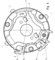
Figur 5 ist eine Draufsicht auf die erfindungsgemäße Bremsanordnung gezeigt. - In der
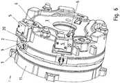
Figur 6 ist eine Schrägansicht auf die erfindungsgemäße Bremsanordnung gezeigt. - In der
Figur 7 ist eine Schrägansicht auf die Schalteinheit 5 und das Halteteil 20 gezeigt zusammen mit dem Übertragungsmittel. - In der
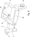
Figur 8 ist eine Schrägansicht auf die Schalteinheit 5 und das Halteteil 20 gezeigt zusammen mit dem Übertragungsmittel, wobei eine Ausnehmung 80 die elastische Auslenkbarkeit der Zunge 30 verbessert. - In
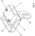
Figur 9 ist ein Ausführungsbeispiel mit zweiteilig ausgeführtem Halteteil gezeigt. - Wie in
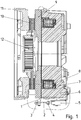
Figur 1 gezeigt, weist die erfindungsgemäße Bremsanordnung einen Spulenkern 7 auf, der eine ringförmige Ausnehmung aufweist, in welcher eine Spule 8, insbesondere Ringwicklung, aufgenommen ist. - Bei Bestromung der Spule 8 wird eine Ankerscheibe 9 zum Spulenkern 7 hin entgegen der Federkraft von sich am Spulenkern 7 abstützenden Federelementen gezogen, so dass die als Federdruckbremse ausgeführte Bremsanordnung gelüftet wird.
- Die Ankerscheibe 9 ist drehfest aber axial verschiebbar mit dem Spulenkern 7 verbunden.
- Der Belagträger 10 weist axial beidseitig einen Bremsbelag auf und ist mittels einer an ihm vorgesehenen oder mit ihm verbundenen Innenverzahnung drehfest aber axial verschieblich mit einer Außenverzahnung, also Mitnehmerverzahnung 12, der abzubremsenden Welle verbunden.
- Beim Nicht-Bestromen der Spule 8 drücken die an dem Spulenkern 7 abgestützten Federelemente die Ankerscheibe 9 axial weg von dem Spulenkern 7 auf den Belagträger 10, der mit seiner Innenverzahnung auf der mit der Innenverzahnung im Eingriff stehenden Außenverzahnung axial auf die Bremsfläche gedrückt wird. Somit wird der der Ankerscheibe 9 zugewandt angeordnete Bremsbelag des Bremsbelagträgers 10 auf die Ankerscheibe gedrückt und der andere Bremsbelag auf die Bremsfläche.
- Die Bremsfläche ist auf einem Gehäuseteil angeordnet, welches mit dem Spulenkern 7 fest verbunden ist. Das Gehäuseteil ist vorzugsweise ein Lagerschild eines Elektromotors, dessen Rotorwelle in diesem Lagerschild mittels dort aufgenommenem Lager gelagert ist und die von der Bremsanordnung abzubremsende Welle ist.
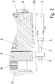
- Zur Funktionsüberwachung und zur Verschleißüberwachung ist jeweils eine Schalteinheit 5 an der Bremsanordnung vorgesehen.
- Ein Bolzen 1 ist in einer Radialbohrung der Ankerscheibe 9 vorgesehen und mit der Ankerscheibe 9 verbunden, insbesondere eingepresst, klebeverbunden und/oder schweißverbunden.
- In den radial von der Ankerscheibe 9 hervorstehenden Bolzen 1 ist eine Schraube 2 mit ihrem Gewindebereich in eine Gewindebohrung des Bolzens 1 eingeschraubt, die in axialer Richtung ausgerichtet ist. Auf der vom Schraubenkopf 4 der Schraube 2 abgewandten Seite der Gewindebohrung ist eine Kontermutter 3 angeordnet und gegen den Bolzen 1 angezogen.
- Die Schalteinheit 5 ist an einem Halteteil 20 angeschraubt, welches mittels einer Schraube 6 mit dem Spulenkern 7 schraubverbunden ist.
- Das Halteteil ist vorzugsweise als Blechteil, insbesondere als Stanz-Biegeteil, hergestellt.
- Das Halteteil 20 weist eine Zunge 30 auf, die elastisch auslenkbar ist, insbesondere in axialer Richtung. Hierzu drückt abhängig vom axialen Hub, also abhängig von der jeweiligen axialen Position der Ankerscheibe 9, der Schraubenkopf 4 der Schraube 2 auf die Zunge 30.
- Dabei ist der Abstand zwischen Zungengelenkbereich und dem Berührbereich zwischen dem Schraubenkopf 4 und der Zunge 30 kleiner als der Abstand zwischen dem Zungengelenkbereich und einem an der Schalteinheit 5 angeordneten Druckschaltkopf 31.
- Somit wird also der vom Schraubenkopf 4 zurückgelegte Hub verstärkt, so dass der auf den Druckschaltkopf 31 drückende Bereich der Zunge 30 einen entsprechend dem Hebelweg der Zunge 30 vergrößerten axialen Hub. Somit wird der Druckschaltkopf 31 von der Zunge 30 abhängig von der Position des Schraubenkopfes 4 eingedrückt zur Schalteinheit 5 hin, die somit bei Erreichen einer kritischen Position ausgelöst wird, also schaltet.
- Mittels der Zunge 30 wird also der Hub der Ankerscheibe vergrößert, um ein sicheres Betätigen des Druckschaltkopfes 31 zu bewirken bei Erreichen der kritischen Axialposition.
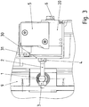
- Wie in
Figur 5 und inFigur 6 gezeigt, sind an der Bremsanordnung zwei Schalteinheiten in derselben beschriebenen Weise über Halteteile befestigt und deren jeweiliger Druckschaltkopf 31 betätigt unter Verwendung einer jeweiligen Zunge 30 des jeweiligen Halteteils 20. Die jeweilige Schraube 2 ist verschieden weit eingeschraubt in den Bolzen 1. Somit ist mit der ersten Schalteinheit 5 die Funktion der Bremse, also das Lüften beziehungsweise Einfallen Detektierbar, und mit der zweiten Schalteinheit 5 der Verschleiß überwachbar. - Die Schalteinheiten 5 sind in Umfangsrichtung beabstandet.
- Die Ankerscheibe 9 ist aus einem ferromagnetischen Material, vorzugswiese Stahl.
- Der Spulenkern 7 ist aus einem ferromagnetischen Stahlguss gefertigt, vorzugsweise ein GGG-Guss.
- Wie in
Figur 7 deutlich gezeigt, ist die Schalteinheit 5 an dem Halteteil 20 mittels Schrauben 70 befestigt, die im Wesentlichen in radialer Richtung mit ihrer Schraubenachse ausgerichtet sind. - Die Schraube 6 zur Befestigung des Halteteils 20 am Spulenkern 7 ist in axialer Richtung ausgerichtet, weil sie durch eine Ausnehmung einer heruntergebogenen Lasche, insbesondere um 90° heruntergebogenen Lasche, des Halteteils 20 geführt ist.
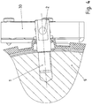
- Wie in
Figur 8 gezeigt, wird die Auslenkbarkeit der Zunge 30 durch eine im Gelenkbereich der Zunge 30 angeordnete Ausnehmung 80 verbessert. Die dadurch bewirkte Erhöhung der Biegsamkeit, also der Elastizität in diesem Bereich, ist alternativ oder zusätzlich durch eine Verengung und/oder durch eine Wandstärkeverdünnung in diesem Beriech, insbesondere im Vergleich zu einem Bereich der Zunge 30, erreichbar beziehungsweise verbesserbar. - Wie in
Figur 9 gezeigt, ist das Halteteil 20 auch als zweigeteilt ausgeführtes Halteteil ausführbar. Dabei weist das Halteteil ein Unterteil 90 und ein Oberteil 91 auf. Unterteil 90 und Oberteil 91 sind jeweils als Stanz-Biegeteil ausgeführt, weisen aber zueinander unterschiedliche Blechstärken auf. Somit ist die Elastizität der Zunge 30 durch entsprechend dünnwandiges Ausführen des Oberteils 91 erhöht und trotzdem eine stabile Halterung mittels des Unterteils 90 erreichbar. - Mittels der Schrauben 70 werden Unterteil 90, Oberteil 91 und Schalteinheit 5 verbunden.
- Das Unterteil 90 ist mittels einer Schraube 6 mit dem Spulenkern 7 schraubverbunden.
-
- 1 Bolzen
- 2 Schraube mit Schraubkopf 4
- 3 Kontermutter
- 4 Schraubkopf der Schraube 2
- 5 Schalteinheit
- 6 Schraube
- 7 Spulenkern
- 8 Spule, insbesondere Ringwicklung
- 9 Ankerscheibe
- 10 Belagträger
- 11 Gehäuseteil mit Bremsfläche, insbesondere Lagerschild mit Bremsfläche
- 12 Mitnehmerverzahnung
- 20 Halteteil, insbesondere Stanz-Biegeteil
- 30 Zunge des Halteteils 20
- 31 Druckschaltkopf
- 70 Schraube
- 80 Ausnehmung
- 90 Unterteil des Halteteils
- 91 Oberteil des Halteteils
Claims (14)
- Bremsanordnung, insbesondere aufweisend eine elektromagnetisch betätigbare Federdruckbremse,
wobei eine Ankerscheibe (3) verschiebbar, insbesondere axial verschiebbar, angeordnet ist,
insbesondere drehfest verbunden ist mit einem Spulenkern einer Wicklung, insbesondere einer Bremsspule,
wobei eine Schalteinheit (5) einen verschiebbaren Druckschaltkopf (31) aufweist, mit dem die Schalteinheit betätigbar ist,
dadurch gekennzeichnet, dass
die Schalteinheit, insbesondere das Gehäuse der Schalteinheit, mit einem Halteteil (20) verbunden ist, an welchem eine elastisch auslenkbare Zunge (30), insbesondere eine gegenüber dem Gehäuse der Schalteinheit elastisch auslenkbare Zunge angeordnet ist, insbesondere ausgeformt ist,
wobei eine Übertragungseinheit an der Ankerscheibe verbunden ist und die Zunge an einem ersten Bereich berührt und auslenkt
wobei die Zunge (30) den Druckschaltkopf (31) an einem vom ersten Bereich beabstandeten zweiten Bereich berührt. - Bremsanordnung nach Anspruch 1,
dadurch gekennzeichnet, dass
eine weitere, in Umfangsrichtung zur erstgenannten beabstandete Schalteinheit vorgesehen ist, wobei jede der beiden Schalteinheiten einen jeweiligen verschiebbaren Druckschaltkopf aufweist, mit dem die jeweilige Schalteinheit betätigbar ist,
wobei die weitere Schalteinheit, insbesondere das Gehäuse der weiteren Schalteinheit, mit einem weiteren Halteteil verbunden ist, an welchem eine weitere elastisch auslenkbare Zunge, insbesondere eine gegenüber dem weiteren Gehäuse der weiteren Schalteinheit elastisch auslenkbare Zunge angeordnet ist, insbesondere ausgeformt ist,
wobei eine weitere Übertragungseinheit an der Ankerscheibe verbunden ist und die weitere Zunge an einem weiteren ersten Bereich berührt und auslenkt
wobei die weitere Zunge den jeweiligen Druckschaltkopf an einem vom weitere ersten Bereich beabstandeten weiteren zweiten Bereich berührt. - Bremsanordnung nach mindestens einem der vorangegangenen Ansprüche,
dadurch gekennzeichnet, dass
die Zunge (30) an einem als Gelenk wirksamen Bereich mit dem restlichen Halteteil verbunden ist, insbesondere wobei der als Gelenk wirksame Bereich als Drehgelenk ausgeführt ist oder wobei er einteilig und/oder einstückig am Halteteil ausgebildet ist, insbesondere als Stanz-Biegeteil,
insbesondere wobei im als Gelenk wirksamen Bereich eine Materialverdünnung ausgeformt ist, insbesondere eine Verengung und/oder eine Wandstärkeverdünnung und/oder eine Ausnehmung (80) ausgestanzt ist, insbesondere so dass die Materialverdünnung in diesem Bereich eine höhere elastische Biegsamkeit bewirkt im Vergleich zu einem Bereich der Zunge. - Bremsanordnung nach mindestens einem der vorangegangenen Ansprüche,
dadurch gekennzeichnet, dass
das Halteteil ein Stanz-Biegeteil ist. - Bremsanordnung nach mindestens einem der vorangegangenen Ansprüche,
dadurch gekennzeichnet, dass
die Zunge (30) den Hub der Ankerscheibe vergrößert, indem der zweite Bereich weiter entfernt ist vom als Gelenk wirksamen Bereich als der erste Bereich. - Bremsanordnung nach mindestens einem der vorangegangenen Ansprüche,
dadurch gekennzeichnet, dass
die Übertragungseinheit einen Bolzen (1) aufweist, der formschlüssig mit der Ankerscheibe (9) verbunden ist, insbesondere eingepresst, eingeschraubt und/oder geschweißt,
wobei in eine Gewindebohrung des Bolzens eine Schraube eingeschraubt ist, insbesondere die mit einer Kontermutter (3) am Bolzen fixiert ist,
wobei der Schraubenkopf der Schraube die Zunge berührt, insbesondere im ersten Bereich. - Bremsanordnung nach mindestens einem der vorangegangenen Ansprüche,
dadurch gekennzeichnet, dass
die Verschiebungsrichtung der Ankerscheibe (9) und die Betätigungsrichtung des Druckschaltkopfes parallel angeordnet sind. - Bremsanordnung nach mindestens einem der vorangegangenen Ansprüche,
dadurch gekennzeichnet, dass der Bolzen (1) radial ausgerichtet ist, wobei die axiale Richtung von der Wellenachse der von der Bremsanordnung abzubremsenden beziehungsweise abgebremsten Welle, insbesondere Rotorwelle eines Elektromotors, definiert ist. - Bremsanordnung nach mindestens einem der vorangegangenen Ansprüche,
dadurch gekennzeichnet, dass
die Schraubenachse der Schraube (2) in axialer Richtung ausgerichtet ist, insbesondere wobei die Zunge im Wesentlichen in axialer Richtung auslenkbar ist. - Bremsanordnung nach mindestens einem der vorangegangenen Ansprüche,
dadurch gekennzeichnet, dass
die von der Bremsanordnung abzubremsende Welle eine Außenverzahnung aufweist, mit welcher die Innenverzahnung (12) eines Bremsbelagträgers im Eingriff steht, so dass dieser axial verschiebbar aber drehfest mit der Welle verbunden ist,
wobei der Bremsbelagträger (10) axial auf der von der Ankerscheibe abgewandten Seite angeordnet ist,
wobei der Bremsbelagträger axial zwischen Ankerscheibe und einem eine Bremsfläche aufweisenden Teil angeordnet ist, insbesondere wobei das Teil ein Gehäuseteil eines Elektromotors ist, insbesondere ein Lagerschild, welches ein Lager der Welle aufnimmt,
wobei Federelemente zwischen Ankerscheibe und Spulenkern (7) angeordnet sind, so dass bei Bestromung der im Spulenkern aufgenommenen Wicklung, insbesondere in einem ringförmigen Ausnehmung aufgenommenen Ringwicklung, die Ankerscheibe entgegen der von den Federelementen erzeugten Federkraft zum Spulenkern hin verschoben wird. - Bremsanordnung nach mindestens einem der vorangegangenen Ansprüche,
dadurch gekennzeichnet, dass
das Halteteil (20) zumindest zweiteilig ausgeführt ist, insbesondere also aus mindestens zwei Teilen. - Bremsanordnung nach Anspruch 11, dadurch gekennzeichnet, dass
die zumindest zwei Teile zueinander unterschiedliche Wandstärke aufweisen. - Bremsanordnung nach mindestens einem der Ansprüche 11 oder 12, dadurch gekennzeichnet, dass
die zumindest zwei Teile des Halteteils (20) Stanz-Biegeteile sind, insbesondere mit jeweils unterschiedlicher Blechwandstärke. - Bremsanordnung nach mindestens einem der Ansprüche 11 bis 13, dadurch gekennzeichnet, dass
an einem ersten Teil, insbesondere Oberteil (91), die Zunge ausgebildet ist und ein oder das andere Teil, insbesondere Unterteil (90) eine größere Wandstärke, insbesondere Blechwandstärke, aufweist als das Oberteil (91).
Applications Claiming Priority (2)
| Application Number | Priority Date | Filing Date | Title |
|---|---|---|---|
| DE102013003372 | 2013-03-01 | ||
| PCT/EP2014/000065 WO2014131482A1 (de) | 2013-03-01 | 2014-01-14 | Elektromagnetisch betätigbare federdruckbremse |
Publications (2)
| Publication Number | Publication Date |
|---|---|
| EP2962008A1 EP2962008A1 (de) | 2016-01-06 |
| EP2962008B1 true EP2962008B1 (de) | 2018-09-05 |
Family
ID=49956153
Family Applications (1)
| Application Number | Title | Priority Date | Filing Date |
|---|---|---|---|
| EP14700329.7A Active EP2962008B1 (de) | 2013-03-01 | 2014-01-14 | Elektromagnetisch betätigbare federdruckbremse |
Country Status (3)
| Country | Link |
|---|---|
| EP (1) | EP2962008B1 (de) |
| DE (1) | DE102014000196B4 (de) |
| WO (1) | WO2014131482A1 (de) |
Families Citing this family (4)
| Publication number | Priority date | Publication date | Assignee | Title |
|---|---|---|---|---|
| DE102019120041A1 (de) * | 2019-07-24 | 2021-01-28 | Konecranes Global Corp. | Elektromagnetische Bremse |
| WO2022171358A1 (de) | 2021-02-10 | 2022-08-18 | Sew-Eurodrive Gmbh & Co. Kg Abt. Ecg | Elektromotor mit elektromagnetisch betätigbarer bremse |
| DE102022116653A1 (de) * | 2022-07-05 | 2024-01-11 | Weiss Gmbh | Verfahren zum Betrieb eines Schwenkantriebs |
| WO2026057322A1 (de) | 2024-09-12 | 2026-03-19 | Sew-Eurodrive Gmbh & Co Kg | Elektromagnetisch betätigbare bremsanordnung mit einer abzubremsenden welle |
Family Cites Families (10)
| Publication number | Priority date | Publication date | Assignee | Title |
|---|---|---|---|---|
| US3038576A (en) | 1960-05-24 | 1962-06-12 | Siegler Corp | Torque limiting and overload sensing device |
| US4020454A (en) * | 1976-02-17 | 1977-04-26 | Malonee Arley L | Brake monitoring system |
| DE9216975U1 (de) | 1992-12-12 | 1993-02-11 | Binder Magnete GmbH, 7730 Villingen-Schwenningen | Elektromagnetisch betätigbare Vorrichtung zur Kraftübertragung |
| US5421436A (en) * | 1994-02-17 | 1995-06-06 | Rexnord Corporation | Orientation-free brake mechanism |
| DE29510246U1 (de) | 1995-06-23 | 1995-08-24 | Chr. Mayr Gmbh + Co Kg, 87665 Mauerstetten | Elektrisch betätigte Bremse, insbesondere Reibungsbremse |
| DE20302055U1 (de) | 2003-02-10 | 2003-04-10 | Chr. Mayr GmbH & Co. KG, 87665 Mauerstetten | Mikroschalter mit integrierter Hebelübersetzung |
| DE202004007282U1 (de) | 2004-05-07 | 2004-07-22 | Chr. Mayr Gmbh & Co. Kg | Elektromagnetisch gelüftete Zweikreis-Anbaubremse mit ins Lagerschild integrierten Magnetspulen und Druckfederanordnung |
| DE102006004065A1 (de) | 2006-01-28 | 2007-08-02 | Jungheinrich Ag | Federspeicherbremse für ein Flurförderzeug |
| DE102008046535A1 (de) | 2008-09-10 | 2010-03-11 | Chr. Mayr Gmbh + Co Kg | Doppelsegmentbremse |
| DE202011005655U1 (de) * | 2011-04-28 | 2011-07-13 | Chr. Mayr Gmbh & Co. Kg | Verbesserte Schaltzustandsüberwachung für Federdruckbremsen |
-
2014
- 2014-01-14 DE DE102014000196.2A patent/DE102014000196B4/de active Active
- 2014-01-14 WO PCT/EP2014/000065 patent/WO2014131482A1/de not_active Ceased
- 2014-01-14 EP EP14700329.7A patent/EP2962008B1/de active Active
Also Published As
| Publication number | Publication date |
|---|---|
| DE102014000196A1 (de) | 2014-09-04 |
| DE102014000196B4 (de) | 2020-07-09 |
| EP2962008A1 (de) | 2016-01-06 |
| WO2014131482A1 (de) | 2014-09-04 |
| WO2014131482A8 (de) | 2014-11-20 |
Similar Documents
| Publication | Publication Date | Title |
|---|---|---|
| EP2006563B1 (de) | Automatische Federspeicherbremse für Flurförderzeug | |
| DE102017000845B4 (de) | Elektromagnetisch betätigbare Bremsanordnung zum Abbremsen einer Welle und Elektromotor mit einer solchen Bremsanordnung | |
| DE102014018485B3 (de) | Eletromagnetisch betätigbare Bremsvorrichtung | |
| EP2926021B1 (de) | Bremsanordnung und elektromotor | |
| DE102012019415B4 (de) | Elektromotor, insbesondere mit einer redundanten Bremsanordnung | |
| EP2926020B1 (de) | Bremsanordnung und elektromotor | |
| EP2962008B1 (de) | Elektromagnetisch betätigbare federdruckbremse | |
| DE102015001647B4 (de) | Bremsanordnung | |
| DE102013001899B4 (de) | Bremsanordnung | |
| EP3080474B1 (de) | Elektromagnetisch betätigbare bremsanordnung und elektromotor mit einer bremsanordnung | |
| EP2901037B1 (de) | Bremsanordnung und elektromotor mit einer bremsanordnung | |
| DE102018006725A1 (de) | Elektromagnetisch betätigbare Bremsanordnung und Verfahren zur Inbetriebnahme oder Wartung einer elektromagnetisch betätigbaren Bremsanordnung | |
| DE102012018998B4 (de) | Elektromagnetisch betätigbare Bremsanordnung und Elektromotor | |
| EP3256750B1 (de) | Bremsanordnung mit einem bremsbelagträger und einem mitnehmer | |
| EP3788271B1 (de) | Elektromotor mit einer kupplung zwischen der rotorwelle und der welle eines winkelsensors | |
| EP2761199A1 (de) | Scheibenbremse für ein nutzfahrzeug | |
| DE102016012643B4 (de) | Elektromagnetisch betätigbare Bremsanordnung | |
| DE102025133801A1 (de) | Elektromagnetisch betätigbare Bremsanordnung mit einer abzubremsenden Welle | |
| DE102011119604A1 (de) | Bremsanordnung | |
| DE102017009332A1 (de) | Elektromagnetisch betätigbare Bremsanordnung und Verfahren zur Inbetriebnahme oder Wartung einer elektromagnetisch betätigbaren Bremsanordnung |
Legal Events
| Date | Code | Title | Description |
|---|---|---|---|
| PUAI | Public reference made under article 153(3) epc to a published international application that has entered the european phase |
Free format text: ORIGINAL CODE: 0009012 |
|
| 17P | Request for examination filed |
Effective date: 20151001 |
|
| AK | Designated contracting states |
Kind code of ref document: A1 Designated state(s): AL AT BE BG CH CY CZ DE DK EE ES FI FR GB GR HR HU IE IS IT LI LT LU LV MC MK MT NL NO PL PT RO RS SE SI SK SM TR |
|
| AX | Request for extension of the european patent |
Extension state: BA ME |
|
| DAX | Request for extension of the european patent (deleted) | ||
| GRAP | Despatch of communication of intention to grant a patent |
Free format text: ORIGINAL CODE: EPIDOSNIGR1 |
|
| STAA | Information on the status of an ep patent application or granted ep patent |
Free format text: STATUS: GRANT OF PATENT IS INTENDED |
|
| INTG | Intention to grant announced |
Effective date: 20180502 |
|
| GRAS | Grant fee paid |
Free format text: ORIGINAL CODE: EPIDOSNIGR3 |
|
| GRAA | (expected) grant |
Free format text: ORIGINAL CODE: 0009210 |
|
| STAA | Information on the status of an ep patent application or granted ep patent |
Free format text: STATUS: THE PATENT HAS BEEN GRANTED |
|
| AK | Designated contracting states |
Kind code of ref document: B1 Designated state(s): AL AT BE BG CH CY CZ DE DK EE ES FI FR GB GR HR HU IE IS IT LI LT LU LV MC MK MT NL NO PL PT RO RS SE SI SK SM TR |
|
| REG | Reference to a national code |
Ref country code: GB Ref legal event code: FG4D Free format text: NOT ENGLISH |
|
| REG | Reference to a national code |
Ref country code: CH Ref legal event code: EP Ref country code: CH Ref legal event code: NV Representative=s name: HEPP WENGER RYFFEL AG, CH |
|
| REG | Reference to a national code |
Ref country code: AT Ref legal event code: REF Ref document number: 1038175 Country of ref document: AT Kind code of ref document: T Effective date: 20180915 |
|
| REG | Reference to a national code |
Ref country code: DE Ref legal event code: R096 Ref document number: 502014009373 Country of ref document: DE |
|
| REG | Reference to a national code |
Ref country code: IE Ref legal event code: FG4D Free format text: LANGUAGE OF EP DOCUMENT: GERMAN |
|
| REG | Reference to a national code |
Ref country code: SE Ref legal event code: TRGR |
|
| REG | Reference to a national code |
Ref country code: NL Ref legal event code: FP |
|
| REG | Reference to a national code |
Ref country code: LT Ref legal event code: MG4D |
|
| PG25 | Lapsed in a contracting state [announced via postgrant information from national office to epo] |
Ref country code: GR Free format text: LAPSE BECAUSE OF FAILURE TO SUBMIT A TRANSLATION OF THE DESCRIPTION OR TO PAY THE FEE WITHIN THE PRESCRIBED TIME-LIMIT Effective date: 20181206 Ref country code: NO Free format text: LAPSE BECAUSE OF FAILURE TO SUBMIT A TRANSLATION OF THE DESCRIPTION OR TO PAY THE FEE WITHIN THE PRESCRIBED TIME-LIMIT Effective date: 20181205 Ref country code: LT Free format text: LAPSE BECAUSE OF FAILURE TO SUBMIT A TRANSLATION OF THE DESCRIPTION OR TO PAY THE FEE WITHIN THE PRESCRIBED TIME-LIMIT Effective date: 20180905 Ref country code: BG Free format text: LAPSE BECAUSE OF FAILURE TO SUBMIT A TRANSLATION OF THE DESCRIPTION OR TO PAY THE FEE WITHIN THE PRESCRIBED TIME-LIMIT Effective date: 20181205 Ref country code: FI Free format text: LAPSE BECAUSE OF FAILURE TO SUBMIT A TRANSLATION OF THE DESCRIPTION OR TO PAY THE FEE WITHIN THE PRESCRIBED TIME-LIMIT Effective date: 20180905 Ref country code: RS Free format text: LAPSE BECAUSE OF FAILURE TO SUBMIT A TRANSLATION OF THE DESCRIPTION OR TO PAY THE FEE WITHIN THE PRESCRIBED TIME-LIMIT Effective date: 20180905 |
|
| PG25 | Lapsed in a contracting state [announced via postgrant information from national office to epo] |
Ref country code: LV Free format text: LAPSE BECAUSE OF FAILURE TO SUBMIT A TRANSLATION OF THE DESCRIPTION OR TO PAY THE FEE WITHIN THE PRESCRIBED TIME-LIMIT Effective date: 20180905 Ref country code: AL Free format text: LAPSE BECAUSE OF FAILURE TO SUBMIT A TRANSLATION OF THE DESCRIPTION OR TO PAY THE FEE WITHIN THE PRESCRIBED TIME-LIMIT Effective date: 20180905 Ref country code: HR Free format text: LAPSE BECAUSE OF FAILURE TO SUBMIT A TRANSLATION OF THE DESCRIPTION OR TO PAY THE FEE WITHIN THE PRESCRIBED TIME-LIMIT Effective date: 20180905 |
|
| PG25 | Lapsed in a contracting state [announced via postgrant information from national office to epo] |
Ref country code: PL Free format text: LAPSE BECAUSE OF FAILURE TO SUBMIT A TRANSLATION OF THE DESCRIPTION OR TO PAY THE FEE WITHIN THE PRESCRIBED TIME-LIMIT Effective date: 20180905 Ref country code: EE Free format text: LAPSE BECAUSE OF FAILURE TO SUBMIT A TRANSLATION OF THE DESCRIPTION OR TO PAY THE FEE WITHIN THE PRESCRIBED TIME-LIMIT Effective date: 20180905 Ref country code: ES Free format text: LAPSE BECAUSE OF FAILURE TO SUBMIT A TRANSLATION OF THE DESCRIPTION OR TO PAY THE FEE WITHIN THE PRESCRIBED TIME-LIMIT Effective date: 20180905 Ref country code: IS Free format text: LAPSE BECAUSE OF FAILURE TO SUBMIT A TRANSLATION OF THE DESCRIPTION OR TO PAY THE FEE WITHIN THE PRESCRIBED TIME-LIMIT Effective date: 20190105 Ref country code: CZ Free format text: LAPSE BECAUSE OF FAILURE TO SUBMIT A TRANSLATION OF THE DESCRIPTION OR TO PAY THE FEE WITHIN THE PRESCRIBED TIME-LIMIT Effective date: 20180905 Ref country code: RO Free format text: LAPSE BECAUSE OF FAILURE TO SUBMIT A TRANSLATION OF THE DESCRIPTION OR TO PAY THE FEE WITHIN THE PRESCRIBED TIME-LIMIT Effective date: 20180905 |
|
| PG25 | Lapsed in a contracting state [announced via postgrant information from national office to epo] |
Ref country code: SM Free format text: LAPSE BECAUSE OF FAILURE TO SUBMIT A TRANSLATION OF THE DESCRIPTION OR TO PAY THE FEE WITHIN THE PRESCRIBED TIME-LIMIT Effective date: 20180905 Ref country code: PT Free format text: LAPSE BECAUSE OF FAILURE TO SUBMIT A TRANSLATION OF THE DESCRIPTION OR TO PAY THE FEE WITHIN THE PRESCRIBED TIME-LIMIT Effective date: 20190105 Ref country code: SK Free format text: LAPSE BECAUSE OF FAILURE TO SUBMIT A TRANSLATION OF THE DESCRIPTION OR TO PAY THE FEE WITHIN THE PRESCRIBED TIME-LIMIT Effective date: 20180905 |
|
| REG | Reference to a national code |
Ref country code: DE Ref legal event code: R097 Ref document number: 502014009373 Country of ref document: DE |
|
| PLBE | No opposition filed within time limit |
Free format text: ORIGINAL CODE: 0009261 |
|
| STAA | Information on the status of an ep patent application or granted ep patent |
Free format text: STATUS: NO OPPOSITION FILED WITHIN TIME LIMIT |
|
| PG25 | Lapsed in a contracting state [announced via postgrant information from national office to epo] |
Ref country code: DK Free format text: LAPSE BECAUSE OF FAILURE TO SUBMIT A TRANSLATION OF THE DESCRIPTION OR TO PAY THE FEE WITHIN THE PRESCRIBED TIME-LIMIT Effective date: 20180905 |
|
| 26N | No opposition filed |
Effective date: 20190606 |
|
| PG25 | Lapsed in a contracting state [announced via postgrant information from national office to epo] |
Ref country code: MC Free format text: LAPSE BECAUSE OF FAILURE TO SUBMIT A TRANSLATION OF THE DESCRIPTION OR TO PAY THE FEE WITHIN THE PRESCRIBED TIME-LIMIT Effective date: 20180905 Ref country code: SI Free format text: LAPSE BECAUSE OF FAILURE TO SUBMIT A TRANSLATION OF THE DESCRIPTION OR TO PAY THE FEE WITHIN THE PRESCRIBED TIME-LIMIT Effective date: 20180905 |
|
| PG25 | Lapsed in a contracting state [announced via postgrant information from national office to epo] |
Ref country code: LU Free format text: LAPSE BECAUSE OF NON-PAYMENT OF DUE FEES Effective date: 20190114 |
|
| REG | Reference to a national code |
Ref country code: BE Ref legal event code: MM Effective date: 20190131 |
|
| REG | Reference to a national code |
Ref country code: IE Ref legal event code: MM4A |
|
| PG25 | Lapsed in a contracting state [announced via postgrant information from national office to epo] |
Ref country code: BE Free format text: LAPSE BECAUSE OF NON-PAYMENT OF DUE FEES Effective date: 20190131 |
|
| PG25 | Lapsed in a contracting state [announced via postgrant information from national office to epo] |
Ref country code: IE Free format text: LAPSE BECAUSE OF NON-PAYMENT OF DUE FEES Effective date: 20190114 |
|
| PG25 | Lapsed in a contracting state [announced via postgrant information from national office to epo] |
Ref country code: TR Free format text: LAPSE BECAUSE OF FAILURE TO SUBMIT A TRANSLATION OF THE DESCRIPTION OR TO PAY THE FEE WITHIN THE PRESCRIBED TIME-LIMIT Effective date: 20180905 |
|
| PG25 | Lapsed in a contracting state [announced via postgrant information from national office to epo] |
Ref country code: MT Free format text: LAPSE BECAUSE OF FAILURE TO SUBMIT A TRANSLATION OF THE DESCRIPTION OR TO PAY THE FEE WITHIN THE PRESCRIBED TIME-LIMIT Effective date: 20180905 |
|
| PG25 | Lapsed in a contracting state [announced via postgrant information from national office to epo] |
Ref country code: CY Free format text: LAPSE BECAUSE OF FAILURE TO SUBMIT A TRANSLATION OF THE DESCRIPTION OR TO PAY THE FEE WITHIN THE PRESCRIBED TIME-LIMIT Effective date: 20180905 |
|
| PG25 | Lapsed in a contracting state [announced via postgrant information from national office to epo] |
Ref country code: HU Free format text: LAPSE BECAUSE OF FAILURE TO SUBMIT A TRANSLATION OF THE DESCRIPTION OR TO PAY THE FEE WITHIN THE PRESCRIBED TIME-LIMIT; INVALID AB INITIO Effective date: 20140114 |
|
| PG25 | Lapsed in a contracting state [announced via postgrant information from national office to epo] |
Ref country code: MK Free format text: LAPSE BECAUSE OF FAILURE TO SUBMIT A TRANSLATION OF THE DESCRIPTION OR TO PAY THE FEE WITHIN THE PRESCRIBED TIME-LIMIT Effective date: 20180905 |
|
| PGFP | Annual fee paid to national office [announced via postgrant information from national office to epo] |
Ref country code: CH Payment date: 20250221 Year of fee payment: 12 |
|
| PGFP | Annual fee paid to national office [announced via postgrant information from national office to epo] |
Ref country code: GB Payment date: 20251204 Year of fee payment: 13 |
|
| PGFP | Annual fee paid to national office [announced via postgrant information from national office to epo] |
Ref country code: FR Payment date: 20251208 Year of fee payment: 13 Ref country code: NL Payment date: 20251215 Year of fee payment: 13 |
|
| PGFP | Annual fee paid to national office [announced via postgrant information from national office to epo] |
Ref country code: SE Payment date: 20251210 Year of fee payment: 13 |
|
| REG | Reference to a national code |
Ref country code: CH Ref legal event code: U11 Free format text: ST27 STATUS EVENT CODE: U-0-0-U10-U11 (AS PROVIDED BY THE NATIONAL OFFICE) Effective date: 20260201 |
|
| PGFP | Annual fee paid to national office [announced via postgrant information from national office to epo] |
Ref country code: DE Payment date: 20260131 Year of fee payment: 13 |
|
| PGFP | Annual fee paid to national office [announced via postgrant information from national office to epo] |
Ref country code: AT Payment date: 20260109 Year of fee payment: 13 |
|
| PGFP | Annual fee paid to national office [announced via postgrant information from national office to epo] |
Ref country code: IT Payment date: 20251219 Year of fee payment: 13 |