EP1925813A1 - Kraftstoffinjektor mit einer Messeinrichtung - Google Patents
Kraftstoffinjektor mit einer Messeinrichtung Download PDFInfo
- Publication number
- EP1925813A1 EP1925813A1 EP07115363A EP07115363A EP1925813A1 EP 1925813 A1 EP1925813 A1 EP 1925813A1 EP 07115363 A EP07115363 A EP 07115363A EP 07115363 A EP07115363 A EP 07115363A EP 1925813 A1 EP1925813 A1 EP 1925813A1
- Authority
- EP
- European Patent Office
- Prior art keywords
- movement
- fuel injector
- injector
- nozzle needle
- measuring device
- Prior art date
- Legal status (The legal status is an assumption and is not a legal conclusion. Google has not performed a legal analysis and makes no representation as to the accuracy of the status listed.)
- Granted
Links
- 239000000446 fuel Substances 0.000 title claims abstract description 71
- 230000033001 locomotion Effects 0.000 claims abstract description 91
- 238000002485 combustion reaction Methods 0.000 claims abstract description 24
- 230000001939 inductive effect Effects 0.000 claims abstract description 5
- 238000000034 method Methods 0.000 claims abstract description 5
- 230000005291 magnetic effect Effects 0.000 claims description 25
- 238000002347 injection Methods 0.000 claims description 18
- 239000007924 injection Substances 0.000 claims description 18
- 238000007789 sealing Methods 0.000 claims description 10
- 239000000463 material Substances 0.000 claims description 6
- 230000000737 periodic effect Effects 0.000 claims description 4
- 239000002131 composite material Substances 0.000 claims description 2
- 239000000843 powder Substances 0.000 claims description 2
- 229910000859 α-Fe Inorganic materials 0.000 claims description 2
- 230000005284 excitation Effects 0.000 claims 1
- 238000006073 displacement reaction Methods 0.000 abstract 2
- 238000012986 modification Methods 0.000 abstract 1
- 230000004048 modification Effects 0.000 abstract 1
- 238000005259 measurement Methods 0.000 description 11
- 238000010586 diagram Methods 0.000 description 6
- 239000012530 fluid Substances 0.000 description 3
- 239000011521 glass Substances 0.000 description 3
- 238000002844 melting Methods 0.000 description 3
- 230000008018 melting Effects 0.000 description 3
- 238000001514 detection method Methods 0.000 description 2
- XEEYBQQBJWHFJM-UHFFFAOYSA-N Iron Chemical group [Fe] XEEYBQQBJWHFJM-UHFFFAOYSA-N 0.000 description 1
- ZOKXTWBITQBERF-UHFFFAOYSA-N Molybdenum Chemical compound [Mo] ZOKXTWBITQBERF-UHFFFAOYSA-N 0.000 description 1
- 230000001419 dependent effect Effects 0.000 description 1
- 238000013461 design Methods 0.000 description 1
- 238000011161 development Methods 0.000 description 1
- 230000018109 developmental process Effects 0.000 description 1
- 238000011156 evaluation Methods 0.000 description 1
- 238000009434 installation Methods 0.000 description 1
- 239000000696 magnetic material Substances 0.000 description 1
- 229910052750 molybdenum Inorganic materials 0.000 description 1
- 239000011733 molybdenum Substances 0.000 description 1
- 230000003534 oscillatory effect Effects 0.000 description 1
- 238000012827 research and development Methods 0.000 description 1
- 239000000243 solution Substances 0.000 description 1
Images


Classifications
-
- F—MECHANICAL ENGINEERING; LIGHTING; HEATING; WEAPONS; BLASTING
- F02—COMBUSTION ENGINES; HOT-GAS OR COMBUSTION-PRODUCT ENGINE PLANTS
- F02M—SUPPLYING COMBUSTION ENGINES IN GENERAL WITH COMBUSTIBLE MIXTURES OR CONSTITUENTS THEREOF
- F02M65/00—Testing fuel-injection apparatus, e.g. testing injection timing ; Cleaning of fuel-injection apparatus
- F02M65/005—Measuring or detecting injection-valve lift, e.g. to determine injection timing
-
- F—MECHANICAL ENGINEERING; LIGHTING; HEATING; WEAPONS; BLASTING
- F02—COMBUSTION ENGINES; HOT-GAS OR COMBUSTION-PRODUCT ENGINE PLANTS
- F02M—SUPPLYING COMBUSTION ENGINES IN GENERAL WITH COMBUSTIBLE MIXTURES OR CONSTITUENTS THEREOF
- F02M47/00—Fuel-injection apparatus operated cyclically with fuel-injection valves actuated by fluid pressure
- F02M47/02—Fuel-injection apparatus operated cyclically with fuel-injection valves actuated by fluid pressure of accumulator-injector type, i.e. having fuel pressure of accumulator tending to open, and fuel pressure in other chamber tending to close, injection valves and having means for periodically releasing that closing pressure
- F02M47/027—Electrically actuated valves draining the chamber to release the closing pressure
-
- F—MECHANICAL ENGINEERING; LIGHTING; HEATING; WEAPONS; BLASTING
- F02—COMBUSTION ENGINES; HOT-GAS OR COMBUSTION-PRODUCT ENGINE PLANTS
- F02M—SUPPLYING COMBUSTION ENGINES IN GENERAL WITH COMBUSTIBLE MIXTURES OR CONSTITUENTS THEREOF
- F02M63/00—Other fuel-injection apparatus having pertinent characteristics not provided for in groups F02M39/00 - F02M57/00 or F02M67/00; Details, component parts, or accessories of fuel-injection apparatus, not provided for in, or of interest apart from, the apparatus of groups F02M39/00 - F02M61/00 or F02M67/00; Combination of fuel pump with other devices, e.g. lubricating oil pump
- F02M63/0012—Valves
- F02M63/0014—Valves characterised by the valve actuating means
- F02M63/0015—Valves characterised by the valve actuating means electrical, e.g. using solenoid
- F02M63/0026—Valves characterised by the valve actuating means electrical, e.g. using solenoid using piezoelectric or magnetostrictive actuators
-
- F—MECHANICAL ENGINEERING; LIGHTING; HEATING; WEAPONS; BLASTING
- F02—COMBUSTION ENGINES; HOT-GAS OR COMBUSTION-PRODUCT ENGINE PLANTS
- F02M—SUPPLYING COMBUSTION ENGINES IN GENERAL WITH COMBUSTIBLE MIXTURES OR CONSTITUENTS THEREOF
- F02M2200/00—Details of fuel-injection apparatus, not otherwise provided for
- F02M2200/24—Fuel-injection apparatus with sensors
Definitions
- the present invention relates to a fuel injector for an internal combustion engine according to the preamble of claim 1.
- the invention relates to a fuel injector with a measuring device for measuring an opening and closing movement of a moving device in a movement axis.
- Fuel injectors of the type of interest here find particular application in internal combustion engines, which use such injectors to allow a metered injection of the fuel to be burned in an internal combustion engine.
- Internal combustion engines may be embodied with differently designed fuel injectors, fuel injectors being able to be distinguished into those which are referred to as magnetically operated injectors and those which may be referred to as piezoelectrically operated injectors.
- Magnetically operated injectors include an electromagnet which can move an armature and actuate a solenoid valve assembly via a push rod.
- the opening and closing movement of the movement device in this case relates to a valve piston whose stroke movement is transmitted in a movement axis to a nozzle needle.
- the nozzle needle opens and closes the fuel flow through small injection bores which are attached to the nozzle body of the fuel injector and inject the fuel into a combustion chamber.
- piezoelectrically operated injectors have a piezoelectric actuator in order to trigger the opening and closing movement of the nozzle needle via a downstream valve arrangement.
- the movement device in the case of piezoelectrically operated injectors can therefore be limited to the opening and closing movement of the nozzle needle, wherein the movement device carries out an opening and closing movement by means of the valve arrangement arranged downstream of the piezoactuator by a corresponding fluid admission.
- a solenoid operated injector which is designed for an injection system of an internal combustion engine with a solenoid valve, which controls the outflow of fuel through a spillway of a valve control chamber, said solenoid valve means for closing the discharge channel, one of an electromagnet actuated and by the means For closing the drainage channel operatively connected armature and a first valve spring and a second valve spring and a first Hubendanschlag has.
- the first valve spring acts on the armature with a larger spring force in the closing direction, from the closed position of the solenoid valve to reach the first Hubendanschlags the second valve spring acts on the armature in the opening direction with a smaller spring force.
- a respective spring is arranged on each side of the armature in order to build the fuel injector compact and to achieve an improved performance at different frequencies.
- a fuel injector of the type disclosed herein does not offer the ability to measure the movement of the armature to positively influence the possible sensing of the solenoid with the sensed measurement data to optimize performance, particularly with regard to injected fuel quantity and timing of fuel injection ,
- a fuel injector in the manner of a piezoelectrically operated injector.
- the fuel injector relates to a common rail injector for injecting fuel into a combustion chamber of an internal combustion engine.
- the fuel injector includes an injector housing having a fuel inlet communicating with a central fuel high pressure source external to the injector housing and having a pressure space within the injector housing from which high pressure fuel is injected in response to the position of a control valve.
- a lifting movement of a nozzle needle which is guided within a guide bore in a nozzle body. The nozzle needle reaches a Hubendanschlag in the opening time, and may possibly rebound from this or trigger a swinging motion.
- the nozzle needle can trigger a vibration behavior even at the closing time, in which it closes the injection holes in the tip for injecting the fuel into the combustion chamber.
- the vibration behavior is always initiated exactly when the nozzle needle or the Movement device of the fuel injector reaches the Hubendanschlag or the closing seat.
- a check or a feedback of the opening and closing behavior of the nozzle needle for controlling the piezoelectric actuator to trigger the opening and closing movement of the nozzle needle is not possible. Only a driving of the piezoelectric actuator can be changed, wherein a feedback of the opening and closing movement of the nozzle needle can not be evaluated.
- measuring devices for detecting the movement of the movement devices within a fuel injector known, however, which are unsuitable for accurate detection of the time to reach the Hubendanschlags or the end stop in the closing seat of the nozzle needle or the movement device.
- These measuring devices are based on a capacitive distance measurement, which is not suitable for measuring larger strokes of a movement device within a fuel injector.
- the invention includes the technical teaching that the measuring device is designed as an inductive sensor and comprises a measuring body, which at least partially surrounds the movement device in the region of a geometry change formed in the direction of movement, to the end of the injection of the fuel into the combustion chamber and / or the end stop to detect the opening stroke.
- the measuring device is designed as an inductive sensor and comprises a measuring body, which at least partially surrounds the movement device in the region of a geometry change formed in the direction of movement, to the end of the injection of the fuel into the combustion chamber and / or the end stop to detect the opening stroke.
- the proposed embodiment of a fuel injector with a measuring device which operates on the principle of an inductive sensor, offers the advantage that the movement of the moving device in the axis of movement over the entire stroke of the moving device can be detected to both the end of the injection to detect the fuel in the combustion chamber and the end stop or the Hubendanschlag in the opening stroke.
- the partial enclosure of the movement device through the measuring body takes place on a portion of the length of the movement device in the movement axis.
- the measuring body can enclose the movement device on a full circle, wherein the measuring body can also enclose the movement device only on a partial circle, ie on a partial circumference of the movement device.
- the measuring device can provide an electrical signal, from which the end of the injection of the fuel into the combustion chamber and / or the end stop of the opening stroke can be calculated.
- This information can be supplied to the engine control unit, for example, so that the fuel injector can be operated via the injector magnet or via the injector piezoelectric actuator with optimized control signals.
- the measuring body comprises a magnetic yoke
- the fuel injector is designed as a magnetically operated injector, so that according to the design of a magnetically operated injector, the moving means is formed by a valve piston.
- the valve piston performs an axial movement in the direction of the movement axis, wherein the axial movement is introduced by means of a fluid loading in the valve piston, and only the control of the fluid application is generated by an armature plate which is moved by the electromagnet.
- the valve piston performs the same lifting movement, as the nozzle needle of the fuel injector itself also.
- the respective end positions for the end of the injection of the fuel into the combustion chamber or the end stop of the opening stroke of the valve piston also correspond to the end positions of the nozzle needle.
- the location of the arrangement of the measuring device between the nozzle needle and the control valve for the accurate measurement of the lifting movement of the nozzle needle is ultimately not relevant.
- the valve piston comprises a diameter shoulder, which forms the geometry change in the direction of movement of the movement device.
- the change in geometry is important for the measurement principle of the measuring device as an inductive sensor, because only the change in the magnetic inductance causes a change in a measuring signal.
- the change in the magnetic inductance can thus be caused for example by the fact that the magnetic yoke cylindrical iron core formed by the valve piston. If there is a change in the diameter of the valve piston, and the change moves at the height of the magnetic yoke, the magnetic inductance changes, which allows a very precise measurement, since the induced voltage alters equally with the change in the geometrically induced inductance.
- the magnetic yoke may be U-shaped in cross-section, the opening of the U-shape pointing in the direction of the valve piston.
- two poles of the magnetic yoke form, which surround the valve piston annular. If, for example, the diameter jump in the valve piston is at the level of one pole, then the inductance of the magnetic circuit changes depending on the stroke of the valve piston and thus on the stroke of the nozzle needle.
- the fuel injector is designed as a piezoelectrically operated injector with a fluidically actuated nozzle needle, so that the movement device is formed by the nozzle needle itself. Consequently, the measuring body must be arranged in the form of the magnetic yoke in height of the nozzle needle, wherein the nozzle needle is received longitudinally movably in a nozzle body, so that according to a possible embodiment, the measuring device is installed in the nozzle body itself, and the magnetic yoke, the nozzle needle or with the nozzle needle moving parts encloses.
- Piezo-electrically driven injectors do not have a valve piston which extends through the injector itself in an elongated direction. However, an accurate measurement of the stroke of the nozzle needle on or with the nozzle needle itself with the measuring device is possible.
- the nozzle needle adjacent to a nozzle needle control chamber at the end which is sealed with a sealing sleeve, wherein the measuring device is formed by the sealing sleeve and formed in the direction of movement of the movement device geometry change by the adjoining the nozzle needle control chamber end of the nozzle needle.
- the measuring device and the sealing sleeve can be designed to seal the nozzle needle control chamber as the only structural component.
- a quasi - diameter jump serves the end face of the nozzle needle itself, i. There is a "diameter jump to zero".
- the measuring device In order to arrange the measuring device stationary, this is installed either in the injector body or in the nozzle body.
- the injector body and the nozzle body respectively form the holder body fixed part of the injector, wherein the injector body and the nozzle body itself influence the inductance of the measuring device as a magnetic material.
- the field-leading holding body-fixed magnetic core can be radially slotted, wherein the holding body consists for example of the injector body or the nozzle body.
- this is made of a material having a high resistivity. Such materials may involve a powder composite, a ferrite material or the like.
- the measuring device itself comprises a bobbin, which is embedded in the magnetic yoke.
- the bobbin may comprise either a separate exciter and sensor coil, wherein the bobbin may also be formed at the same time as exciter and sensor coil.
- the bobbin on electrical connection lines which must be led out of the receiving area of the measuring device, ie from the injector body or from the nozzle body.
- the sealing of the connecting lines in the body, from which they are led out can be designed in the manner of a glass melting.
- the glass melting of the electrical connection lines from the magnetic yoke and / or from the injector body and / or from the nozzle body takes place, at the same time a corresponding direction can be achieved.
- Particularly advantageous is the choice of contact pins, which has the same coefficient of expansion as the melting glass material, such as molybdenum.
- the present invention further relates to a method for detecting the end of the injection of a fuel into a combustion chamber and / or for detecting the end stop of an opening stroke of a valve piston and / or a nozzle needle with a measuring device.
- the measuring device is described either with a constant electric current or with a constant electrical voltage. If the coil of the measuring device is subjected to a constant current, a voltage is induced during the movement of the valve piston or the nozzle needle, which voltage is, to a first approximation, proportional to the valve piston speed. If, on the other hand, the coil is operated at a constant voltage, essentially a deviation of the current from its value at rest can be measured, the deviation being approximately proportional to the piston speed.
- a very rapid change in the valve piston or nozzle needle speed has quasi a discontinuity the result of the measurement signal by means of which the Hubendanschlags- or closing time can be detected. These times can then be adjusted by a controller by a variation of the corresponding control start and the drive end of the fuel injector to its desired values.
- This controller may for example be part of an engine control unit or be associated with this at least.
- the present method also extends to the fact that a change in the periodic valve piston and / or nozzle needle movement results in a change of the measuring signal output by the measuring device in the form of a discontinuity, and by the discontinuity Hubendanschlags- or closing times of periodically consecutive opening and closing cycles be determined.
- FIG. 1 shows a detail of a fuel injector 1 in a cross-sectional representation. This extends in an elongated direction about a movement axis 2, so that the lifting movement means are movably received in the movement axis 2.
- the liftable movement means for generating an opening and closing movement initially comprise a valve piston 7, which is received longitudinally movable within the injector body 12.
- the valve piston 7 is in operative connection with the likewise received in the movement axis 2 longitudinally movable nozzle needle 9, which is longitudinally movably guided within a nozzle body 13.
- the nozzle body 13 is arranged adjacent to the injector body 12, wherein all the components forming the movement device, such as the valve piston 7 and the nozzle needle 9, are longitudinally movably guided within the same movement axis 2.
- a measuring device 5 concentrically extends around the valve piston 7.
- the injector body 12 is shown as being divided in order to indicate an installation possibility of the measuring device 5. This is accommodated within the injector body 12, so that the measuring device 5 executes no lifting movement and with respect to the valve piston 7 assumes a stationary position.
- the valve piston 7 has a diameter shoulder 8, so that changes due to the different diameter of the valve piston 7, the magnetic circuit in response to the longitudinal position of the valve piston 7 in the direction of the movement axis 2 its inductance.
- the measuring device 5 consists essentially of a magnetic yoke 6, which is annular and has a U-shaped cross-section.
- the opening of the U-shape in this case points inwards in the direction of the valve piston 7, wherein the diameter paragraph 8 adjacent to at least one end of the magnetic yoke 6, to cause a maximum change in the inductance.
- a bobbin 14 is received, which is externally contacted via a connecting line 15. If now the valve piston 7 carries out a lifting movement along the movement axis 2, which is initiated by an electromagnet (not shown), then the nozzle needle 9 opens the fuel injection openings 3, so that fuel is injected into the combustion chamber 4 can be.
- the lifting movement equally causes a change in location of the diameter paragraph 8 relative to the yoke 6, so that the inductance of the magnetic circuit changes. This change is analyzed by an evaluation unit and gives direct information about the lifting movement of the movement device.
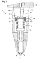
- FIG. 2 schematically shows a fuel injector 1 which is designed in the manner of a piezoelectrically operated injector.
- the illustration shows only a partial section of the fuel injector 1 below the intermediate piece 16.
- a corresponding pressurization or pressure relief of a nozzle needle control chamber 10 takes place, so that the nozzle needle 9, the required lifting movement for opening the fuel injection ports 3 for injection of the Fuel performs in the combustion chamber 4.
- the nozzle needle 9 is also received in a fuel injector 1 with a piezoelectric operation within a nozzle body 13, wherein for sealing the nozzle needle control chamber 10, a sealing sleeve 11 is provided.
- the nozzle sleeve 11 at the same time forms the magnetic yoke 6 of the measuring device 5.
- the electrical contacting is also carried out according to this embodiment via connecting lines 15, which are led out of the nozzle body 13.
- the change in the inductance of the magnetic circuit is based on the end face of the nozzle needle 9 adjacent to the nozzle needle control chamber 10, so that the diameter jump can be regarded as a jump to "zero diameter". In any case, the inductance changes during a lifting movement of the nozzle needle 9, so that the measuring device 5 can convert the opening end stop and the closing stop of the nozzle needle 9 into a corresponding electrical signal.
- the electrical measurement signal which is output by the measuring device 5 is shown in FIG.
- the respective abscissa represent the time, in the upper diagram, the ordinate represents the stroke of the valve piston, and the ordinate in the lower diagram outputs the measurement signal.
- VK the analogous movement of the valve piston and the nozzle needle
- the ordinate in the upper diagram is marked VK, which describes the valve piston.
- the ordinate in the lower diagram is denoted by a m, which indicates the measurement signal.
- the time that passes in the The time course of II to III shows the fully open phase of the valve piston and thus the nozzle needle, which follows from III to IV, the closing phase.
- I describes the start of opening, II the opening end, III the closing start and IV the closing end.
- the injection time runs.
- the measuring signal m between the beginning of opening I and the opening end II shows a signal increase, when reaching the opening end II, the signal abruptly drops to zero or by a damped periodic oscillatory motion to a zero Signal sets.
- the time of reaching the opening end II is very accurately detected. Analogous to the detection of the opening end II and the closing end IV can be detected.
- a change by means of the measuring signal m can be derived from the change in the periodic valve piston and / or nozzle needle movement, the change in the measuring signal m output by means of the measuring device being in the form of a discontinuity, the stroke end stop or closing times periodically following one another by means of the discontinuity and closing cycles are determined.
- the invention is not limited in its execution to the above-mentioned preferred embodiment. Rather, a number of variants is conceivable, which makes use of the illustrated solution even with fundamentally different types of use.
- the position of the measuring device 5 is not limited to the arrangements shown.
- the measuring device 5 can be arranged at any point along the entire movement device, wherein the movement device is not limited only to the valve piston 7 and the nozzle needle 9.
Landscapes
- Engineering & Computer Science (AREA)
- Chemical & Material Sciences (AREA)
- Combustion & Propulsion (AREA)
- Mechanical Engineering (AREA)
- General Engineering & Computer Science (AREA)
- Physics & Mathematics (AREA)
- Fluid Mechanics (AREA)
- Fuel-Injection Apparatus (AREA)
Abstract
Description
- Die vorliegende Erfindung betrifft einen Kraftstoffinjektor für eine Brennkraftmaschine nach dem Oberbegriff des Anspruchs 1. Insbesondere betrifft die Erfindung einen Kraftstoffinjektor mit einer Messeinrichtung zur Messung einer Öffnungs- und Schließbewegung einer Bewegungseinrichtung in einer Bewegungsachse.
- Kraftstoffinjektoren der hier interessierenden Art finden insbesondere Anwendung bei Brennkraftmaschinen, welche derartige Injektoren dafür nutzen, ein dosiertes Einspritzen des zu verbrennenden Kraftstoffs in eine Brennkraftmaschine zu ermöglichen.
- Brennkraftmaschinen können mit verschiedenartig ausgebildeten Kraftstoffinjektoren ausgeführt sein, wobei Kraftstoffinjektoren in solche unterschieden werden können, welche als magnetisch betriebene Injektoren bezeichnet werden und solche, welche als piezoelektrisch betriebene Injektoren zu bezeichnen sind. Magnetisch betriebene Injektoren umfassen einen Elektromagneten, welcher einen Anker bewegen kann, und die über eine Druckstange eine Magnetventilanordnung betätigen. Die Öffnungs- und Schließbewegung der Bewegungseinrichtung betrifft dabei einen Ventilkolben, dessen Hubbewegung in einer Bewegungsachse auf eine Düsennadel übertragen wird. Die Düsennadel öffnet und schließt den Kraftstofffluss durch kleine Einspritzbohrungen, welche am Düsenkörper des Kraftstoffinjektors angebracht sind und den Kraftstoff in einen Brennraum einspritzen.
- Piezoelektrisch betriebene Injektoren weisen hingegen einen Piezoaktor auf, um über eine nachgeschaltete Ventilanordnung die Öffnungs- und Schließbewegung der Düsennadel auszulösen. Die Bewegungseinrichtung bei piezoelektrisch betriebenen Injektoren kann sich daher auf die Öffnungs- und Schließbewegung der Düsennadel beschränken, wobei die Bewegungseinrichtung durch die dem Piezoaktor nachgeschaltete Ventilanordnung durch eine entsprechende Fluidbeaufschlagung eine Öffnungs- und Schließbewegung ausführt.
- Aus der Offenlegungsschrift
DE 199 37 559 A1 ist ein magnetisch betriebener Injektor bekannt, welcher für ein Einspritzsystem einer Brennkraftmaschine mit einem Magnetventil ausgeführt ist, das den Abfluss von Kraftstoff durch einen Abflusskanal aus einem Ventilsteuerraum steuert, wobei das Magnetventil Mittel zum Verschließen des Abflusskanals, einen von einen Elektromagneten betätigbaren und mit den Mitteln zum Verschließen des Abflusskanals in Wirkverbindung stehenden Anker sowie eine erste Ventilfeder und eine zweite Ventilfeder und einen ersten Hubendanschlag aufweist. Die erste Ventilfeder beaufschlagt den Anker mit einer größeren Federkraft in Schließrichtung, wobei von der Schließstellung des Magnetventils zum Erreichen des ersten Hubendanschlags die zweite Ventilfeder den Anker in Öffnungsrichtung mit einer kleineren Federkraft beaufschlagt. Dabei ist je eine Feder auf jeder Seite des Ankers angeordnet, um den Kraftstoffinjektor kompakt aufzubauen und ein verbessertes Betriebsverhalten bei verschiedenen Frequenzen zu erzielen. Jedoch bietet ein Kraftstoffinjektor der hierin offenbarten Art nicht die Möglichkeit, die Bewegung des Ankers zu messen, um mit den erfassten Messdaten eine mögliche Ansteuerung des Elektromagneten derart positiv zu beeinflussen, dass das Betriebsverhalten insbesondere hinsichtlich der eingespritzten Kraftstoffmenge und des genauen Zeitpunktes der Kraftstoffeinspritzung zu optimieren. - In der Offenlegungsschrift
DE 10 2004 015 744 A1 ist ein Kraftstoffinjektor nach Art eines piezoelektrisch betriebenen Injektors offenbart. Der Kraftstoffinjektor betrifft insbesondere einen Common- Rail- Injektor zum Einspritzen von Kraftstoff in einen Brennraum einer Brennkraftmaschine. Der Kraftstoffinjektor umfasst ein Injektorgehäuse, das einen Kraftstoffzulauf aufweist, der mit einer zentralen Kraftstoffhochdruckquelle außerhalb des Injektorgehäuses und mit einem Druckraum innerhalb des Injektorgehäuses in Verbindung steht, aus dem in Abhängigkeit von der Stellung eines Steuerventils mit Hochdruck beaufschlagter Kraftstoff eingespritzt wird. Dabei erfolgt eine Hubbewegung einer Düsennadel, welche innerhalb einer Führungsbohrung in einem Düsenkörper geführt ist. Die Düsennadel erreicht im Öffnungszeitpunkt einen Hubendanschlag, und kann ggf. von diesem abprallen bzw. eine Schwingbewegung auslösen. Gleichermaßen kann die Düsennadel auch im Schließzeitpunkt, in dem diese in der Spitze die Spritzlöcher zum Einspritzen des Kraftstoffs in den Brennraum verschließt, ein Schwingverhalten auslösen. Das Schwingverhalten wird immer genau dann eingeleitet, wenn die Düsennadel bzw. die Bewegungseinrichtung des Kraftstoffinjektors den Hubendanschlag bzw. den Schließsitz erreicht. Eine Kontrolle bzw. eine Rückkopplung des Öffnungs- und Schließverhaltens der Düsennadel zur Ansteuerung des Piezoaktors zur Auslösung der Öffnungs- und Schließbewegung der Düsennadel ist nicht möglich. Lediglich ein Ansteuern des Piezoaktors kann verändert werden, wobei eine Rückkopplung der Öffnungs- und Schließbewegung der Düsennadel nicht ausgewertet werden kann. - Lediglich zu Forschungs- und Entwicklungszwecken sind Messeinrichtungen zur Erfassung der Bewegung der Bewegungseinrichtungen innerhalb eines Kraftstoffinjektors bekannt, welche jedoch zur genauen Detektion des Zeitpunktes zur Erreichung des Hubendanschlags bzw. des Endanschlags im Schließsitz der Düsennadel bzw. der Bewegungseinrichtung ungeeignet sind. Diese Messeinrichtungen basieren auf einer kapazitiven Abstandsmessung, welche nicht geeignet ist, um größere Hubbewegungen einer Bewegungseinrichtung innerhalb eines Kraftstoffinjektors zu messen.
- Es ist daher die Aufgabe der vorliegenden Erfindung, einen Kraftstoffinjektor für eine Brennkraftmaschine zu schaffen, welcher eine Messeinrichtung zur Messung einer Öffnungs- und Schließbewegung einer Bewegungseinrichtung während des Betriebs des Kraftstoffinjektors umfasst.
- Diese Aufgabe wird ausgehend von einem Kraftstoffinjektor für eine Brennkraftmaschine gemäß dem Oberbegriff des Anspruchs 1 in Verbindung mit dessen kennzeichnenden Merkmalen gelöst. Vorteilhafte Weiterbildungen der Erfindung sind in den abhängigen Ansprüchen angegeben.
- Die Erfindung schließt die technische Lehre ein, dass die Messeinrichtung als ein Induktivsensor ausgebildet ist und einen Messkörper umfasst, der die Bewegungseinrichtung im Bereich einer in Bewegungsrichtung ausgebildeten Geometrieänderung wenigstens teilweise umschließt, um das Ende des Einspritzens des Kraftstoffes in den Brennraum und/oder den Endanschlag des Öffnungshubes zu erfassen.
- Die vorgeschlagene Ausführung eines Kraftstoffinjektors mit einer Messeinrichtung, welche nach dem Prinzip eines Induktivsensors arbeitet, bietet den Vorteil, dass die Bewegung der Bewegungseinrichtung in der Bewegungsachse über dem gesamten Hub der Bewegungseinrichtung erfasst werden kann, um sowohl das Ende des Einspritzens des Kraftstoffs in den Brennraum als auch den Endanschlag bzw. den Hubendanschlag im Öffnungshub zu erfassen. Die teilweise Umschließung der Bewegungseinrichtung durch den Messkörper erfolgt auf einem Teilstück der Länge der Bewegungseinrichtung in der Bewegungsachse. Ferner kann der Messkörper die Bewegungseinrichtung auf einem Vollkreis umschließen, wobei der Messkörper die Bewegungseinrichtung auch nur auf einem Teilkreis, d.h. auf einen Teilumfang der Bewegungseinrichtung umschließen kann. Die Messeinrichtung kann ein elektrisches Signal bereitstellen, aus dem das Ende des Einspritzen des Kraftstoffes in den Brennraum und/oder der Endanschlag des Öffnungshubes berechnet werden kann. Diese Informationen können beispielsweise dem Motorsteuergerät zugeführt werden, so dass der Kraftstoffinjektor über den Injektormagnet bzw. über den Injektor-Piezoaktor mit optimierten Steuersignalen betrieben werden kann.
- Gemäß einer weiteren Ausführungsform der vorliegenden Erfindung umfasst der Messkörper ein Magnetjoch, und der Kraftstoffinjektor ist als magnetisch betriebener Injektor ausgebildet, so dass gemäß der Bauweise eines magnetisch betriebenen Injektors die Bewegungseinrichtung durch einen Ventilkolben gebildet ist. Der Ventilkolben führt eine Axialbewegung in Richtung der Bewegungsachse aus, wobei die Axialbewegung mittels einer Fluidbeaufschlagung in den Ventilkolben eingeleitet wird, und lediglich die Steuerung der Fluidbeaufschlagung durch eine Ankerplatte erzeugt wird, die durch den Elektromagneten bewegt wird. Somit führt der Ventilkolben die gleiche Hubbewegung aus, wie die Düsennadel des Kraftstoffinjektors selbst auch. Wird durch die Messeinrichtung die Hubbewegung des Ventilkolbens detektiert, entsprechen die jeweiligen Endlagen für das Ende des Einspritzens des Kraftstoffs in den Brennraum bzw. den Endanschlag des Öffnungshubes des Ventilkolbens auch den Endlagen der Düsennadel. Damit ist der Ort der Anordnung der Messeinrichtung zwischen der Düsennadel und dem Steuerventil für die genaue Messung der Hubbewegung der Düsennadel letztlich nicht relevant.
- Vorteilhafterweise umfasst der Ventilkolben jedoch einen Durchmesserabsatz, welcher die Geometrieänderung in Bewegungsrichtung der Bewegungseinrichtung bildet. Die Geometrieänderung ist für das Messprinzip der Messeinrichtung als Induktivsensor wichtig, da erst die Änderung der magnetischen Induktivität eine Änderung eines Messsignals hervorruft. Die Änderung der magnetischen Induktivität kann also beispielsweise dadurch hervorgerufen werden, dass das Magnetjoch einen zylinderförmigen Eisenkern umfasst, der durch den Ventilkolben gebildet ist. Erfolgt nun eine Änderung des Durchmessers des Ventilkolbens, und bewegt sich die Änderung auf der Höhe des Magnetjochs, so ändert sich die magnetische Induktivität, was eine sehr präzise Messung ermöglicht, da sich die induzierte Spannung mit der Änderung der geometrisch bedingten Induktivität gleichermaßen ändert. Das Magnetjoch kann im Querschnitt U-förmig ausgebildet sein, wobei die Öffnung der U-Form in Richtung des Ventilkolbens zeigt. Somit bilden sich zwei Pole des Magnetjochs aus, welche den Ventilkolben ringförmig umschließen. Liegt beispielsweise der Durchmessersprung im Ventilkolben auf der Höhe eines Pols, so verändert sich die Induktivität des Magnetkreises in Abhängigkeit vom Hub des Ventilkolbens und damit vom Hub der Düsennadel.
- Gemäß einer weiteren Ausführungsform der Erfindung ist der Kraftstoffinjektor als piezoelektrisch betriebener Injektor mit einer fluidisch angesteuerten Düsennadel ausgebildet, so dass die Bewegungseinrichtung durch die Düsennadel selbst gebildet ist. Folglich muss der Messkörper in Form des Magnetjochs in Höhe der Düsennadel angeordnet sein, wobei die Düsennadel in einem Düsenkörper längsbeweglich aufgenommen ist, so dass gemäß einer möglichen Ausführungsform die Messeinrichtung im Düsenkörper selbst eingebaut ist, und das Magnetjoch die Düsennadel oder mit der Düsennadel bewegte Teile umschließt. Piezoelektrisch betriebene Injektoren weisen keinen Ventilkolben auf, der sich durch den Injektor selbst in länglicher Richtung erstreckt. Jedoch ist eine genaue Messung des Hubes der Düsennadel an bzw. mit der Düsennadel selbst mit der Messeinrichtung möglich.
- Vorteilhafterweise grenzt die Düsennadel an einen Düsennadelsteuerraum endseitig an, welcher mit einer Dichthülse abgedichtet ist, wobei die Messeinrichtung durch die Dichthülse und die in Bewegungsrichtung der Bewegungseinrichtung ausgebildete Geometrieänderung durch das an den Düsennadelsteuerraum angrenzende Ende der Düsennadel gebildet ist. Somit kann die Messeinrichtung und die Dichthülse zur Abdichtung des Düsennadelsteuerraums als einziges Konstruktionsbauteil ausgeführt sein. Als quasi - Durchmessersprung dient die Stirnseite der Düsennadel selbst, d.h. es erfolgt ein "Durchmessersprung auf Null".
- Um die Messeinrichtung ortsfest anzuordnen, wird diese entweder in dem Injektorkörper oder im Düsenkörper eingebaut. Der Injektorkörper und der Düsenkörper bilden jeweils den haltekörperfesten Teil des Injektors, wobei der Injektorkörper und der Düsenkörper selbst als magnetisches Material die Induktivität der Messeinrichtung beeinflussen. Zur Vermeidung von Wirbelströmen an den haltekörperfesten Teilen kann der das Feld führende haltekörperfeste Magnetkern radial geschlitzt sein, wobei der Haltekörper beispielsweise aus dem Injektorkörper oder dem Düsenkörper besteht. Alternativ besteht die Möglichkeit, dass dieser aus einem Material mit einem hohen spezifischen Widerstand ausgeführt ist. Derartige Materialien können ein Pulververbundmaterial, ein Ferritmaterial oder dergleichen betreffen. Die Messeinrichtung selbst umfasst einen Spulenkörper, welcher im Magnetjoch eingebettet ist. Der Spulenkörper kann entweder eine voneinander getrennte Erreger- und Sensorspule umfassen, wobei der Spulenkörper auch zugleich als Erreger- und Sensorspule ausgebildet sein kann.
- Gemäß einer weiteren Ausführungsform der Erfindung weist der Spulenkörper elektrische Anschlussleitungen auf, welche aus dem Aufnahmebereich der Messeinrichtung, also aus dem Injektorkörper oder aus dem Düsenkörper, herausgeführt werden müssen. Die Versiegelung der Anschlussleitungen in dem Körper, aus dem diese herausgeführt werden, kann nach Art einer Glaseinschmelzung ausgebildet sein. Somit findet die Glaseinschmelzung der elektrischen Anschlussleitungen aus dem Magnetjoch und/oder aus dem Injektorkörper und/oder aus dem Düsenkörper statt, wobei zugleich eine entsprechende Richtung erzielbar ist. Besonders vorteilhaft ist die Wahl von Kontaktstiften, die den gleichen Ausdehnungskoeffizienten wie das einschmelzende Glasmaterial hat, beispielsweise Molybdän.
- Die vorliegende Erfindung betrifft ferner ein Verfahren zur Erfassung des Endes des Einspritzens eines Kraftstoffs in einen Brennraum und/oder zur Erfassung des Endanschlags eines Öffnungshubes eines Ventilkolbens und/oder einer Düsennadel mit einer Messeinrichtung. Dabei wird die Messeinrichtung entweder mit einem konstanten elektrischen Strom oder mit einer konstanten elektrischen Spannung beschrieben. Wird die Spule der Messeinrichtung mit einem konstanten Strom beaufschlagt, so wird bei der Bewegung des Ventilkolbens bzw. der Düsennadel eine Spannung induziert, die in erster Näherung proportional zur Ventilkolbengeschwindigkeit ist. Wird hingegen die Spule mit einer konstanten Spannung betrieben, so ist im Wesentlichen eine Abweichung des Stroms von dessen Wert im Ruhezustand messbar, wobei die Abweichung Näherungsweise proportional zur Kolbengeschwindigkeit ist. Eine sehr schnelle Änderung der Ventilkolben- oder Düsennadelgeschwindigkeit hat quasi eine Unstetigkeit des Messsignals zur Folge, anhand derer der Hubendanschlags- oder Schließzeitpunkt detektiert werden kann. Diese Zeitpunkte können dann von einem Regler durch eine Variation des entsprechenden Ansteuerbeginns und des Ansteuerendes des Kraftstoffinjektors auf ihre Sollwerte eingeregelt werden. Dieser Regler kann beispielsweise Bestandteil eines Motorsteuergerätes sein oder mit diesem zumindest in Verbindung gebracht werden.
- Das vorliegende Verfahren erstreckt sich ferner darauf, dass sich aus einer Änderung der periodischen Ventilkolben- und/oder Düsennadelbewegung eine Änderung des mittels der Messeinrichtung ausgegebenen Messsignals in Form einer Unstetigkeit ergibt, und mittels der Unstetigkeit Hubendanschlags- oder Schließzeitpunkte periodisch aufeinander folgender Öffnungs- und Schließzyklen ermittelt werden.
- Weitere, die Erfindung verbessernde Maßnahmen werden nachstehend gemeinsam mit der Beschreibung bevorzugter Ausführungsbeispiele der Erfindung anhand von Figuren näher dargestellt.
- Es zeigt:
- Figur 1
- eine Ansicht eines Kraftstoffinjektors in einem Querschnitt, wobei der Kraftstoffinjektor als magnetisch betriebener Injektor ausgebildet ist, und die Messeinrichtung einen Ventilkolben innerhalb des Kraftstoffinjektors umschließt;
- Figur 2
- eine schematisierte Ansicht eines piezoelektrisch betriebenen Kraftstoffinjektors, wobei die Messeinrichtung einteilig mit der Dichthülse ausgeführt ist, welche einen endseitig an der Düsennadel angrenzenden Düsennadelsteuerraum abdichtet;
- Figur 3
- in einem Diagramm einen Verlauf einer Öffnungs- und Schließbewegung einer Düsennadel und ein zugehöriges Messsignal, welches durch die erfindungsgemäße Messeinrichtung ausgegeben wird.
- Die Figur 1 zeigt einen Ausschnitt eines Kraftstoffinjektors 1 in einer quergeschnittenen Darstellung. Dieser erstreckt sich in länglicher Richtung um eine Bewegungsachse 2, so dass die hubbeweglichen Bewegungseinrichtungen in der Bewegungsachse 2 bewegbar aufgenommen sind. Die hubbeweglichen Bewegungseinrichtungen zur Erzeugung einer Öffnungs- und Schließbewegung umfassen zunächst einen Ventilkolben 7, welcher längsbeweglich innerhalb des Injektorkörpers 12 aufgenommen ist. Der Ventilkolben 7 steht in Wirkverbindung mit der ebenfalls in der Bewegungsachse 2 längsbeweglich aufgenommenen Düsennadel 9, welche längsbeweglich innerhalb eines Düsenkörpers 13 geführt ist. Der Düsenkörper 13 ist angrenzend an den Injektorkörper 12 angeordnet, wobei sämtliche die Bewegungseinrichtung bildenden Komponenten wie der Ventilkolben 7 und die Düsennadel 9 innerhalb der gleichen Bewegungsachse 2 längsbeweglich geführt sind. Bei einer Hubbewegung der Düsennadel 9 werden innerhalb des Düsenkörpers 13 eingebrachte Kraftstoffeinspritzöffnungen 3 bei einer Hubbewegung kurzzeitig geöffnet und wieder verschlossen. Diese Hubbewegung wird von allen die Bewegungseinrichtung bildenden Komponenten ausgeführt. So ist etwa die Hubbewegung im Ventilkolben 7 analog zur Hubbewegung der Düsennadel 9.
- Konzentrisch um den Ventilkolben 7 erstreckt sich eine Messeinrichtung 5. Beispielhaft ist der Injektorkörper 12 geteilt dargestellt, um eine Montagemöglichkeit der Messeinrichtung 5 anzudeuten. Diese ist innerhalb des Injektorkörpers 12 aufgenommen, so dass die Messeinrichtung 5 keine Hubbewegung ausführt und gegenüber dem Ventilkolben 7 eine ruhende Position einnimmt. In der Höhe der Messeinrichtung 5 weist der Ventilkolben 7 einen Durchmesserabsatz 8 auf, so dass aufgrund der verschiedenen Durchmesser des Ventilkolbens 7 der Magnetkreis in Abhängigkeit von der Längsposition des Ventilkolbens 7 in Richtung der Bewegungsachse 2 seine Induktivität ändert. Die Messeinrichtung 5 besteht im Wesentlichen aus einem Magnetjoch 6, welches ringförmig ausgebildet ist und einen U-förmigen Querschnitt aufweist. Die Öffnung der U-Form weist dabei nach innen in Richtung des Ventilkolbens 7, wobei der Durchmesserabsatz 8 an zumindest einen Ende des Magnetjochs 6 angrenzt, um eine maximale Änderung der Induktivität hervorzurufen. Innerhalb des Magnetjochs 6 ist ein Spulenkörper 14 aufgenommen, welcher über eine Anschlussleitung 15 extern kontaktierbar ist. Führt nunmehr der Ventilkolben 7 eine Hubbewegung entlang der Bewegungsachse 2 aus, welche durch einen - nicht näher dargestellten - Elektromagneten eingeleitet wird, so öffnet die Düsennadel 9 die Kraftstoffeinspritzöffnungen 3, so dass Kraftstoff in den Brennraum 4 eingespritzt werden kann. Die Hubbewegung bewirkt gleichermaßen eine Ortsänderung des Durchmesserabsatzes 8 relativ zum Magnetjoch 6, so dass sich die Induktivität des Magnetkreises ändert. Diese Änderung wird über eine Auswerteeinheit analysiert und gibt eine direkte Information über die Hubbewegung der Bewegungseinrichtung.
- In Figur 2 ist schematisch ein Kraftstoffinjektor 1 gezeigt, welcher nach Art eines piezoelektrisch betriebenen Injektors ausgeführt ist. Die Darstellung zeigt lediglich einen Teilschnitt des Kraftstoffinjektors 1 unterhalb des Zwischenstückes 16. Über die Verbindungskanäle 17, 18 und 19 findet eine entsprechende Druckbeaufschlagung bzw. Druckentlastung eines Düsennadelsteuerraums 10 statt, so dass die Düsennadel 9 die erforderliche Hubbewegung zur Öffnung der Kraftstoffeinspritzöffnungen 3 zur Einspritzung des Kraftstoffs in den Brennraum 4 ausführt. Die Düsennadel 9 ist auch bei einem Kraftstoffinjektor 1 mit einem piezoelektrischen Betrieb innerhalb eines Düsenkörpers 13 aufgenommen, wobei zur Abdichtung des Düsennadelsteuerraums 10 eine Dichthülse 11 vorgesehen ist. Gemäß der vorliegenden Erfindung bildet die Düsenhülse 11 zugleich das Magnetjoch 6 der Messeinrichtung 5. Dargestellt ist die Dichthülse 11 in einer Ringform, welche außenseitig den Spulenkörper 14 aufnimmt. Die elektrische Kontaktierung erfolgt auch gemäß dieses Ausführungsbeispiels über Anschlussleitungen 15, welche aus dem Düsenkörper 13 herausgeführt sind. Die Änderung der Induktivität des Magnetkreises basiert auf der Endfläche der Düsennadel 9 angrenzend an den Düsennadelsteuerraum 10, so dass der Durchmessersprung als ein Sprung auf "Durchmesser Null" betrachtet werden kann. Jedenfalls ändert sich die Induktivität bei einer Hubbewegung der Düsennadel 9, so dass die Messeinrichtung 5 den Öffnungsendanschlag sowie den Schließanschlag der Düsennadel 9 in ein entsprechendes elektrisches Signal umwandeln kann.
- Das elektrische Messsignal, welches durch die Messeinrichtung 5 ausgegeben wird, ist in Figur 3 dargestellt. Die jeweiligen Abszissen stellen die Zeit dar, wobei im oberen Diagramm die Ordinate den Hub des Ventilkolbens darstellt, und die Ordinate im unteren Diagramm das Messsignal ausgibt. Mit der analogen Bewegung des Ventilkolbens und der Düsennadel ist die Ordinate im oberen Diagramm mit VK gekennzeichnet, was den Ventilkolben beschreibt. Die Ordinate im unteren Diagramm ist mit einem m bezeichnet, welches das Messsignal andeutet. Öffnet der Kraftstoffinjektor durch eine Hubbewegung des Ventilkolbens, so verläuft die Kurve, welche im oberen Diagramm die Bewegung des Ventilkolbens darstellt, von der Position I zur Position II. Die Zeit, welche vergeht, in der sich der Ventilkolben von I bis II bewegt, stellt die Öffnungsphase dar. Der Zeitverlauf von II bis III zeigt die vollständig geöffnete Phase des Ventilkolbens und damit der Düsennadel, wonach von III bis IV die Schließphase folgt. Damit beschreibt I den Öffnungsbeginn, II das Öffnungsende, III den Schließbeginn und IV das Schließende. Zwischen dem Öffnungsbeginn I und dem Schließende IV verläuft die Einspritzzeit. Gemäß dem Verlauf der Öffnungs- und Schließbewegung des Ventilkolbens VK zeigt das Messsignal m zwischen dem Öffnungsbeginn I und dem Öffnungsende II einen Signalanstieg, wobei bei Erreichen des Öffnungsendes II das Signal schlagartig auf Null abfällt bzw. sich durch eine gedämpfte periodische Schwingbewegung auf ein Null-Signal einstellt. Damit ist der Zeitpunkt des Erreichens des Öffnungsendes II sehr exakt detektierbar. Analog zur Detektion des Öffnungsendes II kann auch das Schließende IV detektiert werden. Aus der Änderung der periodischen Ventilkolben- und/oder Düsennadelbewegung ist eine Änderung mittels des Messsignals m ableitbar, wobei sich die Änderung des mittels der Messeinrichtung ausgegebenen Messsignals m in Form einer Unstetigkeit ergibt, wobei mittels der Unstetigkeit die Hubendanschlags- oder Schließzeitpunkte periodisch aufeinander folgender Öffnungs- und Schließzyklen ermittelt werden.
- Die Erfindung beschränkt sich in ihrer Ausführung nicht auf das vorstehend angegebene bevorzugte Ausführungsbeispiel. Vielmehr ist eine Anzahl von Varianten denkbar, welche von der dargestellten Lösung auch bei grundsätzlich anders gearteten Ausführungen Gebrauch macht. Insbesondere sei angemerkt, dass die Position der Messeinrichtung 5 nicht auf die dargestellten Anordnungen begrenzt ist. Die Messeinrichtung 5 kann an einer beliebigen Stelle entlang der gesamten Bewegungsseinrichtung angeordnet werden, wobei die Bewegungseinrichtung nicht lediglich auf den Ventilkolben 7 sowie die Düsennadel 9 begrenzt ist.
Claims (10)
- Kraftstoffinjektor (1) für eine Brennkraftmaschine mit einer Bewegungseinrichtung, welche eine Öffnungs- und Schließbewegung in einer Bewegungsachse (2) zur Öffnung und Schließung wenigstens einer Kraftstoffeinspritzöffnung (3) zur Einspritzung von Kraftstoff in einen Brennraum (4) ausführt, wobei der Kraftstoffinjektor (1) eine Messeinrichtung (5) aufweist,
dadurch gekennzeichnet, dass die Messeinrichtung (5) als ein Induktivsensor ausgebildet ist und einen Messkörper umfasst, der die Bewegungseinrichtung im Bereich einer in Bewegungsrichtung ausgebildeten Geometrieänderung wenigstens teilweise umschließt, um das Ende des Einspritzens in den Brennraum und/oder den Endanschlag des Öffnungshubes zu erfassen. - Kraftstoffinjektor (1) nach Anspruch 1,
dadurch gekennzeichnet, dass der Messkörper ein Magnetjoch (6) umfasst und der Kraftstoffinjektor (1) als magnetisch betriebener Injektor ausgebildet ist und die Bewegungseinrichtung durch einen Ventilkolben (7) gebildet ist. - Kraftstoffinjektor (1) nach Anspruch 2,
dadurch gekennzeichnet, dass der Ventilkolben (7) einen Durchmesserabsatz (8) umfasst, welcher die Geometrieänderung in Bewegungsrichtung der Bewegungseinrichtung bildet. - Kraftstoffinjektor (1) nach Anspruch 1,
dadurch gekennzeichnet, dass der Kraftstoffinjektor (1) als piezoelektrisch betriebener Injektor mit einer fluidisch angesteuerten Düsennadel (9) ausgebildet ist, und die Bewegungseinrichtung die Düsennadel (9) ist. - Kraftstoffinjektor (1) nach Anspruch 4,
dadurch gekennzeichnet, dass die Düsennadel (9) an einen Düsennadelsteuerraum (10) endseitig angrenzt, welcher mit einer Dichthülse (11) abgedichtet ist, wobei die Messeinrichtung (5) durch die Dichthülse (11) und die in Bewegungsrichtung der Bewegungseinrichtung ausgebildete Geometrieänderung durch das an den Düsennadelsteuerraum (10) angrenzende Ende der Düsennadel (9) gebildet ist. - Kraftstoffinjektor (1) nach einem der vorgenannten Ansprüche,
dadurch gekennzeichnet, dass der Kraftstoffinjektor (1) einen Injektorkörper (12) und einen an diesem angeordneten Düsenkörper (13) umfasst, und die Messeinrichtung (5) im Injektorkörper (12) und/oder im Düsenkörper (13) aufgenommen ist. - Kraftstoffinjektor (1) nach einem der vorgenannten Ansprüche,
dadurch gekennzeichnet, dass die Messeinrichtung (5) einen im Magnetjoch (6) eingebetteten Spulenkörper (14) umfasst, welcher als Erreger- und Sensorspule ausgebildet ist, wobei das Magnetjoch (6) radial geschlitzt ist und/oder ein Material mit einem hohen spezifischen Widerstand, umfassen ein Pulververbundmaterial und/oder ein Ferritmaterial, aufweist. - Kraftstoffinjektor (1) nach Anspruch 7,
dadurch gekennzeichnet, dass der Spulenkörper (14) elektrische Anschlussleitungen (15) aufweist, welche nach Art einer Glaseinschmelzung aus dem Magnetjoch (6) und/oder aus dem Injektorkörper (12) und/oder aus dem Düsenkörper (13) herausgeführt und abgedichtet sind. - Verfahren zur Erfassung des Endes des Einspritzens eines Kraftstoffes in einen Brennraum und/oder zur Erfassung des Endanschlags eines Öffnungshubes eines Ventilkolbens (7) und/oder einer Düsennadel (9) mit einer Messeinrichtung (5) nach einem der Ansprüche 1 bis 8,
dadurch gekennzeichnet, dass die Messeinrichtung (5) mit einem konstanten elektrischen Strom oder mit einer konstanten elektrischen Spannung betrieben wird. - Verfahren nach Anspruch 9,
dadurch gekennzeichnet, dass sich aus einer Änderung der periodischen Ventilkolben - und/oder Düsennadelbewegung eine Änderung des mittels der Messeinrichtung (5) ausgegebenen Messsignals in Form einer Unstetigkeit ergibt, und mittels der Unstetigkeit Hubendanschlags- oder Schließzeitpunkte periodisch aufeinander folgender Öffnungs- und Schließzyklen ermittelt werden.
Applications Claiming Priority (1)
| Application Number | Priority Date | Filing Date | Title |
|---|---|---|---|
| DE102006051205A DE102006051205A1 (de) | 2006-10-30 | 2006-10-30 | Kraftstoffinjektor mit einer Messeinrichtung |
Publications (2)
| Publication Number | Publication Date |
|---|---|
| EP1925813A1 true EP1925813A1 (de) | 2008-05-28 |
| EP1925813B1 EP1925813B1 (de) | 2009-11-18 |
Family
ID=39185930
Family Applications (1)
| Application Number | Title | Priority Date | Filing Date |
|---|---|---|---|
| EP07115363A Not-in-force EP1925813B1 (de) | 2006-10-30 | 2007-08-31 | Kraftstoffinjektor mit einer Messeinrichtung |
Country Status (3)
| Country | Link |
|---|---|
| EP (1) | EP1925813B1 (de) |
| AT (1) | ATE449252T1 (de) |
| DE (2) | DE102006051205A1 (de) |
Cited By (2)
| Publication number | Priority date | Publication date | Assignee | Title |
|---|---|---|---|---|
| GB2497515A (en) * | 2011-12-05 | 2013-06-19 | Gm Global Tech Operations Inc | Solenoid fuel injector system with needle position feedback |
| GB2549747A (en) * | 2016-04-27 | 2017-11-01 | Delphi Int Operations Luxembourg Sarl | Fuel injector |
Families Citing this family (1)
| Publication number | Priority date | Publication date | Assignee | Title |
|---|---|---|---|---|
| ITRM20120507A1 (it) | 2012-10-19 | 2014-04-20 | Politecnico Di Bari | Sistema ottico per la misurazione dello spostamento di un corpo mobile annegato in un fluido |
Citations (6)
| Publication number | Priority date | Publication date | Assignee | Title |
|---|---|---|---|---|
| DE3137761A1 (de) | 1981-09-23 | 1983-03-31 | Robert Bosch Gmbh, 7000 Stuttgart | Kraftstoff-einspritzduese fuer brennkraftmaschinen |
| EP0427947A1 (de) * | 1989-11-14 | 1991-05-22 | Robert Bosch Gmbh | Kraftstoffeinspritzdüse für Brennkraftmaschinen |
| GB2262809A (en) * | 1991-12-24 | 1993-06-30 | Bosch Gmbh Robert | Measuring the mechanical movement of a solenoid valve armature |
| GB2280712A (en) * | 1993-08-02 | 1995-02-08 | Daimler Benz Ag | High pressure fuel injection system |
| GB2340610A (en) * | 1998-08-18 | 2000-02-23 | Lucas Ind Plc | Needle lift sensor |
| DE102004015744A1 (de) | 2004-03-31 | 2005-10-13 | Robert Bosch Gmbh | Common-Rail-Injektor |
-
2006
- 2006-10-30 DE DE102006051205A patent/DE102006051205A1/de not_active Withdrawn
-
2007
- 2007-08-31 EP EP07115363A patent/EP1925813B1/de not_active Not-in-force
- 2007-08-31 DE DE502007002021T patent/DE502007002021D1/de active Active
- 2007-08-31 AT AT07115363T patent/ATE449252T1/de active
Patent Citations (6)
| Publication number | Priority date | Publication date | Assignee | Title |
|---|---|---|---|---|
| DE3137761A1 (de) | 1981-09-23 | 1983-03-31 | Robert Bosch Gmbh, 7000 Stuttgart | Kraftstoff-einspritzduese fuer brennkraftmaschinen |
| EP0427947A1 (de) * | 1989-11-14 | 1991-05-22 | Robert Bosch Gmbh | Kraftstoffeinspritzdüse für Brennkraftmaschinen |
| GB2262809A (en) * | 1991-12-24 | 1993-06-30 | Bosch Gmbh Robert | Measuring the mechanical movement of a solenoid valve armature |
| GB2280712A (en) * | 1993-08-02 | 1995-02-08 | Daimler Benz Ag | High pressure fuel injection system |
| GB2340610A (en) * | 1998-08-18 | 2000-02-23 | Lucas Ind Plc | Needle lift sensor |
| DE102004015744A1 (de) | 2004-03-31 | 2005-10-13 | Robert Bosch Gmbh | Common-Rail-Injektor |
Cited By (3)
| Publication number | Priority date | Publication date | Assignee | Title |
|---|---|---|---|---|
| GB2497515A (en) * | 2011-12-05 | 2013-06-19 | Gm Global Tech Operations Inc | Solenoid fuel injector system with needle position feedback |
| GB2549747A (en) * | 2016-04-27 | 2017-11-01 | Delphi Int Operations Luxembourg Sarl | Fuel injector |
| WO2017186691A1 (en) * | 2016-04-27 | 2017-11-02 | Delphi International Operations Luxembourg S.À R.L. | Fuel injector |
Also Published As
| Publication number | Publication date |
|---|---|
| ATE449252T1 (de) | 2009-12-15 |
| DE102006051205A1 (de) | 2008-05-08 |
| DE502007002021D1 (de) | 2009-12-31 |
| EP1925813B1 (de) | 2009-11-18 |
Similar Documents
| Publication | Publication Date | Title |
|---|---|---|
| EP2478200B1 (de) | Verfahren und vorrichtung zum bestimmen einer bewegung eines nadels eines einspritzventils | |
| EP1925814A1 (de) | Kraftstoffinjektor mit einer Messeinrichtung | |
| EP2640955B1 (de) | Kraftstoffinjektor | |
| DE10122353B4 (de) | Brennstoffeinspritzventil | |
| DE102010000827A1 (de) | Kraftstoffinjektor | |
| DE3302294A1 (de) | Kraftstoffeinspritzvorrichtung fuer luftverdichtende, selbstzuendende brennkraftmaschinen | |
| DE3633107A1 (de) | Kraftstoffeinspritzvorrichtung fuer brennkraftmaschinen | |
| WO1998036160A1 (de) | Ventileinrichtung eines verbrennungsmotors | |
| EP1925813B1 (de) | Kraftstoffinjektor mit einer Messeinrichtung | |
| DE10142302A1 (de) | Brennstoffeinspritzventil | |
| EP1095215B1 (de) | Brennstoffeinspritzventil | |
| WO2005042969A1 (de) | Sensoranordnung zur erfassung der bewegung eines durch einen aktuator hin und her bewegten stellgliedes | |
| DE10154383A1 (de) | Hochdruckeinspritzeinrichtung mit berührungsloser Stellwegsensoranordnung für den Ventilkörper | |
| DE102012206586A1 (de) | Verfahren zum Betreiben eines Kraftstoffinjektors | |
| DE10315815A1 (de) | Verfahren zur Ermittlung der individuellen Ansteuerspannung eines piezoelektrischen Elements | |
| DE10345967B4 (de) | Brennstoffeinspritzventil | |
| DE102019210614A1 (de) | Ventil zum Zumessen eines Fluids und Brennstoffeinspritzanlage | |
| EP2496824B1 (de) | Steuerventilanordnung | |
| WO2010081582A1 (de) | Vorrichtung zur einspritzung von kraftstoff | |
| DE102004015045B4 (de) | Verfahren zur Ermittlung der Position eines beweglichen Verschlusselementes eines Einspritzventils | |
| EP2357353B1 (de) | Verfahren zur Erkennung des Schließzeitpunktes eines Einspritzventilgliedes in einem Kraftstoffeinspritzventil sowie Kraftstoffeinspritzventil | |
| EP1651928B1 (de) | Messvorrichtung und verfahren zur erfassung der position eines elektrisch leitfähigen messobjekts | |
| DE19735232A1 (de) | Verfahren zur Dämpfung eines Brennstoffeinspritzventiles und Brennstoffeinspritzventil | |
| DE10064511C2 (de) | Vorrichtung, Verfahren und Computerprogramm zum Messen der Einspritzmenge von Einspritzsystemen, insbesondere für Brennkraftmaschinen von Kraftfahrzeugen | |
| DE3302292A1 (de) | Elektromagnetisch betaetigbares steuerventil fuer kraftstoffeinspritzvorrichtungen |
Legal Events
| Date | Code | Title | Description |
|---|---|---|---|
| PUAI | Public reference made under article 153(3) epc to a published international application that has entered the european phase |
Free format text: ORIGINAL CODE: 0009012 |
|
| AK | Designated contracting states |
Kind code of ref document: A1 Designated state(s): AT BE BG CH CY CZ DE DK EE ES FI FR GB GR HU IE IS IT LI LT LU LV MC MT NL PL PT RO SE SI SK TR |
|
| AX | Request for extension of the european patent |
Extension state: AL BA HR MK RS |
|
| 17P | Request for examination filed |
Effective date: 20081128 |
|
| 17Q | First examination report despatched |
Effective date: 20081230 |
|
| AKX | Designation fees paid |
Designated state(s): AT BE BG CH CY CZ DE DK EE ES FI FR GB GR HU IE IS IT LI LT LU LV MC MT NL PL PT RO SE SI SK TR |
|
| GRAP | Despatch of communication of intention to grant a patent |
Free format text: ORIGINAL CODE: EPIDOSNIGR1 |
|
| GRAS | Grant fee paid |
Free format text: ORIGINAL CODE: EPIDOSNIGR3 |
|
| GRAA | (expected) grant |
Free format text: ORIGINAL CODE: 0009210 |
|
| AK | Designated contracting states |
Kind code of ref document: B1 Designated state(s): AT BE BG CH CY CZ DE DK EE ES FI FR GB GR HU IE IS IT LI LT LU LV MC MT NL PL PT RO SE SI SK TR |
|
| REG | Reference to a national code |
Ref country code: GB Ref legal event code: FG4D Free format text: NOT ENGLISH |
|
| REG | Reference to a national code |
Ref country code: CH Ref legal event code: EP |
|
| REG | Reference to a national code |
Ref country code: IE Ref legal event code: FG4D |
|
| REF | Corresponds to: |
Ref document number: 502007002021 Country of ref document: DE Date of ref document: 20091231 Kind code of ref document: P |
|
| REG | Reference to a national code |
Ref country code: NL Ref legal event code: VDEP Effective date: 20091118 |
|
| LTIE | Lt: invalidation of european patent or patent extension |
Effective date: 20091118 |
|
| PG25 | Lapsed in a contracting state [announced via postgrant information from national office to epo] |
Ref country code: SE Free format text: LAPSE BECAUSE OF FAILURE TO SUBMIT A TRANSLATION OF THE DESCRIPTION OR TO PAY THE FEE WITHIN THE PRESCRIBED TIME-LIMIT Effective date: 20091118 Ref country code: PT Free format text: LAPSE BECAUSE OF FAILURE TO SUBMIT A TRANSLATION OF THE DESCRIPTION OR TO PAY THE FEE WITHIN THE PRESCRIBED TIME-LIMIT Effective date: 20100318 Ref country code: LT Free format text: LAPSE BECAUSE OF FAILURE TO SUBMIT A TRANSLATION OF THE DESCRIPTION OR TO PAY THE FEE WITHIN THE PRESCRIBED TIME-LIMIT Effective date: 20091118 Ref country code: ES Free format text: LAPSE BECAUSE OF FAILURE TO SUBMIT A TRANSLATION OF THE DESCRIPTION OR TO PAY THE FEE WITHIN THE PRESCRIBED TIME-LIMIT Effective date: 20100228 Ref country code: FI Free format text: LAPSE BECAUSE OF FAILURE TO SUBMIT A TRANSLATION OF THE DESCRIPTION OR TO PAY THE FEE WITHIN THE PRESCRIBED TIME-LIMIT Effective date: 20091118 Ref country code: IS Free format text: LAPSE BECAUSE OF FAILURE TO SUBMIT A TRANSLATION OF THE DESCRIPTION OR TO PAY THE FEE WITHIN THE PRESCRIBED TIME-LIMIT Effective date: 20100318 |
|
| PG25 | Lapsed in a contracting state [announced via postgrant information from national office to epo] |
Ref country code: CY Free format text: LAPSE BECAUSE OF FAILURE TO SUBMIT A TRANSLATION OF THE DESCRIPTION OR TO PAY THE FEE WITHIN THE PRESCRIBED TIME-LIMIT Effective date: 20091118 Ref country code: PL Free format text: LAPSE BECAUSE OF FAILURE TO SUBMIT A TRANSLATION OF THE DESCRIPTION OR TO PAY THE FEE WITHIN THE PRESCRIBED TIME-LIMIT Effective date: 20091118 Ref country code: SI Free format text: LAPSE BECAUSE OF FAILURE TO SUBMIT A TRANSLATION OF THE DESCRIPTION OR TO PAY THE FEE WITHIN THE PRESCRIBED TIME-LIMIT Effective date: 20091118 Ref country code: LV Free format text: LAPSE BECAUSE OF FAILURE TO SUBMIT A TRANSLATION OF THE DESCRIPTION OR TO PAY THE FEE WITHIN THE PRESCRIBED TIME-LIMIT Effective date: 20091118 |
|
| REG | Reference to a national code |
Ref country code: IE Ref legal event code: FD4D |
|
| PG25 | Lapsed in a contracting state [announced via postgrant information from national office to epo] |
Ref country code: DK Free format text: LAPSE BECAUSE OF FAILURE TO SUBMIT A TRANSLATION OF THE DESCRIPTION OR TO PAY THE FEE WITHIN THE PRESCRIBED TIME-LIMIT Effective date: 20091118 Ref country code: EE Free format text: LAPSE BECAUSE OF FAILURE TO SUBMIT A TRANSLATION OF THE DESCRIPTION OR TO PAY THE FEE WITHIN THE PRESCRIBED TIME-LIMIT Effective date: 20091118 Ref country code: BG Free format text: LAPSE BECAUSE OF FAILURE TO SUBMIT A TRANSLATION OF THE DESCRIPTION OR TO PAY THE FEE WITHIN THE PRESCRIBED TIME-LIMIT Effective date: 20100218 Ref country code: NL Free format text: LAPSE BECAUSE OF FAILURE TO SUBMIT A TRANSLATION OF THE DESCRIPTION OR TO PAY THE FEE WITHIN THE PRESCRIBED TIME-LIMIT Effective date: 20091118 Ref country code: IE Free format text: LAPSE BECAUSE OF FAILURE TO SUBMIT A TRANSLATION OF THE DESCRIPTION OR TO PAY THE FEE WITHIN THE PRESCRIBED TIME-LIMIT Effective date: 20091118 Ref country code: RO Free format text: LAPSE BECAUSE OF FAILURE TO SUBMIT A TRANSLATION OF THE DESCRIPTION OR TO PAY THE FEE WITHIN THE PRESCRIBED TIME-LIMIT Effective date: 20091118 |
|
| PG25 | Lapsed in a contracting state [announced via postgrant information from national office to epo] |
Ref country code: CZ Free format text: LAPSE BECAUSE OF FAILURE TO SUBMIT A TRANSLATION OF THE DESCRIPTION OR TO PAY THE FEE WITHIN THE PRESCRIBED TIME-LIMIT Effective date: 20091118 Ref country code: SK Free format text: LAPSE BECAUSE OF FAILURE TO SUBMIT A TRANSLATION OF THE DESCRIPTION OR TO PAY THE FEE WITHIN THE PRESCRIBED TIME-LIMIT Effective date: 20091118 |
|
| PLBE | No opposition filed within time limit |
Free format text: ORIGINAL CODE: 0009261 |
|
| STAA | Information on the status of an ep patent application or granted ep patent |
Free format text: STATUS: NO OPPOSITION FILED WITHIN TIME LIMIT |
|
| 26N | No opposition filed |
Effective date: 20100819 |
|
| PG25 | Lapsed in a contracting state [announced via postgrant information from national office to epo] |
Ref country code: GR Free format text: LAPSE BECAUSE OF FAILURE TO SUBMIT A TRANSLATION OF THE DESCRIPTION OR TO PAY THE FEE WITHIN THE PRESCRIBED TIME-LIMIT Effective date: 20100219 |
|
| BERE | Be: lapsed |
Owner name: ROBERT BOSCH G.M.B.H. Effective date: 20100831 |
|
| PG25 | Lapsed in a contracting state [announced via postgrant information from national office to epo] |
Ref country code: MC Free format text: LAPSE BECAUSE OF NON-PAYMENT OF DUE FEES Effective date: 20100831 Ref country code: IT Free format text: LAPSE BECAUSE OF FAILURE TO SUBMIT A TRANSLATION OF THE DESCRIPTION OR TO PAY THE FEE WITHIN THE PRESCRIBED TIME-LIMIT Effective date: 20091118 |
|
| PG25 | Lapsed in a contracting state [announced via postgrant information from national office to epo] |
Ref country code: BE Free format text: LAPSE BECAUSE OF NON-PAYMENT OF DUE FEES Effective date: 20100831 |
|
| PG25 | Lapsed in a contracting state [announced via postgrant information from national office to epo] |
Ref country code: MT Free format text: LAPSE BECAUSE OF FAILURE TO SUBMIT A TRANSLATION OF THE DESCRIPTION OR TO PAY THE FEE WITHIN THE PRESCRIBED TIME-LIMIT Effective date: 20091118 |
|
| REG | Reference to a national code |
Ref country code: CH Ref legal event code: PL |
|
| GBPC | Gb: european patent ceased through non-payment of renewal fee |
Effective date: 20110831 |
|
| PG25 | Lapsed in a contracting state [announced via postgrant information from national office to epo] |
Ref country code: LI Free format text: LAPSE BECAUSE OF NON-PAYMENT OF DUE FEES Effective date: 20110831 Ref country code: CH Free format text: LAPSE BECAUSE OF NON-PAYMENT OF DUE FEES Effective date: 20110831 |
|
| PG25 | Lapsed in a contracting state [announced via postgrant information from national office to epo] |
Ref country code: GB Free format text: LAPSE BECAUSE OF NON-PAYMENT OF DUE FEES Effective date: 20110831 |
|
| PG25 | Lapsed in a contracting state [announced via postgrant information from national office to epo] |
Ref country code: LU Free format text: LAPSE BECAUSE OF NON-PAYMENT OF DUE FEES Effective date: 20100831 Ref country code: HU Free format text: LAPSE BECAUSE OF FAILURE TO SUBMIT A TRANSLATION OF THE DESCRIPTION OR TO PAY THE FEE WITHIN THE PRESCRIBED TIME-LIMIT Effective date: 20100519 |
|
| PG25 | Lapsed in a contracting state [announced via postgrant information from national office to epo] |
Ref country code: TR Free format text: LAPSE BECAUSE OF FAILURE TO SUBMIT A TRANSLATION OF THE DESCRIPTION OR TO PAY THE FEE WITHIN THE PRESCRIBED TIME-LIMIT Effective date: 20091118 |
|
| REG | Reference to a national code |
Ref country code: AT Ref legal event code: MM01 Ref document number: 449252 Country of ref document: AT Kind code of ref document: T Effective date: 20120831 |
|
| PG25 | Lapsed in a contracting state [announced via postgrant information from national office to epo] |
Ref country code: AT Free format text: LAPSE BECAUSE OF NON-PAYMENT OF DUE FEES Effective date: 20120831 |
|
| REG | Reference to a national code |
Ref country code: FR Ref legal event code: PLFP Year of fee payment: 10 |
|
| REG | Reference to a national code |
Ref country code: FR Ref legal event code: PLFP Year of fee payment: 11 |
|
| REG | Reference to a national code |
Ref country code: FR Ref legal event code: PLFP Year of fee payment: 12 |
|
| PGFP | Annual fee paid to national office [announced via postgrant information from national office to epo] |
Ref country code: FR Payment date: 20190822 Year of fee payment: 13 |
|
| PGFP | Annual fee paid to national office [announced via postgrant information from national office to epo] |
Ref country code: DE Payment date: 20191021 Year of fee payment: 13 |
|
| REG | Reference to a national code |
Ref country code: DE Ref legal event code: R119 Ref document number: 502007002021 Country of ref document: DE |
|
| PG25 | Lapsed in a contracting state [announced via postgrant information from national office to epo] |
Ref country code: DE Free format text: LAPSE BECAUSE OF NON-PAYMENT OF DUE FEES Effective date: 20210302 Ref country code: FR Free format text: LAPSE BECAUSE OF NON-PAYMENT OF DUE FEES Effective date: 20200831 |