EP1925807A2 - Gasturbinenmotor eines Turbolüfters mit Gondelanordnung - Google Patents
Gasturbinenmotor eines Turbolüfters mit Gondelanordnung Download PDFInfo
- Publication number
- EP1925807A2 EP1925807A2 EP07254232A EP07254232A EP1925807A2 EP 1925807 A2 EP1925807 A2 EP 1925807A2 EP 07254232 A EP07254232 A EP 07254232A EP 07254232 A EP07254232 A EP 07254232A EP 1925807 A2 EP1925807 A2 EP 1925807A2
- Authority
- EP
- European Patent Office
- Prior art keywords
- nacelle
- outlet
- arrangement
- engine
- jet
- Prior art date
- Legal status (The legal status is an assumption and is not a legal conclusion. Google has not performed a legal analysis and makes no representation as to the accuracy of the status listed.)
- Withdrawn
Links
- 230000003247 decreasing effect Effects 0.000 claims description 6
- 230000003068 static effect Effects 0.000 claims description 6
- 230000003321 amplification Effects 0.000 claims description 4
- 238000000034 method Methods 0.000 claims description 4
- 238000003199 nucleic acid amplification method Methods 0.000 claims description 4
- 238000004891 communication Methods 0.000 claims description 3
- 239000012530 fluid Substances 0.000 claims description 3
- 230000007423 decrease Effects 0.000 abstract description 2
- 239000003570 air Substances 0.000 description 22
- 239000007789 gas Substances 0.000 description 10
- 239000012080 ambient air Substances 0.000 description 3
- 230000000694 effects Effects 0.000 description 3
- 239000000567 combustion gas Substances 0.000 description 2
- 238000012986 modification Methods 0.000 description 2
- 230000004048 modification Effects 0.000 description 2
- 239000000446 fuel Substances 0.000 description 1
- 230000005855 radiation Effects 0.000 description 1
Images


Classifications
-
- F—MECHANICAL ENGINEERING; LIGHTING; HEATING; WEAPONS; BLASTING
- F02—COMBUSTION ENGINES; HOT-GAS OR COMBUSTION-PRODUCT ENGINE PLANTS
- F02K—JET-PROPULSION PLANTS
- F02K3/00—Plants including a gas turbine driving a compressor or a ducted fan
- F02K3/02—Plants including a gas turbine driving a compressor or a ducted fan in which part of the working fluid by-passes the turbine and combustion chamber
- F02K3/04—Plants including a gas turbine driving a compressor or a ducted fan in which part of the working fluid by-passes the turbine and combustion chamber the plant including ducted fans, i.e. fans with high volume, low pressure outputs, for augmenting the jet thrust, e.g. of double-flow type
- F02K3/068—Plants including a gas turbine driving a compressor or a ducted fan in which part of the working fluid by-passes the turbine and combustion chamber the plant including ducted fans, i.e. fans with high volume, low pressure outputs, for augmenting the jet thrust, e.g. of double-flow type being characterised by a short axial length relative to the diameter
-
- F—MECHANICAL ENGINEERING; LIGHTING; HEATING; WEAPONS; BLASTING
- F02—COMBUSTION ENGINES; HOT-GAS OR COMBUSTION-PRODUCT ENGINE PLANTS
- F02C—GAS-TURBINE PLANTS; AIR INTAKES FOR JET-PROPULSION PLANTS; CONTROLLING FUEL SUPPLY IN AIR-BREATHING JET-PROPULSION PLANTS
- F02C3/00—Gas-turbine plants characterised by the use of combustion products as the working fluid
- F02C3/04—Gas-turbine plants characterised by the use of combustion products as the working fluid having a turbine driving a compressor
- F02C3/08—Gas-turbine plants characterised by the use of combustion products as the working fluid having a turbine driving a compressor the compressor comprising at least one radial stage
-
- F—MECHANICAL ENGINEERING; LIGHTING; HEATING; WEAPONS; BLASTING
- F02—COMBUSTION ENGINES; HOT-GAS OR COMBUSTION-PRODUCT ENGINE PLANTS
- F02K—JET-PROPULSION PLANTS
- F02K1/00—Plants characterised by the form or arrangement of the jet pipe or nozzle; Jet pipes or nozzles peculiar thereto
- F02K1/28—Plants characterised by the form or arrangement of the jet pipe or nozzle; Jet pipes or nozzles peculiar thereto using fluid jets to influence the jet flow
- F02K1/30—Plants characterised by the form or arrangement of the jet pipe or nozzle; Jet pipes or nozzles peculiar thereto using fluid jets to influence the jet flow for varying effective area of jet pipe or nozzle
-
- F—MECHANICAL ENGINEERING; LIGHTING; HEATING; WEAPONS; BLASTING
- F02—COMBUSTION ENGINES; HOT-GAS OR COMBUSTION-PRODUCT ENGINE PLANTS
- F02K—JET-PROPULSION PLANTS
- F02K1/00—Plants characterised by the form or arrangement of the jet pipe or nozzle; Jet pipes or nozzles peculiar thereto
- F02K1/46—Nozzles having means for adding air to the jet or for augmenting the mixing region between the jet and the ambient air, e.g. for silencing
- F02K1/50—Deflecting outwardly a portion of the jet by retractable scoop-like baffles
-
- F—MECHANICAL ENGINEERING; LIGHTING; HEATING; WEAPONS; BLASTING
- F02—COMBUSTION ENGINES; HOT-GAS OR COMBUSTION-PRODUCT ENGINE PLANTS
- F02K—JET-PROPULSION PLANTS
- F02K3/00—Plants including a gas turbine driving a compressor or a ducted fan
- F02K3/02—Plants including a gas turbine driving a compressor or a ducted fan in which part of the working fluid by-passes the turbine and combustion chamber
- F02K3/04—Plants including a gas turbine driving a compressor or a ducted fan in which part of the working fluid by-passes the turbine and combustion chamber the plant including ducted fans, i.e. fans with high volume, low pressure outputs, for augmenting the jet thrust, e.g. of double-flow type
- F02K3/06—Plants including a gas turbine driving a compressor or a ducted fan in which part of the working fluid by-passes the turbine and combustion chamber the plant including ducted fans, i.e. fans with high volume, low pressure outputs, for augmenting the jet thrust, e.g. of double-flow type with front fan
-
- F—MECHANICAL ENGINEERING; LIGHTING; HEATING; WEAPONS; BLASTING
- F05—INDEXING SCHEMES RELATING TO ENGINES OR PUMPS IN VARIOUS SUBCLASSES OF CLASSES F01-F04
- F05D—INDEXING SCHEME FOR ASPECTS RELATING TO NON-POSITIVE-DISPLACEMENT MACHINES OR ENGINES, GAS-TURBINES OR JET-PROPULSION PLANTS
- F05D2250/00—Geometry
- F05D2250/70—Shape
- F05D2250/71—Shape curved
- F05D2250/711—Shape curved convex
-
- F—MECHANICAL ENGINEERING; LIGHTING; HEATING; WEAPONS; BLASTING
- F05—INDEXING SCHEMES RELATING TO ENGINES OR PUMPS IN VARIOUS SUBCLASSES OF CLASSES F01-F04
- F05D—INDEXING SCHEME FOR ASPECTS RELATING TO NON-POSITIVE-DISPLACEMENT MACHINES OR ENGINES, GAS-TURBINES OR JET-PROPULSION PLANTS
- F05D2250/00—Geometry
- F05D2250/70—Shape
- F05D2250/71—Shape curved
- F05D2250/712—Shape curved concave
Definitions
- the invention relates to a turbofan gas turbine engine and nacelle arrangement.
- the present concept provides a turbofan gas turbine engine and nacelle arrangement comprising: a fan by-pass duct located within the nacelle and having an inlet and an outlet, the outlet being generally oriented substantially radially and at an intermediary location along the nacelle; and the nacelle having an aft section with an initially convex and substantially outwardly extending surface adjacent to the outlet of the fan by-pass duct, the surface of the aft section decreasing in curvature and becoming concave towards a rear end of the engine.
- the present concept provides a nacelle for a turbofan gas turbine engine, the nacelle comprising a front section and an aft section, the aft section having a continuous external surface, the front and the aft section being separated by a fan by-pass outlet, the surface of the aft section having a jet deflection portion adjacent to the outlet, and a jet amplification portion located between the jet deflection portion and the rear end of the engine.
- the present concept provides a method of operating a turbofan gas turbine engine having an inlet, the method comprising: by-passing a portion of the air that flows through the inlet; ejecting the by-passed air on the side of the nacelle; and then deviating the by-passed air along a convex surface having a decreasing curvature and becoming concave towards a rear end of the engine, the deviated by-passed air decreasing static pressure around the convex portion of the aft section of the nacelle and increasing the jet cross section at the rear end thereof.
- FIG. 1 illustrates a prior art turbofan gas turbine engine 10 of a type preferably provided for use in subsonic flight, generally comprising in serial flow communication a fan 12 through which ambient air is propelled, a multistage compressor 14 for pressurizing the air, a combustor 16 in which the compressed air is mixed with fuel and ignited for generating an annular stream of hot combustion gases, and a turbine section 18 for extracting energy from the combustion gases.
- by-pass air flows longitudinally around the engine core through a by-pass duct 20 provided within the nacelle.
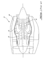
- FIG. 2 illustrates schematically an example of an improved turbofan and nacelle arrangement 30.
- the engine comprises a fan 12', a multistage compressor 14', a combustor 16' and a turbine section 18'.
- the arrangement shown in FIG. 2 includes a fan by-pass duct 32 that is considerably shorter.
- the fan by-pass duct 32 has an annular inlet 32a located downstream the fan 12' and an annular outlet 32b generally oriented substantially radially and at an intermediary location along the nacelle 34.
- all the by-pass flow exits through the fan by-pass outlet 32b at the intermediary location, where the flow is further accelerated by having a smaller cross-sectional area at the outlet 32b compared to the remainder of the by-pass duct 32.
- the nacelle 34 is designed with an aft section wider than the front section thereof.
- the aft section has an initially convex outer surface 34a which extends substantially outwardly adjacent to the outlet 32b of the fan by-pass duct 32.
- the nacelle 34 has an outer surface 34b which decreases in curvature and becomes concave towards the rear end of the engine.
- the radial jet exiting the bypass outlet 32b is deflected backwards over the convex portion 34a due to the Coanda effect. This generates a forward thrust component, which results from a very low static pressure distributed over the convex surface 34b.
- the intense ambient air entrainment over the curved surface increases significantly the jet cross section, thus the external entrainment surface.
- the intense entrainment of the ambient fluid bends the nacelle external flow stream lines inwards.
- the stream lines are forced back to the axial direction by the nacelle boat-tail, which generates a forward thrust component.
- the forward thrust component takes the form of a static pressure increase on the boat-tail. The additional thrust adds to the basic jet momentum.
- the fan by-pass air can be controlled using one or more auxiliary circumferential outlets 40 providing pressurized air deviated from a pressurized air source 42.
- the operation of the auxiliary outlet 40 is controlled by at least one valve 44.
- the pressurized air source 42 may include a bleed port from a stage of the multistage compressor 14' of the engine. Air is provided through the auxiliary outlet or outlets 40 for maintaining the fan 12' on the optimum working line.
- moving axially the forward lip, as a whole or as independent sectors, of the outlet 32b using mechanical, hydraulic, pneumatics or electrical actuators can control the effective cross section area of the bypass outlet 32b.
- a portion of the air that flows through the fan 12' is by-passed and ejected on the side of the nacelle 34.
- the deviated by-passed air then flows along a convex trajectory on the convex surface 34a.
- the air is in a zone referred to as the jet deflection zone.
- the jet amplification zone When the air reaches the other side of the aft section of the nacelle 34, it is in a zone referred to as the jet amplification zone.
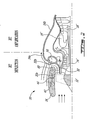
- FIG. 3 schematically illustrates a possible example of the arrangement of FIG. 2 during thrust reversal.
- some of the air is deviated in a cavity 50 within the convex surface 34a by a valve 54.
- the pressurized air is then sent through a plurality of outlet ports 52 adjacent to the outlet 32b of the by-pass duct 32.
- the air injected by the outlet ports 52 in the very low-pressure area of the convex surface 34a induces a large instability in the deflected jet, which determines the jet detachment from the convex surface 34a.
- the jet reattaches to the convex surface 34a as soon as the air supply into the cavity 50 is stopped.
- the air flow rate into the cavity 50 required to achieve complete jet detachment is very small compared to engine bypass flow due to particular instabilities of the Coanda effect. With the jet momentum axial component being zero, the engine net thrust becomes negative and equal to the engine air inlet flow momentum rate.
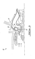
- FIG. 4 shows an alternative arrangement, in which the convex surface 34a has a plurality of flaps 60 located downstream the fan by-pass outlet 32b.
- the flaps 60 may pivot forward in order to increase the nacelle frontal area at low speed during takeoff.
- the improved arrangement 30 can provide an increased thrust and thrust efficiency in a turbofan gas turbine engine, all with a minimal weight increase. Also, the short mixing length of the jet with the ambient air provides a reduced noise radiation.
- the engine and the nacelle can be different from what is shown in the figures.
- the outlet of the by-pass duct may cover only one or more sectors of the nacelle circumference.
- the arrangement described for the engine by-pass flow may be implemented also for the engine core flow, i.e. the hot gases exiting the engine turbine are deflected through a radial slot over a convex external surface continued with a conical boat tail as in FIG. 5. Still other modifications which fall within the scope of the present invention will be apparent to those skilled in the art, in light of a review of this disclosure, and such modifications are intended to fall within the appended claims.
Landscapes
- Engineering & Computer Science (AREA)
- Chemical & Material Sciences (AREA)
- Combustion & Propulsion (AREA)
- Mechanical Engineering (AREA)
- General Engineering & Computer Science (AREA)
- Structures Of Non-Positive Displacement Pumps (AREA)
Applications Claiming Priority (1)
| Application Number | Priority Date | Filing Date | Title |
|---|---|---|---|
| US11/561,601 US7685805B2 (en) | 2006-11-20 | 2006-11-20 | Turbofan gas turbine engine and nacelle arrangement |
Publications (2)
| Publication Number | Publication Date |
|---|---|
| EP1925807A2 true EP1925807A2 (de) | 2008-05-28 |
| EP1925807A3 EP1925807A3 (de) | 2011-11-02 |
Family
ID=39092103
Family Applications (1)
| Application Number | Title | Priority Date | Filing Date |
|---|---|---|---|
| EP07254232A Withdrawn EP1925807A3 (de) | 2006-11-20 | 2007-10-25 | Gasturbinenmotor eines Turbolüfters mit Gondelanordnung |
Country Status (4)
| Country | Link |
|---|---|
| US (1) | US7685805B2 (de) |
| EP (1) | EP1925807A3 (de) |
| CA (1) | CA2669280C (de) |
| WO (1) | WO2008061336A1 (de) |
Families Citing this family (5)
| Publication number | Priority date | Publication date | Assignee | Title |
|---|---|---|---|---|
| FR2906573B1 (fr) * | 2006-09-29 | 2008-11-21 | Airbus France Sas | Nacelle de reacteur d'aeronef et aeronef comportant une telle nacelle |
| US8002520B2 (en) * | 2007-01-17 | 2011-08-23 | United Technologies Corporation | Core reflex nozzle for turbofan engine |
| US9200570B2 (en) * | 2012-02-24 | 2015-12-01 | Pratt & Whitney Canada Corp. | Air-cooled oil cooler for turbofan engine |
| US10501196B2 (en) | 2016-09-30 | 2019-12-10 | General Electric Company | Nacelle for an aircraft aft fan |
| US20180208297A1 (en) | 2017-01-20 | 2018-07-26 | General Electric Company | Nacelle for an aircraft aft fan |
Citations (2)
| Publication number | Priority date | Publication date | Assignee | Title |
|---|---|---|---|---|
| US3867813A (en) | 1971-10-05 | 1975-02-25 | Mtu Muenchen Gmbh | Turbojet engine for vertical or short take-off and landing airplanes |
| GB2070691A (en) | 1980-01-11 | 1981-09-09 | Rolls Royce | Radial splitter for reversible pitch fan propulsion unit. |
Family Cites Families (5)
| Publication number | Priority date | Publication date | Assignee | Title |
|---|---|---|---|---|
| FR1479705A (fr) * | 1966-05-11 | 1967-05-05 | Bristol Siddeley Engines Ltd | Perfectionnements aux moteurs comportant une turbine à gaz |
| GB1506588A (en) * | 1975-10-11 | 1978-04-05 | Rolls Royce | Gas turbine engine power plants for aircraft |
| US6968675B2 (en) * | 2002-10-29 | 2005-11-29 | Rohr, Inc. | Cascadeless fan thrust reverser with plume control |
| GB0321139D0 (en) * | 2003-09-10 | 2003-10-08 | Short Brothers Plc | A device |
| US7631483B2 (en) * | 2003-09-22 | 2009-12-15 | General Electric Company | Method and system for reduction of jet engine noise |
-
2006
- 2006-11-20 US US11/561,601 patent/US7685805B2/en active Active
-
2007
- 2007-10-22 WO PCT/CA2007/001866 patent/WO2008061336A1/en not_active Ceased
- 2007-10-22 CA CA2669280A patent/CA2669280C/en not_active Expired - Fee Related
- 2007-10-25 EP EP07254232A patent/EP1925807A3/de not_active Withdrawn
Patent Citations (2)
| Publication number | Priority date | Publication date | Assignee | Title |
|---|---|---|---|---|
| US3867813A (en) | 1971-10-05 | 1975-02-25 | Mtu Muenchen Gmbh | Turbojet engine for vertical or short take-off and landing airplanes |
| GB2070691A (en) | 1980-01-11 | 1981-09-09 | Rolls Royce | Radial splitter for reversible pitch fan propulsion unit. |
Also Published As
| Publication number | Publication date |
|---|---|
| WO2008061336A1 (en) | 2008-05-29 |
| CA2669280A1 (en) | 2008-05-29 |
| CA2669280C (en) | 2012-07-24 |
| US7685805B2 (en) | 2010-03-30 |
| US20080118348A1 (en) | 2008-05-22 |
| EP1925807A3 (de) | 2011-11-02 |
Similar Documents
| Publication | Publication Date | Title |
|---|---|---|
| JP5009581B2 (ja) | 可変ファン出口案内静翼を備えるターボファンガスタービンエンジン | |
| CN101021181B (zh) | 双旁路涡轮风扇发动机 | |
| CN100549398C (zh) | 推力矢量后部flade发动机 | |
| JP4559180B2 (ja) | 可変圧力比ファンシステムを有するガスタービンエンジン | |
| JP5220400B2 (ja) | ダクト燃焼式混成流ターボファン | |
| JP4619089B2 (ja) | 固定ジオメトリ入口を備えたfladeガスタービンエンジン | |
| US7137245B2 (en) | High area-ratio inter-turbine duct with inlet blowing | |
| US7509797B2 (en) | Thrust vectoring missile turbojet | |
| CN108930557B (zh) | 用于压缩机导叶前缘辅助导叶的方法及系统 | |
| US20110167792A1 (en) | Adaptive engine | |
| CN107013268B (zh) | 用于喷气发动机排气的压缩整流罩 | |
| EP3734053B1 (de) | Gebläse mit adaptivem vertikalhubmotor (avle) | |
| EP1780381A2 (de) | Mehrfach geschlitzter Turbinenverbindungskanal für Gasturbinen | |
| CN105408611A (zh) | 用于喷气发动机的次级喷嘴 | |
| EP3036422B1 (de) | Hochleistungsfähige konvergent-divergente düse | |
| JP5814651B2 (ja) | 排気流路に隣接する空洞のエジェクタパージ | |
| CA2669280C (en) | Turbofan gas turbine engine and nacelle arrangement | |
| US4306412A (en) | Jet engine and method of operating the same | |
| US20250043750A1 (en) | Inlets for gas turbine engine bypass duct heat exchangers |
Legal Events
| Date | Code | Title | Description |
|---|---|---|---|
| PUAI | Public reference made under article 153(3) epc to a published international application that has entered the european phase |
Free format text: ORIGINAL CODE: 0009012 |
|
| AK | Designated contracting states |
Kind code of ref document: A2 Designated state(s): AT BE BG CH CY CZ DE DK EE ES FI FR GB GR HU IE IS IT LI LT LU LV MC MT NL PL PT RO SE SI SK TR |
|
| AX | Request for extension of the european patent |
Extension state: AL BA HR MK RS |
|
| PUAL | Search report despatched |
Free format text: ORIGINAL CODE: 0009013 |
|
| AK | Designated contracting states |
Kind code of ref document: A3 Designated state(s): AT BE BG CH CY CZ DE DK EE ES FI FR GB GR HU IE IS IT LI LT LU LV MC MT NL PL PT RO SE SI SK TR |
|
| AX | Request for extension of the european patent |
Extension state: AL BA HR MK RS |
|
| RIC1 | Information provided on ipc code assigned before grant |
Ipc: F02K 3/068 20060101ALI20110927BHEP Ipc: F02K 3/04 20060101AFI20110927BHEP |
|
| 17P | Request for examination filed |
Effective date: 20120501 |
|
| AKX | Designation fees paid |
Designated state(s): DE FR GB |
|
| STAA | Information on the status of an ep patent application or granted ep patent |
Free format text: STATUS: THE APPLICATION IS DEEMED TO BE WITHDRAWN |
|
| 18D | Application deemed to be withdrawn |
Effective date: 20130502 |