EP1925747A2 - Element used to form breakwaters - Google Patents
Element used to form breakwaters Download PDFInfo
- Publication number
- EP1925747A2 EP1925747A2 EP06807848A EP06807848A EP1925747A2 EP 1925747 A2 EP1925747 A2 EP 1925747A2 EP 06807848 A EP06807848 A EP 06807848A EP 06807848 A EP06807848 A EP 06807848A EP 1925747 A2 EP1925747 A2 EP 1925747A2
- Authority
- EP
- European Patent Office
- Prior art keywords
- armor
- protrusions
- unit
- construct
- layers
- Prior art date
- Legal status (The legal status is an assumption and is not a legal conclusion. Google has not performed a legal analysis and makes no representation as to the accuracy of the status listed.)
- Granted
Links
Images





Classifications
-
- E—FIXED CONSTRUCTIONS
- E02—HYDRAULIC ENGINEERING; FOUNDATIONS; SOIL SHIFTING
- E02B—HYDRAULIC ENGINEERING
- E02B3/00—Engineering works in connection with control or use of streams, rivers, coasts, or other marine sites; Sealings or joints for engineering works in general
- E02B3/04—Structures or apparatus for, or methods of, protecting banks, coasts, or harbours
- E02B3/12—Revetment of banks, dams, watercourses, or the like, e.g. the sea-floor
- E02B3/129—Polyhedrons, tetrapods or similar bodies, whether or not threaded on strings
-
- E—FIXED CONSTRUCTIONS
- E02—HYDRAULIC ENGINEERING; FOUNDATIONS; SOIL SHIFTING
- E02B—HYDRAULIC ENGINEERING
- E02B3/00—Engineering works in connection with control or use of streams, rivers, coasts, or other marine sites; Sealings or joints for engineering works in general
- E02B3/04—Structures or apparatus for, or methods of, protecting banks, coasts, or harbours
- E02B3/12—Revetment of banks, dams, watercourses, or the like, e.g. the sea-floor
- E02B3/14—Preformed blocks or slabs for forming essentially continuous surfaces; Arrangements thereof
-
- Y—GENERAL TAGGING OF NEW TECHNOLOGICAL DEVELOPMENTS; GENERAL TAGGING OF CROSS-SECTIONAL TECHNOLOGIES SPANNING OVER SEVERAL SECTIONS OF THE IPC; TECHNICAL SUBJECTS COVERED BY FORMER USPC CROSS-REFERENCE ART COLLECTIONS [XRACs] AND DIGESTS
- Y02—TECHNOLOGIES OR APPLICATIONS FOR MITIGATION OR ADAPTATION AGAINST CLIMATE CHANGE
- Y02A—TECHNOLOGIES FOR ADAPTATION TO CLIMATE CHANGE
- Y02A10/00—TECHNOLOGIES FOR ADAPTATION TO CLIMATE CHANGE at coastal zones; at river basins
- Y02A10/11—Hard structures, e.g. dams, dykes or breakwaters
Definitions
- the present invention relates to an armor unit to construct armor layers of mound breakwaters, coastal revetments and groins for shore protection in maritime and hydraulic structures.
- the object of the invention is an armor unit to protect against large waves which has a basic cubic or parallelepiped shape characterized by one or more protrusions on its faces to prevent coupling between units and to increase interlocking with the underlayer of quarrystone.
- said concrete units for breakwater armor layers are not to be confused with those used for the construction of artificial reefs, since said armor units are designed to resist against large wave breaking and are characterized by specific features such as stability and strength while the artificial reefs are used to improve or protect marine habitats and almost any unit made of any material denser than water is considered suitable.
- Concrete armor units for mound breakwaters may be classified according to the design, the construction process and the resistant performance against the wave storms. There are three main methods to place armor units in the construction of an armor layer: (a) random placement, (b) placed in a single layer and (c) regular uniform placement.
- the armor units with random placement are the conventional armor units for substituting quarrystone, which are placed in more than one single layer and basically resist by gravity. Both simple and complex armor units can be found within the group of random placement units.
- Cubic and parallelepiped blocks are simple armor units, robust, easy to construct and flexible in their performance against the wave storms. Further, they do not undergo significant unit breaking fractures nor do they lose stability, and any errors in design usually increase armor erosion but rarely lead to the complete destruction of the breakwater.
- the group of complex armor units with random placement includes the so-called "Tetrapod” armor units, which have a higher stability coefficient as a result of their resistance due to interlocking. Nevertheless, the ease with which these units break if they are too large is considered a major drawback. They are brittle and are not resistant to large unit movements; therefore, any error in the design wave storm may lead to the unexpected complete destruction of the breakwater in the first intense storm after construction.
- the group of armor units with non-random placement (b) in a single layer includes the so-called “Accropode” and "Core-Loc” armor units which have a good interlocking between units, but have a relatively brittle structural performance because when any of the units fail, a progressive failure takes place. These armor units require less concrete but they must be placed with great care. Any error in the construction or calculation of the design wave storm can lead to the total destruction of the structure.
- the armor units with regular uniform placement may be either simple in shape like the so-called “Seabee” or “Hollow” shapes or more complex in shape such as the “Cob” or “Shed” ones.
- These units are usually placed in a single, uniform layer and their resistance depends fundamentally on gravity, friction and interlocking between the armor units, forming an assembly.
- these armor units are also quite resistant at the start of damage due to the tight interlocking between armor units, but they have a very brittle structural performance because they tend to present a progressive failure to destruction if any of the armor units fail.
- the armor unit described in the present invention being of the cubic and parallelepiped type usually manufactured for random placement, effectively solves the aforementioned drawbacks, and is considered an excellent solution for problems related to the self-arrangement and the decrease in friction.
- the improvement is achieved by means of cubic or parallelepiped armor units which feature protrusions to prevent coupling between the faces of the armor units and to diminish their tendency to self-arrangement while, at the same time, increasing the friction with the underlayer, which implies a reduction in run-up and overtopping rates.
- Said protrusions which can be located at any place on the outer surface of the unit, can also have different shapes, such as a frustoconical or truncated pyramidal shape. These different shapes of said protrusions provide the unit greater friction with the underlayer, made of natural or artificial quarrystone, because said protrusions tend to penetrate into the underlayer, generating a passive resistance which clearly improves the tendency of the cubic or parallelepiped blocks to place the faces parallel to the underlayer with an increased degree of interlocking between layers.
- the said protrusions of the armor unit prevent the face-to-face fitting caused by the movements of the armor units during the structure's lifetime, which leads to self-arrangement and reduces the porosity of the lower areas of the armor layer.
- the downward armor unit displacement is reduced as well as the displacement of armor units from the upper area, near the water level, which has an effect similar to erosion due to armor unit extraction.
- the reduction or suppression of the heterogeneous packing problem in the armor layer maintains the high hydraulic resistance capacity of the armor layer to armor unit extraction caused by wave attack.
- Another advantage of the invention is related to the possible fracture or erosion of the protrusions over time which results in a conventional cubic or parallelepiped unit; therefore, at the very least the invention will have the stability and robustness features of those conventional armor units.
- the armor unit to construct armor layers of mound breakwaters of the present invention based on a simple cubic or parallelepiped structure (2), has a series of protrusions (1) which can be located both on its side faces as well as at its vertices, or even both places at the same time.
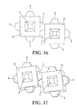
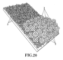
- Said protrusions (1) can likewise have different shapes such as pyramidal, conical, prismatic, cylindrical, spherical, etc., as well as any shape which aims to prevent the face-to-face fitting and the corresponding self-arrangement, as can be observed in Figures 16 to 19 , and to increase the friction with the underlayer (3) of the armor, as seen in Figure 21 .
- said protrusions (1) can also adopt different relative positions and sizes, as can be inferred by observing the figures.
- Alternative embodiment armor units are shown with more than one protrusion (1) per face or combinations of different protrusions (1) on the same unit or even the positioning of such protrusions both at the vertices and on the faces simultaneously.
- the dimensions of the protrusions (1) are small compared to those of the basic cube or parallelepiped (2) armor unit because their main purpose is to prevent their face-to-face fitting, maintaining the robustness of the conventional basic unit.
- said protrusions (1) have, for example, a volume such that the sum of the volumes of all is one order of magnitude less than the volume of the basic unit, in other words, less than 15%.
- the armor unit for the construction of the armor layer of mound breakwaters of the present invention usually has a cubic or parallelepiped fundamental structural base (2), with the majority of the volume made of a heavy material, such as concrete, reinforced or prestressed concrete and the like, and protrusions (1) including only a small part of the volume of the armor unit and made of a resistant material, such as concrete or steel, among others.
Landscapes
- Engineering & Computer Science (AREA)
- General Engineering & Computer Science (AREA)
- Environmental & Geological Engineering (AREA)
- Ocean & Marine Engineering (AREA)
- Mechanical Engineering (AREA)
- Civil Engineering (AREA)
- Structural Engineering (AREA)
- Chemical & Material Sciences (AREA)
- Crystallography & Structural Chemistry (AREA)
- Inorganic Chemistry (AREA)
- Revetment (AREA)
- Soil Working Implements (AREA)
Abstract
Description
- The present invention relates to an armor unit to construct armor layers of mound breakwaters, coastal revetments and groins for shore protection in maritime and hydraulic structures.
- Specifically, the object of the invention is an armor unit to protect against large waves which has a basic cubic or parallelepiped shape characterized by one or more protrusions on its faces to prevent coupling between units and to increase interlocking with the underlayer of quarrystone.
- The manufacture of artificial quarrystone for the construction of mound breakwaters and shore protection structures is a well-known problem. Until now, different solutions have been applied unsuccessfully, through the design of numerous armor units, generally made of concrete, to construct armor layers of mound breakwaters for protection against wind wave attack.
- It is worth highlighting that said concrete units for breakwater armor layers are not to be confused with those used for the construction of artificial reefs, since said armor units are designed to resist against large wave breaking and are characterized by specific features such as stability and strength while the artificial reefs are used to improve or protect marine habitats and almost any unit made of any material denser than water is considered suitable.
- Concrete armor units for mound breakwaters may be classified according to the design, the construction process and the resistant performance against the wave storms. There are three main methods to place armor units in the construction of an armor layer: (a) random placement, (b) placed in a single layer and (c) regular uniform placement.
- The armor units with random placement (a) are the conventional armor units for substituting quarrystone, which are placed in more than one single layer and basically resist by gravity. Both simple and complex armor units can be found within the group of random placement units.
- Cubic and parallelepiped blocks are simple armor units, robust, easy to construct and flexible in their performance against the wave storms. Further, they do not undergo significant unit breaking fractures nor do they lose stability, and any errors in design usually increase armor erosion but rarely lead to the complete destruction of the breakwater. However, these are units which have serious drawbacks as regards face-to-face fitting, which can result in significant permeability changes when the packing density increases in the lower areas causing a displacement of armor units from the upper areas (heterogeneous packing). Face-to-face fitting can also result in a reduction in friction with the underlayer and other problems derived from a certain self-arrangement of the armor units which should be placed and maintained in a random position.
- The group of complex armor units with random placement includes the so-called "Tetrapod" armor units, which have a higher stability coefficient as a result of their resistance due to interlocking. Nevertheless, the ease with which these units break if they are too large is considered a major drawback. They are brittle and are not resistant to large unit movements; therefore, any error in the design wave storm may lead to the unexpected complete destruction of the breakwater in the first intense storm after construction.
- The group of armor units with non-random placement (b) in a single layer includes the so-called "Accropode" and "Core-Loc" armor units which have a good interlocking between units, but have a relatively brittle structural performance because when any of the units fail, a progressive failure takes place. These armor units require less concrete but they must be placed with great care. Any error in the construction or calculation of the design wave storm can lead to the total destruction of the structure.
- Finally, the armor units with regular uniform placement (c) may be either simple in shape like the so-called "Seabee" or "Hollow" shapes or more complex in shape such as the "Cob" or "Shed" ones. These units are usually placed in a single, uniform layer and their resistance depends fundamentally on gravity, friction and interlocking between the armor units, forming an assembly. As in the previous case, these armor units are also quite resistant at the start of damage due to the tight interlocking between armor units, but they have a very brittle structural performance because they tend to present a progressive failure to destruction if any of the armor units fail.
- Focusing on the armor units with random placement, and more specifically on the mentioned cubic and parallelepiped blocks which, as stated earlier, are robust and easy to manufacture and are used along many coasts such as those of Spain, these units have serious drawbacks due to face-to-face fitting or self-arrangement. The reason is the parallelepiped design tends to pack armor units in the lower areas with small movements, forming armor layers with many planar faces coupled in the critical areas at sea level, decreasing the water friction on the slope of the mound and thus allowing a higher run-up and overtopping and even the flooding of the rear side of the breakwater if the wave is very large.
- The armor unit described in the present invention, being of the cubic and parallelepiped type usually manufactured for random placement, effectively solves the aforementioned drawbacks, and is considered an excellent solution for problems related to the self-arrangement and the decrease in friction.
- Specifically, the improvement is achieved by means of cubic or parallelepiped armor units which feature protrusions to prevent coupling between the faces of the armor units and to diminish their tendency to self-arrangement while, at the same time, increasing the friction with the underlayer, which implies a reduction in run-up and overtopping rates.
- Said protrusions, which can be located at any place on the outer surface of the unit, can also have different shapes, such as a frustoconical or truncated pyramidal shape. These different shapes of said protrusions provide the unit greater friction with the underlayer, made of natural or artificial quarrystone, because said protrusions tend to penetrate into the underlayer, generating a passive resistance which clearly improves the tendency of the cubic or parallelepiped blocks to place the faces parallel to the underlayer with an increased degree of interlocking between layers.
- In addition to the increased interlocking with the underlayer, the said protrusions of the armor unit prevent the face-to-face fitting caused by the movements of the armor units during the structure's lifetime, which leads to self-arrangement and reduces the porosity of the lower areas of the armor layer. Preventing the face-to-face fitting in the lower areas of the armor layer and the corresponding porosity reduction, the downward armor unit displacement is reduced as well as the displacement of armor units from the upper area, near the water level, which has an effect similar to erosion due to armor unit extraction. The reduction or suppression of the heterogeneous packing problem in the armor layer maintains the high hydraulic resistance capacity of the armor layer to armor unit extraction caused by wave attack.
- Finally, another advantage of the invention is related to the possible fracture or erosion of the protrusions over time which results in a conventional cubic or parallelepiped unit; therefore, at the very least the invention will have the stability and robustness features of those conventional armor units.
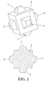
- To complement the description herein and to enhance the understanding the features of the invention according to a preferred practical embodiment thereof, a set of drawings is attached as an integral part of said description, in which the following is shown with an illustrative and non-limiting character:
-
Figure 1 shows a perspective view and a cross-section of the armor unit of the invention in a cubic embodiment, the protrusions of which are formed by truncated pyramids with a square section. -
Figure 2 shows a perspective view and two cross-sections of the armor unit of the invention, a longitudinal section and a cross-section, in a parallelepiped embodiment, the protrusions of which are formed by truncated pyramids with a square section. -
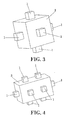
Figure 3 shows a perspective view of the armor unit of the invention in a cubic embodiment, the protrusions of which are formed by truncated pyramids with a square section. -
Figure 4 shows a perspective view of the armor unit of the invention in a parallelepiped embodiment with more than one protrusion on any of the faces. -
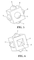
Figure 5 shows a perspective view of the armor unit ofFigure 1 with spherical protrusions. -
Figure 6 shows a perspective view of the armor unit ofFigure 1 with pyramidal protrusions with a square section. -
Figure 7 shows a perspective view of the armor unit ofFigure 1 with pyramidal protrusions with a triangular section. -
Figure 8 shows a perspective view of the armor unit ofFigure 1 with conical protrusions. -
Figure 9 shows a perspective view of the armor unit ofFigure 1 with cylindrical protrusions. -
Figure 10 shows a perspective view of the armor unit ofFigure 1 with frustoconical-shaped protrusions. -
Figure 11 shows a perspective view of the armor unit ofFigure 1 with different types of protrusions. -
Figure 12 shows a perspective view of the armor unit ofFigure 1 with spherical protrusions located at its vertices. -
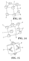
Figure 13 shows a perspective view of the armor unit ofFigure 1 with cubic protrusions located at its vertices. -
Figure 14 shows a perspective view of the armor unit ofFigure 1 with cubic protrusions on some faces and at its vertices. -
Figure 15 shows a perspective view of the armor unit ofFigure 1 with slender bar protrusions. -
Figures 16 to 19 show different views of the separating effect caused by the protrusions between cubic armor units such as those ofFigure 1 . -
Figure 20 shows a perspective view of a main armor area formed by cubic armor units such as those ofFigure 1 on an underlayer of quarrystone. -
Figure 21 shows a detail of the previousfigure (20 ) in which the armor unit penetrates the underlayer. - In view of the indicated figures, one can easily note how the armor unit to construct armor layers of mound breakwaters of the present invention, based on a simple cubic or parallelepiped structure (2), has a series of protrusions (1) which can be located both on its side faces as well as at its vertices, or even both places at the same time.
- Said protrusions (1) can likewise have different shapes such as pyramidal, conical, prismatic, cylindrical, spherical, etc., as well as any shape which aims to prevent the face-to-face fitting and the corresponding self-arrangement, as can be observed in
Figures 16 to 19 , and to increase the friction with the underlayer (3) of the armor, as seen inFigure 21 . - Furthermore, to obtain different degrees of separation between the armor units, said protrusions (1) can also adopt different relative positions and sizes, as can be inferred by observing the figures. Alternative embodiment armor units are shown with more than one protrusion (1) per face or combinations of different protrusions (1) on the same unit or even the positioning of such protrusions both at the vertices and on the faces simultaneously.
- In a preferred embodiment, the dimensions of the protrusions (1) are small compared to those of the basic cube or parallelepiped (2) armor unit because their main purpose is to prevent their face-to-face fitting, maintaining the robustness of the conventional basic unit.
- In a possible embodiment, said protrusions (1) have, for example, a volume such that the sum of the volumes of all is one order of magnitude less than the volume of the basic unit, in other words, less than 15%.
- In any case, the armor unit for the construction of the armor layer of mound breakwaters of the present invention usually has a cubic or parallelepiped fundamental structural base (2), with the majority of the volume made of a heavy material, such as concrete, reinforced or prestressed concrete and the like, and protrusions (1) including only a small part of the volume of the armor unit and made of a resistant material, such as concrete or steel, among others.
Claims (18)
- An armor unit to construct armor layers of mound breakwaters, revetments and groins for shore protection and hydraulic and maritime structures with a simple cubic or parallelepiped shape (2), characterized in that on at least one of its faces and/or vertices there is at least one protrusion (1) to prevent its coupling with other armor units during the construction process and throughout the structure's lifetime.
- An armor unit to construct armor layers of mound breakwaters according to claim 1, characterized in that the combined volume of said protrusions (1) is less than the total volume of the armor unit without said protrusions (1).
- An armor unit to construct armor layers of mound breakwaters according to claim 2, characterized in that the combined volume of said protrusions (1) is one order of magnitude lower than the volume of the armor unit without said protrusions (1).
- An armor unit to construct armor layers of mound breakwaters according to claim 3, characterized in that the combined volume of said protrusions (1) is less than 15% of the total volume of the unit without said protrusions (1).
- An armor unit to construct armor layers of mound breakwaters according to claim 1, characterized in that said protrusions (1) have a pyramidal or truncated pyramidal shape.
- An armor unit to construct armor layers of mound breakwaters according to claim 1, characterized in that said protrusions (1) have a conical or frustoconical shape.
- An armor unit to construct armor layers of mound breakwaters according to claim 1, characterized in that said protrusions (1) have a prismatic shape.
- An armor unit to construct armor layers of mound breakwaters according to claim 1, characterized in that said protrusions (1) have a cylindrical shape.
- An armor unit to construct armor layers of mound breakwaters according to claim 1, characterized in that said protrusions (1) have a spherical shape.
- An armor unit to construct armor layers of mound breakwaters according to claim 1, characterized in that it has a different number of protrusions (1) on each face.
- An armor unit to construct armor layers of mound breakwaters according to claim 1, characterized in that it has protrusions (1) with different shapes.
- An armor unit to construct armor layers of mound breakwaters according to claim 1, characterized in that said protrusions (1) located on the faces are centered on said faces.
- An armor unit to construct armor layers of mound breakwaters according to claim 1, characterized in that said protrusions (1) located on the faces are off-centered on said faces.
- An armor unit to construct armor layers of mound breakwaters according to claim 1, characterized in that said protrusions (1) located on the faces are not located in the same position on each of the said faces.
- An armor unit to construct armor layers of mound breakwaters according to claim 1, characterized in that it is manufactured from concrete.
- An armor unit to construct armor layers of mound breakwaters according to claim 1, characterized in that it is manufactured from reinforced or prestressed concrete.
- An armor unit to construct armor layers of mound breakwaters according to claim 1, characterized in that it is manufactured from concrete and the protrusions (1) are made of steel.
- An armor unit to construct armor layers of mound breakwaters according to claim 1, characterized in that it is manufactured from reinforced or prestressed concrete and the protrusions (1) are made of steel.
Priority Applications (1)
| Application Number | Priority Date | Filing Date | Title |
|---|---|---|---|
| PL06807848T PL1925747T3 (en) | 2005-07-11 | 2006-07-11 | Element used to form breakwaters |
Applications Claiming Priority (2)
| Application Number | Priority Date | Filing Date | Title |
|---|---|---|---|
| ES200501750A ES2264906B1 (en) | 2005-07-11 | 2005-07-11 | ELEMENT FOR THE FORMATION OF TABLETS. |
| PCT/ES2006/000395 WO2007006831A2 (en) | 2005-07-11 | 2006-07-11 | Element used to form breakwaters |
Publications (3)
| Publication Number | Publication Date |
|---|---|
| EP1925747A2 true EP1925747A2 (en) | 2008-05-28 |
| EP1925747A4 EP1925747A4 (en) | 2013-09-11 |
| EP1925747B1 EP1925747B1 (en) | 2017-09-20 |
Family
ID=37637531
Family Applications (1)
| Application Number | Title | Priority Date | Filing Date |
|---|---|---|---|
| EP06807848.4A Active EP1925747B1 (en) | 2005-07-11 | 2006-07-11 | Element used to form breakwaters |
Country Status (11)
| Country | Link |
|---|---|
| US (1) | US8529153B2 (en) |
| EP (1) | EP1925747B1 (en) |
| JP (1) | JP5118031B2 (en) |
| CN (1) | CN101258289B (en) |
| BR (1) | BRPI0615497B1 (en) |
| DK (1) | DK1925747T3 (en) |
| ES (2) | ES2264906B1 (en) |
| MA (1) | MA30617B1 (en) |
| PL (1) | PL1925747T3 (en) |
| PT (1) | PT1925747T (en) |
| WO (1) | WO2007006831A2 (en) |
Cited By (6)
| Publication number | Priority date | Publication date | Assignee | Title |
|---|---|---|---|---|
| WO2009030787A1 (en) | 2007-09-07 | 2009-03-12 | Sociedad Anonima Trabajos Y Obras | Mould for manufacturing concrete cubipods |
| CN102296569A (en) * | 2011-07-12 | 2011-12-28 | 长乐杭辉日用品有限公司 | Novel sea-reclamation building and installation process thereof |
| ES2385696A1 (en) * | 2008-07-17 | 2012-07-30 | Berenguer Ingenieros S.L. | Artificial piece for the formation of mantos of protection of one or more layers of the breakwater dies and the defenses of coastal, lagoon and river rivers (Machine-translation by Google Translate, not legally binding) |
| WO2016125127A1 (en) * | 2015-02-06 | 2016-08-11 | Universita' Degli Studi Di Salerno | Artificial unit configured to build hydraulic structures, in particular maritime structures |
| EP2118381A4 (en) * | 2007-01-31 | 2016-12-07 | Us Government | UNIT OF ARMOR |
| IT201700118506A1 (en) * | 2017-10-19 | 2019-04-19 | Tommaso Elia | Artificial breakwater form in the shape of a sea urchin |
Families Citing this family (13)
| Publication number | Priority date | Publication date | Assignee | Title |
|---|---|---|---|---|
| WO2010104342A2 (en) * | 2009-03-11 | 2010-09-16 | 우암종합건설(주) | Porous underwater breakwater for preventing shore erosion and forming a fishing ground, and method for producing environmentally-friendly blocks for the underwater breakwater |
| FR3003278B1 (en) * | 2013-03-15 | 2017-12-08 | Inouco | BLOCK FOR PROTECTING MARITIME AND / OR RIVER WORKS, AND STRUCTURE FOR PROTECTING MARITIME AND / OR RIVER WORKS COMPRISING A PLURALITY OF SUCH BLOCKS |
| KR101698061B1 (en) * | 2016-03-28 | 2017-01-19 | 한국해양과학기술원 | Armor unit against high wave with reinforcement structure |
| CN105951853B (en) * | 2016-05-20 | 2017-11-14 | 四川大学 | Modified tetrahedron for dam project is jettisoninged material |
| CN106284208B (en) * | 2016-11-01 | 2018-04-13 | 重庆水利电力职业技术学院 | A kind of shock resistance dykes and dams |
| USD849850S1 (en) * | 2017-06-02 | 2019-05-28 | David D. Holowka | Building block set for toy and hobby |
| KR102145727B1 (en) * | 2018-09-10 | 2020-08-19 | (주)아이엠 | Floating apparatus for solar generation of electric power on water |
| KR102145730B1 (en) * | 2018-09-10 | 2020-08-19 | (주)아이엠 | Floating apparatus for solar generation of electric power on water |
| CN109356094A (en) * | 2018-12-12 | 2019-02-19 | 交通运输部天津水运工程科学研究所 | An eco-friendly pyramidal beach protection body and a beach protection structure using the same |
| NL2023195B1 (en) | 2019-05-24 | 2020-12-02 | Koninklijke Bam Groep Nv | Crest element for a breakwater, armour layer assembly for a breakwater, breakwater, method of cresting a breakwater, and method of providing an armour on a breakwater. |
| US11555286B1 (en) * | 2022-02-25 | 2023-01-17 | Natrx, Inc. | Stabilizing structural fills |
| CN117562011B (en) * | 2024-01-04 | 2024-05-03 | 水利部交通运输部国家能源局南京水利科学研究院 | Ecological type wave-eliminating reef body |
| CN117552368B (en) * | 2024-01-09 | 2024-03-22 | 山东科技大学 | Prefabricated masonry structure for water conservancy project infrastructure and preparation method thereof |
Family Cites Families (38)
| Publication number | Priority date | Publication date | Assignee | Title |
|---|---|---|---|---|
| NL300238A (en) * | 1900-01-01 | |||
| US3374917A (en) * | 1964-01-09 | 1968-03-26 | Constantine T. Troy | Interlocking structural elements |
| JPS5132892B1 (en) * | 1967-01-07 | 1976-09-16 | ||
| US3461574A (en) * | 1967-07-10 | 1969-08-19 | Intrinsics Inc | Educational toy |
| NL7116401A (en) * | 1971-11-29 | 1973-06-01 | ||
| US3822499A (en) * | 1972-05-30 | 1974-07-09 | Vos J De | Toy building block suitable for a pad, raft or the like |
| JPS5063317U (en) * | 1973-10-04 | 1975-06-09 | ||
| JPS51738A (en) * | 1974-06-24 | 1976-01-06 | Shiiberu Chosa Setsukei Jimush | SHOHABUROTSUKU |
| FR2449164A1 (en) * | 1979-02-14 | 1980-09-12 | Sogreah | ARTIFICIAL BLOCK FOR MARITIME AND RIVER STRUCTURES |
| US4411555A (en) * | 1979-07-17 | 1983-10-25 | Minvielle Monique L | Draining, irrigating and dispersing mass |
| JPS57184109A (en) * | 1981-05-06 | 1982-11-12 | Masayoshi Nagano | Breakwater block |
| USD283635S (en) * | 1983-05-09 | 1986-04-29 | Tomy Kogyo Company, Inc. | Toy construction piece |
| JPS6062534U (en) * | 1983-10-04 | 1985-05-01 | 富沢 進 | Tetra Pot (registered trademark) |
| US4594023A (en) * | 1984-10-11 | 1986-06-10 | Neill Raymond J O | Breakwater construction element |
| ES282009Y (en) * | 1984-10-16 | 1985-11-01 | Agroman, Empresa Constructora S.A. | PIECE FOR ARTIFICIAL POCKETS |
| USD296342S (en) * | 1984-11-30 | 1988-06-21 | Interlego A.G. | Toy construction piece |
| JPS61173523U (en) * | 1985-04-18 | 1986-10-28 | ||
| US5145285A (en) * | 1990-05-15 | 1992-09-08 | Fox Nathaniel S | Discontinuous structural reinforcing elements and method of reinforcing and improving soils and other construction materials |
| US5190403A (en) * | 1991-06-07 | 1993-03-02 | Atkinson-Mcdougal Corporation | Erosion protection device |
| CN1030849C (en) * | 1991-06-20 | 1996-01-31 | 万逸民 | Breakwater concrete block |
| ES2043559B1 (en) * | 1992-06-05 | 1994-07-01 | Univ Sevilla | REEF PROTECTION MODULE. |
| USD358858S (en) * | 1993-05-03 | 1995-05-30 | Mcgreevy Robert K | Ball |
| US5441362A (en) * | 1993-09-30 | 1995-08-15 | The United States Of America As Represented By The Secretary Of The Army | Concrete armor unit for protecting coastal and hydraulic structures and shorelines |
| USD359315S (en) * | 1993-12-16 | 1995-06-13 | Philip & Tacey | Toy building block |
| US5556230A (en) * | 1994-10-19 | 1996-09-17 | U.S. Army Corps Of Engineers As Represented By The Secretary Of The Army | Concrete armor unit for the protection of coastal, shore lines and hydraulic structures |
| USD377396S (en) * | 1995-01-27 | 1997-01-14 | Edrasco | Construction block |
| US5921710A (en) * | 1997-02-27 | 1999-07-13 | Scales; John M. | Revetment blocks and method |
| US6921314B2 (en) * | 1998-03-13 | 2005-07-26 | George R. Miller | Intercleaving spatially dichotomized polyhedral building blocks and extensions |
| JP2979224B2 (en) * | 1998-04-20 | 1999-11-15 | 一彦 北川 | Basket-shaped frame and natural basket block |
| US6059490A (en) * | 1998-05-05 | 2000-05-09 | Kauppi; Frederick J. | Hydraulic energy dissipating offset stepped spillway and methods of constructing and using the same |
| KR100335334B1 (en) * | 1998-09-18 | 2002-11-27 | 한국해양연구원 | Optimized middle armor concrete block |
| JP2001087779A (en) * | 1999-09-22 | 2001-04-03 | Daikichi Suematsu | Foot protection block for water purification and water purifying foot protection sutructure using the foot protection block for water purification |
| USD437366S1 (en) * | 2000-06-29 | 2001-02-06 | Peter Stemmler | Interlocking building cube |
| KR200228767Y1 (en) * | 2001-01-17 | 2001-07-19 | 원 회 양 | The wave dissipating block for the covering breakwater |
| US6669403B2 (en) * | 2002-04-06 | 2003-12-30 | Wave Control Systems Inc. | Wave attenuator |
| DK1540087T3 (en) * | 2002-07-24 | 2015-12-07 | Konink Bam Groep Nv | Protective element for a breakwater or wave inhibitory construction |
| FR2863632B1 (en) * | 2003-12-12 | 2007-01-26 | Dept De La Martinique | WORK FOR LITTORAL PROTECTION |
| AP2927A (en) * | 2007-01-31 | 2014-06-30 | Us Government | Armor unit |
-
2005
- 2005-07-11 ES ES200501750A patent/ES2264906B1/en not_active Expired - Fee Related
-
2006
- 2006-07-11 US US11/995,371 patent/US8529153B2/en active Active
- 2006-07-11 WO PCT/ES2006/000395 patent/WO2007006831A2/en not_active Ceased
- 2006-07-11 EP EP06807848.4A patent/EP1925747B1/en active Active
- 2006-07-11 BR BRPI0615497-2A patent/BRPI0615497B1/en active IP Right Grant
- 2006-07-11 ES ES06807848.4T patent/ES2651891T3/en active Active
- 2006-07-11 CN CN200680032745XA patent/CN101258289B/en active Active
- 2006-07-11 PL PL06807848T patent/PL1925747T3/en unknown
- 2006-07-11 PT PT68078484T patent/PT1925747T/en unknown
- 2006-07-11 DK DK06807848.4T patent/DK1925747T3/en active
- 2006-07-11 JP JP2008520897A patent/JP5118031B2/en active Active
-
2008
- 2008-02-07 MA MA30622A patent/MA30617B1/en unknown
Cited By (7)
| Publication number | Priority date | Publication date | Assignee | Title |
|---|---|---|---|---|
| EP2118381A4 (en) * | 2007-01-31 | 2016-12-07 | Us Government | UNIT OF ARMOR |
| WO2009030787A1 (en) | 2007-09-07 | 2009-03-12 | Sociedad Anonima Trabajos Y Obras | Mould for manufacturing concrete cubipods |
| ES2385696A1 (en) * | 2008-07-17 | 2012-07-30 | Berenguer Ingenieros S.L. | Artificial piece for the formation of mantos of protection of one or more layers of the breakwater dies and the defenses of coastal, lagoon and river rivers (Machine-translation by Google Translate, not legally binding) |
| CN102296569A (en) * | 2011-07-12 | 2011-12-28 | 长乐杭辉日用品有限公司 | Novel sea-reclamation building and installation process thereof |
| CN102296569B (en) * | 2011-07-12 | 2013-06-19 | 长乐杭辉日用品有限公司 | Sea-reclamation building and installation process thereof |
| WO2016125127A1 (en) * | 2015-02-06 | 2016-08-11 | Universita' Degli Studi Di Salerno | Artificial unit configured to build hydraulic structures, in particular maritime structures |
| IT201700118506A1 (en) * | 2017-10-19 | 2019-04-19 | Tommaso Elia | Artificial breakwater form in the shape of a sea urchin |
Also Published As
| Publication number | Publication date |
|---|---|
| CN101258289B (en) | 2010-12-15 |
| PL1925747T3 (en) | 2018-06-29 |
| ES2264906A1 (en) | 2007-01-16 |
| BRPI0615497A2 (en) | 2011-05-17 |
| JP5118031B2 (en) | 2013-01-16 |
| EP1925747B1 (en) | 2017-09-20 |
| PT1925747T (en) | 2017-12-21 |
| MA30617B1 (en) | 2009-08-03 |
| JP2009500548A (en) | 2009-01-08 |
| WO2007006831A3 (en) | 2007-04-12 |
| BRPI0615497B1 (en) | 2018-05-29 |
| US20080286045A1 (en) | 2008-11-20 |
| CN101258289A (en) | 2008-09-03 |
| US8529153B2 (en) | 2013-09-10 |
| ES2264906B1 (en) | 2008-01-01 |
| ES2651891T3 (en) | 2018-01-30 |
| DK1925747T3 (en) | 2018-01-08 |
| EP1925747A4 (en) | 2013-09-11 |
| WO2007006831A2 (en) | 2007-01-18 |
Similar Documents
| Publication | Publication Date | Title |
|---|---|---|
| US8529153B2 (en) | Element used to form breakwaters | |
| US8132985B2 (en) | Armor unit | |
| RU2126867C1 (en) | Reinforced block | |
| CN213014131U (en) | An artificial algae reef type ecological coastal protection structure | |
| US10400406B2 (en) | Wave dissipation systems, modules and methods for constructing the same | |
| US9915049B2 (en) | Cost-efficient armor unit | |
| EP0394175B1 (en) | Mound breakwater | |
| US20260028789A1 (en) | Device and method for coastal erosion mitigation using concrete dome structures | |
| CN112832190A (en) | Coral island reef wave-proof wall structure and construction method thereof | |
| CN219195826U (en) | Wave-absorbing and wave-preventing building block for delta seawall | |
| CN217104906U (en) | Sheet pile vertical wall and artificial fish reef combined offshore sea wall in front of damageable sea wall | |
| CN102061680A (en) | Mound breakwater | |
| WO1994001624A1 (en) | Revetment unit and method for protecting shoreline or waterway | |
| JPS60261815A (en) | Method of protecting weir body | |
| JPH01260112A (en) | Non-concrete flexible structural part and construction of seaside facility therewith | |
| JPS60261816A (en) | Method of protecting weir body | |
| HK1001543B (en) | Concrete armor unit to protect coastal and hydraulic structures and shorelines |
Legal Events
| Date | Code | Title | Description |
|---|---|---|---|
| PUAI | Public reference made under article 153(3) epc to a published international application that has entered the european phase |
Free format text: ORIGINAL CODE: 0009012 |
|
| 17P | Request for examination filed |
Effective date: 20080211 |
|
| AK | Designated contracting states |
Kind code of ref document: A2 Designated state(s): AT BE BG CH CY CZ DE DK EE ES FI FR GB GR HU IE IS IT LI LT LU LV MC NL PL PT RO SE SI SK TR |
|
| RIN1 | Information on inventor provided before grant (corrected) |
Inventor name: MEDINA FOLGADO, JOSEP RAMON Inventor name: GOMEZ MARTIN, MARIA ESTHER |
|
| DAX | Request for extension of the european patent (deleted) | ||
| A4 | Supplementary search report drawn up and despatched |
Effective date: 20130808 |
|
| RIC1 | Information provided on ipc code assigned before grant |
Ipc: E02B 3/14 20060101AFI20130802BHEP |
|
| 17Q | First examination report despatched |
Effective date: 20160223 |
|
| RIC1 | Information provided on ipc code assigned before grant |
Ipc: E02B 3/12 20060101ALI20160607BHEP Ipc: E02B 3/14 20060101AFI20160607BHEP |
|
| STAA | Information on the status of an ep patent application or granted ep patent |
Free format text: STATUS: EXAMINATION IS IN PROGRESS |
|
| GRAP | Despatch of communication of intention to grant a patent |
Free format text: ORIGINAL CODE: EPIDOSNIGR1 |
|
| STAA | Information on the status of an ep patent application or granted ep patent |
Free format text: STATUS: GRANT OF PATENT IS INTENDED |
|
| INTG | Intention to grant announced |
Effective date: 20170411 |
|
| GRAS | Grant fee paid |
Free format text: ORIGINAL CODE: EPIDOSNIGR3 |
|
| GRAA | (expected) grant |
Free format text: ORIGINAL CODE: 0009210 |
|
| STAA | Information on the status of an ep patent application or granted ep patent |
Free format text: STATUS: THE PATENT HAS BEEN GRANTED |
|
| AK | Designated contracting states |
Kind code of ref document: B1 Designated state(s): AT BE BG CH CY CZ DE DK EE ES FI FR GB GR HU IE IS IT LI LT LU LV MC NL PL PT RO SE SI SK TR |
|
| REG | Reference to a national code |
Ref country code: GB Ref legal event code: FG4D |
|
| REG | Reference to a national code |
Ref country code: CH Ref legal event code: EP |
|
| REG | Reference to a national code |
Ref country code: AT Ref legal event code: REF Ref document number: 930206 Country of ref document: AT Kind code of ref document: T Effective date: 20171015 |
|
| REG | Reference to a national code |
Ref country code: IE Ref legal event code: FG4D |
|
| REG | Reference to a national code |
Ref country code: DE Ref legal event code: R096 Ref document number: 602006053673 Country of ref document: DE |
|
| REG | Reference to a national code |
Ref country code: PT Ref legal event code: SC4A Ref document number: 1925747 Country of ref document: PT Date of ref document: 20171221 Kind code of ref document: T Free format text: AVAILABILITY OF NATIONAL TRANSLATION Effective date: 20171214 |
|
| REG | Reference to a national code |
Ref country code: NL Ref legal event code: FP |
|
| REG | Reference to a national code |
Ref country code: SE Ref legal event code: TRGR |
|
| REG | Reference to a national code |
Ref country code: DK Ref legal event code: T3 Effective date: 20180104 |
|
| REG | Reference to a national code |
Ref country code: ES Ref legal event code: FG2A Ref document number: 2651891 Country of ref document: ES Kind code of ref document: T3 Effective date: 20180130 |
|
| PG25 | Lapsed in a contracting state [announced via postgrant information from national office to epo] |
Ref country code: LT Free format text: LAPSE BECAUSE OF FAILURE TO SUBMIT A TRANSLATION OF THE DESCRIPTION OR TO PAY THE FEE WITHIN THE PRESCRIBED TIME-LIMIT Effective date: 20170920 |
|
| REG | Reference to a national code |
Ref country code: LT Ref legal event code: MG4D |
|
| REG | Reference to a national code |
Ref country code: AT Ref legal event code: MK05 Ref document number: 930206 Country of ref document: AT Kind code of ref document: T Effective date: 20170920 |
|
| PG25 | Lapsed in a contracting state [announced via postgrant information from national office to epo] |
Ref country code: BG Free format text: LAPSE BECAUSE OF FAILURE TO SUBMIT A TRANSLATION OF THE DESCRIPTION OR TO PAY THE FEE WITHIN THE PRESCRIBED TIME-LIMIT Effective date: 20171220 Ref country code: LV Free format text: LAPSE BECAUSE OF FAILURE TO SUBMIT A TRANSLATION OF THE DESCRIPTION OR TO PAY THE FEE WITHIN THE PRESCRIBED TIME-LIMIT Effective date: 20170920 |
|
| PG25 | Lapsed in a contracting state [announced via postgrant information from national office to epo] |
Ref country code: RO Free format text: LAPSE BECAUSE OF FAILURE TO SUBMIT A TRANSLATION OF THE DESCRIPTION OR TO PAY THE FEE WITHIN THE PRESCRIBED TIME-LIMIT Effective date: 20170920 Ref country code: CZ Free format text: LAPSE BECAUSE OF FAILURE TO SUBMIT A TRANSLATION OF THE DESCRIPTION OR TO PAY THE FEE WITHIN THE PRESCRIBED TIME-LIMIT Effective date: 20170920 |
|
| PG25 | Lapsed in a contracting state [announced via postgrant information from national office to epo] |
Ref country code: SK Free format text: LAPSE BECAUSE OF FAILURE TO SUBMIT A TRANSLATION OF THE DESCRIPTION OR TO PAY THE FEE WITHIN THE PRESCRIBED TIME-LIMIT Effective date: 20170920 Ref country code: IS Free format text: LAPSE BECAUSE OF FAILURE TO SUBMIT A TRANSLATION OF THE DESCRIPTION OR TO PAY THE FEE WITHIN THE PRESCRIBED TIME-LIMIT Effective date: 20180120 Ref country code: AT Free format text: LAPSE BECAUSE OF FAILURE TO SUBMIT A TRANSLATION OF THE DESCRIPTION OR TO PAY THE FEE WITHIN THE PRESCRIBED TIME-LIMIT Effective date: 20170920 Ref country code: EE Free format text: LAPSE BECAUSE OF FAILURE TO SUBMIT A TRANSLATION OF THE DESCRIPTION OR TO PAY THE FEE WITHIN THE PRESCRIBED TIME-LIMIT Effective date: 20170920 |
|
| REG | Reference to a national code |
Ref country code: GR Ref legal event code: EP Ref document number: 20170403467 Country of ref document: GR Effective date: 20180518 |
|
| REG | Reference to a national code |
Ref country code: DE Ref legal event code: R097 Ref document number: 602006053673 Country of ref document: DE |
|
| REG | Reference to a national code |
Ref country code: FR Ref legal event code: PLFP Year of fee payment: 13 |
|
| PLBE | No opposition filed within time limit |
Free format text: ORIGINAL CODE: 0009261 |
|
| STAA | Information on the status of an ep patent application or granted ep patent |
Free format text: STATUS: NO OPPOSITION FILED WITHIN TIME LIMIT |
|
| 26N | No opposition filed |
Effective date: 20180621 |
|
| PG25 | Lapsed in a contracting state [announced via postgrant information from national office to epo] |
Ref country code: SI Free format text: LAPSE BECAUSE OF FAILURE TO SUBMIT A TRANSLATION OF THE DESCRIPTION OR TO PAY THE FEE WITHIN THE PRESCRIBED TIME-LIMIT Effective date: 20170920 |
|
| REG | Reference to a national code |
Ref country code: CH Ref legal event code: PL |
|
| PG25 | Lapsed in a contracting state [announced via postgrant information from national office to epo] |
Ref country code: MC Free format text: LAPSE BECAUSE OF FAILURE TO SUBMIT A TRANSLATION OF THE DESCRIPTION OR TO PAY THE FEE WITHIN THE PRESCRIBED TIME-LIMIT Effective date: 20170920 Ref country code: LU Free format text: LAPSE BECAUSE OF NON-PAYMENT OF DUE FEES Effective date: 20180711 |
|
| PG25 | Lapsed in a contracting state [announced via postgrant information from national office to epo] |
Ref country code: LI Free format text: LAPSE BECAUSE OF NON-PAYMENT OF DUE FEES Effective date: 20180731 Ref country code: CH Free format text: LAPSE BECAUSE OF NON-PAYMENT OF DUE FEES Effective date: 20180731 |
|
| PG25 | Lapsed in a contracting state [announced via postgrant information from national office to epo] |
Ref country code: HU Free format text: LAPSE BECAUSE OF FAILURE TO SUBMIT A TRANSLATION OF THE DESCRIPTION OR TO PAY THE FEE WITHIN THE PRESCRIBED TIME-LIMIT; INVALID AB INITIO Effective date: 20060711 |
|
| PG25 | Lapsed in a contracting state [announced via postgrant information from national office to epo] |
Ref country code: CY Free format text: LAPSE BECAUSE OF FAILURE TO SUBMIT A TRANSLATION OF THE DESCRIPTION OR TO PAY THE FEE WITHIN THE PRESCRIBED TIME-LIMIT Effective date: 20170920 |
|
| PGFP | Annual fee paid to national office [announced via postgrant information from national office to epo] |
Ref country code: PT Payment date: 20250918 Year of fee payment: 20 Ref country code: ES Payment date: 20250731 Year of fee payment: 20 Ref country code: FI Payment date: 20250925 Year of fee payment: 20 |
|
| PGFP | Annual fee paid to national office [announced via postgrant information from national office to epo] |
Ref country code: DE Payment date: 20250929 Year of fee payment: 20 Ref country code: DK Payment date: 20250925 Year of fee payment: 20 |
|
| PGFP | Annual fee paid to national office [announced via postgrant information from national office to epo] |
Ref country code: GR Payment date: 20250926 Year of fee payment: 20 |
|
| PGFP | Annual fee paid to national office [announced via postgrant information from national office to epo] |
Ref country code: PL Payment date: 20250926 Year of fee payment: 20 Ref country code: TR Payment date: 20250924 Year of fee payment: 20 Ref country code: NL Payment date: 20250926 Year of fee payment: 20 Ref country code: IT Payment date: 20250919 Year of fee payment: 20 |
|
| PGFP | Annual fee paid to national office [announced via postgrant information from national office to epo] |
Ref country code: BE Payment date: 20250929 Year of fee payment: 20 Ref country code: GB Payment date: 20250929 Year of fee payment: 20 |
|
| PGFP | Annual fee paid to national office [announced via postgrant information from national office to epo] |
Ref country code: FR Payment date: 20250925 Year of fee payment: 20 |
|
| PGFP | Annual fee paid to national office [announced via postgrant information from national office to epo] |
Ref country code: SE Payment date: 20250927 Year of fee payment: 20 |
|
| PGFP | Annual fee paid to national office [announced via postgrant information from national office to epo] |
Ref country code: IE Payment date: 20250929 Year of fee payment: 20 |