EP1925688A2 - Appareil et méthode de métalisation d'un componant métallique - Google Patents
Appareil et méthode de métalisation d'un componant métallique Download PDFInfo
- Publication number
- EP1925688A2 EP1925688A2 EP07119585A EP07119585A EP1925688A2 EP 1925688 A2 EP1925688 A2 EP 1925688A2 EP 07119585 A EP07119585 A EP 07119585A EP 07119585 A EP07119585 A EP 07119585A EP 1925688 A2 EP1925688 A2 EP 1925688A2
- Authority
- EP
- European Patent Office
- Prior art keywords
- coolant
- metallization
- component
- wall
- coated
- Prior art date
- Legal status (The legal status is an assumption and is not a legal conclusion. Google has not performed a legal analysis and makes no representation as to the accuracy of the status listed.)
- Granted
Links
Images
Classifications
-
- C—CHEMISTRY; METALLURGY
- C23—COATING METALLIC MATERIAL; COATING MATERIAL WITH METALLIC MATERIAL; CHEMICAL SURFACE TREATMENT; DIFFUSION TREATMENT OF METALLIC MATERIAL; COATING BY VACUUM EVAPORATION, BY SPUTTERING, BY ION IMPLANTATION OR BY CHEMICAL VAPOUR DEPOSITION, IN GENERAL; INHIBITING CORROSION OF METALLIC MATERIAL OR INCRUSTATION IN GENERAL
- C23C—COATING METALLIC MATERIAL; COATING MATERIAL WITH METALLIC MATERIAL; SURFACE TREATMENT OF METALLIC MATERIAL BY DIFFUSION INTO THE SURFACE, BY CHEMICAL CONVERSION OR SUBSTITUTION; COATING BY VACUUM EVAPORATION, BY SPUTTERING, BY ION IMPLANTATION OR BY CHEMICAL VAPOUR DEPOSITION, IN GENERAL
- C23C4/00—Coating by spraying the coating material in the molten state, e.g. by flame, plasma or electric discharge
- C23C4/12—Coating by spraying the coating material in the molten state, e.g. by flame, plasma or electric discharge characterised by the method of spraying
- C23C4/129—Flame spraying
-
- B—PERFORMING OPERATIONS; TRANSPORTING
- B05—SPRAYING OR ATOMISING IN GENERAL; APPLYING FLUENT MATERIALS TO SURFACES, IN GENERAL
- B05B—SPRAYING APPARATUS; ATOMISING APPARATUS; NOZZLES
- B05B7/00—Spraying apparatus for discharge of liquids or other fluent materials from two or more sources, e.g. of liquid and air, of powder and gas
- B05B7/16—Spraying apparatus for discharge of liquids or other fluent materials from two or more sources, e.g. of liquid and air, of powder and gas incorporating means for heating or cooling the material to be sprayed
- B05B7/20—Spraying apparatus for discharge of liquids or other fluent materials from two or more sources, e.g. of liquid and air, of powder and gas incorporating means for heating or cooling the material to be sprayed by flame or combustion
Definitions
- the present invention relates to an apparatus for the metallization of metal components and a relative method of metallization and in particular, an apparatus and a method for the metallization of light alloys.
- light alloy components such as aluminium alloys
- the process of application on light alloy substrates causes an excessive surface heating, given by the impact of the particles (and by the partial transformation of their kinetic energy into heat) and by the impact of the combustion gas at a high temperature. Since the mechanical properties of light alloys quickly decay in the presence of relatively low temperatures (a little above 120°C), with any method used the metallization imparts no surface improvement to light alloy components.
- the problem of the present invention is to solve the limits and disadvantages mentioned with reference to the prior art.
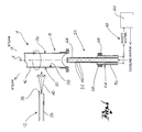
- reference numeral 4 globally denotes an apparatus for metallization, suitable for providing a metal coating on a component 8, preferably a component of metal material in a light alloy.
- Apparatus 4 comprises means 12 for depositing a metal layer on a component, said deposition means 12 being directly facing a wall to be coated 16 of said component 8 so as to address a flow of metal material on a first surface 20 of said wall to be coated 16.
- said apparatus 4 comprises a cooling head 24 suitable for sending a cooling fluid flow on a second surface 28 of said wall to be coated 16, the second surface 28 being opposite the first surface 20 so as to not be impinged by the flow of metal material.
- component 8 may be a globally cylindrical component, wherein the first surface 20 consists of the outer side surface or portion thereof and the second surface 28 consists of the inner side surface or portion thereof.
- the deposition means 12 comprise a metallization gun 29 suitable for performing an HVOF (High Velocity Oxyfuel) method for metal coating.
- HVOF High Velocity Oxyfuel
- the combustible, typically paraffin and the comburent, typically oxygen get mixed and they atomise after passing through respective inlet orifices 30, 31 inside the combustion chamber 32 wherein the combustion takes place by the use of a spark plug 32'.
- Pressure in the combustion chamber 32 is monitored constantly to ensure proper combustion and constant pressure.
- the particle speed is directly related to the pressure of chamber 32; the gun comprises a converging-diverging nozzle 33 having such shape and size as to create a supersonic jet.
- Particles of metal powder, which make up the coating are introduced downstream of the diverging portion through inlets 34 and are then brought to such temperature as to make them partially plastic.
- a flow of metal particles 40 at high speed is therefore obtained wherein the metal particles exit at a high speed from an outlet 35 of gun 29 and thus impact against the wall to be coated, thus transforming the high kinetic energy into a plastic deformation and heat during the impact and creating the adhesion to the component substrate.
- Gun 29 preferably comprises also inlet and outlet ducts 36, 38 for a cooling circuit.
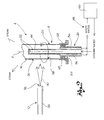
- the cooling head 24 comprises a delivery duct 44, in fluid connection to a cooling fluid circuit 48, said delivery duct 44 being provided with at least one delivery hole 52 for the dispersion of coolant on said second surface 28 of the wall to be coated 16.
- said delivery duct 44 comprises a plurality of delivery holes 52 for fluid dispersion, said holes 52 being for example equally spaced along a prevailing extension axis X of the delivery duct 44.
- the delivery holes 52 are arranged according to an axial-symmetric arrangement relative to said prevailing extension axis X of the delivery duct 44.
- the cooling head 24 comprises at least one collecting duct 56 suitable for collecting the coolant after this has come into contact with the second surface 28 of the wall to be coated 16 and for conveying it in removal from said head 24 in said cooling circuit 48.
- the collecting duct 56 is in fluid connection with coolant recirculation means (not shown) suitable for conveying the coolant coming from the collecting duct 56 in a heat exchanger 60, for decreasing the temperature of the coolant.
- coolant recirculation means (not shown) suitable for conveying the coolant coming from the collecting duct 56 in a heat exchanger 60, for decreasing the temperature of the coolant.
- the recirculation means are in fluid connection with exchanger 60 so as to deliver the coolant, previously cooled by the exchanger, into the delivery duct 44.
- the collecting duct 56 is arranged coaxially to the delivery duct 44 relative to the prevailing extension axis X.
- the cooling head 24 comprises, preferably on an outer portion 64 of the collecting duct 56, sealing means 68 suitable for realising a seal between head 24 and the second surface 28 of the wall to be coated 16 of component 8.
- head 24 is inserted into the component so as to be surrounded by the second surface 28 of component 8, having the delivery holes 52 directly facing the second surface 28; the sealing means abut against said second surface so as to prevent the coolant to escape through the air space between the cooling head and the second surface 28 of component 8.
- the sealing means 68 force the coolant, after this has contacted the second surface 28, to flow back into the collecting ducts 56 and leave head 24 and component 8 through said collecting ducts to be reintroduced into coolant 48.
- apparatus 4 comprises motor means (not shown) of said component 8, suitable for rotating said component 8 relative to a working axis preferably coinciding with said prevailing extension axis X.
- motor means not shown
- a metal component according to the present invention shall now be described.
- the metallization method of a metal component comprises the steps of providing means of deposition of a metal layer on a component, addressing by said deposition means, a flow of metal material on a first surface of a wall to be coated of the metal component, the method being characterised in that during the deposition of the metallization flow on a first surface, there is provided the step of addressing a coolant flow, by a cooling head, on a second surface of the wall to be coated, opposite said first surface and not impinged by the metallization flow.
- the metallization method comprises the steps of providing a collecting duct for collecting the coolant after it has contacted the wall and conveying said fluid away from said head.
- said recirculation means of the coolant convey the coolant coming from the collecting duct in a heat exchanger, for decreasing the temperature of the coolant and send the fluid thus cooled in said delivery duct.
- the sealing means 68 realise a seal between the cooling head 24 and the second surface 28 of the wall to be coated 16 of component 8 so as to convey all the coolant into the collecting duct 56, after the fluid has contacted the second surface of component 28.
- the sealing means 68 force the coolant, after this has contacted the second surface 28, to flow back into the collecting ducts 56 and leave head 24 and component 8 through said collecting ducts to be reintroduced into coolant 48.
- the component metallization comprises the step of rotating said component 8 relative to a working axis coinciding with the extension axis X of head 24 both during the metal deposition through gun 29 and in the cooling step through the delivery of coolant from the cooling head 24.
- the component wall Thanks to the high thermal exchange between the component wall and the coolant, which continuously flows into the component, it is possible to control the rise of temperature of the component wall preventing it from undergoing a decrease of the mechanical properties, with particular reference to hardness.
- the component rotation relative to the cooling head ensures a constant cooling on the entire wall to be coated, at both the first and the second surface.
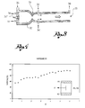
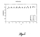
- figure 4 shows the profiles of hardness obtained by applications of tungsten carbide on aluminium substrates having thickness of about one millimetre, by prior art processes.
- the hardness values shown are of the Vickers type and have been measured with a standard load equal to 0.1 kg.
- the hardness values are affected by the layer concerned by the temperature induced by the metallization technique, so the mechanical features decrease along with the fatigue resistance of the application-substrate assembly.
- moving from the surface directly impinged by the metallization flow, and thus subject to higher heating, to the inner wall portion it may be noted how micro-hardness increases.
- this result is stronger when the thickness of the wall to be metallized is greater, since an increasingly larger portion of wall is subject to an excessive heating, with subsequent decay of the mechanical features up to the wall core.
- ⁇ FAF it is meant the limit of alternating bending fatigue, that is, the strain below which the fatigue breakage for an alternating bending stress does not occur.
- the application thickness was of about 0.1 millimetres.
- the fatigue test results, with the same load applied, are as follows: Specimen not coated Specimen coated n. of break cycles 20,000-25,000 n. of break cycles 625,000-640,000
- the coatings made on light alloys according to the present invention considerably increase (up to more than 20 times) the number of loading cycles that lead to fatigue breakage.
Landscapes
- Chemical & Material Sciences (AREA)
- Engineering & Computer Science (AREA)
- Physics & Mathematics (AREA)
- Plasma & Fusion (AREA)
- Chemical Kinetics & Catalysis (AREA)
- Materials Engineering (AREA)
- Mechanical Engineering (AREA)
- Metallurgy (AREA)
- Organic Chemistry (AREA)
- Other Surface Treatments For Metallic Materials (AREA)
Applications Claiming Priority (1)
| Application Number | Priority Date | Filing Date | Title |
|---|---|---|---|
| IT000201A ITBS20060201A1 (it) | 2006-11-22 | 2006-11-22 | Apparato per la metallizzazione di componenti metallici e relativo metodo di metallizzazione |
Publications (3)
| Publication Number | Publication Date |
|---|---|
| EP1925688A2 true EP1925688A2 (fr) | 2008-05-28 |
| EP1925688A3 EP1925688A3 (fr) | 2011-03-09 |
| EP1925688B1 EP1925688B1 (fr) | 2017-03-01 |
Family
ID=38886037
Family Applications (1)
| Application Number | Title | Priority Date | Filing Date |
|---|---|---|---|
| EP07119585.3A Active EP1925688B1 (fr) | 2006-11-22 | 2007-10-30 | Méthode de métallisation |
Country Status (2)
| Country | Link |
|---|---|
| EP (1) | EP1925688B1 (fr) |
| IT (1) | ITBS20060201A1 (fr) |
Family Cites Families (6)
| Publication number | Priority date | Publication date | Assignee | Title |
|---|---|---|---|---|
| FR2224991A5 (fr) * | 1973-04-05 | 1974-10-31 | France Etat | |
| EP0360482B1 (fr) * | 1988-09-14 | 1993-08-04 | Hitachi Chemical Co., Ltd. | Procédé pour le revêtement d'une bande métallique avec une matière céramique par projection de plasma |
| JP2681302B2 (ja) * | 1990-02-13 | 1997-11-26 | 株式会社オティックス | 直打式バルブリフタの溶射処理方法及びその装置 |
| US5436426A (en) * | 1993-04-19 | 1995-07-25 | Sulzer Metco (Us), Inc. | Fixture and method for cooling tubular substrate during thermal spraying |
| FR2770156B1 (fr) * | 1997-10-27 | 1999-12-24 | Rosenmund Ag | Procede et dispositif de realisation d'une barre de couchage utilisable dans l'industrie papetiere |
| US6305459B1 (en) * | 1999-08-09 | 2001-10-23 | Ford Global Technologies, Inc. | Method of making spray-formed articles using a polymeric mandrel |
-
2006
- 2006-11-22 IT IT000201A patent/ITBS20060201A1/it unknown
-
2007
- 2007-10-30 EP EP07119585.3A patent/EP1925688B1/fr active Active
Non-Patent Citations (1)
| Title |
|---|
| None |
Also Published As
| Publication number | Publication date |
|---|---|
| EP1925688A3 (fr) | 2011-03-09 |
| EP1925688B1 (fr) | 2017-03-01 |
| ITBS20060201A1 (it) | 2008-05-23 |
Similar Documents
| Publication | Publication Date | Title |
|---|---|---|
| CN100577873C (zh) | 制备含有金属基体复合物的耐磨涂层的方法及由其制备的涂层 | |
| Khan et al. | Effect of residual stresses on air plasma sprayed thermal barrier coatings | |
| US8597724B2 (en) | Corrosion protective coating through cold spray | |
| US7805822B2 (en) | Process for removing thermal barrier coatings | |
| Yang et al. | Evolution of microstructure and mechanical properties of cold spray additive manufactured aluminum deposit on copper substrate | |
| JP2004137602A (ja) | 基材にコーティングを施す方法 | |
| EP1877598B1 (fr) | Reparation et recharge effectuees avec du magnesium | |
| CN101705842B (zh) | 一种燃气轮机旁通可变机构内侧环、外侧环表面耐磨层及其制备方法 | |
| EP1925688B1 (fr) | Méthode de métallisation | |
| CN114196948B (zh) | 航空发动机高温合金上高温防护涂层的加工方法 | |
| US10711636B2 (en) | Feedstocks for use in coating components | |
| CN111004991A (zh) | 一种热作模具钢高耐磨高耐蚀保护层的制备方法 | |
| CN110952060A (zh) | 一种减速器动力传输轴的表面处理方法及涂层 | |
| US8887662B2 (en) | Pressure masking systems and methods for using the same | |
| CN105063539B (zh) | 一种球磨机衬板耐磨涂层的制备方法 | |
| Sakaki | Cold Spray Process~ Overview and Application Trends~ | |
| RU2633434C2 (ru) | Устройство и способ улучшения физических свойств поверхности детали | |
| CN107460431A (zh) | 一种改善6061铝合金表面等离子喷涂Ni60A涂层结合强度的方法 | |
| CN118880225B (zh) | 一种钛合金耐磨抗烧蚀复合强化层及其制备方法 | |
| Dlouhá et al. | Adhesion of selected thermally sprayed coatings on additive manufactured maraging steel | |
| Ghelichi et al. | Experimental study of shot peening followed by cold spray coating on residual stresses of the treated parts | |
| Ito et al. | Damage Evaluation of Thermal Barrier Coatings Subjected to a High-Velocity Impingement of a Solid Sphere under Room and High Temperature Conditions | |
| Leblanc Robert | Influence of Nozzle Material and Spray Parameters on Pure Aluminum and Aluminum 7075 coatings using Cold Gas Dynamic Spray | |
| HK1094175B (en) | Process for removing thermal barrier coatings | |
| HK1094175A (en) | Process for removing thermal barrier coatings |
Legal Events
| Date | Code | Title | Description |
|---|---|---|---|
| PUAI | Public reference made under article 153(3) epc to a published international application that has entered the european phase |
Free format text: ORIGINAL CODE: 0009012 |
|
| AK | Designated contracting states |
Kind code of ref document: A2 Designated state(s): AT BE BG CH CY CZ DE DK EE ES FI FR GB GR HU IE IS IT LI LT LU LV MC MT NL PL PT RO SE SI SK TR |
|
| AX | Request for extension of the european patent |
Extension state: AL BA HR MK RS |
|
| PUAL | Search report despatched |
Free format text: ORIGINAL CODE: 0009013 |
|
| AK | Designated contracting states |
Kind code of ref document: A3 Designated state(s): AT BE BG CH CY CZ DE DK EE ES FI FR GB GR HU IE IS IT LI LT LU LV MC MT NL PL PT RO SE SI SK TR |
|
| AX | Request for extension of the european patent |
Extension state: AL BA HR MK RS |
|
| RIC1 | Information provided on ipc code assigned before grant |
Ipc: C23C 4/14 20060101ALI20110202BHEP Ipc: B05B 7/20 20060101ALI20110202BHEP Ipc: C23C 4/12 20060101AFI20080408BHEP |
|
| 17P | Request for examination filed |
Effective date: 20110908 |
|
| AKX | Designation fees paid |
Designated state(s): AT BE BG CH CY CZ DE DK EE ES FI FR GB GR HU IE IS IT LI LT LU LV MC MT NL PL PT RO SE SI SK TR |
|
| 17Q | First examination report despatched |
Effective date: 20111102 |
|
| GRAJ | Information related to disapproval of communication of intention to grant by the applicant or resumption of examination proceedings by the epo deleted |
Free format text: ORIGINAL CODE: EPIDOSDIGR1 |
|
| RIC1 | Information provided on ipc code assigned before grant |
Ipc: B05B 7/20 20060101ALI20160920BHEP Ipc: C23C 4/129 20160101ALI20160920BHEP Ipc: C23C 4/14 20160101ALI20160920BHEP Ipc: C23C 4/12 20060101AFI20160920BHEP Ipc: B05B 7/16 20060101ALI20160920BHEP |
|
| GRAP | Despatch of communication of intention to grant a patent |
Free format text: ORIGINAL CODE: EPIDOSNIGR1 |
|
| INTG | Intention to grant announced |
Effective date: 20161102 |
|
| GRAS | Grant fee paid |
Free format text: ORIGINAL CODE: EPIDOSNIGR3 |
|
| GRAA | (expected) grant |
Free format text: ORIGINAL CODE: 0009210 |
|
| AK | Designated contracting states |
Kind code of ref document: B1 Designated state(s): AT BE BG CH CY CZ DE DK EE ES FI FR GB GR HU IE IS IT LI LT LU LV MC MT NL PL PT RO SE SI SK TR |
|
| REG | Reference to a national code |
Ref country code: GB Ref legal event code: FG4D |
|
| REG | Reference to a national code |
Ref country code: CH Ref legal event code: EP Ref country code: AT Ref legal event code: REF Ref document number: 871441 Country of ref document: AT Kind code of ref document: T Effective date: 20170315 |
|
| REG | Reference to a national code |
Ref country code: IE Ref legal event code: FG4D |
|
| REG | Reference to a national code |
Ref country code: DE Ref legal event code: R096 Ref document number: 602007049936 Country of ref document: DE |
|
| REG | Reference to a national code |
Ref country code: DE Ref legal event code: R082 Ref document number: 602007049936 Country of ref document: DE Representative=s name: MUELLER-BORE & PARTNER PATENTANWAELTE PARTG MB, DE Ref country code: DE Ref legal event code: R081 Ref document number: 602007049936 Country of ref document: DE Owner name: MARCONI, GIAN PAOLO, IT Free format text: FORMER OWNER: MARCONI, GIAN PAOLO, PUEGNAGO DEL GARDA, IT |
|
| RAP2 | Party data changed (patent owner data changed or rights of a patent transferred) |
Owner name: MARCONI, GIAN PAOLO |
|
| REG | Reference to a national code |
Ref country code: NL Ref legal event code: MP Effective date: 20170301 |
|
| RIN2 | Information on inventor provided after grant (corrected) |
Inventor name: MARCONI, GIAN PAOLO |
|
| REG | Reference to a national code |
Ref country code: LT Ref legal event code: MG4D |
|
| REG | Reference to a national code |
Ref country code: AT Ref legal event code: MK05 Ref document number: 871441 Country of ref document: AT Kind code of ref document: T Effective date: 20170301 |
|
| PG25 | Lapsed in a contracting state [announced via postgrant information from national office to epo] |
Ref country code: GR Free format text: LAPSE BECAUSE OF FAILURE TO SUBMIT A TRANSLATION OF THE DESCRIPTION OR TO PAY THE FEE WITHIN THE PRESCRIBED TIME-LIMIT Effective date: 20170602 Ref country code: FI Free format text: LAPSE BECAUSE OF FAILURE TO SUBMIT A TRANSLATION OF THE DESCRIPTION OR TO PAY THE FEE WITHIN THE PRESCRIBED TIME-LIMIT Effective date: 20170301 Ref country code: LT Free format text: LAPSE BECAUSE OF FAILURE TO SUBMIT A TRANSLATION OF THE DESCRIPTION OR TO PAY THE FEE WITHIN THE PRESCRIBED TIME-LIMIT Effective date: 20170301 |
|
| PG25 | Lapsed in a contracting state [announced via postgrant information from national office to epo] |
Ref country code: BG Free format text: LAPSE BECAUSE OF FAILURE TO SUBMIT A TRANSLATION OF THE DESCRIPTION OR TO PAY THE FEE WITHIN THE PRESCRIBED TIME-LIMIT Effective date: 20170601 Ref country code: ES Free format text: LAPSE BECAUSE OF FAILURE TO SUBMIT A TRANSLATION OF THE DESCRIPTION OR TO PAY THE FEE WITHIN THE PRESCRIBED TIME-LIMIT Effective date: 20170301 Ref country code: AT Free format text: LAPSE BECAUSE OF FAILURE TO SUBMIT A TRANSLATION OF THE DESCRIPTION OR TO PAY THE FEE WITHIN THE PRESCRIBED TIME-LIMIT Effective date: 20170301 Ref country code: SE Free format text: LAPSE BECAUSE OF FAILURE TO SUBMIT A TRANSLATION OF THE DESCRIPTION OR TO PAY THE FEE WITHIN THE PRESCRIBED TIME-LIMIT Effective date: 20170301 Ref country code: LV Free format text: LAPSE BECAUSE OF FAILURE TO SUBMIT A TRANSLATION OF THE DESCRIPTION OR TO PAY THE FEE WITHIN THE PRESCRIBED TIME-LIMIT Effective date: 20170301 |
|
| PG25 | Lapsed in a contracting state [announced via postgrant information from national office to epo] |
Ref country code: NL Free format text: LAPSE BECAUSE OF FAILURE TO SUBMIT A TRANSLATION OF THE DESCRIPTION OR TO PAY THE FEE WITHIN THE PRESCRIBED TIME-LIMIT Effective date: 20170301 |
|
| PG25 | Lapsed in a contracting state [announced via postgrant information from national office to epo] |
Ref country code: CZ Free format text: LAPSE BECAUSE OF FAILURE TO SUBMIT A TRANSLATION OF THE DESCRIPTION OR TO PAY THE FEE WITHIN THE PRESCRIBED TIME-LIMIT Effective date: 20170301 Ref country code: EE Free format text: LAPSE BECAUSE OF FAILURE TO SUBMIT A TRANSLATION OF THE DESCRIPTION OR TO PAY THE FEE WITHIN THE PRESCRIBED TIME-LIMIT Effective date: 20170301 Ref country code: SK Free format text: LAPSE BECAUSE OF FAILURE TO SUBMIT A TRANSLATION OF THE DESCRIPTION OR TO PAY THE FEE WITHIN THE PRESCRIBED TIME-LIMIT Effective date: 20170301 Ref country code: RO Free format text: LAPSE BECAUSE OF FAILURE TO SUBMIT A TRANSLATION OF THE DESCRIPTION OR TO PAY THE FEE WITHIN THE PRESCRIBED TIME-LIMIT Effective date: 20170301 |
|
| REG | Reference to a national code |
Ref country code: FR Ref legal event code: PLFP Year of fee payment: 11 |
|
| PG25 | Lapsed in a contracting state [announced via postgrant information from national office to epo] |
Ref country code: PL Free format text: LAPSE BECAUSE OF FAILURE TO SUBMIT A TRANSLATION OF THE DESCRIPTION OR TO PAY THE FEE WITHIN THE PRESCRIBED TIME-LIMIT Effective date: 20170301 Ref country code: IS Free format text: LAPSE BECAUSE OF FAILURE TO SUBMIT A TRANSLATION OF THE DESCRIPTION OR TO PAY THE FEE WITHIN THE PRESCRIBED TIME-LIMIT Effective date: 20170701 Ref country code: PT Free format text: LAPSE BECAUSE OF FAILURE TO SUBMIT A TRANSLATION OF THE DESCRIPTION OR TO PAY THE FEE WITHIN THE PRESCRIBED TIME-LIMIT Effective date: 20170703 |
|
| REG | Reference to a national code |
Ref country code: DE Ref legal event code: R097 Ref document number: 602007049936 Country of ref document: DE |
|
| PLBE | No opposition filed within time limit |
Free format text: ORIGINAL CODE: 0009261 |
|
| STAA | Information on the status of an ep patent application or granted ep patent |
Free format text: STATUS: NO OPPOSITION FILED WITHIN TIME LIMIT |
|
| PG25 | Lapsed in a contracting state [announced via postgrant information from national office to epo] |
Ref country code: DK Free format text: LAPSE BECAUSE OF FAILURE TO SUBMIT A TRANSLATION OF THE DESCRIPTION OR TO PAY THE FEE WITHIN THE PRESCRIBED TIME-LIMIT Effective date: 20170301 |
|
| 26N | No opposition filed |
Effective date: 20171204 |
|
| PG25 | Lapsed in a contracting state [announced via postgrant information from national office to epo] |
Ref country code: SI Free format text: LAPSE BECAUSE OF FAILURE TO SUBMIT A TRANSLATION OF THE DESCRIPTION OR TO PAY THE FEE WITHIN THE PRESCRIBED TIME-LIMIT Effective date: 20170301 |
|
| PG25 | Lapsed in a contracting state [announced via postgrant information from national office to epo] |
Ref country code: MC Free format text: LAPSE BECAUSE OF FAILURE TO SUBMIT A TRANSLATION OF THE DESCRIPTION OR TO PAY THE FEE WITHIN THE PRESCRIBED TIME-LIMIT Effective date: 20170301 |
|
| REG | Reference to a national code |
Ref country code: CH Ref legal event code: PL |
|
| REG | Reference to a national code |
Ref country code: IE Ref legal event code: MM4A |
|
| PG25 | Lapsed in a contracting state [announced via postgrant information from national office to epo] |
Ref country code: LI Free format text: LAPSE BECAUSE OF NON-PAYMENT OF DUE FEES Effective date: 20171031 Ref country code: CH Free format text: LAPSE BECAUSE OF NON-PAYMENT OF DUE FEES Effective date: 20171031 Ref country code: LU Free format text: LAPSE BECAUSE OF NON-PAYMENT OF DUE FEES Effective date: 20171030 |
|
| REG | Reference to a national code |
Ref country code: BE Ref legal event code: MM Effective date: 20171031 |
|
| PG25 | Lapsed in a contracting state [announced via postgrant information from national office to epo] |
Ref country code: BE Free format text: LAPSE BECAUSE OF NON-PAYMENT OF DUE FEES Effective date: 20171031 |
|
| PG25 | Lapsed in a contracting state [announced via postgrant information from national office to epo] |
Ref country code: MT Free format text: LAPSE BECAUSE OF NON-PAYMENT OF DUE FEES Effective date: 20171030 |
|
| PG25 | Lapsed in a contracting state [announced via postgrant information from national office to epo] |
Ref country code: IE Free format text: LAPSE BECAUSE OF NON-PAYMENT OF DUE FEES Effective date: 20171030 |
|
| REG | Reference to a national code |
Ref country code: FR Ref legal event code: PLFP Year of fee payment: 12 |
|
| PG25 | Lapsed in a contracting state [announced via postgrant information from national office to epo] |
Ref country code: HU Free format text: LAPSE BECAUSE OF FAILURE TO SUBMIT A TRANSLATION OF THE DESCRIPTION OR TO PAY THE FEE WITHIN THE PRESCRIBED TIME-LIMIT; INVALID AB INITIO Effective date: 20071030 |
|
| PG25 | Lapsed in a contracting state [announced via postgrant information from national office to epo] |
Ref country code: CY Free format text: LAPSE BECAUSE OF NON-PAYMENT OF DUE FEES Effective date: 20170301 |
|
| PG25 | Lapsed in a contracting state [announced via postgrant information from national office to epo] |
Ref country code: TR Free format text: LAPSE BECAUSE OF FAILURE TO SUBMIT A TRANSLATION OF THE DESCRIPTION OR TO PAY THE FEE WITHIN THE PRESCRIBED TIME-LIMIT Effective date: 20170301 |
|
| PGFP | Annual fee paid to national office [announced via postgrant information from national office to epo] |
Ref country code: IT Payment date: 20250827 Year of fee payment: 19 |
|
| PGFP | Annual fee paid to national office [announced via postgrant information from national office to epo] |
Ref country code: FR Payment date: 20250930 Year of fee payment: 19 |
|
| PGFP | Annual fee paid to national office [announced via postgrant information from national office to epo] |
Ref country code: DE Payment date: 20251027 Year of fee payment: 19 |
|
| PGFP | Annual fee paid to national office [announced via postgrant information from national office to epo] |
Ref country code: GB Payment date: 20251022 Year of fee payment: 19 |